Optimizing UI Layouts for Deformable Face-Rig Manipulation
←
→
Page content transcription
If your browser does not render page correctly, please read the page content below
Optimizing UI Layouts for Deformable Face-Rig Manipulation
JOONHO KIM, University of Toronto, Canada
KARAN SINGH, University of Toronto, Canada

Fig. 1. Expressive deformable models like faces have many independently controlled rig parameters (a). Animators increasingly hand-craft in-situ
UI layouts for such face-rigs (b). We distill their design choices into a set of layout principles (c). We then present an algorithm to produce optimal
in-situ UI layouts that match animator expectation (d); enabling a direct on-shape deformation interface (e), where rig parameters can be both
independently manipulated (cursor on white control, top to middle), and best-fit computed (blue controls) to match the direct manipulation of the
shape (cursor on face, bottom) [Lewis and Anjyo 2010]. Our in-situ UI layouts can be further customized and refined by animators (f).

Complex deformable face-rigs have many independent parameters that control ACM Reference Format:
the shape of the object. A human face has upwards of 50 parameters (FACS Joonho Kim and Karan Singh. 2021. Optimizing UI Layouts for Deformable
Action Units), making conventional UI controls hard to find and operate. Face-Rig Manipulation. ACM Trans. Graph. 40, 4, Article 172 (August 2021),
Animators address this problem by tediously hand-crafting in-situ layouts of 12 pages. https://doi.org/10.1145/3450626.3459842
UI controls that serve as visual deformation proxies, and facilitate rapid shape
exploration. We propose the automatic creation of such in-situ UI control
layouts. We distill the design choices made by animators into mathematical 1 INTRODUCTION
objectives that we optimize as the solution to an integer quadratic program-
 Character rigging is an art that provides a number of meaningful
ming problem. Our evaluation is three-fold: we show the impact of our design
principles on the resulting layouts; we show automated UI layouts for com-
 interactive controls (like strings of a puppet) with which to bring a
plex and diverse face rigs, comparable to animator hand-crafted layouts; and character to life [Allen and Murdock 2008]. The creative flow and
we conduct a user study showing our UI layout to be an effective approach to expressivity of a puppet-master (animator) is impacted not only by
face-rig manipulation, preferable to a baseline slider interface. how the strings manipulate a puppet (control parameters), but by
 the relationship between the strings and the puppet-master (control
CCS Concepts: • Computing methodologies → Animation; UI.
 UI and its layout). While much CG research has focused on the
Additional Key Words and Phrases: facial animation, deformable rigs, UI. anatomic, geometric, and dynamic aspects of character rigging, re-
 search into the layout and interactive control of rig parameters is
Authors’ addresses: Joonho Kim, University of Toronto, Toronto, Canada, joonho@dgp. relatively less explored. This paper thus, introduces the problem of
toronto.edu; Karan Singh, University of Toronto, Toronto, Canada, karan@dgp.toronto. creating animator-optimal, in-situ, layouts of UI controls to facilitate
edu.
 the manipulation of a deformable character rig (Figure 1).
Permission to make digital or hard copies of all or part of this work for personal or
 Motivation
classroom use is granted without fee provided that copies are not made or distributed Professional character animation rigs have hundreds of interactive
for profit or commercial advantage and that copies bear this notice and the full citation controls. A Facial Action Coding System (FACS)-based face-rig [Ek-
on the first page. Copyrights for components of this work owned by others than ACM
must be honored. Abstracting with credit is permitted. To copy otherwise, or republish, man 1997] for example has upwards of 50 independently controlled
to post on servers or to redistribute to lists, requires prior specific permission and/or a Action Units (AUs) that define a facial expression. Modern face rigs
fee. Request permissions from permissions@acm.org. often go well beyond FACS to model sub-muscular behavior, sim-
© 2021 Association for Computing Machinery.
0730-0301/2021/8-ART172 $15.00 ulate aging, or represent families of faces [Seymour 2016, 2018],
https://doi.org/10.1145/3450626.3459842 resulting in rigs with hundreds of parameters [Seymour 2019].

 ACM Trans. Graph., Vol. 40, No. 4, Article 172. Publication date: August 2021.
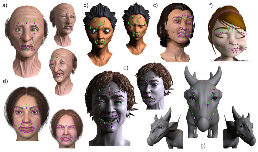
172:2 • Tagliasacchi et al.

 These rigs are animated by traditional keyframing [Navone 2020], capture; provide in-situ UI layouts for novices, and one-off or non-
performance capture [Seymour 2019; Tewari et al. 2017], or even standard characters with stylized proportions (animal in Figure 18);
speech audio [Edwards et al. 2020]. While rigs are increasingly and generalize to arbitrary parametric deformations (Figures 16).
driven by performance capture, the role of an animator remains Problem Statement and Overview
as important as ever: the popular genre of stylized animation is We observe that the feel of direct manipulation can be provided by
still tediously keyframed [Navone 2020], and performance captured mapping UI handles to the deformation of a representative vertex of
animation is still cleaned-up and embellished by animators working the shape. Defining an in-situ layout can thus be cast as a mapping
with interactive deformable rigs [Seymour 2018]. Film rigs are also : −→ , where is a set of rig parameters/controls, and a set
ephemeral, with base rigs continually evolving to account for context of 3D shape vertices. We then formulate the various aesthetic and
specific corrections and shot customization [Li et al. 2013]. usability properties that hand-crafted layouts imbibe (Figure 1(c))
 The default UI for such rigs in commercial animation software like as an extendable set of energy terms, defined for any given layout
Maya is a disparate and long scrollable list of deformation parameter . The optimal in-situ layout is thus found by computing the energy
sliders, only a fraction of which might be concurrently viewable minimizing control to vertex mapping (Figure 1). While our approach
(Figure 1(a)). Interacting with these sliders is woefully inadequate: is focused on face-rigs (Figure 17, 18), our technique is designed to
knowing which AUs are needed to effect a desired change to the face be generally applicable to parametric deformations (Figure 16).
is not obvious. These AUs must then be found by name in the slider A review of related work (Section 2), is followed by a discussion
list and manipulated while shifting visual focus between the 2D UI of our overall problem space, and development of an extendable set
and the 3D face. of in-situ UI layout design principles (Section 3). Section 4 presents
 Manipulating such a large number of control parameters is chal- the details of our optimization algorithm. Section 5 presents a user
lenging. Direct manipulation techniques such as [Lewis and Anjyo study comparing our UI layout to a baseline slider interface, and
2010] inverse-fit a configuration of rig parameter values, whose artist hand-crafted rig UI layout. Further evaluation, limitations and
deformed shape best-matches a user manipulated target shape. Low- directions for future work are presented in Section 6, 7.
dimensional data-driven manifolds allow users to rapidly explore a
meaningful subspace of the high-dimensional rig parameter space
[Abdrashitov et al. 2020]. While animators appreciate the simplicity
and efficiency of such approaches, they also demand independent
control of rig parameters for the fine control needed to showcase their
skills (similar to the complementary use of both Forward and Inverse
Kinematics in skeletal animation) [Osipa 2010] (Figure 1(e)). As a
result most riggers and animators meticulously hand-craft in-situ UI
layouts to drive their character rigs (Figure 1(b)). Such in-situ/on-
screen interfaces (Figure 2) are also increasingly prevalent in game
engines, and mixed reality platforms: to support expressive charac-
ter posing and animation for film, games, social media and avatar
customization.
 Each UI control in Figure 1(b) was hand-crafted in a 2D frontal
view, designed to largely emulate the view-projected deformation
trajectory1 of a representative shape vertex, across extreme values of Fig. 2. Our rig UI layout alongside hand-crafted UI layout for the 24K
a corresponding rig parameter. The UI layout took the rigger about a vertex Metahuman with 142 parameters ©Epic Games, Inc.
day to create, intuitively picking a visually meaningful trajectory for
each parameter, and laying it out respectful of symmetry, occlusion,
 2 RELATED WORK
and maximizing the use of space around the shape. Creating such a The problem of rigging and motion control for interactive character
layout by hand gets significantly harder with 3D curve trajectories animation is at least three decades old [Badler et al. 1990]. We focus
(Figure 16) and evolving rig parameters (Figure 12). Hand-crafted on character rigging: the interactive set-up that allows animators
rig layouts are also brittle to layout re-targeting across characters to manipulate parameters that control the deformation of character
with diverse proportions, topology, and rig parameters. geometry. The majority of rigging research concerns algorithms
 Our primary contribution is thus: an analysis of the artistic insights that actually deform a 3D model, based on configurations of rig
in creating hand-crafted face-rig UI layouts and, subsequently, an parameters. Work relevant to this paper instead addresses the user
optimization algorithm that fully automates the creation of such interface between rig parameters and the animator, broadly classified
UI layouts. Our resulting UI layouts have many applications: they under: deformation proxies and widgets, high-dimensional UIs, and
validate manual layout design choices and can optimally complete direct manipulation of deformable shape.
a partially hand-crafted rig; provide an in-situ UI layout for one- Deformation Proxies and Widgets
off shot-specific/layered/corrective shapes common in performance UI widgets are visual 3D elements designed to provide an in-situ
 interactive interface to manipulating objects and aspects of a virtual
1 The blendShape weight parameters in Figure 1 produce linear trajectories, but in general scene [Bier 1987]. Widgets are typically hand-designed to capture
this trajectory is a parametric 3D curve. the form/function of parameters they control, like a rotation arc-ball.

ACM Trans. Graph., Vol. 40, No. 4, Article 172. Publication date: August 2021.
Optimizing UI Layouts for Deformable Face-Rig Manipulation • 172:3

 A variety of general frameworks for 3D widget UI element controls specific parameters (top, middle), and selecting
design have been developed [Stevens et al. 1994], the shape elsewhere sets parameters best-fit to direct manipulation.
including approaches to interactively combine sim-
ple widgets into composite widgets for complex 3D object manipula- 3 DESIGN PRINCIPLES
tion [Schmidt et al. 2008]. We automatically create such a composite Direct, in-situ interfaces keep users immersed and focused on their
widget for deformable shapes. Deformable objects are often inter- creative task in a 3D scene. Our general problem space is vast, with
actively manipulated using proxy objects like lattices [Sederberg many design dimensions, including:
and Parry 1986] or wires [Singh and Fiume 1998], whose direct Rig parameter structure and mapping: clusters and hierarchies
manipulation is intrinsically responsible for the resulting shape de- of rig parameters, and their mapping to UI elements can provide a
formation. Our approach can augment such deformable proxies by trade-off between visual clutter and coarse-to-fine parameter inter-
automating the UI layout of various deformation parameters. While action. Additionally, parameter structuring can greatly reduce the
our optimization objectives are visual design and interaction based computational complexity of layout optimization.
[Agrawala et al. 2011], we also draw inspiration from research on UI element form: the geometric shape of a UI element/widget is
computing optimal marker configurations to accurately capture facial both: an interaction handle for its rig parameter(s), and a visual proxy
deformations [Le et al. 2013]. for the resulting deformation (for eg. the straight sliders convey a
High-Dimensional User Interfaces linear blendShape trajectory, and the eyelash/chin curves convey the
Exploring high-dimensional design spaces in a creative context is a deformation due to squint/jawOpen parameters in Figure 1(b)).
challenging task. Data-driven techniques, often aimed at novice users, UI element function: the interaction workflow with UI elements can
reduce the dimensionality of the parameter space [Kry et al. 2002], address design issues ranging from UI clutter, to providing visual
employ design galleries of good representative examples [Brochu feedback and control over deformation properties and constraints.
et al. 2010; Gibson et al. 1997], or use crowd-sourced visualizations UI element layout: a successful layout, for a given mapping of rig
usually to aid novice users [Koyama et al. 2014; Talton et al. 2009]. parameters to UI elements, should be optimized for visual meaning,
Recently data-driven manifolds of deformable shape [Bailey et al. aesthetic, and ease of interaction.
2020] have also been used in the context of rapidly posing expressive While we use parameter clustering to aid layout optimization and
faces [Abdrashitov et al. 2020]. Expert animators are not intimi- show three different rig parameter to UI element mappings, this paper
dated by a large number of parameters, as long as their interface remains largely focused on UI layout, leaving detailed explorations
is streamlined for efficient interaction that maintains their creative of other design aspects to future work.
flow. Hand-crafted in-situ rig UI layouts (Figure 3) exemplify such
an interface. This paper is the first to automatically create such rig
UI.
Direct Manipulation of Deformable Shapes
Sketch-based and direct manipulation alternatives can streamline
spatially goal-directed animation [Gleicher 1992] and reduce the
tedium of sequentially manipulating individual parameters of a high-
dimensional rig. Inverse Kinematics techniques (IK) for constrained
goals, like walking or grasping [Parent 2012], or aesthetic line-of-
action sketching [Guay et al. 2013] position multiple joint parameters
of a deformable character using high-level animator input. Facial
domain systems like Face-Poser [Lau et al. 2009] use screen-space
input as 2D point, stroke, and curve constraints with a deformation
prior learned from a prerecorded facial expression database. Other
approaches [Miranda et al. 2011; Sucontphunt et al. 2008] use 2D
drawing and curve-editing to drive 3D marker-based facial expres- Fig. 3. Hand-crafted rig UI layouts: the control UI is a mix of manipula-
sions. Performance capture of the face or body [Williams 1990] is tion handle shapes, line/curve sliders, and patches in 3D (a) or 2D (b).
a popular approach to driving a 3D deformable shape from mark- The layouts are symmetric, well spread in space, minimally occluded
 and correspond directly to the shape deformation. The layouts can
ers or video of an actor. Much of this work is not animator-centric,
 be placed on (a) or off the face (b) and UI elements for global rig
but techniques such as Weise et al. [2011]; Zell et al. [2017] can fit parameters like gender, are typically placed beside the rig UI (b). Ray
performance capture to the parameters of a deformable rig. In this Character Rig by CGTarian ©UAB MOCAP.LT.
spirit direct manipulation methods [Cetinaslan and Orvalho 2018;
Lewis and Anjyo 2010] compute rig parameters from the manipula- We distill an understanding of animator intuition in rig UI creation
tion of vertices on a 3D face, with varying degrees of local spatial from conversations with animators and an analysis of hand-crafted
control [Tena et al. 2011]. Direct manipulation techniques perfectly rigs (Figure 3 and near a dozen proprietary professional rigs). In all in-
complement our work, for the same reason that both inverse and situ rigs the manipulation handle of a parameter was aligned to at least
forward kinematics are necessary for animation. Figure 1(e) and ac- approximately track the deformation of a point on the face resulting
companying video shows our combined interface, where selecting a from manipulating that parameter. In many instances 2D handles
 matched the deformation projected in a front view (Figure 7, 17).

 ACM Trans. Graph., Vol. 40, No. 4, Article 172. Publication date: August 2021.
172:4 • Tagliasacchi et al.
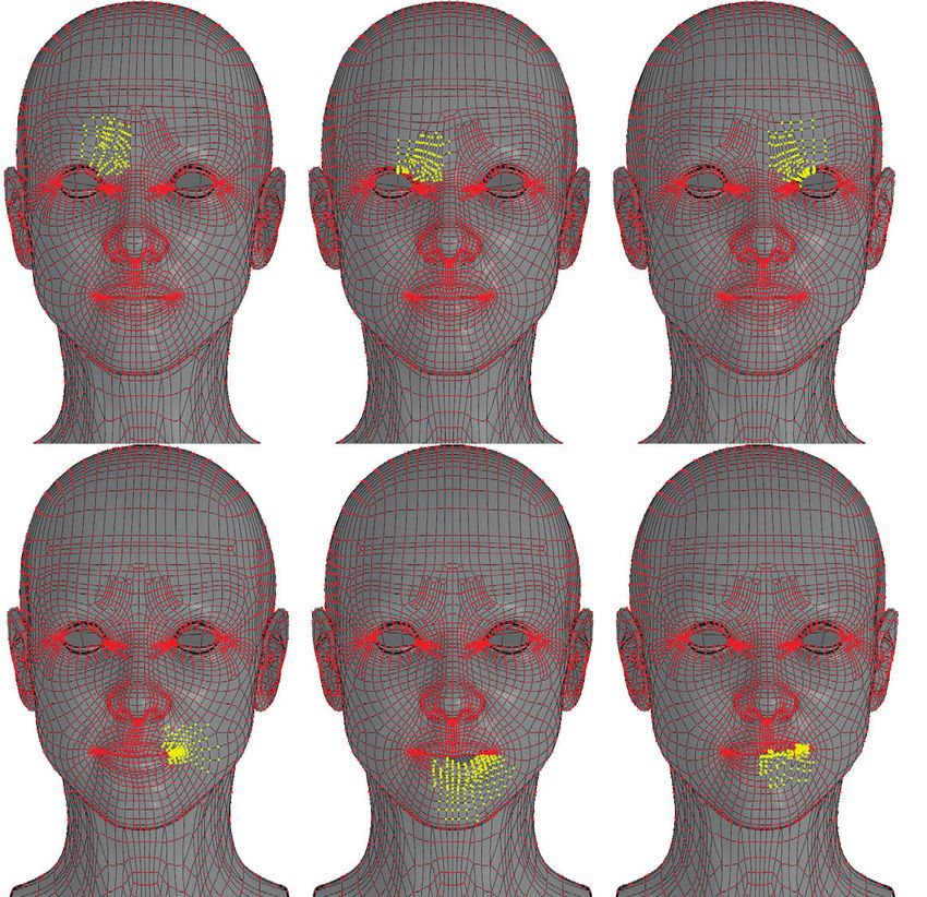
The rig parameters that define multi-parameter elements typically
deform the same region somewhat orthogonally, such as a jaw-open-
close and jaw-left-right. While multiple rig parameters are used to
define patch and fan UI elements, such elements should be repre-
sented by a single representative control in the layout , so that the
element can be created at a common vertex in the optimal layout .
Below we thus assume each control to map to a unique UI element
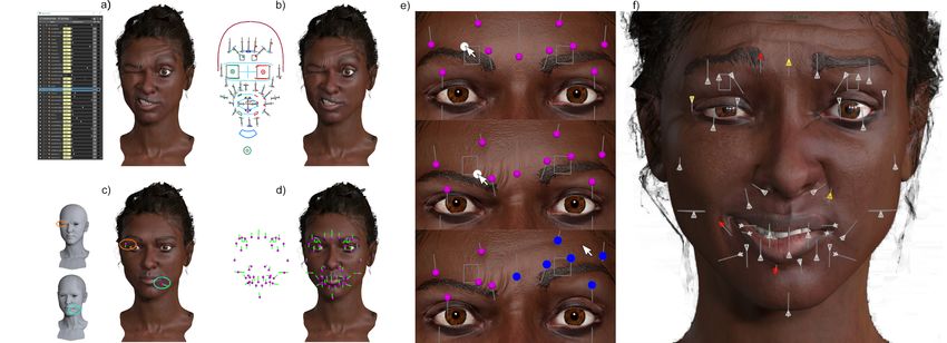
Fig. 4. UI elements on the eyebrows (left) can remain static (middle) or .
interactively adapt (right) to parameter manipulation (white controls).
3.1 Feeling of Direct Manipulation
We thus formalize the UI layout problem as a mapping : −→
, where is a set of rig parameters 1 .. and the set of
3D model vertices 1 .. . Let = { 1 .. } be a configuration
of the rig parameter values, where lies between and
values for control parameter . Let ∈ {1.. } be the vertex index
that is mapped to under some layout = { 1 .. }, and ( ) Fig. 5. Rig UI layouts can be optimized for arbitrary UI elements, such
as the sliders, patches and fans shown. Further, our algorithm can
the parametric 3D trajectory of vertex , as it deforms under some
automatically group rig parameters with large overlapping regions of
parameter configuration (for eg. the default parameter values) with
deformation, to define 2-parameter patches, and multi-parameter fans.
only changing from = to = . For the blendShape
weight parameters seen in Figure 1, this trajectory is a straight 3.3 UI Layout Design Objectives
line (in general ( ) is a parametric 3D curve).
We observe that the following extendable set of objectives guide
Direct manipulation dictates that the UI element for any control
the functional and aesthetic quality of a UI layout. We discuss these
should be shaped by . The UI elements in Figure 1,2,17 are
objectives for single-parameter sliders. For a multi-parameter UI
mostly 3D line sliders, but can also conform in shape to the region
element (patch or fan), we set the objective to be the worst objective
being deformed (for eg. eyelash/lip/chin in Figure 1(b)). We thus need
value computed for each of its mapped parameters independently.
to support general element shapes and trajectories, like parametric
Maximal Displacement
curves, patches, and fans (Figure 5), and our goal is to find a layout
The visual impact of manipulating a rig parameter is best observed
, whose UI element shape and trajectory optimize certain functional
in regions where it invokes large deformations. Functionally, larger
and aesthetic criteria.
deformation trajectories also produce larger UI elements that are eas-
Note that the trajectory = { 1, .. } for any layout , also de-
ier to manipulate with better resolution. A user wishing to squint an
pends on the parameter values . Conceptually we can either find
eye in Figure 1 for eg., would expect to tug directly on a UI element
an optimal layout for some default parameter configuration, or con-
that tracks a vertex on the eyelid, instead of a visually confusing and
stantly recompute an optimal layout as parameter values change.
unusable zero-length UI element attached to say, a vertex on the chin.
Animator consultations and HCI principles [Gajos et al. 2006] con-
As a down-side, a large UI element may disproportionately occupy
firm that persistent layouts become familiar and more predictable
space and interfere with the 3D shape and UI elements of other rig
for users. Optimal layouts, like hand-crafted layouts, are thus only
parameters. We thus model this objective for a candidate layout as
computed once, for some neutral/default or user-defined parame-
a function of the arc-length of its deformation trajectories .
ter configuration . While the layout mapping remains fixed, all UI
Minimal Inter-Element Overlap
elements should deform to remain attached to the interactively manip-
The UI elements in hand-crafted layouts (Figure 3) are spatially well-
ulated shape (Figure 4), to provide a feeling of direct manipulation.
spread. Elements that intersect or have significant spatial overlap
are unattractive, visually cluttered and difficult to select unambigu-
3.2 UI Elements ously. We thus aim to minimize inter-element overlap (or alternately
Figure 5 shows various linear UI ele- maximize inter-element distance).
ments. A single-parameter slider inde- Figure 6 shows the trade-off between the use of maximal displace-
pendently manipulates a rig parameter. A ment, and minimal inter-element overlap in our approach.
two-parameter patch allows simultane- Element-Model Occlusion
ous 2-DOF manipulation of two param- It is visually desirable for UI elements to remain largely un-occluded
eters. A multi-parameter fan (inset), extends a patch to allow si- by the 3D shape during interaction (even though they can always be
multaneous 2-DOF manipulation of adjacent fan parameters. The drawn un-occluded as an overlay). Locally, we thus favour trajec-
trajectory tangents (green) for the parameters at the common layout tories for control whose tangent ′ at the default configuration,
vertex are projected (blue) onto the tangent plane at the vertex, and aligns well with the 3D vertex normal for the layout vertex . This
the radial angular order of the projected tangents in this plane, defines alignment can be measured as a function of the dot product of the
the adjacency of parallelogram patches (angle ≤ 180 ) of the fan. vectors. We can also address element-model occlusion in a view
ACM Trans. Graph., Vol. 40, No. 4, Article 172. Publication date: August 2021.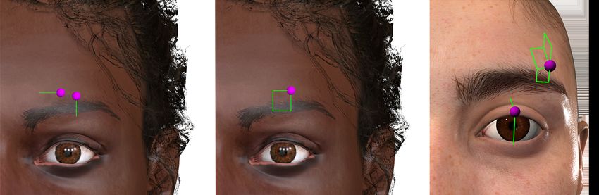
Optimizing UI Layouts for Deformable Face-Rig Manipulation • 172:5
dependent fashion by limiting candidate layout vertices, to those that
are visible from a given view in the default configuration. Finally if
a view-dependent 2D layout is desired, the optimal layout can fur-
ther be computed after view-projecting elements in 2D, to penalize
strongly foreshortened UI elements (Figure 7).
Symmetric Elements
As characters are inherently symmetric, most rigs have parameter sets
that deform shape symmetrically (for eg. a left-squint and right-squint
control). Such symmetric controls are readily inferred automatically
[Mitra et al. 2012], or can be user annotated. UI elements for symmet-
ric parameters should convey that symmetry visually. Given controls
, subject to some symmetry transform , we enforce precise sym-
metry by removing from the layout optimization, but retaining its
UI element as part of (i.e. the UI element for is defined as both
and its symmetric element ( )). This ensures that the optimal
will account for both UI elements it is responsible for creating, and
that the UI elements for and are symmetric. The above trivially
generalizes to multi-fold symmetry by optimizing the UI layout of
one representative control for each set of symmetric controls.
Symmetric Deformations
Characters often have individual parameters that deform the shape
symmetrically (for eg. a brow-raise control that wrinkles the fore-
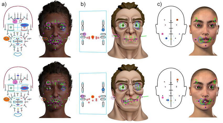
Fig. 6. Design Choices: a random control to vertex mapping produces
head symmetrically). Such controls should visually lie along their
visually meaningless and unusable UI layout (a); a layout based on
plane or axis of symmetry. We can enforce this by constraining the maximal displacement can result in visually cluttered and occluded UI
set of candidate layout vertices for to those that lie precisely on the elements (b); a layout based on minimal inter-element overlap creates
plane or axis of symmetry. In the absence of such vertices, the hard well spread but small UI elements (c); our approach jointly optimizes
constraint can be replaced with a function that penalizes the distance displacement, overlap, occlusion and symmetry criteria (d). Rig by
of a candidate vertex , from the plane or axis of symmetry. ©Antony Ward (3D World)
Global Deformations
While most rig parameters are manifested as localized shape defor-
mations, some rig parameters, such as one to customize gender may
deform all vertices of the shape significantly. Placing a UI element
for such a control locally on the shape can be misleading, and the UI
elements for such controls, such as the gender symbols in Figure 3(a),
are often presented as global and off-shape.
4 LAYOUT OPTIMIZATION ALGORITHM
The search for a layout (mapping rig controls to shape vertices)
∗ , that optimizes the design objectives in Section 3.3 is an instance
of an integer quadratic programming problem, known to be NP-Hard.
We first describe the quadratic programming formulation below, and Fig. 7. UI layouts can be optimized in 3D, or 2D from a given view.
then look at various pre-processing steps in Section 4.2, that reduce
represents the arc-length of the deformation trajectory of vertex
the computational complexity, and make the optimization practical
( ) controlled by UI element ( ) .
for state-of-the-art industrial rigs (Figure 2, 12).
Inter-element overlap is encoded as a symmetric matrix Q of size
× where is the inter-element overlap ( ( , )), where
4.1 Integer Quadratic Programming ( , ) computes an inter-element distance between element
We represent a candidate layout using an × binary matrix X ( ) mapped to vertex ( ) , and element ( ) mapped to
where = 1 iff control maps to vertex in (i.e. is ). Each vertex ( ) , and is a sigmoid function.
column of X is thus all zero elements and a single 1 in the row We calculate the inter-element distance to capture the difficulty
for vertex . We interchangeably write matrix X as a concatenation of selecting a point on a UI element due to spatial interference with
of rows into an ∗ column vector ® = [ 11, 12 ... −1, ] ⊺ . We another element. We thus first discretely sample any (uniform
use equivalent to ( −1)∗ + , and as equivalent to ( ) ( ) , parametric sampling): the UI element ( ) placed in 3D at shape
where ( ) = ( − 1)% + 1; ( ) = ( − ( ))/ + 1. vertex ( ) is sampled at points = { 1 ... }. We then
The maximal displacement objective for a given rig parameter compute the shortest distance from every point in to the point
configuration, is also encoded as an × column vector , ® where sample set for , and vice versa. The overall average of this
ACM Trans. Graph., Vol. 40, No. 4, Article 172. Publication date: August 2021.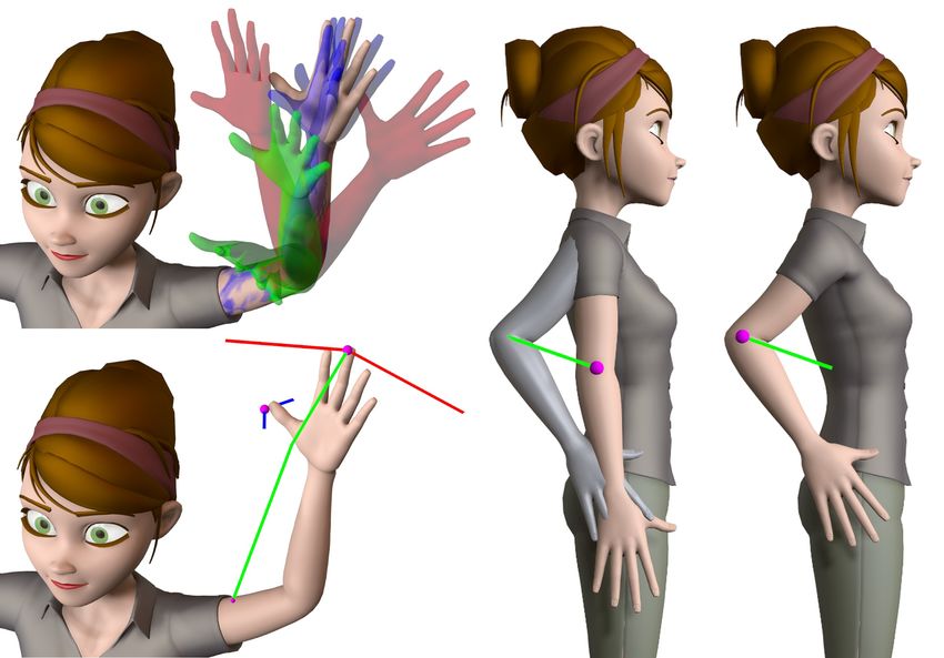
172:6 • Tagliasacchi et al.

 Input Prune Vertices Group Parameters Cluster Groups Downsample Vertices Solve Output
Deformable Model

 Rig Parameters

 Candidate Vertices in Yellow Groups in Blue Clusters in Purple

Fig. 8. Algorithm Overview: model vertices are first pruned based on design criteria to a candidate set of layout vertices for each rig parameter; the
parameters are then grouped and clustered based on the overlap and separation of their candidate vertices; candidate vertices in each cluster are
then sampled and used to compute an optimal layout using integer quadratic programming.

shortest distance is a symmetric distance measure ( , ). This
distance is then inverted to capture overlap using a function ( ):

 ( ) = − (1)
 1 + ( − )
where is the maximum overlap error, is the distance for which
gives /2 overlap, and scales how quickly the overlap penalty van-
ishes with increasing distance. In our implementation we used values
 = 5, = average edge length between adjacent shape vertices, and
 = 2. Fig. 9. FaceScape #393 ©The CITE LAB. Left to right: = 1 (maximal
 We cast these objectives as Equation 2 in a quadratic program: displacement), = 0.85 (default), = 0.4 (higher inter-element penalty),
 occlusion culling.
 1− ⊺
 min ® ® − ⊺ ® (2)
 ® 2
 = 1®
 s.t. A® (3) 4.2 Optimization Pre-processing
 We now discuss four independent grouping and pruning strategies
 ≤ 1®
 B® (4)
 that can radically reduce the number of variables we input to our
 ®1.. ∈ 0, 1 (5) quadratic layout optimization above.
 Pruning Layout Vertex Candidates
The relative importance of large displacements vs. inter-element
 Our optimization variables consider all vertices as layout map-
overlap in equation 2 can be controlled using (default = 0.85).
 ping candidates for parameter , yet many of these variables
Additional design objectives can be similarly added to equation 2
 would produce undesirable UI elements, and can be omitted from the
as quadratic or linear functions of . ® The goal of equation 3 is to
 pool of candidates. We thus use our design principles based on the
ensure that each of the controls gets mapped to exactly one of the
 following criteria, to produce a pruned set of candidate vertices and
 vertices. A is thus an × matrix. Row of A thus needs to
 associated variables ® :
isolate all variables for ∈ {1, .. }. Row of A is thus all 0’s
except for 1’s every elements, starting at index . Inequality 4 • Minimally deformed vertices: We prune variable if the
ensures that each of the vertices is mapped to by at most one of the length of ’s deformation trajectory for is below a thresh-
 controls. B is thus an × matrix. Row of B is filled with 0’s old (default set to the avg. length of all with non-zero tra-
except for a block of 1’s starting at column ∗ . Equation 5 ensures jectories). Deformation controls for which the minimally
that all variables in our quadratic program are binary. We found a deformed vertices are a small fraction (< 10%) of model ver-
quadratic program to be significantly faster and space efficient than tices are termed global. Such controls, like the gender control
a linear program that needs 2 additional variables to capture the in Figure 3(a), are often laid out adjacent to the shape, and can
inter-element overlap. optionally be removed from the optimization.
 Figure 9 further shows how our algorithm parameters can im- • Occluded Vertices: We prune variables whose deformation
pact the optimal rig UI layout, by varying the contributions of inter- trajectory for parameter is largely occluded by the model.
element overlap, and occlusion culling (particularly useful when We can also prune all , that are invisible from a given view.
many parameters are concentrated in local regions of high occlusion • Symmetric Deformations: For any parameter that symmetri-
like lip corners). cally deforms the shape, we can prune away all variables ,
 whose vertices do not lie on the plane/axis of symmetry.

ACM Trans. Graph., Vol. 40, No. 4, Article 172. Publication date: August 2021.
Optimizing UI Layouts for Deformable Face-Rig Manipulation • 172:7

Multi-Parameter Grouping Figure 11 shows the clustering of rig controls for different values
Rig parameters that deform very similar regions of the model are of . We use a default of = 2 to capture the typical upper/lower half
often complementary and may benefit from UI-elements like patches split on faces. We then compute the UI layout of each cluster of con-
and fans (Figure 5) that provide concurrent multi-parameter control trols in sequence, starting with the largest cluster. The UI elements
(Section 3.2). To detect possible parameter groupings of size (for a computed for former control clusters contribute fixed inter-element
 -parameter fan, default = 2 for a patch element), we initialize a distances as constraints for subsequent clusters and thus impact the
set of groups = [ 1 .. ], associated with with each rig parameter optimal layout when optimizing latter clusters. As shown in Fig-
 1 .. and a vertex set . that comprises candidate layout vertices ure 11, increasing the number of clusters can substantially improve
for after pruning. We then iteratively combine control groups efficiency, with minimal impact on the optimality of the control UI
and , that together can be represented by a -parameter fan (i.e. layout.
 | . ∩ . | Vertex Down-sampling
| ∪ | ≤ ), and whose Jacaard index , where = | . ∪ . | is

 High-end production models such as Figure 12 have upwards of 100K
the largest (i.e. we pick the , pair with he biggest > (default
 vertices. Rig deformations however, are mostly smooth, and regions
 = 0.85). We combine the two control groups by setting = ∪
 of neighboring vertices tend to have similar deformation trajectories.
and removing from . Likewise, ® is reduced to only retain
 We thus note that lower resolution proxies with a fraction of the
variables corresponding to vertices . ∩ . for combined controls
 original shape vertices, can produce near optimal UI layouts more
∈ ( ∪ ). The final set of parameter groups in , with its corre-
 efficiently (Figure 10). There are a number of ways to down-sample
sponding associated variables termed ® , can be further reduced
 the shape including random vertex sampling and model decimation
by clustering and down-sampling below, or serve as input to the
 that retains correspondence to a subset of the original shape vertices
quadratic optimization in Section 4.1.
 [Botsch et al. 2010]. Unlike typical mesh simplification that opti-
 mizes geometric fidelity to the original model, our sample importance
 criteria for a vertex favours large displacements (Equation 2). We
 thus perform a weighted random sampling on all ® variables ®

 in each cluster ∈∈ {1.. } above. The weights for each variable
 are associated with the displacement of its corresponding UI ele-
 ment. Our final set of variables down-sampled from ® is termed

 ® , ∈∈ {1.. }. Figure 10 shows that 5K+ vertex shapes can be
 down-sampled 5-10x before there is noticeable visual degradation in
 the control UI layout.
Fig. 10. UI layouts resulting from weighted random down-sampling
of vertices. The UI layout created using 20% of the model vertices is
qualitatively similar to the optimal layout (100%). Quality degrades with
visual clutter at 5% and inter-element overlap at 0.5% down-sampling.

Rig Parameter Clustering
The optimization space of candidate control layouts for model
vertices and rig controls grows exponentially with . We note
however, that many pairs of controls locally deform spatially distinct
regions of the model, and their respective UI elements are unlikely
to overlap. Partitioning the controls into such spatial clusters that can Fig. 11. Partitioning rig parameters significantly improves performance,
be independently optimized can thus greatly improve efficiency, with while preserving the visual quality of the UI layout. Computation time
little detriment to the overall UI layout. For example, UI elements (seconds) for 1 (164.43), 2 (13.6), 4 (11.41), and 6 (9.95) clusters.
for controls that deform the eyes and mouth are spatially distant in
Figure 1, 11, and could thus be optimized separately. 4.3 Implementation Details
 We thus implement a simple single-link clustering [Murtagh and We implemented our approach using a quadratic programming solver
Contreras 2012] on the rig control parameters where the distance in C++ using IBM CPLEX Optimizer library and control our mod-
metric between two clusters of parameters and : els in Autodesk Maya®2020. The results shown in the paper were
 Í Í Í Í
 ( , ) = ∈ ∈ ( , ), generated on a a Windows 10 machine with an Intel Core i5 3.6GHz
where , ∈ ® . In other words the distance between two clus- processor and NVIDIA®GeForce GTX 1080.
ters , is the total inter-element distance between all candidate
vertices for all pairs of controls belonging to and respectively.In 5 USER STUDY
practice, replacing the inter-element distance ( , ) by the We conducted a within subjects user study with 12 (8 amateur, 4
distance between vertices || − || produces similar results with bet- professional) participants (contacted via email), to evaluate the user
ter efficiency. Let = { 1 .. } be the resulting clusters that partition experience of our UI layouts. All participants had access to and
the set of rig controls. Consequently, variables ® are partitioned experience with Autodesk Maya®, in which the study was conducted.
 1 .. ® , where ∈ ® iff ∈ .
into ® Participants were identified as amateur/professional, specific to their

 ACM Trans. Graph., Vol. 40, No. 4, Article 172. Publication date: August 2021.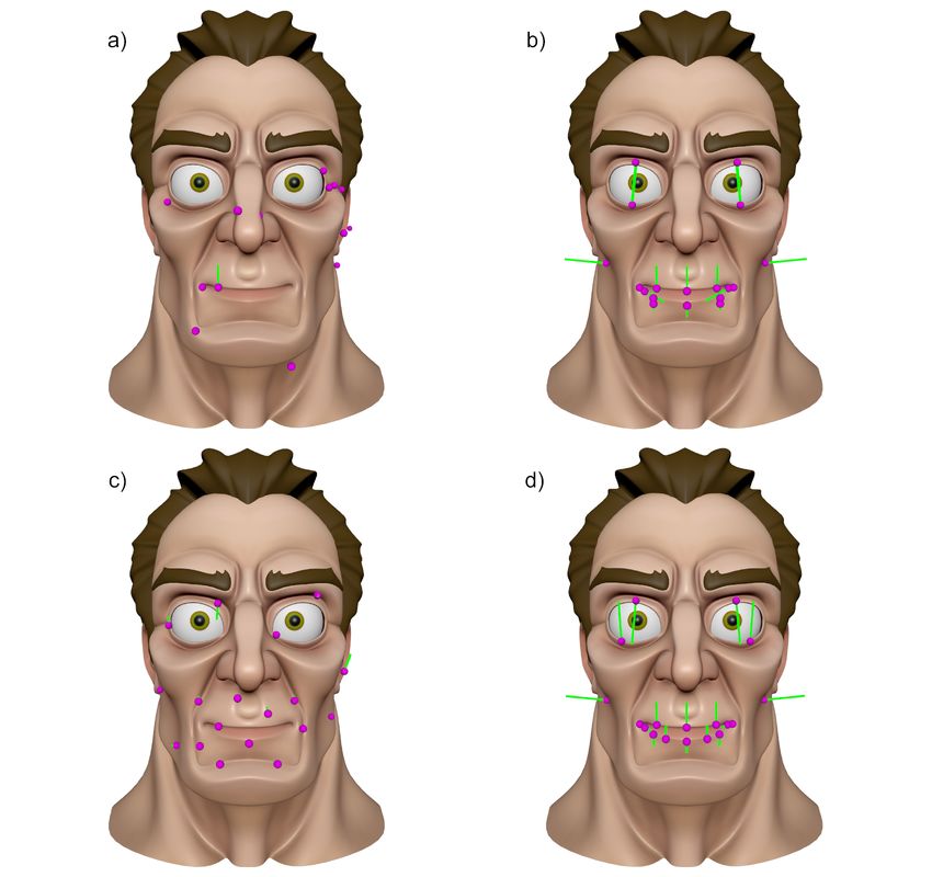
172:8 • Tagliasacchi et al.

 5.2 Analysis
 All subjects had some familiarity with Maya, and were able to com-
 plete the study without any reported difficulty. Our summary finding
 was that qualitatively, the overall user experience of the on-screen
 interfaces off-face and on-face (both with avg. 4 out of 5) was much
 better than the slider list (avg. 2.25 out of 5) (Figure 14(left)). Our
 on-face interface also scored highly (avg. 4.83 out of 5) on important
 questions like "The system gave me a feeling of directly manipu-
 lating the face?" (Figure 14(right)). Quantitatively, the study data
 corroborated user response: users were significantly slower with
 the slider list (46.87% of their total time on avg.), compared to the
 artist created off-face (25.62%), and our on-face interface (27.51%)
 (Figure 15(right)); while accuracy in matching target faces was sim-
 ilar, since users manipulated the face until satisfied. The list was
 marginally, but not consistently more accurate than the on-screen
Fig. 12. UI layout for a 85K vertex, 65 control Allan Henry face-rig
 interfaces, possibly due to finer control resolution of the longer list
©Weta Digital with neutral (left) and posed parameters (right).
 sliders (Figure 15(left)).
 Quantitative
 We measure expression accuracy in both rig parameter space (wt.
 error sq.) and model space (vtx. error sq.), as the squared difference
 between the values set by the user and the target expression. For
 reference, we report these error values as normalized relative to the
 difference between the target and neutral expression. In other words,
 the relative vertex error squared for a user set expression , target
Fig. 13. Expressions set by user 8 using the three compared inter-
 and neutral is: (|| − || 2 )/ (|| − || 2 ). The rig parameter
 Í Í
faces, for the common target expression.
 weight error is formulated similarly. Rig parameter weight errors bet-
 ter reflect perceptual changes in expression, but these weight errors
experience animating 3D face-rigs. While our in-situ layouts are
 can sometimes be misleading due to redundancy in rig parameter
designed to be used with direct manipulation [Lewis and Anjyo
 space (i.e. a user may create a similar visual expression to the tar-
2010] within a single interface (Figure 1(e)), our study disabled direct
 get by using a different rig parameter that produces a similar visual
manipulation to focus on a principled comparison of independent
 change in expression). Time spent on an interface is also normalized
parameter control: between a baseline slider list, an off-face animator
 as a % of total time taken by a user (Figure 15).
created gold-standard layout, and our on-face automatic UI layout,
 Figure 13 shows the complex common expression posed in block
for the model in Figure 13. We note that the artist layout and ours,
 order (list, on-face, off-face) by user 8. The actual time and %
could theoretically be interchangeably used as on or off face layouts.
 time spent on each interface in block order was (223s, 119s, 80s) and
 (17.5%, 9.3%, 6.3%), and the relative weight and vertex sq. errors
5.1 Experiment Setup and Protocol
 were (1.0, 1.01, 1.34) and (0.43, 0.47, 0.57), respectively. These
The study presented a subject with a posed target face, adjacent to statistics might suggest a learning effect with users getting quicker
a neutral face that was interactively manipulated by the subject us- with each block, and that accuracy depends on time spent with the
ing one of the above three interfaces, to visually match the target, interface. This however, was not a general trend: for eg., the same
until satisfied (Figure 13). Each participant was presented with the statistics for 12 (on-face, off-face, list) were (146s, 153s, 186s),
same sequence of 15 faces to match (3 interfaces * 5 faces). The (9.9%, 10.4%, 12.6%), (0.35, 1.36, 1.45) (0.33, 0.9, 0.62). In general
interfaces were tested in order (one of 6 permutations of list, off-face for the common expression, overall participants spent 36% and 12%
and on-face), fully counter-balanced across the 12 subjects. 12 of the more time using list and off-face, than our interface.
15 faces were unique and of varying complexity (activating 1-13 rig Judging, from user comments, the off-screen parameter list takes
parameters) spread across the three interfaces tested. One expression consistently longer to find and manipulate than on-screen controls
(13 activated parameters) was repeated for all the 3 interfaces (Fig- ("moving back and forth between the face and the slider GUI takes
ure 13). Participants were presented with the faces side-by-side in a time" 8, "slider attribute editor interface does not scale, need to
frontal view, but were free to manipulate the camera, as desired. hunt for controls in a scroll list and controls are sometimes not in list
 The study instructions and testing itself were driven from a UI close to similar ones" 6, "when working with an animated face in a
control panel within Maya. Each interface test started with 2 sim- dynamic scene it is better to have controls close at hand", 7 ).
ple expressions (1-2 rig parameters) followed by 3 more complex The marginally better accuracy of the slider list could be due to
expressions (6+ rig parameters). The study was run uncontrolled, resolution ("one advantage of the slider interface is that it does seem
and completed on average in 28 minutes by participants remotely in to provide finer resolution when interacting with the controls" 7).
Maya. After the study participants filled-out an online questionnaire The resolution of on-screen controls can be made finer by zooming
on their experience using the three interfaces (Figure 14).

ACM Trans. Graph., Vol. 40, No. 4, Article 172. Publication date: August 2021.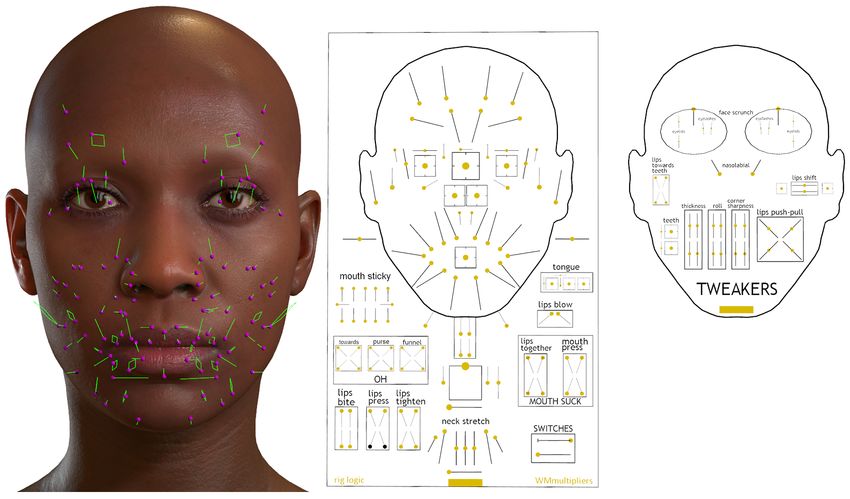
Optimizing UI Layouts for Deformable Face-Rig Manipulation • 172:9

 – "Precise and local control with direct face grabbing is a problem,
 and the on-face sliders complement direct manipulation beautifully.
 I would love to see them work together." 8.
 Our layouts are indeed designed and already implemented to be
 used in conjunction with direct manipulation (Figure 1(e)).
 Face specific (Critical)
 – "It would be useful to show the area of influence when you select
 the control to give a sense of what area is affected (similar to
 skin weights map). Or the inverse: clicking anywhere on the mesh
 would highlight which controls have influence on that area." 5.
 – "All 3 interfaces could benefit from symmetric control toggle." 6.
Fig. 14. User Study: overall experience with the three interfaces (left); Model occlusion (Critical)
questions pertaining to the on-face UI (right).
 Many users found that on-face visually obscured evaluating the ma-
 nipulated expression, suggesting off-face transport, and UI element
 toggles/transparency as solutions:
 – "Perhaps working on a duplicate copy of the face will be better?
 So your manipulations feel direct, but you can still see the actual
 result well." 2 (also 1).
 – "It would be useful to be able to move the off-face controls on-face
 and vice versa for the on-face sliders." 7.
 – "It felt the most natural to use the on-the-face slider layout, but
 I wish I could toggle the visibility of the sliders in this format."
 3 (also suggested by 5, 10 and 6 actually "added a toggle to
 hide/show them").
 – "On-face sliders need to be very transparent but if not visually
 occluding can save time keeping the focus on the face." 11. (also
 8 did likewise "I made the on-face slider shader very transparent
 so I could grab them and evaluate the facial pose simultaneously.").
Fig. 15. User Study: avg. relative weight|vertex sq. error (left
top|bottom) and % time the users spent on the three interfaces (right).

into the model but we feel users did not manipulate the camera much 6 RESULTS AND DISCUSSION
("...this fixed model and camera test setting" 7). Direct Shape|Parameter Control Interface
Qualitative While the user study (Section 5) only compared independent parame-
Figure 14(left) shows that our interface was well-received, relative to ter control using our on-face UI layout with an off-face hand-crafted
the list and off-face interfaces. The responses to questions (below) UI layout and a baseline slider list, our layouts provide a homoge-
focused on our interface were also largely positive Figure 14(right): neous interface to complementary direct-shape and direct-parameter
– The system allowed me to create expressions easily. manipulation (see video and Figure 1(e)).
– Changing slider values caused unexpected results. Gallery of Rig UI layouts
– The layout felt cluttered. Figures 1,2,17 show a number of rigs, for which our approach pro-
– Sliders were placed appropriately with respect to their deformed duced UI layouts that matched the aesthetic and functional choices
 regions. made by artists in hand-crafting UI layouts for the rig. Figures 9,12,18
– The system gave me a feeling of directly manipulating the face. show further UI layouts for a number of face rigs for which we had
We also received a wealth of both positive and critical feedback: no hand-crafted comparison.
General (Positive) Table 1 shows the input vertex and control complexity, algorith-
– "I really liked the on-the-face slider a lot." 4. mic parameters, and computation times, for all the face-rigs shown
– "Am not an expert on faces but such an interface (on-face) can be in the paper. While our core optimization algorithm (Section 4.1)
 very useful for any on-object parameter interaction." 11. can be exponential in complexity, the pruning, grouping, clustering
– "The on-face patches are very cool and it would be great to see and down-sampling stages in (Section 4.2), allow us in practice to
 more such coupled controls". "Maybe this grouping can even be compute rig UI layouts for high-end face rigs with over a hundred rig
 dynamic, where I select two or more controls..." 8. Animator critique
Direct Manipulation (Positive) We consulted a professional animator to critique the rig layouts in
– "On-face sliders are great and direct" 6. Figures 17, 18. He found our rig UI layouts to be compelling, and
– "The on-face sliders feels very direct because all the sliders move was easily able to refine our layout aesthetics in Figure 1(f). He fur-
 and stay stuck to the face. It would be cool to augment the on-face ther commented on various aspects of our problem space, opining
 slider interaction with directly pulling on parts of the face." 7. that our interface was (or could be):

 ACM Trans. Graph., Vol. 40, No. 4, Article 172. Publication date: August 2021.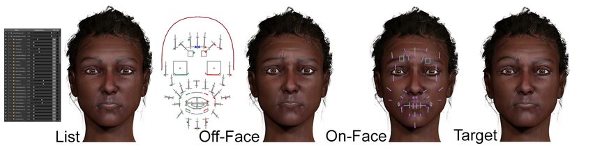
172:10 • Tagliasacchi et al.

discoverable and could be manipulated instinctively, without instruc- Model Vertex Count Controls Clusters Sample % Time (s)
tion or labels, in contrast to a baseline list of parameter names; Dakar Valley Girl 5064 47 2 100/20/5 249/45/11
immersively direct keeping focus on the face in context with UI Head Rig 1186 26 2 20
Optimizing UI Layouts for Deformable Face-Rig Manipulation • 172:11

Fig. 17. Hand-crafted layouts (left) compared to our rig UI layouts (right). a) Dakar Valley Girl ©Chris Landreth b) Rig by ©Antony Ward (3D World)
c) Animatable Digital Double of Louise by Eisko© ( www.eisko.com )

throughput and quality of animation produced. Beyond character ani- ACM SIGGRAPH/Eurographics Symposium on Computer Animation. Eurographics
mation, we hope our work will inspire future research in automatic Association, 103–112.
 Ozan Cetinaslan and Verónica Orvalho. 2018. Direct Manipulation of Blendshapes
creation of in-situ user interfaces. Using a Sketch-Based Interface. In Proceedings of the 23rd International ACM
Acknowledgments Conference on 3D Web Technology (Poznań, Poland) (Web3D ’18). Association
 for Computing Machinery, New York, NY, USA, Article 14, 10 pages. https:
We would like to thank Chris Landreth (JALI Research) and Steve //doi.org/10.1145/3208806.3208811
Cullingford (Weta Digital) for providing us with facial rigs, anima- Pif Edwards, Chris Landreth, Mateusz Popławski, Robert Malinowski, Sarah Watling,
tions, and invaluable feedback. We are also grateful to our user study Eugene Fiume, and Karan Singh. 2020. JALI-Driven Expressive Facial Animation
 and Multilingual Speech in Cyberpunk 2077. In Special Interest Group on Computer
participants, and to Metahuman (Epic Games), CGTarian, Antony Graphics and Interactive Techniques Conference Talks (Virtual Event, USA) (SIG-
Ward (3D World), CITE LAB, Eisko, Mery Project, and Chad Vernon GRAPH ’20). Association for Computing Machinery, New York, NY, USA, Article
for face rigs. This research was supported by NSERC. 60, 2 pages. https://doi.org/10.1145/3388767.3407339
 Rosenberg Ekman. 1997. What the face reveals: Basic and applied studies of spontaneous
 expression using the Facial Action Coding System (FACS). Oxford University Press,
REFERENCES USA.
 Krzysztof Z Gajos, Mary Czerwinski, Desney S Tan, and Daniel S Weld. 2006. Exploring
Rinat Abdrashitov, Fanny Chevalier, and Karan Singh. 2020. Interactive Exploration and
 the design space for adaptive graphical user interfaces. In Proceedings of the working
 Refinement of Facial Expression Using Manifold Learning. In Proceedings of the
 conference on Advanced visual interfaces. 201–208.
 33rd Annual ACM Symposium on User Interface Software and Technology (Virtual
 Sarah Gibson, Paul Beardsley, Wheeler Ruml, Thomas Kang, Brian Mirtich, Joshua
 Event, USA) (UIST ’20). Association for Computing Machinery, New York, NY,
 Seims, William Freeman, Jessica Hodgins, Hanspeter Pfister, Joe Marks, et al. 1997.
 USA, 778–790. https://doi.org/10.1145/3379337.3415877
 Design galleries: A general approach to setting parameters for computer graphics and
Maneesh Agrawala, Wilmot Li, and Floraine Berthouzoz. 2011. Design Principles
 animation. (1997).
 for Visual Communication. Commun. ACM 54, 4 (April 2011), 60–69. https:
 Michael Gleicher. 1992. Integrating constraints and direct manipulation. In Symposium
 //doi.org/10.1145/1924421.1924439
 on Interactive 3 D Graphics: Proceedings of the 1992 symposium on Interactive 3 D
Eric Allen and Kelly L. Murdock. 2008. Body Language: Advanced 3D Character
 graphics, Vol. 1992. 171–174.
 Rigging (pap/cdr ed.). SYBEX Inc., USA.
 Martin Guay, Marie-Paule Cani, and Rémi Ronfard. 2013. The line of action: an intuitive
Norman I Badler, Brian A Barsky, and David Zeltzer. 1990. Making Them Move:
 interface for expressive character posing. ACM Transactions on Graphics (TOG) 32,
 Mechanics, Control & Animation of Articulated Figures. Routledge.
 6 (2013), 1–8.
Stephen W. Bailey, Dalton Omens, Paul Dilorenzo, and James F. O’Brien. 2020. Fast
 Yuki Koyama, Daisuke Sakamoto, and Takeo Igarashi. 2014. Crowd-powered parameter
 and Deep Facial Deformations. ACM Trans. Graph. 39, 4, Article 94 (July 2020),
 analysis for visual design exploration. In Proceedings of the 27th annual ACM
 15 pages. https://doi.org/10.1145/3386569.3392397
 symposium on User interface software and technology. ACM, 65–74.
Eric Allan Bier. 1987. Skitters and jacks: interactive 3D positioning tools. In Proceedings
 Paul G Kry, Doug L James, and Dinesh K Pai. 2002. Eigenskin: real time large de-
 of the 1986 workshop on Interactive 3D graphics. ACM, 183–196.
 formation character skinning in hardware. In Proceedings of the 2002 ACM SIG-
Mario Botsch, Leif Kobbelt, Mark Pauly, Pierre Alliez, and Bruno Lévy. 2010. Polygon
 GRAPH/Eurographics symposium on Computer animation. 153–159.
 mesh processing. CRC press.
 Manfred Lau, Jinxiang Chai, Ying-Qing Xu, and Heung-Yeung Shum. 2009. Face poser:
Eric Brochu, Tyson Brochu, and Nando de Freitas. 2010. A Bayesian interactive
 Interactive modeling of 3D facial expressions using facial priors. ACM Transactions
 optimization approach to procedural animation design. In Proceedings of the 2010

 ACM Trans. Graph., Vol. 40, No. 4, Article 172. Publication date: August 2021.
172:12 • Tagliasacchi et al.

Fig. 18. Rig UI layouts on models for which no hand-crafted comparison is available. a) Dan b) Angela c) Prague Boy d) Clara e) Pidoras all by
©Chris Landreth f) Mery Project by ©{José Manuel García Alvarez and Antonio Francisco Méndez Lora} g) Nico by ©Chad Vernon (chandmv).

 on Graphics (TOG) 29, 1 (2009), 3. Mike Seymour. 2016. Put your (digital) game face on. (2016). https://www.fxguide.
Binh H. Le, Mingyang Zhu, and Zhigang Deng. 2013. Marker Optimization for Facial com/fxfeatured/put-your-digital-game-face-on/
 Motion Acquisition and Deformation. IEEE Transactions on Visualization and Mike Seymour. 2018. Making Thanos Face the Avengers. (2018). https://www.fxguide.
 Computer Graphics 19, 11 (Nov. 2013), 1859–1871. https://doi.org/10.1109/TVCG. com/fxfeatured/making-thanos-face-the-avengers/
 2013.84 Mike Seymour. 2019. Bebyface in Bebylon. (2019). https://www.fxguide.com/
John P Lewis and Ken-ichi Anjyo. 2010. Direct manipulation blendshapes. IEEE fxfeatured/bebyface-in-bebylon/
 Computer Graphics and Applications 30, 4 (2010), 42–50. Karan Singh and Eugene Fiume. 1998. Wires: a geometric deformation technique. In
Hao Li, Jihun Yu, Yuting Ye, and Chris Bregler. 2013. Realtime Facial Animation with Proceedings of the 25th annual conference on Computer graphics and interactive
 On-the-Fly Correctives. ACM Trans. Graph. 32, 4, Article 42 (July 2013), 10 pages. techniques. 405–414.
 https://doi.org/10.1145/2461912.2462019 Marc P Stevens, Robert C Zeleznik, and John F Hughes. 1994. An architecture for an
José Carlos Miranda, Xenxo Alvarez, João Orvalho, Diego Gutierrez, A Augusto Sousa, extensible 3D interface toolkit. In Proceedings of the 7th annual ACM symposium on
 and Verónica Orvalho. 2011. Sketch express: facial expressions made easy. In User interface software and technology. 59–67.
 Proceedings of the Eighth Eurographics Symposium on Sketch-Based Interfaces and Tanasai Sucontphunt, Zhenyao Mo, Ulrich Neumann, and Zhigang Deng. 2008. Interac-
 Modeling. ACM, 87–94. tive 3D facial expression posing through 2D portrait manipulation. In Proceedings of
Niloy J. Mitra, Mark Pauly, Michael Wand, and Duygu Ceylan. 2012. Symmetry in 3D graphics interface 2008. Canadian Information Processing Society, 177–184.
 Geometry: Extraction and Applications. In EUROGRAPHICS State-of-the-art Report. Jerry O Talton, Daniel Gibson, Lingfeng Yang, Pat Hanrahan, and Vladlen Koltun.
 https://doi.org/10.1111/cgf.12010 2009. Exploratory modeling with collaborative design spaces. ACM Transactions on
Fionn Murtagh and Pedro Contreras. 2012. Algorithms for hierarchi- Graphics-TOG 28, 5 (2009), 167.
 cal clustering: an overview. WIREs Data Mining and Knowledge J. Rafael Tena, Fernando De la Torre, and Iain Matthews. 2011. Interactive Region-Based
 Discovery 2, 1 (2012), 86–97. https://doi.org/10.1002/widm.53 Linear 3D Face Models. ACM Trans. Graph. 30, 4, Article 76 (July 2011), 10 pages.
 arXiv:https://onlinelibrary.wiley.com/doi/pdf/10.1002/widm.53 https://doi.org/10.1145/2010324.1964971
Victor Navone. 2020. Facial Animation for Feature Animated Films: Animating stylized Ayush Tewari, Michael Zollöfer, Hyeongwoo Kim, Pablo Garrido, Florian Bernard,
 facial expressions. https://www.thegnomonworkshop.com/tutorials/facial-animation- Patrick Perez, and Theobalt Christian. 2017. MoFA: Model-based Deep Convolu-
 for-feature-animated-films (2020). tional Face Autoencoder for Unsupervised Monocular Reconstruction. In The IEEE
Jason Osipa. 2010. Stop Staring: Facial Modeling and Animation Done Right (3rd ed.). International Conference on Computer Vision (ICCV).
 SYBEX Inc., USA. Thibaut Weise, Sofien Bouaziz, Hao Li, and Mark Pauly. 2011. Realtime performance-
Rick Parent. 2012. Computer animation: algorithms and techniques. Newnes. based facial animation. In ACM transactions on graphics (TOG), Vol. 30. ACM.
Ryan Schmidt, Karan Singh, and Ravin Balakrishnan. 2008. Sketching and composing Lance Williams. 1990. Performance-driven facial animation. In ACM SIGGRAPH
 widgets for 3d manipulation. In Computer graphics forum, Vol. 27. Wiley Online Computer Graphics, Vol. 24. ACM, 235–242.
 Library, 301–310. Eduard Zell, JP Lewis, Junyong Noh, Mario Botsch, et al. 2017. Facial retargeting with
Thomas W Sederberg and Scott R Parry. 1986. Free-form deformation of solid geometric automatic range of motion alignment. ACM Transactions on Graphics (TOG) 36, 4
 models. In Proceedings of the 13th annual conference on Computer graphics and (2017), 154.
 interactive techniques. 151–160.

ACM Trans. Graph., Vol. 40, No. 4, Article 172. Publication date: August 2021.
You can also read