Owner's Guide and Installation Instructions - Rheem
←
→
Page content transcription
If your browser does not render page correctly, please read the page content below
Owner’s Guide
                                     and
                          Installation Instructions

                             Raypak Water Heaters

                                        Models                                  Types
                          B0538           B0992*              B0972
                                                                              NCO, NCM,
                          B0658*          B1182               B1142
                                                                                *PCM
                          B0768           B1292               B1242
                          B0868           B1412*              B1362
                                          B1722               B1662
                                          B1922*              B1852
                                          B2214               B2004
                                          B2634               B2404
                                          B3164               B2804
                                          B3694               B3304
                                          B4224               B3804

                     This water heater must be installed and serviced by a qualified person.
      This water heater must be certified in accordance with AS3814 before being brought into service
                               Please leave this guide with a responsible officer.

Revision Date: Mar 2021                              1                                           96507422-L
Notice to Victorian Customers from the
                                            Victorian Building Authority

                      This water heater must be installed by a licensed person as required by
                                         The Victorian Building Act 1993

           Only a licensed person will give you a Compliance Certificate, showing that the work complies
           with all the relevant standards. Only a licensed person will have insurance protecting their
           workmanship for 6 years. Make sure you use a licensed person to install this water heater and
           ask for your Compliance Certificate.

               Warning: Upon completion of the installation and commissioning of the water heater, leave
           this guide with the householder or a responsible officer. DO NOT leave this guide inside of the
           cover of the water heater, as it may interfere with the safe operation of the water heater or ignite
           when the water heater is turned on.

                   Date of installation:

                             Model Nº:

                             Serial Nº:

                          Installed by:

                      Purchased from:

                                                     PATENTS
                   This water heater may be protected by one or more patents or registered designs.

                                 ® Registered trademark of Rheem Australia Pty Ltd.
                                     ™ Trademark of Rheem Australia Pty Ltd.

Revision Date: Mar 2021                                     2                                                     96507422-L
CONTENTS

              HOUSEHOLDER OR RESPONSIBLE OFFICER – We recommend you read pages 6 to 12.

                                  The other pages are intended for the installer but may be of interest

   Contents ..................................................................................................................................................................3
   Warranty ..................................................................................................................................................................4
   Raypak Water Heater Warranty – Australia Only ....................................................................................................4
   About Your Water Heater ........................................................................................................................................6
   How Your Water Heater Works ...............................................................................................................................9
   Save A Service Call ...............................................................................................................................................10
   Regular Care .........................................................................................................................................................12
   Installation ..............................................................................................................................................................13
   Connections – Plumbing ........................................................................................................................................17
   Connections – Electrical ........................................................................................................................................26
   Location Of Controls ..............................................................................................................................................39
   Safety Precautions.................................................................................................................................................40
   Commissioning ......................................................................................................................................................41
   Operating The Water Heater .................................................................................................................................44
   Component Checks & Adjustment Procedures .....................................................................................................45
   Temperature Control..............................................................................................................................................49
   Service Procedures ...............................................................................................................................................57
   Water Supplies ......................................................................................................................................................58
   Dimensions and Technical Data ............................................................................................................................59

Revision Date: Mar 2021                                                               3                                                                          96507422-L
WARRANTY

                RAYPAK WATER HEATER WARRANTY – AUSTRALIA ONLY

                                          RAYPAK WATER HEATER MODELS B0538-B4224

                                                  1. THE RHEEM WARRANTY – GENERAL
1.1 This warranty is given by Rheem Australia Pty Limited ABN 21 098 823 511 of 1 Alan Street, Rydalmere New South Wales.
1.2 Rheem offer a trained and qualified national service network who will repair or replace components at the address of the water heater subject
     to the terms of the Rheem warranty. Rheem Service, in addition can provide preventative maintenance and advice on the operation of your
     water heater. The Rheem Service contact number is available 7 days a week on 131031 with Service personnel available to take your call from
     8am to 8pm daily (hours subject to change).
1.3 For details about this warranty, you can contact us on 131031 or by email at warrantyenquiry@rheem.com.au (not for service bookings)
1.4 The terms of this warranty and what is covered by it are set out in sections 2 and 3 and apply to water heaters manufactured after
    1st February 2015.
1.5 If a subsequent version of this warranty is published, the terms of that warranty and what is covered by it will apply to water heaters manufactured
     after the date specified in the subsequent version.

                                  2. TERMS OF THE RHEEM WARRANTY AND EXCLUSIONS TO IT
2.1 The decision of whether to repair or replace a faulty component is at Rheem’s sole discretion.
2.2 If you require a call out and we find that the fault is not covered by the Rheem warranty, you are responsible for our standard call out charge. If
    you wish to have the relevant component repaired or replaced by Rheem, that service will be at your cost.
2.3 Where a failed component or cylinder is replaced under this warranty, the balance of the original warranty period will remain effective. The
    replacement does not carry a new Rheem warranty.
2.4 Where the water heater is installed outside the boundaries of a metropolitan area as defined by Rheem or further than 25 km from either a
    regional Rheem branch office or an Accredited Rheem Service Agent's office, the cost of transport, insurance and travelling between the nearest
    branch office or Rheem Accredited Service Agent’s office and the installed site shall be the owner’s responsibility.
2.5 Where the water heater is installed in a position that does not allow safe or ready access, the cost of that access, including the cost of additional
    materials handling and/or safety equipment, shall be the owner’s responsibility. In other words, the cost of dismantling or removing cupboards,
    doors or walls and the cost of any special equipment to bring the water heater to floor or ground level or to a serviceable position is not covered
    by this warranty.
2.6 This warranty only applies to the original and genuine Rheem water heater in its original installed location and any genuine Rheem replacement
    parts.
2.7 The Rheem warranty does not cover faults that are a result of:
    a) Accidental damage to the water heater or any component (for example: (i) Acts of God such as floods, storms, fires, lightning strikes and
         the like; and (ii) third party acts or omissions).
    b) Misuse or abnormal use of the water heater.
    c) Installation not in accordance with the Owner’s Guide and Installation Instructions or with relevant statutory and local requirements in the
         State or Territory in which the water heater is installed.
    d) Connection at any time to a water supply that does not comply with the water supply guidelines as outlined in the Owner’s Guide and
         Installation Instructions.
    e) Repairs, attempts to repair or modifications to the water heater by a person other than Rheem Service or a Rheem Accredited Service
         Agent.
    f) Faulty plumbing or faulty power supply.
    g) Failure to maintain the water heater in accordance with the Owner's Guide and Installation Instructions.
    h) Transport damage.
    i) Fair wear and tear from adverse conditions (for example, corrosion).
    j) Cosmetic defects.
2.8 Subject to any statutory provisions to the contrary, this warranty excludes any and all claims for damage to furniture, carpet, walls, foundations
    or any other consequential loss either directly or indirectly due to leakage from the water heater, or due to leakage from fittings and/ or pipe
    work of metal, plastic or other materials caused by water temperature, workmanship or other modes of failure.
2.9 If the water heater is not sized to supply the hot water demand in accordance with the guidelines in the Rheem water heater literature, any
    resultant fault will not be covered by the Rheem warranty.

Revision Date: Mar 2021                                                    4                                                                96507422-L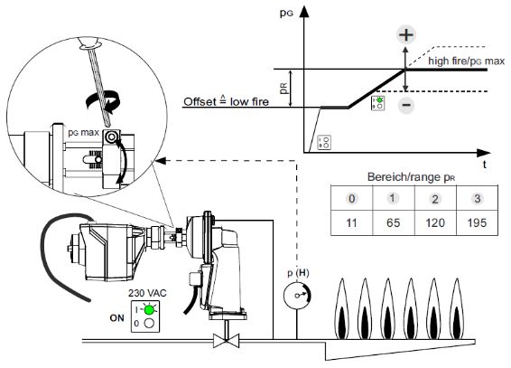
3. WHAT IS COVERED BY THE RHEEM WARRANTY FOR THE WATER HEATERS DETAILED IN THIS DOCUMENT
3.1 Rheem will repair or replace a faulty component of your water heater if it fails to operate in accordance with its specifications as follows:

                                                   The period in which the fault must
           What components are covered                                                                 What coverage you receive
                                                     appear in order to be covered
                                                                                            Repair and/or replacement of the faulty
                   All components                                 Year 1
                                                                                            component, free of charge, including labour.

                                                                                            Replacement heat exchanger or tube bundle, free
           Heat Exchanger / Tube Bundle                         Years 2 to 5                of charge. Installation and repair labour costs are
                                                                                            the responsibility of the owner.

                                   4. ENTITLEMENT TO MAKE A CLAIM UNDER THIS WARRANTY
4.1 To be entitled to make a claim under this warranty you need to:
    a) Be the owner of the water heater or have consent of the owner to act on their behalf.
    b) Contact Rheem Service without undue delay after detection of the defect and, in any event, within the applicable warranty period.
4.2 You are not entitled to make a claim under this warranty if your water heater:
    a) Does not have its original serial numbers or rating labels.
    b) Is not installed in Australia.

                                         5. HOW TO MAKE A CLAIM UNDER THIS WARRANTY
5.1 If you wish to make a claim under this warranty, you need to:
    a) Contact Rheem on 131031 and provide owner’s details, address of the water heater, a contact number and date of installation of the water
         heater or if that’s unavailable, the date of manufacture and serial number (from the rating label on the water heater).
    b) Rheem will arrange for the water heater to be tested and assessed on-site.
    c) If Rheem determines that you have a valid warranty claim, Rheem will repair or replace the water heater in accordance with this warranty.
5.2 Any expenses incurred in the making of a claim under this warranty will be borne by you.

                                                  6. THE AUSTRALIAN CONSUMER LAW
6.1 Our goods come with guarantees that cannot be excluded under the Australian Consumer Law. You are entitled to a replacement or refund for
    a major failure and for compensation for any other reasonably foreseeable loss or damage. You are also entitled to have the goods repaired or
    replaced if the goods fail to be of acceptable quality and the failure does not amount to a major failure.
6.2 The Rheem warranty (set out above) is in addition to any rights and remedies that you may have under the Australian Consumer Law.

Note: Every care has been taken to ensure accuracy in preparation of this publication. No liability can be accepted for any
consequences, which may arise as a result of its application

                                RHEEM AUSTRALIA PTY LTD, A.B.N. 21 098 823 511, www.rheem.com.au

                                              RAYPAK AUSTRALIA PTY LTD A.B.N. 65 078 743 414

                                  For Service Telephone 131 031 AUSTRALIA or 0800 657 335 NEW ZEALAND

Revision Date: Mar 2021                                                    5                                                               96507422-L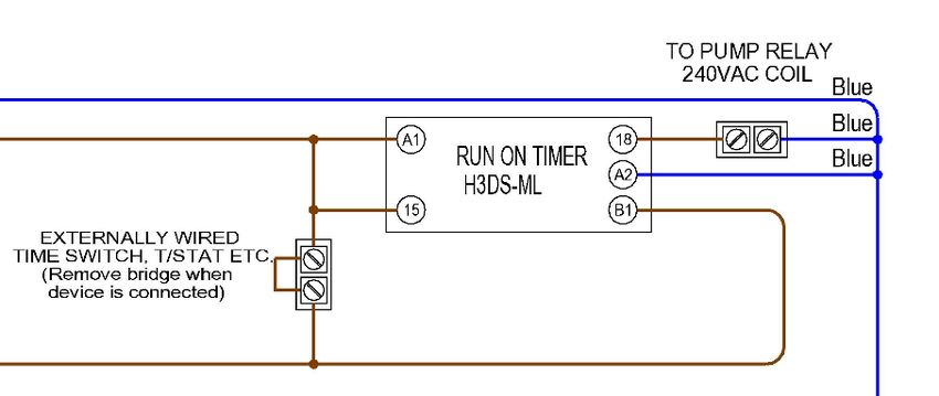
ABOUT YOUR WATER HEATER
ABOUT YOUR WATER HEATER
WATER HEATER APPLICATION
This water heater is designed for the purpose of heating potable water or hydronic heating applications. Its use in an
application other than this may shorten its life.
MODEL TYPE
Congratulations for choosing a Raypak® water heater. Raypak water heaters are suitable for either indoor or outdoor
installation depending on the model chosen.
The operation of the water heater depends on the application. Typically for hot water applications a water heater with
‘On/Off’ operation will be installed. For mechanical heating or process applications a water heater with ‘modulating’
operation will be installed.
A limited range of models suitable for use on propane gas is available. These are supplied with modulating
gas valves only and are suitable for use in hot water applications as well as mechanical heating or process
applications.
A spare 850 kPa (125 PSI) pressure relief valve is supplied inside the water heater casing for use in mains
pressure water heating applications. The fitted 415 kPa (60 PSI) pressure relief valve should be removed and
the higher pressure rating valve installed before the water heater is operated in domestic hot water
applications.
HOW HOT SHOULD THE WATER BE?
The water heater features an adjustable electronic thermostat,
which allows the most suitable temperature for the application to
be chosen.
To meet the requirements of the National Plumbing Standard the
temperature of the stored water for hot water applications must HOT WATER INSTALLATIONS
Minimum recommended stored
not be below 60°C. water temperature
HOTTER WATER INCREASES THE RISK OF SCALD INJURY
This water heater can deliver water at temperatures which can HOT WATER INSTALLATIONS
cause scalding. Check the water temperature before use, such Maximum recommended
as when entering a shower or filling a bath or basin, to ensure it supply temperature to
is suitable for the application and will not cause scald injury. bathrooms and ensuites
We recommend and it may be required by regulations that an
approved temperature limiting device be fitted into the hot water
piping to the bathroom and ensuite when this water heater is
installed. This will keep the water temperature below 50C at the
bathroom and ensuite. The risk of scald injury will be reduced
whilst still allowing hotter water to the kitchen and laundry.
TEMPERATURE ADJUSTMENT
The electronic thermostat temperature will have been set by the installer to suit the application, adjustment should
not be required. Consult your installer before making any adjustment to the electronic thermostat settings.
GENERAL WARNINGS
Warning: This water heater is only intended to be operated by persons who have the experience or the knowledge
and the capabilities to do so. This water heater is not intended to be operated by persons (including children) with
reduced physical, sensory or mental capabilities, or lack of experience and knowledge.
Warning: Children should be supervised to ensure they do not interfere with the water heater.
Warning: The water heater uses 240 Volt AC electrical power for operation of the control systems. The removal
of the access cover(s) will expose 240 V wiring. Covers must only be removed by an authorised or qualified person.
6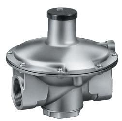
ABOUT YOUR WATER HEATER
SAFETY
For your safety do not operate this water heater before reading this instruction booklet.
This water heater is supplied with an electronic thermostat, high limit thermostat and a pressure relief valve. These
devices must not be tampered with or removed. The water heater must not be operated unless each of these devices
is fitted and is in working order.
Improper installation, adjustment, alteration, service or maintenance can cause injury or property damage. For
assistance or additional information consult your Raypak distributor, qualified installer, or Rheem® Service agent.
The warranty can become void if relief valves or other safety devices are tampered with or if the installation
is not in accordance with these instructions.
DO NOT store flammable or combustible materials near the water heater.
Flammable liquids (such as petrol), newspapers and similar articles must be
kept well away from the water heater and the draught diverter or flue terminal.
DO NOT use aerosols, stain removers and household chemicals near the
water heater whilst it is working. Gases from some aerosol sprays, stain
removers and household chemicals become corrosive when drawn into a flame.
DO NOT store swimming pool chemicals, household cleaners, etc., near
the water heater.
DO NOT place anything on top of the water heater or in contact with the flue
terminal. Ensure the flue terminal is not obstructed in any way at any time.
DO NOT use Propane / Butane gas mixtures in a Propane model. A Propane model is designed to operate on
Propane only. The use of Propane / Butane mixture, such as automotive LPG fuel, in a Propane model is unsafe
and can cause damage to the water heater.
DO NOT operate with panels, covers or guards removed from the water heater.
DO NOT enclose this water heater (applies to external installations only).
Do not use the water heater if any part has been under water. Immediately call Rheem Service or Accredited service
Agent to arrange for an inspection.
TO TURN ON THE WATER HEATER
Warning: If you smell gas do not attempt to turn on the water heater.
Fill the system with water (refer to “To Fill the Water Heater” on page 44).
Open the gas isolation valve fully at the inlet to the water heater.
Switch on the electrical supply at the water heaters isolation switch. NOTE: If the water heater is correctly
installed, this will also activate the circulating pump.
The water heater will operate automatically when a call for heat occurs.
WHAT TO DO IF YOU SMELL GAS?
DO NOT try to light any gas appliance.
DO NOT touch any electrical switch.
TURN OFF the gas supply at the gas meter immediately, call your gas supplier or licensed gasfitter.
NOTE: Some gases are heavier than air and it may be necessary to check for gas leaks at floor level.
TO TURN OFF THE WATER HEATER
If it is necessary to turn off the water heater:
Switch off the electrical supply at the water heaters isolation switch. NOTE: If the water heater is correctly
installed, this will also shut down the circulating pump.
Close the gas isolation valve at the inlet to the water heater.
Close the cold water isolation valve at the inlet to the water heater.
Close the isolation valves on the cold and hot water branches to shut down an individual water heater in a bank
(water heating applications only).
7ABOUT YOUR WATER HEATER
HOW DO I KNOW IF THE WATER HEATER IS INSTALLED CORRECTLY?
Installation requirements are detailed in the “Installation” section on pages 13 to 17. The water heater must be
installed:
by a qualified person, and
in accordance with the installation instructions, and
in compliance with Standards AS/NZS 3500.4, AS 5601 or AS/NZS 5601.1, as applicable under local
regulations, and all local codes and regulatory authority requirements.
In New Zealand, the installation must also conform to NZS 5261, as applicable under local regulations, and the
New Zealand Building Code.
DOES THE WATER CHEMISTRY AFFECT THE WATER HEATER?
The water heater is suitable for most public water supplies, however some water chemistries may have detrimental
effects on the water heater, its components and fittings. Refer to “Water Supplies” on page 58.
If you are in a known harsh water area or you are not sure of your water chemistry, have your water checked against
the conditions described on page 58.
HOW LONG WILL THE WATER HEATER LAST?
The water heater is supported by a manufacturer’s warranty (refer to “Warranty” on page 63). There are a number of
factors that will affect the length of service the water heater will provide. These include but are not limited to the water
chemistry, the water pressure, the water temperature (inlet and outlet) and the water usage pattern. Refer to
“Precautions” on page 8.
PRECAUTIONS
Where damage to property can occur in the event of the water heater leaking, the water heater must be installed in
a safe tray. Construction, installation and draining of a safe tray must comply with AS/NZS 3500.4 and all local codes
and regulatory authority requirements.
The water heater must be maintained in accordance with the Owner’s Guide and Installation Instructions. Refer to
“Regular Care” on page 12.
If this water heater is to be used where an uninterrupted hot water supply is necessary for your application or business
you should ensure that you have redundancy within the hot water system design. This should ensure the continuity
of hot water supply in the event that this water heater was to become inoperable for any reason. We recommend you
seek advice from your plumber or specifier about your needs and building redundancy into your hot water supply
system.
SERVICING
For peak performance it is suggested that the water heater be serviced by your nearest Rheem Service Department
or Accredited Service Agent prior to the winter period where light to medium hot water usage occurs, and six monthly
where medium to heavy usage occurs (refer to “Regular Care” on page 12).
Warning: Servicing of a gas water heater must only be carried out by authorised personnel.
8HOW YOUR WATER HEATER WORKS
The water heater consists of a gas burner, a combustion chamber lined with refractory tiles and a heat exchanger
made of finned copper tubes. Hot flue gases from the burner pass between the fins on the heat exchanger tubes and
heat is transferred first to the fins and then by conduction into the water. Baffles are placed between the tubes to
control the flow of the hot flue gases to ensure efficient operation of the water heater. The refractory tiles insulate the
combustion chamber to minimise heat loss and protect the surroundings from the temperature of the burner flames.
The gas supply to the burner is controlled by an electronic thermostat which senses the water temperature.
Automatic safety controls are fitted to the water heater:
to ensure safe ignition of the gas whenever there is a call for heating;
to continuously monitor the burner flame; and
to prevent excessive temperatures or pressures in the water system.
MAINS PRESSURE
In water heating applications, the water heater is designed to operate in conjunction with one or more hot water
storage tanks which are normally connected directly to the mains water supply. If the mains water supply pressure
in your area exceeds the value shown in the “Pressure Specifications” table on page 16 or exceeds the specified
maximum inlet pressure for the storage tanks, a pressure limiting valve must be fitted.
In mechanical and process heating applications, the system pressure must not exceed the value shown in the
“Pressure Specifications” table on page 16.
ELECTRONIC THERMOSTAT (ON/OFF MODELS)
On/Off models are fitted with an ICPlus 902 electronic thermostat that operates the gas control by switching its power
on and off so that a constant temperature is maintained. The electronic thermostat is mounted on the control panel
of the water heater and the protective over temperature cut out (high limit thermostat) is mounted inside the lower
front cover of the water heater.
There is no need to switch the water heater off when it is not in use. The electronic thermostat is fully automatic and
only allows the gas control to open when the burner requires gas for heating.
The electronic thermostat has a number of parameters that are programmed during manufacture. To adjust the
parameter settings refer to “Temperature Adjustment – On/Off Models (ICPlus 902 Electronic Thermostat)” on page
49.
Warning: Advice should be sought from your local Raypak representative prior to altering any electronic
thermostat values other than the set point or differential.
ELECTRONIC THERMOSTAT (MODULATING MODELS)
Water heaters with modulating operation are fitted with an RWF55 electronic thermostat. The electronic thermostat
is mounted on the control panel of the water heater and the protective over temperature cut out (high limit thermostat)
is mounted inside the lower front cover of the water heater. This type of thermostat is used where the system load is
variable e.g. Mechanical Heating. The RWF55 electronic thermostat will cycle the burner from full fire to 30% and
then off.
There is no need to switch the water heater off when it is not in use. The electronic thermostat is fully automatic and
only allows the gas control to open when the burner requires gas for heating.
The electronic thermostat has a number of parameters that are programmed during manufacture. To adjust the
parameter settings refer to “Temperature Adjustment – Modulating Models (RWF55 Electronic Thermostat)” on page
53.
Warning: Advice should be sought from your local Raypak representative prior to altering any electronic
thermostat parameters other than the set point or differentials.
BURNER IGNITION
The water heater incorporates an automatic burner ignition system and an automatic pilot burner. The pilot burner
ignites the main burner gas when the electronic thermostat determines a need for heating.
Both On/Off and modulating models have a spark generator that begins operating when power is applied and any
external controls (if installed) call for the water heater to operate. At the same time a valve opens to supply gas to
the pilot burner. After successful ignition of the pilot flame has been detected, the valves open to supply gas to the
main burner when the electronic thermostat determines that a call for heating is required. If the pilot fails to ignite
within 5 seconds, the ignition system will lock out.
Revision Date: Mar 2021 9 96507422-LSAVE A SERVICE CALL
Check the items below before making a service call. You will be charged for attending to any condition or
fault that is not related to manufacture or failure of a part.
NOT ENOUGH HOT WATER (OR NO HOT WATER)
Is the electricity switched on?
Inspect the isolation switch adjacent to the water heater and ensure the isolation
switch is turned on.
Is there a time clock on the power supply?
Check the settings on the time clock to ensure they are suitable to enable heating
when required.
Is the ignition system ‘locked out’?
Reset the water heater. Refer to “Water Heater Not Operating” on page 10.
Is a code displayed on the electronic thermostat?
Check the LED display on the electronic thermostat (refer to the diagnostic
features for the relevant electronic thermostat installed as detailed on page 10).
Are you using more hot water than you think?
Are outlets (especially the showers) using more hot water than you think? Very often it is not realised the amount
of hot water used, particularly when showering. Carefully review the hot water usage. Have your plumber fit a
flow control valve to each shower outlet to reduce water usage.
Pressure relief valve running
Is the relief valve discharging too much water? (Refer to “Pressure Relief Valve Running” on page 11).
Electronic thermostat temperature setting
Ensure the electronic thermostat temperature setting (set point) is appropriate. You may choose to have your
installer adjust the temperature setting upwards to gain additional hot water capacity.
Warning: Hotter water increases the risk of scald injury.
Water heater size
Do you have the correct size water heater for your requirements? The sizing guide in the Raypak sales literature
and on the Rheem website (www.rheem.com.au) suggests average sizes that may be needed.
WATER HEATER NOT OPERATING
If the system water temperature is abnormally low, the ignition system may have ‘locked out’. A lockout condition is
indicated by the reset button being illuminated. If this occurs, the ignition system can be reset as follows:
Note: there will be a delay of at least 5 minutes before the heater will restart to allow for the escape of any unburnt
gas which may be present from a previous failed ignition attempt. Pressing the reset button before 5 minutes has
elapsed will have no effect.
Press and hold the reset button for approximately 1 second (the reset button light should extinguish).
If the water heater still fails to operate, call your nearest Rheem Service Department or Accredited Service Agent to
arrange for an inspection.
DIAGNOSTIC FEATURES OF ICPLUS 902 ELECTRONIC THERMOSTAT
On/Off models incorporate an ICPlus 902 electronic thermostat. In the event of a temperature sensor fault occurring,
a code will be shown on the thermostat display to diagnose the fault.
Code Fault
E1 Water temperature sensor open or short circuited
DIAGNOSTIC FEATURES OF RWF55 ELECTRONIC THERMOSTAT
Modulating models incorporate an RWF55 electronic thermostat. In the event of a temperature sensor fault occurring,
a code will be shown on the thermostat display to diagnose the fault.
Revision Date: Mar 2021 10 96507422-LSAVE A SERVICE CALL
Upper window (red) Lower window (green) Fault
9999 (flashing) Current set point Water temperature sensor open circuited
-1999 (flashing) Current set point Water temperature sensor short circuited
9999 (flashing) tA Outdoor compensation temp sensor open circuited
-1999 (flashing) tA Outdoor compensation temp sensor short circuited
BURNER WILL NOT LIGHT
Is there gas to the water heater?
Check the gas isolation valve on the gas supply line is open.
Is there a normal gas supply to the rest of the premises?
Try lighting another gas appliance. If there is no gas call your gas provider.
Is the ignition system ‘locked out’?
Try resetting the water heater. Refer to “Water Heater Not Operating” on page 10.
Has the High Limit Thermostat tripped?
The manual reset protective over temperature cut out (high limit thermostat) will shut down the water heater in
the event of a fault with the temperature control or water flow. When the system water temperature has cooled
sufficiently, the high limit reset lever can be operated to restart the water heater (refer to “High Limit Thermostat”
on page 39). Should frequent resetting be necessary, call your nearest Rheem Service Department or
Accredited Service Agent.
PRESSURE RELIEF VALVE RUNNING
Normal Operation
It is normal and desirable that the pressure relief valve allows a small quantity of water to escape during the
heating cycle. However, if the discharge is deemed excessive (more than 2% of hot water used), there may be
another problem.
Continuous dribble
Try gently raising the easing lever on the pressure relief valve for a few seconds (refer to “Pressure Relief Valve”
on page 12). This may dislodge a small particle of foreign matter and clear the fault. Release the lever gently.
Note: propane modulating models are factory fitted with a 415 kPa (60 PSI) pressure relief valve and may be
replaced with the supplied 850 kPa (125 PSI) relief valve for use in mains pressure hot water applications.
Steady flows for long period (often at night)
This may indicate the mains water pressure sometimes rises above the designed pressure of the water heater.
Ask your installing plumber to fit a pressure limiting valve.
Warning: Never replace the pressure relief valve with one of a pressure rating greater than 850 kPa.
EXPANSION CONTROL VALVE RUNNING
If an expansion control valve is fitted in the cold water line to the water heater (refer to “Cold Water Connection
Plumbing Diagram” on page 17) it may discharge a small quantity of water instead of the pressure relief valve on the
water heater. The benefit is that energy is conserved as the discharged water is cooler.
HIGH GAS BILLS
Should you at any time feel your gas account is too high, we suggest you check the following points:
Is the relief valve running excessively? (Refer to “Pressure Relief Valve Running” on page 11).
Are outlets (especially the showers) using more hot water than you think? (Refer to “Not Enough Hot Water” on
page 10).
Is there a leaking hot water pipe, dripping hot water tap, etc? Even a small leak will waste a surprising quantity of hot
water and gas. Replace faulty tap washers, and have your plumber rectify any leaking pipe work.
Consider recent changes to your hot water usage pattern and check if there has been any increase in tariffs since
your previous account.
Is there excessive heat loss from the building? Check there are no large uncovered windows or excessive draughts
and that ceiling insulation is installed. Hot water piping should be well lagged (insulated) to reduce heat loss.
IF YOU HAVE CHECKED ALL THE FOREGOING AND STILL BELIEVE YOU NEED ASSISTANCE, PHONE
YOUR NEAREST RHEEM SERVICE DEPARTMENT OR ACCREDITED SERVICE AGENT
11REGULAR CARE
PRESSURE RELIEF VALVE
The pressure relief valve is located in the in/out header of the water heater and is essential for its safe operation. It
is possible for the pressure relief valve to release a little water through the drain line during each heating period. This
occurs as the water is heated and expands by approximately 1/50 of its volume.
Continuous leakage of water from the pressure relief valve and its drain line may indicate a problem with the water
heater (refer to “Pressure Relief Valve Running” on page 11).
Warning: Never block the outlet of the pressure relief valve or its drain line for any reason.
Operate the easing lever on the pressure relief valve once every six months. It is very important you raise and
lower the lever gently.
Warning: Failure to do this may result in the water heater cylinder failing.
Warning: Exercise care to avoid any splashing of water, as water discharged from the drain line will be hot. Stand
clear of the drain line’s point of discharge when operating the valve’s lever.
If water does not flow freely from the drain line when the lever is lifted, then the water heater must be checked; phone
Rheem Service or their nearest Accredited Service Agent to arrange for an inspection.
The pressure relief valve should be checked for performance or replaced at intervals not exceeding 5 years, or more
frequently in areas where there is a high incidence of water deposits (refer to “Water Supplies” on page 58).
EXPANSION CONTROL VALVE
In many areas, including South Australia, Western Australia and scaling water areas, an expansion control valve is
fitted to the cold water line to the water heating system. The expansion control valve may discharge a small quantity
of water from its drain line during the heating period instead of the pressure relief valve on the water heater.
Operate the easing lever on the expansion control valve once every six months. It is very important you raise and
lower the lever gently. The expansion control valve should be replaced for performance or replaced at intervals not
exceeding 5 years, or more frequently in areas where there is a high incidence of water deposits.
STORAGE TANKS (IF FITTED)
Refer to the owners guide and installation instructions supplied with the storage tank for details on regular care
required.
SERVICING
Warning: Servicing of a gas water heater must only be carried out by authorised personnel.
For peak performance it is suggested that the water heater be serviced by your nearest Rheem Service Department
or Accredited Service Agent prior to the winter period where light to medium hot water usage occurs, and six monthly
where medium to heavy usage occurs.
If Servicing is performed once a year, conduct the “Annual Service Procedure”. If servicing is performed at six monthly
intervals, rotate between the “Annual Service Procedure” and “Six Monthly Service Procedure”
Only genuine replacement parts should be used on this water heater.
Six Monthly Service
Refer to “Service Procedures” on page 57.
Annual Service
Refer to “Service Procedures” on page 57.
Five Year Service
Refer to “Service Procedures” on page 57.
Revision Date: Mar 2021 12 96507422-LINSTALLATION
THIS WATER HEATER IS NOT SUITABLE FOR DIRECT POOL HEATING
INSTALLATION STANDARDS
This water heater must be installed in compliance with the Plumbing Code of Australia (PCA).
Warning: – This water heater may deliver water at high temperature. Refer to the Plumbing Code of Australia, local
requirements and these installation instructions to determine if additional delivery temperature control is required.
Warning: – For continued safety of this appliance, it must be installed, operated and maintained in accordance with
the manufacturer’s instructions.
The water heater must be installed by a qualified person, and:
in accordance with the installation instructions, and
in compliance with Standards AS/NZS 3500.4, AS 5601 or AS/NZS 5601.1, as applicable under local
regulations, and all local codes and regulatory authority requirements.
In New Zealand the installation must also conform to NZS 5261, as applicable under local regulations, and the
New Zealand Building Code.
The water heater must be commissioned and certified in accordance with AS3814.
PACKAGING AND INSTALLATION KIT
All packaging materials must be removed from the water heater prior to its installation. This includes the removal of
the shipping pallet.
On propane models a spare 850 kPa (125 PSI) pressure relief valve is supplied inside the water heater casing for
use in mains pressure water heating applications. This must be removed from the heater (and installed if required)
before the water heater is operated.
WATER HEATER APPLICATION
This water heater is designed for the purpose of heating potable water or hydronic heating applications. Its use in an
application other than this may shorten its life.
If this water heater is to be used where an uninterrupted hot water supply is necessary for the application or business,
then there should be redundancy within the hot water system design. This should ensure the continuity of hot water
supply in the event that this water heater was to become inoperable for any reason. We recommend you provide
advice to the system owner about their needs and building backup redundancy into the hot water supply system.
Check the water heater is suitable for the gas type available. The gas type is marked on the side panel near
the gas connection entry and is also shown on the water heaters rating label.
READ THESE INSTRUCTIONS IN FULL
INSPECTION OF EQUIPMENT
Check the water heater and associated equipment for any damage. DO NOT INSTALL OR OPERATE ANY WATER
HEATER THAT HAS BEEN DAMAGED. ANY ADDITIONAL DAMAGE OR FAULTS CAUSED BY UNAUTHORISED
START UP MAY NOT BE COVERED BY WARRANTY.
WATER HEATER LOCATION
This water heater is supplied for outdoor or indoor installation only (depending on the model). Whether located
outdoor or indoor, the position of the water heater should be chosen with safety and service in mind. Make sure
people (particularly children) will not touch the flue outlet. The flue terminal must be clear of obstructions and
shrubbery.
Clearance must be allowed for servicing of the water heater. The water heater must be accessible without the use of
a ladder or scaffold. Make sure the pressure relief valve lever is accessible and the entire front panel and burner
assembly can be removed for service. Remember you may have to remove the entire water heater later for servicing.
You must be able to read the information on the rating label.
The installation must comply with these installation instructions and with the requirements of AS/NZS 3500.4,
AS/NZS 3000, AS 5601 or AS/NZS 5601.1, AS 3814 and all local codes and regulatory authority requirements. In
New Zealand, the installation must conform to NZS 5261 Code of Practice for Installation of Gas Burning Appliances
and the New Zealand Building Code.
Revision Date: Mar 2021 13 96507422-LINSTALLATION
The water heater must not be installed in an area with a corrosive atmosphere where chemicals are stored or where
aerosol propellants are released. Remember the air may be safe to breathe, but when it goes through a flame,
chemical changes take place which may attack the water heater.
The water heater must be mounted on a level fire proof base such as a concrete slab, concrete plinth, steel plate etc.
Water heaters must NOT be installed on carpeting.
The front of the water heater must not be obstructed by any gas or water piping, electrical conduits, etc.
SAFE TRAY
Where damage to property can occur in the event of the water heater leaking, the water heater must be installed in
a safe tray. Construction, installation and draining of a safe tray must comply with AS/NZS 3500.4 and all local codes
and regulatory authority requirements. AS/NZS 3500.4 also has particular requirements when a safe tray must be
installed.
FIRE RESISTANT MATERIALS
Fire resistant materials should comply with the requirements of AS 5601 or AS/NZS 5601.1 Appendix C. If in doubt,
seek advice from your material supplier or your local regulator.
CLEARANCES
The distances set out in the following table should be observed.
Minimum Clearances from: Non Combustible materials (mm) Combustible Materials (mm)
538 - 1922 2004 - 4224 538 - 1922 2004 - 4224
Rear 1501 3001 6001 6001
Water Side 6002 600 600 600
Front 750 1200 750 1200
Non Water Side 6002 600 600 600
Ceiling 1200 1200 1200 1200
Notes:
1
For External units, if the unit is to be installed in front of wall, ESV inspectors will require the outer rim of the cowl
to be 1 metre from the wall.
2The minimum clearance shown on the compliance plate is 300mm, however a minimum clearance of 600mm is
required for service access.
The normal water heater design is with the water pipe entry from the left hand side. For servicing purposes allow the
required clearance as shown in the table in front of the water heater for burner tray removal.
INDOOR INSTALLATION
The correct draught diverter must be fixed to the top of the
water heater (models 507 – 1922) and connected to a
properly constructed flue to discharge the combustion
products outside the building. The flue must be self-
supporting and not impose a load on the water heater. Use
a slip joint or similar to allow for disconnection and to enable
the water heater top panel and/or draught diverter to be
removed for servicing. There must be a vertical rise of
600 mm from the draught diverter before changing direction.
The flue design and installation must comply with
AS/NZS 5601 or AS/NZS 5601.1.
NOTE: Reduction of the flue diameter or alteration to the
draught diverter may void the water heater warranty.
The water heater is to be installed at ground or floor level
and must stand vertically upright. There are also special
requirements in AS/NZS 5601 or AS/NZS 5601.1 for water
heaters installed in a garage, an enclosed space or other
locations. Remember all local authorities have regulations
about putting water heaters into roof spaces.
14INSTALLATION
COMBUSTION / VENTILATION AIR
Indoor model water heaters must be installed in a protective enclosure or properly constructed plant room with
adequate ventilation in accordance with AS 5601 or AS/NZS 5601.1.
Ideally ventilation shall be via two permanent openings DIRECTLY to outside, one at an upper level and one at low
level. Refer to AS 5601 or AS/NZS 5601.1 for ventilation requirements and calculations.
NOTE: The minimum dimension of any opening shall be 6 mm.
Warning: Air supply to the area where the water heater is installed must not be affected by mechanical exhaust
vents such as kitchen or bathroom fans, spa blowers, etc. Mechanical exhaust vents may create a negative pressure
in the area where the water heater is installed and can become a hazard by causing asphyxiation, explosion or fire.
OUTDOOR INSTALLATION
The normal water heater design is with the water pipe entry
from the left hand side. For servicing purposes allow the
required clearance in front of the water heater for burner tray
removal (refer to “‘Clearances” on page 14). The water
heater must NOT be installed inside any roofed structure or
under eaves, roof overhangs, or pool decks.
When installing the water heater on a raised base, the base
material MUST be solid and filled in a distance of 1 metre all
around the water heater (e.g. if steel mesh decking is used,
a suitable plate material must be installed to fill in the
perforations) to prevent excessive drafts entering the water
heater from underneath.
The following distances extracted from the Australian Gas
Installations Standard AS 5601 or AS/NZS 5601.1 must be
observed:
At least 500 mm between the top of the flue terminal and the eaves.
At least 1 500 mm horizontally between the flue terminal and the edge of any opening into the building, measured
horizontally.
At least 500 mm between the flue terminal and a return wall or external corner, measured horizontally along the
wall.
At least 1 500 mm below any openable window.
At least 500 mm between the flue terminal and a fence, wall or other obstruction facing the terminal.
HIGH WIND CONDITIONS
In areas where high winds occur, it may be necessary to:
Locate the water heater a minimum of one (1) metre
away from high vertical walls.
Install a wind break to protect the water heater from the
prevailing winds (this may be required on more than one
side).
Note: For added wind protection, all Raypak outdoor models 538
~ 4224 come standard with a ‘high wind top’.
COLD WATER SUPPLY
Water Heating Applications
Where the cold water supply pressure exceeds that shown in the “Pressure Specifications” table on page 16, an
approved pressure limiting valve is required and should be fitted as shown in the “Cold Water Connection Plumbing
Diagram” on page 17.
Mechanical/Process Heating Applications
A cold water feed regulator (Pressure Reducing Valve) should be installed on the cold water make up line. The
minimum water pressure should be as shown in the “Pressure Specifications” table on page 16. Backflow prevention
in accordance with AS/NZS 3500.1 may be required.
15INSTALLATION
Pressure Specifications
Operation Type On/Off Modulating
Relief Valve Setting
Water Heating (kPa) 850 (700)¹ 850 (700)¹ ³
Mechanical Heating (kPa) - 415
Expansion Control Valve (ECV²) Setting
Water Heating (kPa) 700 (550)¹ 700 (550)¹ ³
Mechanical Heating (kPa) - -
Minimum Supply Pressure
System water temperatures up to 65°C (kPa) 70 70
System water temperatures above 65°C (kPa) 120 120
Maximum Supply Pressure
without ECV² fitted
Water Heating (kPa) 680 (550)¹ 680 (550)¹ ³
Mechanical Heating (kPa) - 330
with ECV² fitted
Water Heating (kPa) 550 (450)¹ 550 (450)¹ ³
Mechanical Heating (kPa) - -
¹ Figures in brackets are to be used if a Wilson stainless steel storage tank is utilised in the system.
² Expansion control valve is not supplied with the water heater.
³ An 850 kPa relief valve can be fitted to modulating water heaters when used in water heating applications.
TANK WATER SUPPLY Minimum Tank Height
If the water heater is supplied with water from a tank
System water temperatures up to 65°C 7 metres
supply and a pressure pump system is not installed, then
the height to the bottom of the supply tank must be as System water temperatures above 65°C 12 metres
specified in the table shown opposite.
HOT WATER DELIVERY (WATER HEATING APPLICATIONS)
This water heater can deliver water at temperatures which can cause scalding.
It is necessary and we recommend that a temperature limiting device be fitted between the water heating system
and the hot water outlets in any ablution and public areas such as bathrooms, ensuites or public amenities, to reduce
the risk of scalding. The installing plumber may have a legal obligation to ensure the installation of this water heater
meets the delivery water temperature requirements of AS/NZS 3500.4 so that scalding water temperatures are not
delivered to a bathroom, ensuite, or other ablution or public area.
Where a temperature limiting device is installed adjacent to the hot water storage tanks, the cold water line to the
temperature limiting device can be branched off the cold water line either before or after the isolation valve, pressure
limiting valve and non return valve to the storage tanks. If an expansion control valve is required, it must always be
installed after the non return valve and be the last valve prior to the water heating system.
If a pressure limiting valve is installed on the cold water line to the water heating system and the cold water line to a
temperature limiting device branches off before this valve or from another cold water line in the premises, then a
pressure limiting valve of an equal pressure setting may be required prior to the temperature limiting device.
REDUCING HEAT LOSSES (WATER HEATING APPLICATIONS)
The cold water line to and the hot water line from the storage cylinder must be insulated in accordance with the
requirements of AS/NZS 3500.4. The insulation must be weatherproof and UV resistant if exposed.
Keep temperature settings down. Lower temperatures reduce heat losses and prolong storage cylinder life. Do not
set the electronic thermostat set point above 70°C unless it is necessary. A time clock to control the electrical supply
can be used to switch off the water heater during hours or days when it is not in use.
Energy consumption can be reduced by installing a remote thermostat and Economaster run on timer (supplied
separately) to turn off the primary circulating pump after a short period of time when heating has been satisfied.
16CONNECTIONS – PLUMBING IMPORTANT: When installing a new water heater to an old or existing system, it is a requirement that the system and its equipment be thoroughly inspected and if necessary, drained and flushed with clean fresh water, before the new water heater is connected. Failure to do this may cause blockages and/or damage to the water heater which is not covered by warranty. IF THERE IS ANY DOUBT ABOUT THE SYSTEM, DRAIN AND FLUSH AS A PRECAUTION. CONNECTION SIZES Model 538 658 768 868 Inlet/Outlet Water RC2½ RC2½ RC2½ RC2½ Relief Valve RC¾ RC¾ RC¾ RC¾ Gas (Natural On/Off) R1 R1½ R1½ R1½ (Natural Modulating) R1 R1 R1½ R1½ Gas (Propane Modulating) R¾ Model 972/992 1142/1182 1242/1292 1362/1412 1662/1722 1852/1922 Inlet/Outlet Water RC2½ RC2½ RC2½ RC2½ RC2½ RC2½ Relief Valve On/Off Models RC¾ RC¾ RC¾ RC¾ RC¾ RC¾ Modulating Models RC¾ RC¾ RC¾ RC¾ RC1 RC1 Gas (Natural On/Off) R1½ R1½ R1½ R1½ R2 R2 (Natural Modulating) R1½ R1½ R1½ R1½ R2 R2 Gas (Propane Modulating) R¾ R1 R1½ Model 2004/2214 2404/2634 2804/3164 3304 3694 3804/4224 Inlet/Outlet Water RC3 RC3 RC3 RC3 RC3 RC3 Relief Valve On/Off Models RC¾ RC¾ RC1 RC1 RC1 RC1 Modulating Models RC1¼ RC1¼ RC1½ RC1½ RC1½ RC1½ Gas (Natural On/Off) R2 R2½ R2½ R2½ R3 R3 (Natural Modulating) R2 R2½ R2½ R2½ R3 R3 All plumbing work must be carried out by a qualified person and in accordance with the National Plumbing Standard AS/NZS 3500.4 and local authority requirements. All gas work must be carried out by a qualified person and in accordance with the Australian Gas Installations Standard AS 5601 or AS/NZS 5601.1, AS3814 and local authority requirements. WATER INLET AND OUTLET All pipe work must be cleared of foreign matter before connection and purged before attempting to operate the water heater. All olive compression fittings must use brass or copper olives. Use thread sealing tape or approved thread sealant on all other fittings. An isolation valve and non return valve must be installed on the cold water line to the water heating system. An acceptable arrangement is shown in the diagram opposite for a water heating application. A disconnection union must always be provided at the inlet and outlet on the water heater to allow for disconnection of the water heater. Do not reduce the pipe work size and water heater water connections without allowing for friction loss which will occur. Low water flow will cause damage to the water heater and system components. PIPE SIZING AND PUMP SELECTION The pipe sizing for water heating and mechanical heating systems should be carried out by persons competent to do so, choosing the most suitable pipe size for each individual application. Reference to the technical specifications of the water heater and local regulatory authority requirements must be made. Revision Date: Mar 2021 17 96507422-L
CONNECTIONS – PLUMBING

The “Pump Selection and Pipe Size” table on page 18 provides indicative pipe and pump sizes between Raypak
unit/s and storage tank/s for typical water heating installations using storage tanks (DHW) up to a maximum
set-point of 65°C. The selection assumes a total of 20m of piping, i.e. flow AND return between Raypak heater and
storage tanks and 20 x 90 degree bends including reverse return piping. Storage tank and water heater manifolding
lengths are assumed to be same diameter as header pipe and therefore these lengths can be ignored in the
determination of pipe size and pump selection. Pipe sizing has been carried out for a design velocity in the pipework
of 1.2m/sec for a temperature rise between 15°C and 20°C.

                                         PUMP SELECTION AND PIPE SIZE
                                                                    Minimum Manifold Header
                  Model         Pump         Branch Size
                                                                Size Required (mm) / Pump Speed
                                 UPS                              1          2       3         4
                                            inches      mm
                                Series                           Unit       Units   Units     Units
                   538          32-80N         2        50       50/3       65/3    80/3      100/3
                   658          32-80N         2        50       50/3       80/3    80/3      100/3
                   768         40-60/2B        2        50       50/2       80/2    100/2     100/2
                   868         40-60/2B       2½        65       65/2       80/2    100/2     100/3
                 972/992      40-60/2B        2½        65       65/3       80/3    100/3     125/3
                1142/1182     50-120FB        2½        65       65/1       100/1   100/1     125/1
                1242/1292     50-120FB        2½        65       65/1       100/2   125/2     125/2
                1362/1412     50-120FB        2½        65       65/1       100/2   125/2     125/1
                1662/1722     50-120FB         3        80       80/3       100/3   125/3     150/3
                1852/1922     50-120FB         3        80       80/3       100/3   125/3     150/3
                2004/2214     50-120FB         4        100      100/3      125/3   150/3     200/3
                   2404       50-120FB         4        100      100/3      125/3   150/3     200/3
                   2634       50-120FB         4        100      100/3      125/3   200/3     200/3
                   2804       80-120FB         4        100      100/2      150/2   200/3     200/3
                   3164       80-120FB         4        100      100/2      150/2   200/3     200/3
                   3304       80-120FB         4        100      100/2      150/3   200/3     200/3
                   3694       80-120FB         5        125      125/3      150/3   200/3
                   3804       80-120FB         5        125      125/3      150/3   200/3
                   4224       80-120FB         5        125      125/3      200/3

PUMP SELECTION MECHANICAL APPLICATIONS
For the most efficient operation of the water heating system the circulating
pump must be sized correctly.
The pump should be installed on the inlet to the water heater especially
where the system water pressure is low.
Refer to the “Water Flow Rate and Pressure Drop” table on page 19 for the
minimum and maximum flow rates for each model to determine the
pressure loss through the water heater for the required temperature rise
and add this to the other system pressure losses when sizing the pump.
Note: The flow rate must never be below the minimum stated in the “Water
Flow Rate and Pressure Drop” table.
Where the water flow rate exceeds the maximum shown in the “Water Flow
Rate and Pressure Drop” table, a bypass with a balancing valve must be
installed to reduce the water flow through the water heater (refer to diagram
above).

                                                          18
CONNECTIONS – PLUMBING
WATER FLOW RATE AND PRESSURE DROP
10°C Rise 15°C Rise 20°C Rise
Model l/sec kPa l/sec kPa l/sec kPa
538 2.87 6 1.91 3 1.43 3
658 3.58 10 2.39 4 1.79 3
768 4.06 14 2.71 6 2.03 4
868 4.66 22 3.11 8 2.33 5
972 5.26 27 3.5 12 2.63 7
992 5.38 29 3.58 12 2.69 7
1142 6.09 43 4.06 18 3.05 10
1182 6.31 44 4.22 18 3.17 11
1242 6.31 46 4.38 24 3.28 13
1292 6.31 47 4.54 24 3.4 15
1362 6.31 49 4.78 30 3.58 16
1412 6.31 49 5.02 30 3.76 18
1662 6.31 55 5.68 50 4.42 27
1722 6.31 55 5.68 50 5.54 30
1852 6.31 58 5.68 58 4.9 31
1922 6.31 58 5.68 58 5.14 39
2004 10.63 45 7.09 18 5.32 12
2214 12.06 48 8.04 20 6.03 12
2404 12.62 49 8.44 27 6.33 17
2634 12.62 49 9.56 29 7.17 18
2804 12.62 53 9.95 35 7.47 21
3164 12.62 50 11.47 38 8.6 23
3304 12.62 57 11.79 53 8.84 30
3694 12.62 54 12.62 54 10.03 30
3804 12.62 60 12.62 57 10.09 42
4224 12.62 57 12.62 57 11.47 42
Intermittent Pump Operation
For applications utilising intermittent pump operation, a run on timer is provided (modulating models only). For on/off
models, an optional pump run on timer kit part number 56076874 must be fitted to the water heater to prevent
nuisance tripping of the high limit thermostat due to residual heat build up in the heat exchanger. The timer should
be set to allow the pump to operate (run on) for at least ten (10) minutes.
Minimum Pump Inlet Pressure
Circulating pumps require a minimum inlet pressure in order to operate without cavitation. For the minimum pressure
requirements for Grundfos UPS series pumps, refer to the “Minimum Pressure Requirements for Grundfos Series
Pumps” table on page 20. Minimum pressure requirements for TP series pumps depend on system characteristics
and need to be calculated. Contact your pump supplier for more information.
19You can also read