AdderLink Infinity and Infinity dual - (1002, 2000, 2002 & 2020) User Guide - RS Components
←
→
Page content transcription
If your browser does not render page correctly, please read the page content below
AdderLink Infinity and Infinity dual
(1002, 2000, 2002 & 2020)                     User Guide

                              Experts in   KVM Extension
                            Connectivity
                               Solutions   Solutions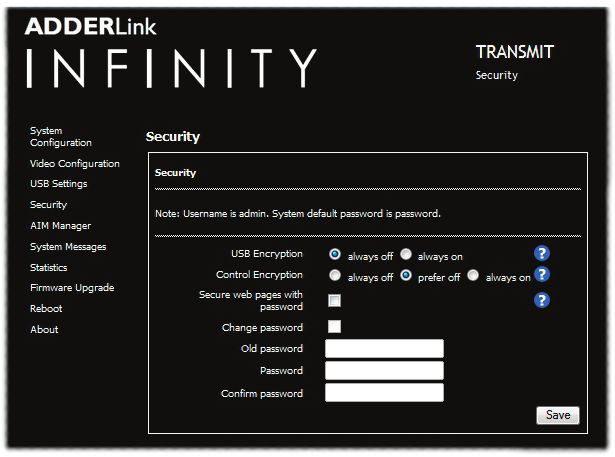
Contents
Introduction                                                                                                                 Configuration

                                                                                                                                                                                                                                                            INSTALLATION
 Welcome.................................................................................................................2    Initial configuration.............................................................................................19
 ALIF features..........................................................................................................3         Manual factory reset.....................................................................................19
 Firmware version 3.3 (or greater)....................................................................4                           AdderLink Infinity browser-based configuration utility........................20
 AdderLink Infinity (1002) unit features............................................................5                         Performing an upgrade.......................................................................................21
 AdderLink Infinity dual unit features................................................................6                       Options switches.................................................................................................21
 Supplied items - ALIF 1002.................................................................................7
                                                                                                                             Operation

                                                                                                                                                                                                                                                            CONFIGURATION
 Supplied items - ALIF dual...................................................................................8
 Optional extras......................................................................................................9       Front panel indicators........................................................................................22

Installation                                                                                                                 Further information
 Connections.........................................................................................................10       Getting assistance...............................................................................................23
 Mounting...............................................................................................................10    Appendix A - Transmitter (TX) unit configuration pages...........................24
                                                                                                                              Appendix B - Receiver (RX) unit configuration pages................................31

                                                                                                                                                                                                                                                            OPERATION
   TX video link..................................................................................................11
   TX audio links................................................................................................12           Appendix C - Tips for success when networking ALIF units.....................39
   TX USB link....................................................................................................12          Appendix D - Troubleshooting.........................................................................41
   TX AUX (serial) port...................................................................................13                  Appendix E - Glossary.......................................................................................43
   TX power in...................................................................................................13           Appendix F - Cable pinouts, video modes and general specifications....46
   TX/RX high speed links...............................................................................14                    Appendix G - Fiber modules and cables........................................................47

                                                                                                                                                                                                                                                          INFORMATION
                                                                                                                              Appendix H - Mounting options......................................................................48

                                                                                                                                                                                                                                                             FURTHER
   TX/RX Management port...........................................................................15
   RX video display............................................................................................16             Warranty...............................................................................................................51
   RX microphone & speakers........................................................................17                         Safety information...............................................................................................51
   RX USB devices.............................................................................................17              Radio frequency energy.....................................................................................52
   RX AUX (serial) port...................................................................................18
   RX power in...................................................................................................18
                                                                                                                             Index

                                                                                                                                                                                                                                                            INDEX
                                                                                                                                                                                                                                                            1
Introduction
WELCOME
Thank you for choosing the AdderLink Infinity (aka ALIF) family of high capacity digital One-to-one configuration
INSTALLATION
extenders/switches. By encoding high quality DVI video, digital audio and USB data into The simplest configuration links one RX unit to a single TX unit, either by a direct link or over much
greater distances via a high speed network. In both cases, Gigabit cable linking and/or fiber can be used.
Internet Protocol (IP) messages, ALIF units offer flexible ways to link peripherals and When both are deployed, connection speeds of up to 2 Gigabits are possible.
systems via standard networks.
This guide covers the ALIF 1002 and ALIF dual (2002T, 2000R and 2020) models, all
of which can transfer single link DVI video, digital audio and USB signals across your
network. The ALIF dual 2002T, 2000R and 2020 models can also handle a second single
link DVI video stream; while 2002T and 2000R models can additionally transfer one very
CONFIGURATION
high resolution Dual Link DVI video connection (or two single link DVI streams). The
capabilities are summarized below:
One-to-many configuration
Model ALIF ALIF dual ALIF dual ALIF dual VNC Using multicast techniques, an unlimited number
of receivers* can receive video and audio data
1002 T/R 2020 T/R 2002T / 2000R 2112T streams from a single TX unit.
Primary video Single link Single link Dual link Dual link
Secondary video x Single link Single link Single link
VNC support x x x Yes
OPERATION
Note:The ALIF dual VNC (2112T) unit is covered by a separate user guide.
ALIF 1002 and all ALIF dual variants both provide a choice of link connections. Each
supports both copper-based Gigabit Ethernet cabling as well as Fiber Channel over * A maximum of thirteen concurrent USB inputs (via
Ethernet (FCoE). These can be used in parallel to provide up to 2 Gigabit connection multiple RX units) are permitted to a single TX unit.
speeds with the added benefit of link redundancy that can maintain operation in the
event of a failed connection. Additionally, all ALIF dual models also benefit from a
INFORMATION
Management port that makes configuration even more straightforward.
FURTHER
ALIF units promote sharing; you can arrange for a limitless number of screens and
speakers, distributed anywhere across the network, to receive video and audio.You can ALIF and A.I.M.
also switch between any number of transmitter units using a single screen, keyboard and Where multiple ALIF units are used on a network, we have developed the AdderLink
mouse in order to monitor a potentially vast collection of remote systems. Infinity Management (A.I.M.) server to allow comprehensive and secure central
control of all transmitters, receivers and users.
Mixing ALIF dual units with the original ALIF 1000 series When using an A.I.M. server to configure ALIF
ALIF dual (2000 series) are complimentary to the original ALIF (1000 series) models units, it is vital that all ALIF units that you wish AdderLink
ADM USR UNC ETH1 ETH2 PWR
which do not support dual DVI channels or fiber optic linking. It is possible to mix ALIF to locate and control are set to their factory
INDEX
and ALIF dual transmitters and receivers on a network. However, whenever the two default settings. Otherwise they will not be MANAGEMENT SERVER
ADM USR UNC ETH1 ETH2 PWR
www.adder.com
types are cross connected, the extra abilities of the ALIF dual units will be temporarily located by the A.I.M. server. If necessary,
disabled. perform a factory reset on each ALIF unit.
The newer ALIF 1002 models now include the ability for a second Gigabit Ethernet or Please also see Appendix C - Tips for success when networking ALIF units
Fiber Channel over Ethernet connection as per the ALIF dual models. ALIF 1002 units
can be mixed with all ALIF dual units without any loss of functionality.
2ALIF FEATURES
AFZ lossless codec Transport Layer Security (TLS)
The AFZ compression scheme is primarily focused on improving the performance for ALIF 1002 and ALIF dual units support the industry standard Transport Layer Security
“natural” images (i.e. photographs and movies) and is automatically selected whenever (TLS) protocol. This offers protection against eavesdropping and tampering by third
there is a benefit to do so. The AFZ codec is lossless and is very low latency (a small parties when data are transferred between ALIF transmitters and receivers across
fraction of a frame delay). It generally achieves 50% improvement (in compression) over networks (and also between ALIF units and AIM servers).
INSTALLATION
the RLE scheme for any areas of the screen that consist of images, gradients, shadows
etc., elements commonly found in modern desktop environments.
To maintain compatibility with non AFZ -enabled transmitters and receivers there is an
automatic switching method which will revert back to RLE compression when an ALIF
(1000) receiver is connected to the newer ALIF 1002 series or ALIF dual (2000 series).
New feature: AFZ+ codec
CONFIGURATION
AFZ+ compliments the existing AFZ codec by providing greater compression for
increased speed where pixel perfect results are not the primary focus. The transmitter
video configuration page allows you to choose the required compression mode. Choices
are:
• ‘Pixel perfect’ - only uses pixel perfect AFZ,
• ‘Adaptive’ - guarantees frame rate, builds to pixel perfect,
• ‘AFZ only (pixel perfect),
• ‘Smoothest video’ - forces the maximum compression, or
• ‘AFZ+ Minimum compression’,
OPERATION
• ‘Advanced’ - allows you to choose the mode:
• ‘AFZ+ Middle compression’, or
• ‘AFZ+ Maximum compression’.
Magic Eye (anti-dither support added)
The Magic Eye feature increases performance and reduces network traffic when ALIF
units are used with Apple Macs and other host computers that have dithered video
output. It also improves performance if the video source is noisy (e.g. from a VGA-to-DVI
INFORMATION
converter).
FURTHER
Dithering is a technique used by some graphics cards to improve perceived image quality
by continuously varying the color of each pixel slightly. This gives the illusion of more
shades of color than the display can really reproduce, and smooths the appearance of
gradually shaded areas in images. Unfortunately dithering is an issue for KVM extenders
such as ALIF because it makes the image appear to be changing all the time even when
it is static, thus creating much more network data than can be carried by a Gigabit
Ethernet. The result is a reduction in video frame rate, which the user sees as slow
mouse response.
INDEX
Magic Eye works by ignoring small variations in the video from frame to frame. It is
enabled by default as it is not obvious to the user that his poor mouse behaviour is
caused by dithering. In most cases Magic Eye is invisible, but it can produce slight color
inaccuracies on the monitor. For full color accuracy, Magic Eye can be disabled (within the
transmitter video configuration page) for video sources which are not dithered or noisy.
3Teaming operation FIRMWARE VERSION 3.3 (or greater)
The units have dual network interface ports that can be used in parallel to produce
IMPORTANT: Please read this section completely before attempting
important benefits:
installation or upgrades.
• Improved connection speeds up to 2 Gigabits per second, and
• Important link redundancy that can maintain operation in the event of a failed The basic rule for A.I.M.-controlled installations is:
connection. If firmware version 3.3 (or greater) is to be used anywhere in an A.I.M.-controlled
INSTALLATION
AdderLink Infinity installation, then it must be used everywhere.
Teaming offers immediate speed improvements in a one-to-one arrangement...
For ALIF installations that do not use A.I.M. servers, it is possible to mix ALIF
firmware revisions, however, for best results you are recommended to upgrade all
ALIF units to v3.3 (or greater).
Important upgrade notes
• Always upgrade the A.I.M. server(s) to v3.3 (or greater) before attempting to upgrade
CONFIGURATION
...and also in multicast installations: (or add) AdderLink Infinity units at or above v3.3* – you will then be prompted to
upgrade the AdderLink Infinity units.
• ALIF1002 units are only available with firmware starting at v3.3 (and cannot be
downgraded), so if you add one or more ALIF1002 units to your installation, it is
mandatory to upgrade A.I.M. to v3.3 or greater (earlier A.I.M. firmware versions have
no knowledge of the new product).
• ALIF2020 units are only available with firmware starting at v3.4 (and cannot be
downgraded), so if you add one or more ALIF2020 units to your installation, it is
OPERATION
mandatory to upgrade A.I.M. to v3.3 or greater (earlier A.I.M. firmware versions have
no knowledge of the new product).
• If an AdderLink Infinity unit at v3.3 or greater is added, but you don’t want to upgrade
your A.I.M. server; simply upload the current firmware from your A.I.M. server to the
AdderLink Infinity unit in order to downgrade it. This is not possible on ALIF1002 and/or
ALIF2020 units.
INFORMATION
* If you add an AdderLink Infinity unit at or above v3.3 to an earlier version of A.I.M.
FURTHER
and then upgrade A.I.M. to v3.3 or greater, the AdderLink Infinity unit will not operate
after the upgrade.To rectify this, you will need to delete the record from the A.I.M.
database and factory reset the AdderLink Infinity unit before it will reacquire.
INDEX
4ADDERLINK INFINITY (1002) UNIT FEATURES
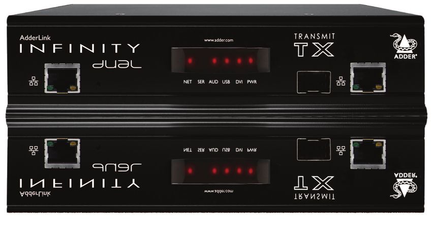
The ALIF 1002 units are housed within durable, metallic enclosures with most connectors situated at the rear panel -
the Ethernet ports are situated on the front panels. The smart front faces also feature the operation indicators.
ALIF 1002 transmitter - front ALIF 1002 receiver - front
INSTALLATION
CONFIGURATION
Teaming System Teaming System
port (Gigabit port (Gigabit
Ethernet) Ethernet)
Indicators port Indicators port
These six indicators clearly show the key aspects of operation: These six indicators clearly show the key aspects of operation:
• NET On when valid network link is present. • NET On when valid network link is present.
• SER On when the AUX (serial) port is enabled and active. • SER On when the AUX (serial) port is enabled and active.
• AUD On when audio is enabled and active. • AUD On when audio is enabled and active.
OPERATION
• USB On when the USB link with the connected PC is active. • USB On when USB is enabled and active.
• DVI On when a video input signal from the PC is detected. • DVI On when DVI video is enabled and active.
• PWR Power indicator. • PWR Power indicator.
ALIF 1002 transmitter - rear ALIF 1002 receiver - rear
INFORMATION
FURTHER
INDEX
Power USB Video Audio AUX Power USB Video Audio AUX
input port input line (serial) input ports output line (serial)
in/out port in/out port
Options Options
switches switches
(further details) (further details)
5ADDERLINK INFINITY DUAL UNIT FEATURES
The ALIF dual units are housed within durable, metallic enclosures with most connectors situated at the rear panel -
the Ethernet ports are situated on the front panels. The smart front faces also feature the operation indicators.
ALIF dual (2002 and 2020) transmitter - front ALIF dual (2000 and 2020) receiver - front
INSTALLATION
CONFIGURATION
Management 2020 version Teaming System Management 2020 version Teaming System
port only port (Gigabit port only port (Gigabit
Ethernet) Ethernet)
Indicators port Indicators port
These six indicators clearly show the key aspects of operation: These six indicators clearly show the key aspects of operation:
• NET On when valid network link is present. • NET On when valid network link is present.
• SER On when the AUX (serial) port is enabled and active. • SER On when the AUX (serial) port is enabled and active.
• AUD On when audio is enabled and active. • AUD On when audio is enabled and active.
OPERATION
• USB On when the USB link with the connected PC is active. • USB On when USB is enabled and active.
• DVI On when a video input signal from the PC is detected. • DVI On when DVI video is enabled and active.
• PWR Power indicator. • PWR Power indicator.
ALIF dual (2002 and 2020) transmitter - rear ALIF dual (2000 and 2020) receiver - rear
INFORMATION
FURTHER
INDOOR
USE ONLY OPTIONS DVI-D-1 DVI-D-2 DVI-D-2 DVI-D-1
AUX
1 2
ON
IN OUT
1 2
5V 2.5A COMPUTER 5V 4A
INDEX
Power USB Primary Secondary Audio AUX Power USB Secondary Primary Audio AUX
input port video video line (serial) input ports video video line (serial)
input input in/out port output output in/out port
Options Options
switches switches
(further details) (further details)
6SUPPLIED ITEMS - ALIF 1002
ALIF transmitter (1002T) package Power adapter
(20W) and
country-specific
power cord
INSTALLATION
Combined DVI-D and USB
cable (1.8m)
CONFIGURATION
ALIF1002T unit
OPERATION
Information wallet
containing:
Four self-adhesive rubber feet
Quick start guide Audio cable 2m
Safety document (3.5mm stereo jacks)
ALIF receiver (1002R) package
INFORMATION
FURTHER
Power adapter
(20W) and
country-specific
power cord
Information wallet
INDEX
containing:
ALIF1002R unit Four self-adhesive rubber feet
Quick start guide
Safety document
7SUPPLIED ITEMS - ALIF DUAL
ALIF dual transmitter (2002T/2020T) Power adapter
package (20W) and
country-specific
power cord
INSTALLATION
Combined DVI-D and USB
Single link DVI-D to DVI-D video cable cable (1.8m)
CONFIGURATION
ALIF2002T or
ALIF2020T unit
OPERATION
Information wallet
containing:
Four self-adhesive rubber feet
Quick start guide 2 x Audio cable 2m
Safety document (3.5mm stereo jacks)
ALIF dual receiver (2000R/2020R)
package
INFORMATION
FURTHER
Power adapter
(20W) and
country-specific
power cord
Information wallet
INDEX
containing:
ALIF2000R or Four self-adhesive rubber feet
ALIF2020R unit Quick start guide
Safety document
8OPTIONAL EXTRAS
INSTALLATION
Single mode fiber SFP module
Part number: SFP-SM-LC
Please refer to the table in Appendix F for
information about fiber modules and cables.
Single unit 19” rack-mount brackets plus four screws Single link DVI-D to DVI-D video cable
Part number: RMK4S Part number:VSCD1
CONFIGURATION
Combined dual link DVI-D and USB (USB type A to B) cable
Part numbers: VSCD3 (1.8m length)
Multi mode fiber SFP module VSCD4 (5m length)
Part number: SFP-MM-LC
OPERATION
Active copper SFP module
Part number: SFP-CATX-RJ45 Serial null modem cable 2m
Part number: CAB-9F/9F-NULL-MODEM
Double unit 19” rack-mount brackets plus ten screws
Part number: RMK4D USB cable 2m (type A to B)
Part number:VSC24
INFORMATION
FURTHER
Audio cable 2m
(3.5mm stereo jacks)
Part number: VSC22
20W power adapter
Part number: PSU-IEC-5VDC-4AMP
INDEX
Country-specific power cords
CAB-IEC-AUS (Australia)
VESA mount bracket plus four screws CAB-IEC-EURO (Central Europe)
Part number: RMK4V CAB-IEC-UK (United Kingdom)
CAB-IEC-USA (United States)
9Installation
CONNECTIONS MOUNTING
Installation involves linking the ALIF TX unit to various ports on the host computer, while Please see Appendix H for details about mounting options for the ALIF units.
INSTALLATION
the ALIF RX unit is attached to your peripherals:
CONFIGURATION
OPERATION
INFORMATION
FURTHER
Click a connection to see details
IMPORTANT: When using an AdderLink Infinity Management box to configure
ALIF units, it is vital that all ALIF units that you wish to locate and control are set
INDEX
to their factory default settings. Otherwise they will not be located by the A.I.M.
server. If necessary, perform a factory reset on each ALIF unit.
Please also see Appendix C - Tips for success when networking ALIF units
10TX video link
Standard ALIF (1002) units support one
Single Link video display at pixel clocks
up to 165MHz (equivalent to a maximum
resolution of 1920 x 1200 at 60Hz).
All ALIF dual units can simultaneously
INSTALLATION
support up to two Single Link high
resolution video displays at pixel
clocks up to 165MHz (1920 x 1200 at
60Hz maximum). ALIF2002 units can
alternatively support a single Dual Link very high Resolution video display at pixel
clocks up to 330MHz (equating to an example display mode of 2560 x 1600 at 60Hz).
CONFIGURATION
To make a video link
1 Wherever possible, ensure that power is disconnected from the ALIF and the host computer.
2 Connect your digital video link cable(s) to the DVI-D socket(s) on the TX unit rear panel:
ALIF (1002) ALIF dual ALIF dual
DV
I-D-1
OPERATION
DV
I-D-1 DV
I-D-2
To primary
video output CO
DV
I-
MP
port D-2 UT
ER
CO
MP
UT
ER
INFORMATION
FURTHER
To video
output To primary
port video output
port
Note:When using one very high resolution DVI-D dual link display To secondary
video output port
(not ALIF2020), use a DVI-D Dual Link cable (such as the supplied
Adder part:VSCD3) to connect the primary video port of the Note:When using two single link DVI-D displays, connect an
computer system to the DVI-D-1 connector of the ALIF dual. A dual additional video input from the secondary video port of the
link cable must also be used at the RX unit. computer system using the supplied secondary DVI-D link cable.
INDEX
3 Connect the plug at the other end of the cable(s) to the corresponding DVI-D video output socket(s) of the host computer.
11TX audio links TX USB link
ALIF (1002) and ALIF dual units support ALIF (1002) and ALIF dual units act as
two way stereo digital sound so that you USB 2.0 hubs and so can provide four
can use a remote microphone as well as sockets at the RX unit with only a single
speakers. connection at the TX unit.
INSTALLATION
To make audio links To make a USB link
1 Connect an audio link cable between the IN socket on the TX unit rear panel and 1 Connect the type B connector of the supplied USB cable to the USB port on the TX
the speaker output socket of the host computer. unit rear panel.
CONFIGURATION
DV
I-D-1 OP
TIO
NS
1
2
AU 1
X 2
OPERATION
IN
Speaker link from USB link from
host computer OU host computer
T
Microphone link
to host computer
INFORMATION
FURTHER
2 Connect the type A connector of the cable to a vacant USB socket on the
2 [Where a microphone is to be used]: Connect a second audio link cable between the
host computer.
OUT socket on the TX unit rear panel and the Line In socket of the host computer.
INDEX
12TX AUX (serial) port TX power in
The AUX port is an RS232 serial port Each ALIF unit is supplied with a power
that allows extension of RS232 signals up adapter and country-specific power cord.
to a baud rate of 115200. The port has When all other connections have been
software flow control, but no hardware made, connect and switch on the power
flow control. adapter unit.
INSTALLATION
To connect the AUX port To apply power in
1 Connect a suitable serial ‘null-modem’ cable (see Appendix F for pin-out) between a 1 Attach the output lead from the power adapter to the 5V socket on the rear panel of
vacant serial port on your computer and the AUX port on the right hand side of the the unit.
ALIF rear panel.
CONFIGURATION
IN
US DOO
EO R
NL
Y
OP
T
AU Note: Ensure that
X
Options switches 1
1
and 2 are both in the
5V
2.5 ‘OFF’ (up) position
1
OPERATION
A
to enable normal
Serial (null-modem) link Power cord operation of the unit.
from your computer from adapter See Options switches
for details.
INFORMATION
FURTHER
2 Connect the IEC connector of the supplied country-specific power cord to the socket
of the power adapter.
3 Connect the power cord to a nearby main supply socket.
Note: Both the unit and its power supply generate heat when in operation and will become
warm to the touch. Do not enclose them or place them in locations where air cannot circulate
to cool the equipment. Do not operate the equipment in ambient temperatures exceeding 40oC.
Do not place the products in contact with equipment whose surface temperature exceeds 40oC.
INDEX
13TX/RX high speed links
ALIF (1002) and ALIF dual units can be either connected directly to each other or via a
high speed network. The connections can be copper-based Gigabit Ethernet as well as
Fiber Channel over Ethernet (FCoE). These can be used in parallel to provide up to 2
Gigabit connections speeds.
A single System port (Gigabit Ethernet) is provided as standard on the right side of the
INSTALLATION
front panel. Additionally, the Teaming port, located just to the left, allows you to insert
either an optional Fiber Channel SFP module or Active Copper SFP module. The chosen
module can then allow either a fiber optic or additional Gigabit Ethernet link to be used
in parallel with the fixed System (Gigabit Ethernet) port.
Please see Appendix C for important tips about networking ALIF units.
To link ALIF dual units using the Teaming port
1 Insert the appropriate optional SFP module
CONFIGURATION
(SFP-MM-LC, SFP-SM-LC or To link ALIF units using the System port
SFP-CATX-RJ45) into the aperture on 1 Connect a CAT 5, 5e, 6, or 7 cable to the System port socket on the front panel of the
TR
the ALIF front panel: ALIF unit. AN
SM
IT
CAT 5, 5e, 6, or 7 link either
Optional Fiber Channel or directly from the other ALIF
Active Copper SFP module unit or from a Gigabit Ethernet
switch
OPERATION
2 Make your connection(s) between the chosen SFP module and either the other ALIF
unit or a suitable network switch:
Connect the transmit and receive
fiber optic links to the sockets on
the Fiber Channel SFP module.
INFORMATION
Then close the latch over the link 2 Connect the other end of the cable either to the other ALIF unit or to a Gigabit
FURTHER
connectors to lock them into place. Ethernet switch, as appropriate.
3 [For connections via a network] repeat steps 1 and 2 for the other ALIF unit.
Transmit and
receive fiber links
or Cable and fiber details
• For direct links over Ethernet cable, the length of cable should not exceed 100
metres (328 feet). Network cables used for connections may be category 5, 5e, 6 or
Connect a CAT 5, 5e, 6, or 7 cable 7 twisted-pair cable. ALIF TX units have an autosensing capability on their network
to the socket on the Active Copper
INDEX
interfaces, so for direct point-to-point connections, no ‘crossover’ Ethernet cable is
SFP module. required.
• For direct links via fiber, varying distances can be achieved depending on the module
and cable types used. Please refer to the table in Appendix G for detailed information.
The fiber links must have crossovers.
CAT 5, 5e, 6, or 7 link
14TX/RX Management port (ALIF dual units only)
The Management port on each ALIF dual unit provides a consistent method to gain
access to the internal configuration utility of each ALIF dual. Although the configuration
utility is accessible via the System (Gigabit Ethernet) port and also the Teaming port;
if the ALIF dual units are being used in a point-to-point arrangement, then it would
be necessary to temporarily reconnect each unit to a network in order to make
INSTALLATION
configuration changes. The Management port allows the admin user to simply connect
a computer directly to each ALIF dual unit and access the configuration utility using a
consistent IP address - thus negating the need to know the main port addresses of each
ALIF dual unit in advance.
To connect a computer to access the configuration utility
1 Connect a CAT 5, 5e, 6, or 7 link cable to the Management port socket located on the
far left side of the ALIF dual front panel. The port automatically configures itself, so no
CONFIGURATION
cross-over cable is required (but is supported if you do use one).
OPERATION
INFORMATION
FURTHER
2 Connect the other end of the link cable directly to the network port of your
computer.
3 Use a web browser to gain access to the internal configuration utility. The standard IP
address of the Management port is 192.168.1.42
Note:This standard IP address can be changed within the configuration utility.
INDEX
Please see the section AdderLink Infinity browser-based configuration utility for
further details.
15RX video display
Standard ALIF (1002) units support one
Single Link video display at pixel clocks
up to 165MHz (equivalent to a maximum
resolution of 1920 x 1200 at 60Hz).
All ALIF dual units can simultaneously
INSTALLATION
support up to two Single Link high
resolution video displays at pixel
clocks up to 165MHz (1920 x 1200 at
60Hz maximum). ALIF2000 units can
alternatively support a single Dual Link very high Resolution video display at pixel clocks
up to 330MHz (equating to an example display mode of 2560 x 1600 at 60Hz).
CONFIGURATION
To connect video displays
1 Connect the lead from the primary video display to the DVI-D-1 (DVI-D on ALIF 1002 models) socket on the RX unit rear panel:
ALIF (1002) ALIF dual ALIF dual
DV DV
I-D-2 I-D-2
OPERATION
DV DV
I-D-1 I-D-1
US US
VSCD3 cable ER ER
CO CO
to primary NS
OL
NS
OL
video display E E
INFORMATION
FURTHER
To video To
display secondary
video display
To primary
video display
Note:When using dual link on DVI-D-1 (not ALIF2020), the DVI-D-2
port will be disabled. If DVI-D-2 is already being used, then it must When using two single link DVI-D displays, connect an
be disconnected before dual link operation can occur on DVI-D-1. additional video cable to the DVI-D-2 port of the RX unit.
INDEX
2 (ALIF dual only) If required, connect the lead from the second video display to the DVI-D-2 socket on the RX unit rear panel.
16RX microphone & speakers RX USB devices
ALIF units can support a microphone as The ALIF RX unit has four USB ports
well as speakers providing the necessary to which peripherals may be connected.
connections have been made between The ports are interchangeable. To
the ALIF TX unit and the host computer. connect more than four peripherals, one
or more USB hubs may be used. The
INSTALLATION
total current that may be drawn from
the USB ports is 1.2A, which should
be sufficient for a keyboard, mouse (no
more than 100mA each) and any two
To connect a microphone (or line in) and/or speakers other devices (500mA maximum each). If
1 Connect the lead from a mono microphone to the 3.5mm socket labeled on the more power for USB devices is required, use a powered
rear panel. USB hub.
CONFIGURATION
2 Connect the lead from stereo speakers to the 3.5mm socket labeled on the rear To connect a USB device
panel. 1 Connect the lead from the device to any of the four LIN
E
MI I
USB sockets on the rear panel of the ALIF unit. CI
US
ER
CO
NS
1 OL
E
AU
X
OPERATION
Connection from USB device
Connection from
microphone or line in
from audio device
Supported USB Devices
The transmitter unit uses True Emulation technology to emulate the signals of certain
USB peripherals to the computer. This means that those peripherals appear to the
computer to be permanently connected, even when the receivers are switched
Link out to
INFORMATION
speakers elsewhere. This enables faster keyboard and mouse switching and allows for more than
FURTHER
13 identical USB devices. If the keyboards and mice are identical across the connected
3 Once the unit has been fully connected and powered on, access the RX System receivers, they are only enumerated once by the host. The following limitations apply:
Configuration page to check that the Audio Input Type setting matches the connection • Keyboards, mice and other HID devices are supported.
that you have made to the port: line, mic or mic boost (the latter provides +20dB gain). • Storage devices (i.e. flash drives, USB hard disks, CD-ROM drives) are supported, but
they may operate more slowly than with a direct connection.
• Isochronous devices (including microphones, speakers, webcams and TV receivers) are
not currently supported.
INDEX
• Many other devices (such as printers, scanners, serial adapters and specialist USB
devices) will work, but due to the huge variety of devices available, successful
operation cannot be guaranteed.
• If a device cannot be made to work, please contact Adder technical support as a
special entry within the advanced configuration may solve it.
17RX AUX (serial) port RX power in
The AUX port is an RS232 serial port Each ALIF unit is supplied with an
that allows extension of RS232 signals up appropriate power adapter. When all
to a baud rate of 115200. The port has other connections have been made,
software flow control, but no hardware connect and switch on the power
flow control. adapter unit.
INSTALLATION
To connect the AUX port To apply power in
1 Connect a suitable serial ‘null-modem’ cable (see Appendix F for pin-out) between the 1 Attach the output lead from the power adapter to the 5V socket on the rear panel of
AUX port on the right hand side of the ALIF rear panel and your remote serial device. the unit.
CONFIGURATION
/
LIN
EO IN
UT US DOO
EO R
NL
Y
OP
AU T
X
Note: Ensure that
1
Serial (null-modem) link Options switches 1
OPERATION
5V
from your computer 2.5 and 2 are both in the
A 1
‘OFF’ (up) position
Power cord from to enable normal
power adapter operation of the unit.
See Options switches
for details.
INFORMATION
FURTHER
2 Connect the IEC connector of the supplied country-specific power cord to the socket
of the power adapter.
3 Connect the power cord to a nearby main supply socket.
Note: Both the unit and its power supply generate heat when in operation and will become
warm to the touch. Do not enclose them or place them in locations where air cannot circulate
to cool the equipment. Do not operate the equipment in ambient temperatures exceeding 40oC.
INDEX
Do not place the products in contact with equipment whose surface temperature exceeds 40oC.
18Configuration
INITIAL CONFIGURATION
ALIF units are designed to be as flexible as possible and this principle extends also to Manual factory reset
INSTALLATION
their configuration. A factory reset returns an ALIF TX or RX unit to its default configuration.You can
perform factory resets using the AdderLink Infinity browser-based configuration utility
Direct linking or by using this direct manual method.
Where ALIF transmitters and receivers are directly linked to each other, very little To perform a manual factory reset
configuration action is required, provided that they have their factory default settings in 1 Remove power from the ALIF unit.
place. If the standard settings have been changed in a previous installation, you merely
2 Use a narrow implement (e.g. a straightened-out paper clip) to press-and-hold the
need to perform a factory reset on each unit.
recessed reset button on the front panel. With the reset button still pressed, re-
CONFIGURATION
Networked linking apply power to the unit and then release the reset button.
Where ALIF units are connected via networked links, you can either configure them
individually, or configure them collectively using an A.I.M. server:
• Configuring networked ALIF units individually - You need to specify the Ad
der
Lin
network addresses of the ALIF units so that they can locate each other. This is done k
by running the AdderLink Infinity browser-based configuration utility on a computer
system linked to the same network as the ALIF units.
• Configuring ALIF units collectively - The AdderLink Infinity Management
OPERATION
(A.I.M.) server allows you to configure, control and coordinate any number of ALIF
transmitters and receivers from a single application.
IMPORTANT: When using A.I.M. to configure ALIF units, it is vital that all units that
you wish to locate and control are set to their factory default settings. Otherwise
they will not be located by the A.I.M. server. If necessary, perform a factory reset on
each ALIF unit.
INFORMATION
Use a straightened-out paper clip to press
FURTHER
the reset button while powering on the unit
Please also see Appendix C - Tips for success when networking ALIF units
After roughly eight seconds, when the factory reset has completed, five of the front
Note: Please read the important advice in the section Firmware version 3.3 (or greater) panel indicators will flash for a period of three seconds to indicate a successful reset
before attempting installation or upgrades. operation.
INDEX
19AdderLink Infinity browser-based configuration utility
The browser-based configuration utility within all TX and RX units requires a To access the browser-based configuration utility
network connection between the ALIF unit and a computer on the same network. 1 Temporarily connect the ALIF unit and your computer, as discussed left.
The configuration utility allows you to perform many important functions. Please see 2 Run a web browser on your computer and enter the IP address of the ALIF port that
Appendix A for TX unit details and Appendix B for RX unit details. you are using.
It is possible to gain access to the internal configuration utility via any of the ports The default settings are as follows:
INSTALLATION
located on the front panel of each ALIF dual unit. For temporary connections on ALIF
dual units, you are recommended to use the Management port. There is no Management TX units RX units
port on ALIF 1002 models, so use the System port instead. Management port 192.168.1.42 192.168.1.42 Û ALIF dual only
To connect a computer to access the configuration utility System port 169.254.1.33 169.254.1.32
1 Connect a CAT 5, 5e, 6, or 7 link cable to either the Management (ALIF dual only) or Teaming port 169.254.1.43 169.254.1.42
System port socket on the front panel. The port automatically configures itself, so no
cross-over cable is required (but is supported if you do use one). Note:Where the port addresses of a unit have been changed and are not known, providing it
CONFIGURATION
is appropriate to do so, perform a manual factory reset to restore the default addresses.
ALIF dual ALIF 1002 (or dual) The opening page of the ALIF configuration utility should be displayed:
OPERATION
Temporary
link from your Temporary link
computer to the from your computer
Management port to the System port
2 Connect the other end of the link cable directly to the network port of your
INFORMATION
FURTHER
computer.
Use the menu options to choose
the required configuration page
INDEX
You can find further information about the configuration pages for the TX and RX
units within separate appendices later in this guide:
• Appendix A - Transmitter (TX) unit configuration pages
• Appendix B - Reciever (RX) unit configuration pages
20PERFORMING AN UPGRADE OPTIONS SWITCHES
ALIF units are flash upgradeable using the method outlined here. However, for larger A pair of Options switches are located on the rear panel of every ALIF unit.
installations we recommend that you use the AdderLink Infinity Manager (A.I.M.)
to upgrade multiple ALIF units. When using the method below, the ALIF unit will be Switch 1 - firmware image select
upgraded in sequence. Each ALIF unit retains a backup firmware image which can be used in situations
IMPORTANT: Upgrades must be performed on both the transmitters and where the primary firmware becomes corrupted (most often through failed upgrade
INSTALLATION
the receivers at the same time. Mixed firmware operation is not supported. operations). Using the backup firmware will allow you to regain operation of the unit.
WARNING: During the upgrade process, ensure that power is not Option switch 1 OFF Normal operation using the main firmware
interrupted as this may leave the unit in an inoperable state. ON Operate using the backup firmware image
If the upgrade process is interrupted and fails, it may be necessary to switch to the
backup firmware image in order to regain operation. See right for details. Option switch 2 is reserved and must remain in the OFF (up) position for normal
operation.
CONFIGURATION
To upgrade a single unit via network link
1 Download the latest upgrade file from the Adder Technology website.
Note:There are separate upgrade files for TX and RX units.
2 Temporarily connect the ALIF unit and a computer via a network (see AdderLink
Infinity browser-based configuration utility section for details).
3 Run a web browser on your computer and enter the IP address of the ALIF unit to be
upgraded.
4 Click the Firmware Upgrade link. Within the Firmware Upgrade page, click the Choose
OPERATION
File button. In the subsequent file dialog, locate the downloaded upgrade file - check
that the file is correct for the unit being upgraded. The file contains main and backup
images, you can choose to upgrade either the Main or the Backup.
5 Click the Upgrade Now button. A progress bar will be displayed (however, if your
screen is connected to the unit being upgraded then video may be interrupted) and
the indicators on the front panel will flash while the upgrade is in progress.
6 The indicators should stop flashing in less than one minute, after which the unit will
INFORMATION
automatically reboot itself. The upgrade process is complete.
FURTHER
Finding the latest upgrade files
Firmware files for the ALIF units are available from the Technical Support >
Updates section of the Adder Technology website (www.adder.com).
Note: It is possible to downgrade the AdderLink Infinity firmware. After installing the
older firmware, perform a factory reset on each AdderLink Infinity in order to clear the
INDEX
configuration file.
Note: If you have an ALIF unit at v3.3 or higher, and you wish to downgrade its firmware
via A.I.M. v2.5 to v2.9 (so as to use it within an A.I.M. v2.5 system), this can only be done
via the copper interface and not the fiber interface.
Note: Please read the important advice in the section Firmware version 3.3 (or
greater) before attempting installation or upgrades.
21Operation
In operation, many ALIF installations require no intervention once configured. The TX and
RX units take care of all connection control behind the scenes so that you can continue
INSTALLATION
to work unhindered.
FRONT PANEL INDICATORS
The six front panel indicators on each unit provide a useful guide to operation:
CONFIGURATION
Indicators
These six indicators clearly show the key aspects of operation:
• NET On when valid network link is present.
OPERATION
• SER On when the AUX (serial) port is enabled and active.
• AUD On when audio is enabled and active.
• USB On when USB is enabled and active.
• DVI On when the DVI Video channel is enabled and active.
• PWR Power indicator.
INFORMATION
FURTHER
INDEX
22Further information
This chapter contains a variety of information, including the following: GETTING ASSISTANCE
• Getting assistance - see right If you are still experiencing problems after checking the information contained within this
INSTALLATION
• Appendix A - Transmitter (TX) unit configuration pages guide, then we provide a number of other solutions:
• Appendix B - Receiver (TX) unit configuration pages • Online solutions and updates – www.adder.com/support
• Appendix C - Tips for success when networking ALIF units Check the Support section of the adder.com website for the latest solutions and
• Appendix D - Troubleshooting firmware updates.
• Appendix E - Glossary • Adder Forum – forum.adder.com
• Appendix F - RS232 ‘null-modem’ cable, General specifications.
CONFIGURATION
Use our forum to access FAQs and discussions.
• Appendix G - Fiber modules and cables
• Technical support – www.adder.com/contact-support-form
• Appendix H - Mounting options
For technical support, use the contact form in the Support section of the
• Safety information
adder.com website - your regional office will then get in contact with you.
• Warranty
• Radio frequency energy statements
OPERATION
INFORMATION
FURTHER
INDEX
23APPENDIX A - Transmitter (TX) unit configuration pages
This section covers the browser-based configuration utility for the AdderLink Infinity TX
(transmitter) unit. The TX utility has ten pages, titled as follows:
• System Configuration • System Messages
• Video Configuration • Statistics
• USB Settings • Firmware Upgrade
INSTALLATION
• Security • Reboot
• AIM Manager • About
CONFIGURATION
OPERATION
INFORMATION
FURTHER
INDEX
24TX System Configuration Unit Name
Name details that you can alter to distinguish this unit from all others. The name entered here will be read by
A.I.M. units (if used) for administration purposes.
Unit Description
Allows you to optionally add a description of the unit, such as its location. Useful when many ALIF units are being used.
System port
This section determines the IP address, netmask and gateway details for the main Gigabit Ethernet port located
INSTALLATION
on the right side of the front panel. The default IP address is 169.254.1.33 which is the zero config IP address
that allows the unit to work immediately in point-to-point mode.You are recommended to change this to an
appropriate address in the private IP range 192.168.xxx.xxx
The default netmask is 255.255.0.0. If you change the IP address to the private range, you are recommended to
change this to 255.255.255.0 The default gateway address is 169.254.1.1
Management port (ALIF dual models only - not shown in screenshot left)
Determines whether the port on the left side of the front panel is enabled and which IP address details it should use.
The default IP address is 192.168.1.42.You are recommended to leave this address unchanged (or at least keep such
CONFIGURATION
addresses constant across all of your ALIF dual units) so that all visiting engineers will know which address to use.
Teaming port
Determines whether the SFP socket on the right side of the front panel is enabled and which IP address details
it should use. The default IP address is 169.254.1.43 which is the zero config IP address that allows the unit to
work immediately in point-to-point mode.You are recommended to change this to an appropriate address in
the private IP range 192.168.xxx.xxx The default netmask is 255.255.0.0. If you change the IP address to the
private range, you are recommended to change this to 255.255.255.0
The default gateway address is 169.254.1.1 Note: Before the Teaming port can be used for connection via a network,
you need to ensure that the System port has been configured away from its zero config IP address.
Enable options
OPERATION
These checkboxes allow you to determine which peripheral options will be used:Video, audio, USB and serial.
Serial port options
These allow you to match the serial configuration being used by the attached PC host.
Identify unit
When clicked, these buttons cause the front panel indicators to flash to assist with identifying the ALIF unit
within a rack.
• The Identify Unit (short) button flashes the indicators for five seconds.
INFORMATION
• The Identify Unit (long) button flashes the indicators for one hour but can be overridden by clicking the
FURTHER
Identify Unit (short) button.
Thumbnail
The Thumbnail shows snap shots of the video feeds that are connected and reports the video resolutions/color
depths that have been detected. Click the Refresh Thumbnail button to update.
Target Multicast Configuration
The items within this section are required if a multicast group is being arranged i.e. many receivers connected
to the one transmitter. For the video port(s) and/or audio channel, you need to enter the multicast IP
addresses. In each case, the first address relates to the System (Gigabit Ethernet) port and the second address
to the optional Teaming port.
INDEX
In previous revisions of firmware, the destination IP address for video was decided by the RX. If multiple RX
units requested the same video source then all had to provide the same multicast destination IP address. In
revision 3.3 and above, the TX now decides the destination IP address for video and automatically informs any
interested RX units. In a system with a mix of new and old units, both RX and TX units must be configured
with the same destination IP address for video.
Note: All multicast addresses for each service endpoint must be unique across the whole ALIF installation.
25TX Video Configuration Peak bandwidth limiter percentage
The TX unit will employ a ‘best effort’ strategy in sending video and other data over the IP network. This means
it will use as much of the available network bandwidth as necessary to achieve optimal data quality, although
typically the TX unit will use considerably less than the maximum available. In order to prevent the TX unit
from ‘hogging’ too much of the network capacity, you can reduce this setting to place a tighter limit on the
maximum bandwidth permissible to the TX unit. Range: 0 to 95%.
Note: All of the following controls are available separately for each video port:
INSTALLATION
Background Refresh
The TX unit sends portions of the video image only when they change. In order to give the best user
experience, the TX unit also sends the whole video image, at a lower frame rate, in the background. The
Background Refresh parameter controls the rate at which this background image is sent. The default value is
‘every 32 frames’, meaning that a full frame is sent in the background every 32 frames. Reducing this to ‘every
64 frames’ or more will reduce the amount of bandwidth that the TX unit consumes. On a high-traffic network
this parameter should be reduced in this way to improve overall system performance. Options: every 32 frames,
every 64 frames, every 128 frames, every 256 frames or disabled.
Enable Magic Eye
CONFIGURATION
This feature, enabled as standard, aims to reduce the effect of dithering - a technique used by some graphics
cards to improve the perceived quality and color depth of images by diffusing or altering the colour of pixels
between video frames. The Magic Eye feature increases the frame rate and eliminates unnecessary network
traffic by ignoring the color dithering where it occurs. If the video source is not noisy or dithered then you can
switch off Magic Eye to enable full colour accuracy.
Use Default DDC and Choose Default DDC
When the Use Default DDC option is unticked, AdderLink Infinity will use the EDID that is reported by the
monitor connected to the receiver unit. However, if you tick the Use Default DDC option, you can then select
from a range of preset video resolutions from the Choose Default DDC drop down box. Once selected, the TX
will report itself capable of only supporting this one video resolution. Please note that all of the listed video
OPERATION
resolutions are single link DVI with a maximum pixel clock of 165MHz and a 60Hz refresh rate.
Enable Hot Plug Detect...
When this option is ticked, every time the monitor is changed at the receiver unit, a hot plug detect message
will be sent to the graphics card of the PC attached to the TX unit.
Period of Hot Plug Detect signal
This is the length of time that a hot-plug detect signal is applied. The default of 100mS is sufficient for the
majority of graphics cards, however, a small minority may need to be given a longer a period.
INFORMATION
Frame skipping percentage
FURTHER
Frame Skipping involves ‘missing out’ video frames between those captured by the TX unit. For video sources
that update only infrequently or for those that update very frequently but where high fidelity is not required,
frame skipping is a good strategy for reducing the overall bandwidth consumed by the system. Range: 0 to 100%.
Compression
Determines the (AFZ and AFZ+) compression method used for video transmission. Choices are:
• ‘Pixel perfect’ - only uses pixel perfect AFZ,
• ‘AFZ only (pixel perfect),
• ‘Adaptive’ - guarantees frame rate, builds to pixel perfect,
• ‘AFZ+ Minimum compression’,
• ‘Smoothest video’ - forces the maximum compression, or
• ‘AFZ+ Middle compression’, or
INDEX
• ‘Advanced’ - allows you to choose a fixed compression mode:
• ‘AFZ+ Maximum compression’.
To get here
1 Connect your computer to a port on the front panel.
2 Run a web browser and enter the IP address of the Management (ALIF dual only) or System port used:
http://192.168.1.42 (management port) or http://169.254.1.33 (system port)
If the address is unknown, perform a manual factory reset.
Note: ALIF dual screenshot shown above. ALIF 1002 models will provide options for a single video port. 3 If necessary, click the Video Configuration link. 26TX USB Settings
Enable Dummy Boot Keyboard
When ticked, the TX unit reports a virtual dummy boot keyboard to the attached PC to ensure that a
keyboard is always reported when the PC boots up. The dummy boot keyboard uses one of the 13 USB
endpoints, therefore if all 13 endpoints are required elsewhere for USB devices (or a KVM switch only supports
two HID devices) then it can be disabled by deselecting this option. See also Reserved Port Range below.
Disable Hi-Speed
INSTALLATION
This option allows you to force the system to run at the low/full USB speed of 12Mb/s, thus forcing USB 2.0 Hi-
Speed devices to adapt to the lower rate.
Hub Size
Using this option you can select whether the transmitter should report itself as a 13 or a 7 port USB hub.
Some USB hosts are only able to support 7 port USB hubs. If this option is set to 7, then only 7 USB devices
are supported by the PC.
Reserved Port Range
For some devices, e.g. touch screens, you may wish to ensure that they are always reported to the same USB
CONFIGURATION
port number so that the USB driver will always find the device. This option allows you reserve up to 8 ports
for certain devices. At the RX unit, the devices are assigned to the reserved ports. If a port reservation is to be
applied, then the dummy boot keyboard should be disabled. The default value for this option is ‘0’, i.e. disabled.
See Port Reservation on RX unit for further details.
TX Security
OPERATION
USB Encryption
This setting determines whether encryption should be applied to the USB data passed across the link. Note
that video data is never encrypted.
Control Encryption
This setting determines whether encryption should be applied to the control data passed across the link. Note
that video data is never encrypted.
Secure Web pages with password
When ticked, this option enables https security so that the configuration pages are only accessible to the admin
INFORMATION
user with a password.
FURTHER
Change/confirm password
These options allow you to change the admin password for the system.
To get here
1 Connect your computer to a port on the front panel.
2 Run a web browser and enter the IP address of the Management (ALIF dual only) or System port used:
INDEX
http://192.168.1.42 (management port) or http://169.254.1.33 (system port)
If the address is unknown, perform a manual factory reset.
3 Click either the USB Settings or Security links, as appropriate.
27TX AIM Manager
Enable AIM Control
Click this button to allow an A.I.M. (Adder Infinity Manager) box to take control of this TX. When the button is
clicked, the TX unit will be rebooted to allow the A.I.M. box to discover and control it.
INSTALLATION
CONFIGURATION
TX System Messages
Enable system messages
OPERATION
Tick to allow the creation of status and error messages by the unit.
Send system messages to remote Log Server
Choose this option to send the system messages to a remote server via the network. Provide the IP address of
a suitable server here also.
AdderLink Infinity servers use the User Datagram Protocol (UDP) for all Syslog traffic.
Store system messages in unit
When ticked, this option will store system messages within the memory of the unit. Click the View messages
INFORMATION
button to view the list or the Clear messages button to delete the list.
FURTHER
Update Now
Click to save and implement any changes that you make.
To get here
1 Connect your computer to a port on the front panel.
2 Run a web browser and enter the IP address of the Management (ALIF dual only) or System port used:
http://192.168.1.42 (management port) or http://169.254.1.33 (system port)
INDEX
If the address is unknown, perform a manual factory reset.
3 Click either the AIM Manager or System Messages links, as appropriate.
28You can also read