Wiring the Juan de Fuca Plate for Science: The NEPTUNE System
←
→
Page content transcription
If your browser does not render page correctly, please read the page content below

Wiring the Juan de Fuca Plate for Science:
                               The NEPTUNE System

                                               BRUCE M. HOWE
                  Applied Physics Laboratory, University of Washington, Seattle, WA 98105, USA

                                                HAROLD KIRKHAM
             Jet Propulsion Laboratory, California Institute of Technology, Pasadena, CA 91109, USA

                                   ALAN D. CHAVE AND ANDREW R. MAFFEI
                       Woods Hole Oceanographic Institution, Woods Hole, MA 02543, USA

                                                 SÉVERIN GAUDET
          Herzberg Institute of Astrophysics, National Research Council, Victoria, BC V9E 2E7, Canada

                                                    ABSTRACT
     NEPTUNE will “wire” the Juan de Fuca Plate in the northeast Pacific Ocean. It will enable in-depth study
     of life in extreme environments, plate tectonics, oceanography, and fisheries, to name but a few of the many
     topics. This will be accomplished by means of a multi-node submarine fiber-optic/power cable network de-
     ployed around the plate. It will provide power for the instrumentation as well as make seafloor sensors and
     interactive experiments easily accessible via the Internet to researchers, educators, and the public around the
     globe.
     The NEPTUNE Project is beginning its development phase. The many and varied issues associated with the
     infrastructure technical design are discussed, including power, communications, and data management and
     archiving.

                                                               developing observatories that can provide considerably
1.       Introduction                                          more power and real-time two-way communications.
                                                               Power consumption is inherently high for applications
The ocean sciences are on the threshold of a revolution        that require propulsion, pumping, lighting, heating or
that will fundamentally change the means by which many         cooling, and acoustics. Video and acoustics require high
processes in and beneath the oceans are observed. His-         data rates. Two-way communications are necessary for
torically, ship-based expeditions have characterized the       interactive experiments. Further, accurate timing is
oceans using data collected onboard and with short-term        necessary for navigation and tomographic imaging. For
deployments of autonomous instruments. It has become           some new technologies, the availability of substantial
increasingly apparent that many problems cannot be             power and communications capability on the seafloor will
addressed by time-limited visits alone. Ocean research is      reduce the development costs and time required to trans-
moving towards a mode of operation in which ship-based         fer long-term sensors from the laboratory to the oceans.
studies will be complemented by long-term observations         The Ocean Studies Board report notes that the “projected
from a network of coastal, regional, and global seafloor       power requirements for cabled observatories are antici-
observatories.                                                 pated to be 2-20 kW per node” and “The communications
A recent Ocean Studies Board report concluded that             requirement … depends primarily on the use of video
“Seafloor observatories present a promising, and in some       transmission and is anticipated to be, at most, less than 1
cases essential, new approach for advancing basic re-          Gb/s per node” (NRC, 2000).
search in the oceans.” It recommended that “NSF should         The NEPTUNE1 project will deploy a fiber-optic/power
move forward with the planning and implementation of a         cable network around and across the Juan de Fuca Plate
seafloor observatory program” (NRC, 2000).                     off the west coast of the North America to study a variety
Although many oceanographers are accustomed to de-             of geological, oceanographic, and ecological processes.
signing autonomous instruments with power consumption
limited to less than a watt, there are good reasons for        1
                                                                   http://www.neptune.washington.edu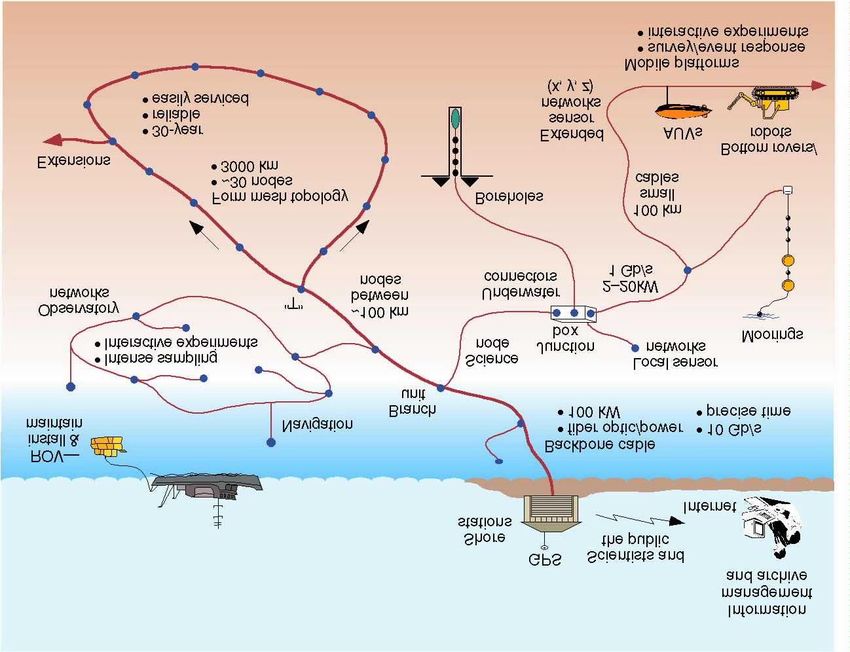
Figure 1. NEPTUNE will provide power and communications via fiber-optic/power cables to junction boxes (nodes) on
the Juan de Fuca Plate and surrounding areas. By connecting sensor networks to the nodes, with extensions onshore
and offshore into the interior, scientists will, for the first time, have the capability to study a host of interrelated processes
with high spatial and temporal resolution over long periods of time. Large amounts of reliable power and high-bandwidth
communications will be crucial elements of any such system.

NEPTUNE anticipates participating in the regional,                  (NEPTUNE Phase 1 Partners, 2000)2. The feasibility
tectonic-plate-scale component of the Ocean Observato-              study demonstrates that there are no insurmountable
ries Initiative, a new NSF program to support long-term             technical obstacles and identifies a path for realizing
research observations and interactive experiments from              NEPTUNE.
the sea surface to the seafloor and beneath. These arrays
                                                                    The feasibility study preparation included meetings of
will allow the coherent study of the behavior of the earth
                                                                    small ad hoc science working groups convened to explore
and ocean on time scales from seconds to decades and
                                                                    the scientific opportunities provided by NEPTUNE and
longer. (Delaney et al., 2000)
                                                                    to provide input to the design of the system. The science
It is envisioned that the NEPTUNE backbone will com-                working group topics were:
prise 3000 km of cable connecting about 30 evenly
                                                                    •    cross-margin particulate fluxes,
distributed nodes (Figure 1). Secondary branch cables
                                                                    •    seismology and geodynamics,
will extend to any location on the plate. At each node, a
junction box will provide standard power and Internet               •    seafloor hydrogeology and biogeochemistry,
communication interfaces for scientific sensors, sensor             •    ridge-crest processes,
networks, and various mobile platforms (Figure 2). The              •    subduction zone processes (fluid venting and gas
complete network will carry ~10 gigabits per second of                   hydrates),
data and deliver up to 100 kW of power with an opera-               •    deep-sea ecology,
tional life span of at least 30 years. NEPTUNE will                 •    water column processes, and
support large community experiments, smaller experi-                •    fisheries and marine mammals3.
ments developed by individual investigators, and a range            These topics indicate the breadth of science that will be
of innovative educational and outreach activities. The              addressed by NEPTUNE. The NEPTUNE infrastructure
latter are especially important for educating and involving
the public in the scientific research, whether in a major
                                                                    2
aquarium or a schoolhouse.                                            Available on the NEPTUNE web site,
A conceptual design and feasibility study was completed             http://www.neptune.washington.edu
                                                                    3
in mid-2000 as part of NEPTUNE’s Phase 1 effort                       White papers from each science working group are
                                                                    available on the NEPTUNE web site.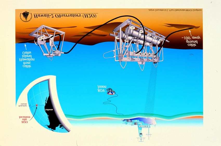
Figure 2. The essential elements of NEPTUNE. Land-based scientists and the public are linked in real time and interac-
tively with sensors, sensor networks, and various mobile platforms, in, on, and above the seafloor. NEPTUNE’s fiber-
optic/power cable and associated technology provide the enabling network infrastructure.

will positively impact the way the international and         and data management and archiving, are discussed in
national scientific communities conduct research.            more detail (Sections 6-8). Section 9 addresses systems
                                                             issues, such as interactions between subsystems and trade
NEPTUNE has now entered a period of detailed devel-
                                                             studies that are necessary. Section 10 contains concluding
opment (Phase 2) that will lead to installation (Phase 3)
                                                             remarks.
and operations (Phase 4) as early as 2005. The Phase 2
partners are the Institute for Pacific Ocean Science and
Technology (IPOST/Canada4), the California Institute of      2.       System Overview
Technology Jet Propulsion Laboratory (JPL), the Mon-
terey Bay Research Aquarium Institute (MBARI), the           The components and subsystems of NEPTUNE are
University of Washington (UW), and the Woods Hole            shown in schematic form in Figures 3 and 4. The four
Oceanographic Institution (WHOI).                            subsystems power, communications, timing, and control,
                                                             thread their way through the physical system, connecting
This paper describes our present view of the NEPTUNE         the scientists and other users on shore to science instru-
infrastructure, a system that will provide substantial       ments from the sea surface to the seafloor and beneath.
amounts of reliable electrical power and communications      (Here, we will group timing and control with communi-
capability to support existing and future science needs.     cations.). We have chosen a mesh topology for both
This technology development will play a crucial role in      power and communications to meet the capacity require-
enabling the fundamental paradigm shift necessary for        ments and to maximize reliability and flexibility.
observatory science.
                                                             A parallel power system as on land will be used. It uses
The balance of the paper is organized as follows. Section    a conventional submarine cable. Unlike typical undersea
2 gives an overview of the system followed by a descrip-     telecommunications systems, however, the current is not
tion of the major components: shore stations, cable, and     held constant. The power system is based on the use of
nodes (Sections 3-5). Then each of the subsystems we are     flexible, regulated power supplies, automatically adjust-
addressing in this paper, namely power, communications,      ing to changing load conditions. A multi-layered protec-
                                                             tion system will make the power system as fault-tolerant
4
                                                             as possible.
    http://www.neptunecanada.com
Sensors
Sensor Networks
Scientists
and other users
Data Manage J-Boxes
Power Cables
Shore Facilities Connectors
Control
Comms Timing Ops & Maint
Permits
Mapping
Installation
Cable routes
Figure 3. The major operational subsystems and the supporting components of NEPTUNE link the scientist/user to the
sensors and data.
For communications, NEPTUNE will use data network- catalog generation, data storage, data processing pipelines
ing technology that is widely used to connect the Internet and numerous other components.
to laboratories, classrooms, and homes around the world.
The major components of the physical system are the
From the dual perspectives of flexibility that preserves
shore station, the cable, and the nodes. After discussing
simplicity and cost minimization, the Ethernet family is
the functions of each of these components, we will ad-
the most promising technology. NEPTUNE is similar to
dress the subsystems.
campus networks that use this approach and, with multi-
ple shore connections, can benefit substantially from its
automatic routing and restoration capabilities. Network 3. Shore Stations
security will also be an important aspect of NEPTUNE’s
final desgin. The functions of the shore stations are as follows:
A well-integrated data management and archiving system • Provide stable, controlled power to the system cable,
is important to the scientific and educational goals of the • Provide two-way communication between the sensors
project, given the nature of the data produced by and the scientists,
NEPTUNE: • Provide accurate timing signals for the system,
• Provide the data management and archiving service,
• The wide variety and number of instruments, and
• Heterogeneous data, • Control and manage the overall system.
• The multi-disciplinary science goals,
• The projected terabytes-per-day data volume, As shown in Figure 1, it is assumed that there will be (at
• Long life span of the project. least) two shore stations, both to provide improved
system survivability as well as increased power and
Data entering the data management and archive system communications capability. The shore station in Victoria
must be properly time-stamped and packaged. At the is planned to be in the downtown area as part of a water-
other end, the system must allow the research and public front science center. The shore station in Nedonna Beach,
education communities to easily access relevant archive Oregon, is somewhat remote. It is likely that there will be
data. In-between lies management of the data flow, “network operations centers” in convenient locations, andBACKBONE BACKGONE
CABLE
BREAKOUT BREAKOUT SHORE FACILITY
LANDING
UNIT BBU2 UNIT BBU1
DATA
NETWORK NETWORK CENTER
MODULE NM2 MODDULE NM1
INSTRUMENT INSTRUMENT USER
MODULE IM2 MODULE IM1 INTERNET COMMUNITY
OPERATIONS
STAFF
FUTURE BACKBONE BACKBONE BACKBONE
CABLE
BREAKOUT BRANCH BREAKOUT SHORE FACILITY
EXPANSION UNIT BBUL MODULE BBM1 UNTIBBUN
LANDING
JUNCTION
BOX JB1 BACKBONE
INTERFACE BIN
SCIENCE
INTERFACE SIN NEPTUNE TOP LEVEL SYSTEM BLOCK DIAGRAM
BACKBONE
BREAKOUT
UNIT BBUM
NETWORK
MODULE NMM
NETWORK
MODULE NMM
Figure 4. System-level block diagram.
some of the above functions might be physically sepa- of nodes as well as sensor networks on the continental
rated from the shore station itself. shelf and slope will be challenging.)
The length of the cable network shown in Figure 1 is just
4. Cable over 3000 km. The cable will be the single most expen-
sive item, at about $10/m.
The function of the “backbone” cable is as follows:
• Transport power to the nodes, and 5. Nodes
• Transport data to and from the shore stations and the
nodes. The functions of the nodes are as follows:
Standard “commercial off-the-shelf” (COTS) cable from • Connect and branch the backbone cable,
the submarine telecommunications industry can be used, • Distribute stable low voltage power and perform load
with a single copper conductor (1 Ω/km), a 10-15 kV management, relaying, and protection,
rating, up to 30 optical fibers, and outside diameter under • Provide communications for the network backbone
25 mm. Because the cable has only a single conductor, and the sensors and sensor networks, and
sea water grounds at each node will be used. • Distribute timing signals.
In shallow or rough areas, the cable will have additional The junction boxes that form the node are configured
protection. It will be buried out to a water depth of about with underwater connectors that can be connected using
2000 m to protect it from fishing trawls. (The placement a remotely operated vehicle (ROV). The entire systemAn example of an in-service “node” is the Hawaii-2
Observatory (H2O) as shown in Figure 6. The junction
box has recently been attached to the out-of-service
Hawaii-2 analog telephone cable, half-way between
Hawaii and California (Butler et al., 2000; Chave et al.,
2000). The junction box is about 2 m long by 1 m wide
by 1 m high and is constructed entirely of titanium and
plastic for corrosion protection. It contains two pressure
cases to house the system electronics. An oil-filled mani-
fold is about 1 m off the seafloor and houses a set of wet-
mateable electrical connectors to which instruments may
be attached. The H2O junction box is designed to be
recoverable for servicing, and plugs into the telephone
cable at a termination frame. For NEPTUNE, the instru-
ment modules are expected to be similar to the H2O
design. The network mode will be permanently attached
to the spur cable, via a gimbaled cable termination.
6. Power
The basic trade-offs in the power system design can be
Figure 5. The conceptual layout of a NEPTUNE science node. made easily. Alternating current at 60 Hz can be ruled out
for the supply because of the effect of the cable capaci-
tance. Compensating this capacitance for the length scales
depends on these ROV-mateable connectors. Electrical of NEPTUNE would cost more than the cable itself
connectors for this purpose are proven. However, under- (NEPTUNE Phase 1 Partners, 2000). Low frequency
water-mateable optical connectors are an emerging alternating current (e.g., 0.1 Hz) is ruled out on the
technology, and are less attractive from both a cost and a grounds that it is more complex and costly than DC.
reliability perspective. Therefore, the power system should use DC for the
The configuration of the nodes and backbone cable will delivery function.
be such as to permit simple node recovery for mainte- The choice between a series system (as in conventional
nance and upgrade, using a research ship rather than a submarine telecommunications) and a parallel system (as
cable ship. Either a passive branch unit with a spur cable in terrestrial power systems) can be made on the basis of
to the junction box will be used, or the junction box will fault tolerance. Branching, and the provision of alternate
be in a loop of cable, long enough to reach the surface. circuits for power, is crucial to reliability. It has been
Such a configuration is crucial to keep maintenance costs estimated that the availability of the distribution part of
down. the terrestrial utility power delivery system would be
Figure 5 shows the layout of a science node using a single improved by a factor of between 5 and 10 if it were
spur cable. The backbone fiber-optic cable contains an in- interconnected, instead of radial (Billinton and Jonnaviti-
line, passive branching unit. The spur cable is 1.5 water hula, 1996: Brown and Taylor, 1999). Since the technol-
depths long and contains two conductors and twice as ogy to branch a series system does not exist, its
many optical fibers as the backbone cable. The network development and deployment would add greatly to the
module contains the high (~10 kV) voltage power supply system cost and complexity. Further, it can be shown that
and backbone router equipment, along with the low level a branched series network is not capable of delivering as
control system. It can be recoverable for maintenance or much power as a parallel network of the same topology;
upgrading using conventional research ships. a parallel system is always more efficient. Therefore, a
parallel system has been chosen.
The instrument module contains the low voltage power
supplies, low speed data switches, and instrument control The design approach is to maximize the amount of power
systems. It serves as the connection point for scientific that can be delivered to the science user, without a special
instruments. The instrument module can either be located cable. To provide less power than this amount would not
quite close to the network module or up to 100 km away, significantly reduce the cost; to provide more would
and more than one instrument module may be attached to increase costs greatly. For NEPTUNE, the system will be
a network module. able to deliver in aggregate about 100 kW to the distrib-Figure 6. The Hawaii-2 Observatory (H2O) seafloor observatory system midway between Hawaii and California.
uted nodes on the seafloor with high reliability. the discharge of the cable capacitance can be large and
sustained for several seconds. The approach routinely
While some parts of the proposed power system might be
taken to implement a DC breaker is to force a current
available commercially-off-the-shelf (for example, the
zero by means of stored energy.
cable), a good deal of the way the system works will have
to be tailored to the specific requirements of the Such a DC switch or breaker will be integrated with a
NEPTUNE system. Indeed, power systems with many of “smart” programmable controller that would accept local
the functional elements of NEPTUNE already exist measurements as well as remote commands. These “digi-
except that they operate at much higher voltages. tal relays” will constitute a primary building block of the
protection system and will be used, for instance, in
Rather than go into a detailed description of all the com-
branching units.
ponents, we highlight those that will require the most
attention. Protective Relaying
DC/DC Converter The purpose of the protection system is to isolate faults in
the power system, so as to ensure the safety of personnel
Within each node, the DC/DC converter must provide a
and equipment. For reliable operation, an essential part of
stable low voltage output, given an input voltage that is
this operation is to disconnect a faulted part of the sys-
varying considerably, up to 10-15 kV and 2-20 kW. The
tem, while not disconnecting any parts of the system that
converter will be a voltage-sourced switching design. The
are not faulted. In view of the difficulty (and expense) of
details of the design, such as the switching frequency and
performing repairs, such fault-tolerant operation is essen-
the implementation of the necessary low pass input and
tial. Breaking the system up into sections is therefore an
output filters will be determined as part of the design task.
essential part of maximizing reliability.
Because these units form the foundation of the overall
system, they will be highly reliable with redundancy built There are several ways that faults can be detected. The
in. simplest is based on the concept of overcurrent. A fuse
is an example of an overcurrent protection device. A
DC Switchgear
problem with this approach is that it does not distinguish
Because there are no naturally occurring current zeroes, faults that are close from faults that are remote. More than
direct current is non-trivial to interrupt. This will be a minimum amount of the system may thus be discon-
particularly true of the problem of interrupting faults in nected.
the NEPTUNE system, where the current available fromBy using information from several parts of the power for communications. While digital relaying is widely used
system, the protection scheme can do a better job of abroad, it is fairly new to the US, and relatively little US-
discrimination between faults. For example, a distance made COTS hardware is available.
relay gives better discrimination. In this device, a com-
Maximum Power
putation based on the measurement of both voltage and
current is used to estimate the fault’s location relative to While the voltage and current limits can be set simply by
the point of measurement. An even better protection consideration of insulation lifetime and perhaps voltage
scheme is the differential scheme. In this approach, the drop, establishing a value for the maximum power that
current at one end of a protected section is compared with can be delivered by a network is more complex. Although
the current at the other end. If there is a difference, there undersea cables tend to be DC, the theory of maximum
must be a fault between the two points of measurement. power has been addressed extensively only for AC net-
This kind of protection relies on the existence of a fairly works.
fast communication connection between the two ends. In As the point of maximum power transfer is approache,
NEPTUNE, this connection certainly exists so that a voltage stability manifests itself.. The symptoms of the
differential protection scheme can be implemented by approach of this kind of instability are a greater decrease
interfacing with the communication system. In the pro- in voltage than would be expected for a given increase in
tection plan proposed here, an Internet-based differential load. At the same time, the voltages around the system are
relaying scheme will be the first line of defense. hard to maintain. The problem is to determine the actual
For finding a fault location in a cable, a method that value of the maximum power transfer, bearing in mind
measures the relative arrival times of pulses of voltage or that in the general case the load will not be the same at all
current from the fault can be used. This method relies on the nodes, nor will it be time-invariant.
the availability of accurate time at both ends of the cable, Being careful to avoid this point of instability, steady-
which will be true for NEPTUNE (a fraction of a micro- state power flow calculations have been done to deter-
second). Time-of-flight relaying will therefore be used as mine the maximum theoretical power that can be deliv-
a second layer of protection. ered to the planned 30-node system shown in Figure 1.
In practice, because a fault might prevent direct com- For a cable resistance of 1 Ω/km and shore voltage of
munications, it would be prudent to adopt the utility 10 kV, a maximum of 6.7 kW can be delivered equally to
practice of having several layers of protection, some of all the nodes. If the cable resistance is 0.7 Ω/km and the
which can operate without communications. NEPTUNE’s shore voltage is 15 kV (corresponding to a recently
protection system will include differential, timing, dis- introduced long-haul COTS cable), the maximum power
tance, and overcurrent relaying. This way, the first (and to each node is 21 kW. In practice, all nodes will not have
best) lines of defense would be the differential scheme equal loads, and one would operate at less than the theo-
and the timing scheme; if the fault causes loss of commu- retical maximum.
nication, the distance relaying would operate; if the Dynamic Stability
distance relaying failed, the overcurrent system could
save the day. Since the loads are expected to be far more A DC/DC converter that includes a regulator presents
deterministic than those of a typical utility, overcurrent essentially a constant load to the source, since all load is
protection levels can be set quite close to the normal load on the regulated side of the converter. If the input voltage
values. These various levels of protection can be imple- drops, the converter compensates and the input current
mented using the digital relays mentioned before. increases. This means that the source will see a negative
incremental resistance, and the system may go unstable.
The task of designing and implementing the protection
scheme is the largest within the power system design. Since the negative incremental resistance effect is a low-
Functionally, it is known from utility practice how to frequency one only (due to the regulation action), Mid-
implement such a multi-layered protection system. The dlebrook (1977) showed that any oscillations that oc-
fact that the parameters being measured are direct current curred were likely to be at the crossover frequency of the
(not alternating) will make practically no difference. The input filter, where the filter impedance increased. He
biggest difference comes about because the DC sources demonstrated that by choosing the filter components
(the shore station power supplies) and the system imped- properly, the potential instability could be eliminated.
ances provide a natural limit to any fault current magni- Further, the filter design was not dissipative in the steady-
tude, whereas on land, there is effectively no limit on state.
current and ultra-fast fault clearing is needed. One study has already been done to demonstrate the
However, the design will be new in that it is based on stability of the system when subject to load fluctuations.
digital technology, and the first layer will use the Internet A Pspice simulation of a simple three-node system wasperformed. The three nodes were separated by 150 km, • NEPTUNE should choose a technology which meets
with the first one 500 km from the shore station (cable the requirements but not more.
resistance 1.5 Ω/km). The load at each node was adjusted • The communications technology must be available in
to 13.2 kW (96% of the 13.9 kW theoretical maximum a form factor and at a power consumption which is
for this system). Figure 7 shows the results of one simu- compatible with seafloor packaging.
lation with loads turning on and off at random. The
Based on these and other considerations, Gigabit Ether-
response is clearly a stable, overdamped response.
net (GbE) will be used to interconnect the NEPTUNE
nodes. Ethernet is the most widely used data networking
technology. GbE routing and switching hardware is
readily available from many vendors. Standard converters
(lasers and receivers) are also available with the ability to
drive 100 km or more of single mode optical fiber. GbE
hardware can serve as data concentrator/router/switch and
a repeater, eliminating the need for separate optical
amplifiers. Long haul 1 Gb/s full duplex communications
uses a pair of optical fibers. Higher data rates are feasible
using multiple fiber pairs; the NEPTUNE goal of a 10
Gb/s backbone can be met by ten pairs of fibers. Each
NEPTUNE node will contain a pair of gigabit switch
routers for redundancy.
A higher rate version of GbE (10 Gb/s) will be commer-
Figure 7. Results of a Pspice simulation with 3 nodes. See text cially produced in 2001, and will be evaluated when
for explanation. available. 10 GbE will have the same functionality as
GbE, including range capability of 100 km on single
mode fiber. The use of 10 GbE, and possibily some form
One of the crucial elements is the input filter to the of wavelength division multiplexing (WDM) could
DC/DC converters; if the filter is removed, the system substantially reduce the fiber count in the backbone cable,
quickly enters an unstable oscillatory mode and subse- with an attendant cost reduction.
quently crashes. This too has been simulated.
The science instrument interface on NEPTUNE will be
Note that this study demonstrates two aspects of the implemented using 10 and 100 Mb/s Ethernet as the
system behavior. First, it is unstable if the damping communications technology. A standard user interface is
components in the converter filter are omitted. Second, it being developed which will operate in a “plug and play“
is stable with a power transfer level as high as 96% of the mode, greatly simplifying the addition of new instrumen-
theoretical maximum. No unusual measures are required tation to the network. This interface definition will in-
for such a transfer. These issues are further discussed in clude the incorporation of data about the data, or
a recent paper (Howe, Kirkham and Vorpérian, 2000). metadata, into the data stream.
Monitoring and Control
7. Communications Monitoring and control of the NEPTUNE data network
can be implemented using the simple network monitoring
Backbone and Science Communications protocol (SNMP) served from network supervision work
stations located on shore. SNMP clients can also be
For NEPTUNE, there is no need to distinguish between
incorporated into the instrument module to simplify user
voice, video, and data as is common for a conventional
level supervision. These monitoring and control systems
telecommunication system. For this and other reasons, all
will function when the data communications backbone
NEPTUNE communication systems will use Internet
systems are operational.
Protocols (IP) that are now ubiquitous.
In addition, NEPTUNE will include a low level or out of
There are several standard communications technologies
band control system. This will provide full control of all
which might serve NEPTUNE, and selecting from them
router functions through a standard serial interface, and
has been guided by three principles:
can be used to configure the network and download
• NEPTUNE should use COTS components wherever software to the backbone routers. The low level control
possible to minimize development and acquisition system is fully redundant, and operates on a pair of
costs. dedicated optical fibers. The low level control system isbeing implemented using the serial ASCII interchange productivity and ensure that maximum value is extracted
loop (SAIL) protocol (ANSI/IEEE standard 997-1985) from the expensive-to-obtain data.
operating over a fiber optic physical link.
Data Acquisition
Time Distribution Protocols for packaging and transmitting data from
Accurate and precise time will be almost universally sensors to shore stations via lower-tier junction boxes and
necessary for science experiments. Standard IP protocols nodes will be specified as part of the basic infrastructure.
are available for clock synchronization (e.g., NTP), with Standard protocols will be used, but will have to be
a few milliseconds accuracy across the NEPTUNE net- documented. We will fully specify these protocols and all
work. interface requirements for experiment designers in
Phase 2.
For higher accuracy time requirements, GPS time infor-
mation with an accuracy goal of 1 µs will be distributed The issue of metadata is the foundation upon which a
using the low level control fibers. successful data management and archiving facility will be
built. Without it, data cannot be catalogued, which in turn
Network Modeling
means that it cannot be located and used effectively.
Efforts are currently underway at WHOI to use an ad- Metadata generation must be automated in a way com-
vanced network modeling package (OPNET) to build a patible with the standard sensor interfaces. The packaging
software model of the NEPTUNE network. When com- of sensor data must be designed such that the relevant
plete, this model will simulate network switches, routing metadata can be stored with the data. Again, the research
protocols, cable failures, instrument data transport of community must be consulted and choices made.
various types (seismic, video, chemical/biological sen-
In addition to allowing cataloguing of data sets, metadata
sors, etc.), time synchronization characteristics, band-
will be at the heart of the quality control and quality
width growth requirements, and a number of other
assurance plans. As the data flows through NEPTUNE
communications-related parameters.
systems, the quality of the metadata and the data itself
Work is currently being done to complete the model of a must meet pre-defined standards before archiving. This
seven-node laboratory test-bed version of the NEPTUNE will also allow problems in the data acquisition process to
network. This model draws components from a library of be flagged immediately.
models for existing COTS network components for both
Data Distribution
the NEPTUNE backbone and the science junction box
components. Cisco Systems is providing the hardware Phase 2 plans will draw on emerging technologies in
necessary to build the seven-node network represented by information management and on the experience of or-
the model. By using measurements made on the seven- ganizations such as NRC, NASA, NOAA and IRIS, all of
node network we will be able to validate the software which manage large and heavily used databases. Scien-
model and thus have confidence in the full NEPTUNE tific researchers are coming to expect user-friendly, web-
network design. based access to large data archives and NEPTUNE will
follow this course.
8. Data Management and There will be two major categories of data distribution
within NEPTUNE. The first is data streams that will
Archiving make raw data from the community experiments available
The NEPTUNE Data Management and Archive Facility to the full community of researchers and educators in near
will provide the scientific community with on-line access real time (subject only to network latency and the mini-
to all NEPTUNE scientific data to ensure full exploitation mal delays associated with automated quality control).
of those data. The Facility will be an integrated part of the Similar mechanisms will also exist for making proprietary
instrument planning, data acquisition, data processing, raw data from principal investigator (PI) experiments
and data distribution processes that occur with available in near real time to PIs and their teams. Both
NEPTUNE. Further, the Facility will guarantee that the these types of data stream may flow directly from the
valuable data sets obtained with NEPTUNE are preserved shore stations.
for use by future generations for research and education. The second is the query directed search in the archive
A well-designed and properly implemented Data Man- catalogues. These web-based solutions will be crucial to
agement and Archive Facility, as part of the capabilities successful implementation of a NEPTUNE archive, as
of NEPTUNE, will be a major contribution toward the they provide convenient access to data by all users, both
full exploitation of the unique characteristics of the new and established. In addition, the prevalence of open
NEPTUNE data. An effective archive will boost scientific standards in the web community allows significant lever-age to be obtained from standards developed for a large NEPTUNE archive will also contain links to publications
developer community, and significantly decreases the risk based on data from community and PI experiments or
of technological obsolescence of NEPTUNE implemen- from archival data.
tations. Increased emphasis on the web as an analysis as
Virtual observatories, a recent development in other
well as a data interchange environment will require that
disciplines5, would enrich the data exploration environ-
we consider metadata issues associated with the analysis
ment by providing links for querying across different data
of data as an integral part of any data management and
collections or for exploring related data stored at other
archiving approach.
sites in a uniform manner. The NEPTUNE archive will
Data Handling explore establishing links with other centres (e.g. IRIS,
Given that the current estimates of NEPTUNE data flow PODAAC)
are in the range of terabytes per day, the data handling
components of the system will be designed for volume 9. System Issues
and automation. There are several key areas that will be
examined in order to define these components. The The scenario published in the NEPTUNE Feasibility
system will require critical and robust criteria to deter- Report describes one of several possible designs and cost
mine which raw data are archived and whether processed models for the backbone, science instrumentation, and
data should be archived instead of raw data. Data com- other components of NEPTUNE (NEPTUNE Phase 1
pression in the form of lossy compression or sub- Partners, 2000). The subsequent work, some of which is
sampling algorithms will also be an issue and decisions described here, has focused on both clarifying some
on their use will come after consulting with the scientific aspects of the subsystems (e.g., the stability of the power
community. system) and system aspects. We are beginning the process
of analyzing the tradeoffs in the design. Throughout, we
An important component of the data handling is the are striving for the system architecture that best addresses
processing infrastructure. It is with this infrastructure that such factors as reliability, flexibility, operations, and
catalogue will be automatically built using sensor meta- maintenance. In the following we present a brief view of
data; that quality assurance will be automated to raise the work in progress, including some of the questions we
alarms in case of problems; that raw data will be reduced are facing.
for archiving (see above); that will allow archive users to
specify the type and degree of processing to be done for Network topology
their specific data requests; that will automate feature The exact network topology needs to be defined to maxi-
recognition or event detection in specific data streams. mize reliability, to remove single points of failure, and
Such an infrastructure is required since users are much maximize quality of service at all times including times
less interested in the actual raw data than in the data when partial failures occur. For example, how can we
products. If these can be generated with consideration for maximize the reliability of a spur, where a single failure
data quality and the application, then the scientific com- can compromise the rest of the system “downstream.”
munity will be better served.
Cable Engineering
Data Exploration
Cable vendors are being surveyed to identify the different
A design goal for NEPTUNE is to provide data sets that possible backbone trunk cables. Tradeoff studies on the
can be easily linked and visualized in both the time and number and types of fiber, amount and structure of cop-
space domains to address cutting-edge problems and to per, insulation and standoff requirements, ar-
allow completely new questions to be posed and an- mor/protection packages, and jointing, etc., are needed.
swered. Database design and “data mining” techniques A strategy for shelf/slope cables and nodes is also re-
are subjects of active research. NEPTUNE will take full quired.
advantage of existing databases while remaining flexible
enough to take advantage of new development. To ensure Nodes
that the NEPTUNE catalogues meet the scientific goals, A tradeoff study will be done to determine the optimal
mechanisms will allow users to incorporate their number of connecting ports on the network module and
NEPTUNE results and products (with sufficient quality the instrument module, as well as the optimal voltages
control) into the archive. Automated data processing and data rates. Putting COTS components in underwater
pipelines applying community standard algorithms in a
systematic and homogeneous fashion over the whole 5
White Paper: A National Virtual Observatory for Data
collection of NEPTUNE data will create derived-data
Exploration and Discovery,
products and catalogues for user querying. The
http://www.srl.caltech.edu/nvo/nvo7.0.pdfpressure cases requires careful consideration in regards to In the area of topology, studies will be conducted to
thermal issues and reliability. How do mean-time- determine (a) the cost of processing, compressing and
between-failure times quoted by industry for equipment buffering capabilities in the instrument/node versus the
normally used on land apply to this situation? bandwidth and reliability of the link to the shore station;
(b) the cost of data storage, raw data processing, cata-
Connectors
logue creation, quality assurance, buffering capability and
Tradeoff studies of optical versus electrical connectors staffing at the shore station versus high bandwidth and
indicate that the former are prohibitively expensive, reliability of the link to the archive centers.
though reliability issues are not as severe as expected (but
connector life cycle is limited to 100 matings). A valida- Integration and Testing
tion/test program for connectors carrying 100/1000BaseT The integration of the various subsystems and compo-
has been initiated. nents into one complete system is essential. Even though
individual and integrated components and subsystems
Power
will be thoroughly tested on land, a wet testbed that
A tradeoff study will be necessary to determine whether exercises the total system is a crucial element in the
the protection system should be based on digitally con- development.
trolled breakers or on switches. The former could work
under full system voltage, while the latter, which might A testbed is being planned for NEPTUNE in Monterey
entail fewer subsea components, would necessitate the Bay. This will be crucial to NEPTUNE. In the short term,
system first to shut down and then restart. it will be used to test the overall integration of the infra-
structure. In the longer term, it will be used for testing
Further, cost versus power capability tradeoff studies are new sensors and instrumentation before they are deployed
being conducted. on NEPTUNE. Further, a Victoria Experimental Network
Communications UnderSea (VENUS) is being planned which will provide
additional opportunities of this kind. The development of
A conceptual/functional baseline for the low-level con- these facilities will be coordinated with the overall
trol/timing system is being developed. Tradeoff studies of NEPTUNE effort.
1 and 10 Gb/s Ethernet are ongoing (the latter being an
emerging technology), and this has been expanded to
incorporate expected coarse WDM products. 10. Concluding Remarks
The modeling of the communications system is on going. As with any similar development effort at this stage, there
Once the seven-node model is validated the software are unresolved issues, some which we have described
components and associated assumptions will be used to here. Some, if not most, revolve around optimizing a
populate the larger NEPTUNE model. As the project particular system aspect given several good options to
progresses we will continue to use both the seven node chose from. All the work done since the Feasibility Study
model and the larger model to simulate the actual opera- reinforces the conclusions: NEPTUNE is technically
tions of the NEPTUNE network in more and more detail. feasible at a reasonable cost.
These models will help greatly in the design of the back-
NEPTUNE’s effectiveness is increased by a power
bone and science nodes for NEPTUNE.
system that can deliver high power levels, with the flexi-
We expect the data management and the communications bility to grow, and the required protection elements to
aspects of the power subsystem can also be incorporated make it highly reliable. It will be able to deliver in aggre-
into the software model as the NEPTUNE project pro- gate about 100 kW to the distributed nodes on the sea-
gresses. floor with high reliability. Similarly, the communications
Data management and archiving system will be able to provide 10 Gb/s or more aggregate
data rate. The data management system will provide easy
The studies related to data management are broadly access to the data for all the users.
grouped into two areas – data and topology (what gets
done where). In the data area studies will be conducted to
(a) determine file formats and metadata issues for differ- Acknowledgments. The authors gratefully acknowledge
ent classes of sensors; (b) determine the classes of data funding from their respective home institutions as well as
which will be archived; and (c) estimate the initial data other sources: the National Ocean Partnership Program
rates and projected rates over the lifetime of the project (NOPP), the National Science Foundation (NSF), and the
in order to ensure that the communications and storage National Research Council, Canada.
infrastructure is capable of handling the data.REFERENCES earth sciences at the scale of a tectonic plate, Ocean-
Billinton, R., and S. Jonnavitihula, A Test System for ography, 13, 71-83, 2000.
Teaching Overall Power System Reliability Assess- Howe, B. M., H. Kirkham, and V. Vorpérian, Power
ment, IEEE Transactions on Power Systems, 11, 4, system considerations for undersea observatories:
1670-1676, 1996. The basic trade-offs, IEEE Oceanic Engineering,
Brown, R. E., and T. M. Taylor, Modeling the Impact of submitted, 2000.
Substations on Distribution Reliability, IEEE Trans- Middlebrook, R.D., Input Filter Considerations and
actions on Power Systems, 14, 1, 349-354, 1999. Application of Switching Regulators, Proceedings of
Butler, R., A. D. Chave, F. K. Duennebier, D. R. Yoer- the Power Electronic Specialist Conference, PESC
ger, R. Petitt, D. Harris, F. B. Wooding, A. D. Bo- 77 Record, 366–382, 1977.
wen, J. Bailey, J. Jolly, E. Hobart, J. A. Hildebrand, NEPTUNE Phase 1 Partners (University of Washington,
A. H. Dodeman, The Hawaii-2 Observatory (H2O), Woods Hole Oceanographic Institution, Jet Propul-
Trans. Am. Geophys. Union, 81, pp 157, 162-163, sion Laboratory, Pacific Marine Environmental
2000. Laboratory), Real-time, Long-term Ocean and Earth
Chave, A. D., F. K. Duennebier, R. Butler, R. A. Petitt, Studies at the Scale of a Tectonic Plate: NEPTUNE
Jr., F. B. Wooding, D. Harris, J. W. Bailey, E. Feasibility Study (prepared for the National Oceano-
Hobart, J. Jolly, A. D. Bowen, and D. R. Yoerger, graphic Partnership Program), University of Wash-
H2O: The Hawaii-2 Observatory, Elsevier series on ington, Seattle, 2000.
Developments in Marine Technology, submitted, National Research Council (NRC), Illuminating the
2000. Hidden Planet: The Future of Seafloor Observatory
Delaney, J. R., G. R. Heath, A. D. Chave, B. M. Howe, Science, National Academy Press, Washington D.C.,
and H. Kirkham, NEPTUNE: Real-time ocean and 2000.You can also read


