AUDI A4 01 - Technical Features
←
→
Page content transcription
If your browser does not render page correctly, please read the page content below
254
                                     254
                                                 Service.

                                                            AUDI A4´01 - Technical Features

                                                            Design and Function

                                                                          Self-study programme 254

All rights reserved, including the
right to make technical changes.
AUDI AG
Dept. I/VK-5
D-85045 Ingolstadt
Fax 0841/89-36367
040.2810.73.00
Technical status 10/00
Printed in Germany

                                                 For internal use only.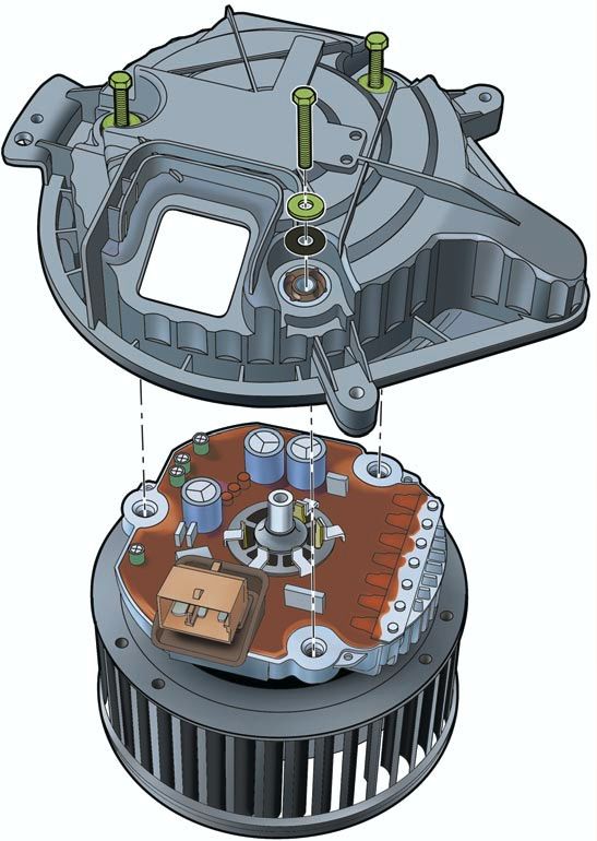
Advance by technology

          The new Audi A4,

          a vehicle which combines driving pleasure and good sense
          with the highest level of quality and sports styling.

                                               Control unit for vehicle electrical system...48

                                                      New engine programme ...18

                                                           Electronic stability programme with
                                                           brake assistance ...32

                                                         Steering column switch module ...44

                                                            Crash sensors for front airbag ...14

                                                         Multi-communication bar ...72

    Trapezium link
    rear axle...27

     Aero-floor ...7

2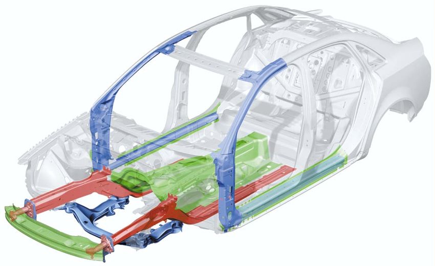
Contents

                                                                                              Page
Introduction . . . . . . . . . . . . . . . . . . . . . . . . . . . . . . . . . . . . . . . . . . 4

Body . . . . . . . . . . . . . . . . . . . . . . . . . . . . . . . . . . . . . . . . . . . . . . . . 8

Occupant protection . . . . . . . . . . . . . . . . . . . . . . . . . . . . . . . .                                            12

Engine and gearbox
2.0 l R4 and 3.0 l V6 engines (see SSP 255) . . . . . . . . . . . . . . . . . . . . . . . . . . . . . . . 18
Innovations - 2.5 l V6 TDI engine. . . . . . . . . . . . . . . . . . . . . . . . . . . . . . . . . . . . . . . . 19
Innovations - automatic gearbox . . . . . . . . . . . . . . . . . . . . . . . . . . . . . . . . . . . . . . . 23

Running gear
Axles    ............................................................                                                              26
Mechanical unit mountings . . . . . . . . . . . . . . . . . . . . . . . . . . . . . . . . . . . . . . . . . . .                    28
Brake system . . . . . . . . . . . . . . . . . . . . . . . . . . . . . . . . . . . . . . . . . . . . . . . . . . . . . . .         29
Brake assistance . . . . . . . . . . . . . . . . . . . . . . . . . . . . . . . . . . . . . . . . . . . . . . . . . . . .           32
Electrical system
Vehicle electrical system . . . . . . . . . . . . . . . . . . . . . . . . . . . . . . . . . . . . . . . . . . . . . . 36
CAN BUS system . . . . . . . . . . . . . . . . . . . . . . . . . . . . . . . . . . . . . . . . . . . . . . . . . . . . 38
Dash panel insert . . . . . . . . . . . . . . . . . . . . . . . . . . . . . . . . . . . . . . . . . . . . . . . . . . . . 40
Steering column switch module . . . . . . . . . . . . . . . . . . . . . . . . . . . . . . . . . . . . . . ..44
         Function circuit diagram . . . . . . . . . . . . . . . . . . . . . . . . . . . . . . . . . . . . . . . 46
Control unit for vehicle electrical system . . . . . . . . . . . . . . . . . . . . . . . . . . . . . . . . 48
          Function circuit diagram for "lowline" version . . . . . . . . . . . . . . . . . . . . . 50
          Function circuit diagram for "highline" version . . . . . . . . . . . . . . . . . . . . 52
Convenience system . . . . . . . . . . . . . . . . . . . . . . . . . . . . . . . . . . . . . . . . . . . . . . . . . 58
Anti-theft alarm system . . . . . . . . . . . . . . . . . . . . . . . . . . . . . . . . . . . . . . . . . . . . . . . 63
Radio - chorus II, concert II and symphony II . . . . . . . . . . . . . . . . . . . . . . . . . . . . . 65
Navigation IV and Navigation Plus-D . . . . . . . . . . . . . . . . . . . . . . . . . . . . . . . . . . . . 69
Multi-communication bar . . . . . . . . . . . . . . . . . . . . . . . . . . . . . . . . . . . . . . . . . . . . . 72
Electric logbook "Audi Logbook" . . . . . . . . . . . . . . . . . . . . . . . . . . . . . . . . . . . . . . . 74
Heater/AC
Design and function . . . . . . . . . . . . . . . . . . . . . . . . . . . . . . . . . . . . . . . . . . . . . . . . .              76
7-piston compressor . . . . . . . . . . . . . . . . . . . . . . . . . . . . . . . . . . . . . . . . . . . . . . . . .              77
Air conditioner . . . . . . . . . . . . . . . . . . . . . . . . . . . . . . . . . . . . . . . . . . . . . . . . . . . . . .        78
Glove compartment cooling . . . . . . . . . . . . . . . . . . . . . . . . . . . . . . . . . . . . . . . . . . .                    79
Solar roof . . . . . . . . . . . . . . . . . . . . . . . . . . . . . . . . . . . . . . . . . . . . . . . . . . . . . . . . . . .   80
Fresh air blower . . . . . . . . . . . . . . . . . . . . . . . . . . . . . . . . . . . . . . . . . . . . . . . . . . . . .         81
Actuators/sensors . . . . . . . . . . . . . . . . . . . . . . . . . . . . . . . . . . . . . . . . . . . . . . . . . . .            82
        Functional diagram for fully automatic air conditioner . . . . . . . . . . . . . .                                         84
Additional heater . . . . . . . . . . . . . . . . . . . . . . . . . . . . . . . . . . . . . . . . . . . . . . . . . . . .          86

                                                                                                                               Important:
                                                                                                           New
                                                                                                                               Note
The self-study programme will provide you with information on
design and functions.

It is not intended as a workshop manual.

For maintenance and repair operations it is essential that you
refer to the current technical literature.
                                                                                                                                            3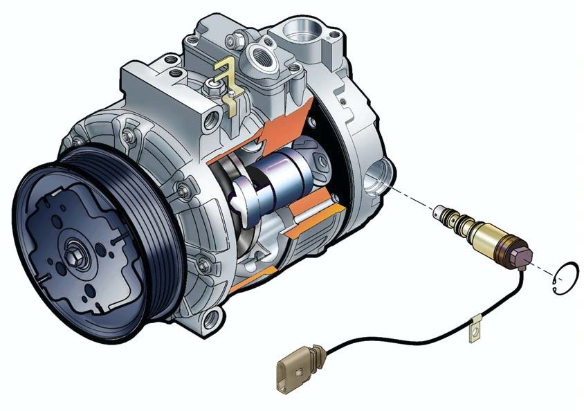
Introduction

    The architecture of motion

    Performance and smooth running

    The engine programme of the new Audi A4
    includes two petrol engines of a completely
    new design, with aluminium housings.
    The 2.0 litre 4-cylinder in-line engine with
    96 kW (130 PS) and the 3.0 litre V6 with
    162 kW (220 PS) fulfil the EU 4 emissions
    standard.
    A high degree of running smoothness is
    achieved via balancer shafts.

    Infinitely variable perfection

    For the first time in this vehicle class, Audi
    offers the infinitely variable "multitronic"
    automatic gearbox for all front-wheel drive
    versions.

                                                     The new light alloy running gear

                                                     With the four-link front axle, each wheel is
                                                     controlled by four aluminium transverse links.
                                                     The pivot bearings are also made from the
                                                     same light alloy.

                                                     The trapezium link rear axle for the quattro
                                                     drive system is also used in the front-wheel
                                                     drive models of the Audi A4.

4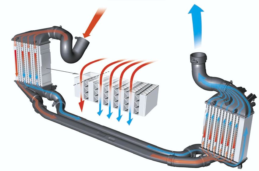
Finely-tuned aerodynamics

Despite the greater frontal area and the cool-
ing air current for the air conditioner (stand-
ard), it was possible to improve the CD value
by 5 %, in comparison to its predecessor,
to 0.28.

A special feature is the so-called aero-floor,
which provides for optimal airflow on the
underside of the vehicle.
                                                   High safety standards

                                                   With a thoroughly optimised body design and
                                                   comprehensive safety equipment, the new
                                                   Audi A4 is able to comply with all current valid
                                                   safety standards, throughout the world.
                                                   Crash sensors for the front airbags integrated
                                                   directly into the bumper bar, improve occu-
                                                   pant protection.

                                                   Communication centre on wheels

                                                   With regard to infotainment, the new
                                                   Audi A4 leaves nothing to be desired.
                                                   4 different audio systems, 2 differently config-
                                                   ured Navigation systems and a car phone
                                                   with voice operation are on offer.

                             SSP254_048

Electronic stability programme (ESP)
including brake assistant

For the latest ESP generation, the hydraulic
brake assistant is an integral part of the
standard equipment.
It is intended to assist the driver by automati-
cally increasing the brake pressure during
emergency braking.

                                                                                                      5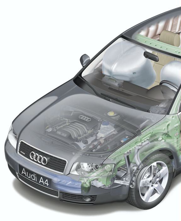
Introduction

    Vehicle dimensions of Audi A4´01

                               1628
                                                                         901

                                                                          106/110

                1528                                                    1526

                1766                                                    1937
                                         977

                                                                  951

                                                                                          471
                                               799                                445 L

                        1050                         870

                                                                                                       976
                                                             303
                                         257

          921                         2650                                                976

                                      4527
                                                                           1000
                                        1400

                                                           1357

                                                                                                1088

                                                                                                  SSP254_051

6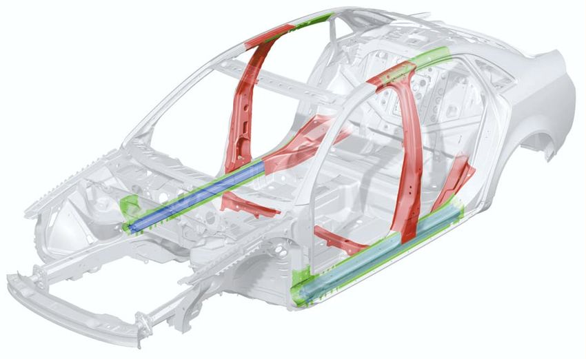
The aero-floor
not only contributes to improved aero-           The aero-floor was designed so as to guaran-
dynamics.                                        tee ground clearance and resistance to stone
It was also possible to reduce the noise level   impact and to prevent accumulation of dirt,
by approx. 3 dB (A).                             stones and snow.

   Front-wheel drive

   Four-wheel drive quattro and V6 engine
                                                                       SSP254_053

Part of the additional costs generated by the
aero-floor could be compensated by dispens-
ing with certain panelling components as                The engine compartment noise insu-
well as by dispensing with PVC protection of            lation does not form part of the aero-
the underside of the vehicle. The latter is of          floor.
advantage during recycling.

                                                                                                 7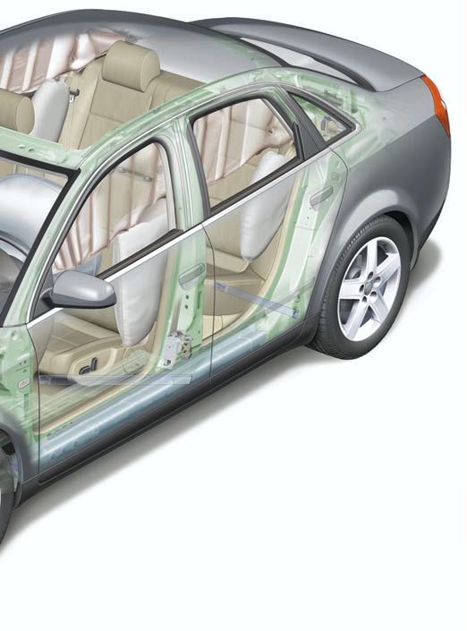
Body

                                                      Front impact design features

    The new Audi A4 is designed for optimal con-      – the straightened longitudinal member with
    formance with current crash requirements            crash-optimised octagonal cross-piece
    and safety standards.                             – the rigid and significantly wider bumper
    This could only be achieved by increasing the       cross-piece
    body weight.                                      – the integration of the member structures
                                                        into the passenger cell
    In order to reduce this additional weight to a    – strength, rigidity and weight-optimised
    minimum, the proportion of light-weight             suspension strut cross-piece
    materials has been increased in comparison
    to its predecessor.
    The proportion of high-strength sheet metal
    parts as well as the use of a total of 10 large
    component "tailored blanks", contribute sig-
    nificantly to weight reduction.
    Body rigidity has been increased by 45 % by
    increasing the number of connection points
    by 25 %.

                                                                                     SSP254_054

    Depending upon vehicle weight, performance and fuel consumption are the characteristics
    which our customers can experience at first hand.

8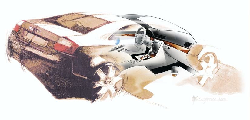
Side impact design features

In the floor area, the cell consists of three
large tailored blanks, which ensure a stable
connection between the front and rear of the
vehicle.

Weight-saving optimisation of deformation
characteristics in the event of a side impact
was achieved by the use of an aluminium
extruded profile in the sill.

    “tailored blanks” are made-to-measure
    sheet metal parts with varying material
    thickness.
                                                SSP254_055

                                                SSP254_056

                                                             9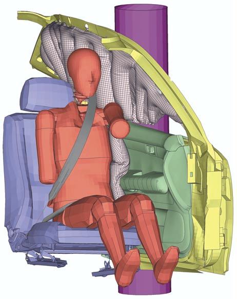
Body

     Doors

     The doors of the Audi A4 demonstrate a sig-
     nificantly increased rigidity due to the one-
     piece door shell construction.

     For the first time, a so-called spray-on noise
     insulation is used, which is sprayed on as
     required and allows weight reduction for the
     same effectiveness.

                                          Noise insulation

                                                                                                    SSP254_067

                                                             The newly developed sub-frame is bolted to
                                                             the door shell via fitted bolts.

                                SSP254_066

                                                                                        Roof
     In addition, the doors have been fitted with a
                                                                                           Roof trim strip
     second weatherseal. One weatherseal is fitted
     to the door and the other is fitted to the body.
                                                                                                Door window
     The new door concept permits a reduction in                                                seal
     the overall noise level of a further 3 dB (A) and
     thus contributes to improving the aero-acous-
     tics.

                                                                                                    Door window
                                                Door trim

                                                             Door seal            Door frame seal

                                                                         Door frame            SSP254_075
10
Emergency door locking
In the event of failure of the central locking,
e.g. due to power supply faults, each door can
be individually locked without using the lock
cylinder.
Firstly, with the door open, the cap must be
removed. Emergency locking is effected by
inserting the ignition key.
After the door has been closed, it is not possi-
ble to open it from the outside.
The door can be opened from the inside by
actuating the door release handle twice. SSP254_069
Luggage compartment lid
The luggage compartment lid should always
be operated via the radio remote control.
The lock cylinder for the luggage compart-
ment lid is integrated into the handle.
Continuous locking of luggage compartment SSP254_070
If the lock cylinder is in the horizontal posi-
tion with the key removed, the luggage com-
partment lid is no longer included in the
central locking system. Opening is then only
possible via the centre unlocking button of
the radio remote control.
When the lock cylinder is in the vertical posi-
tion, the lid is an integral part of the central
locking system.
SSP254_071
Manual unlocking and opening
is effected by turning the key to the left.
In this position, it is not possible to remove
the key, which must subsequently be returned
to the vertical position.
Thus, it is ensured that the luggage compart-
ment lid is an integral part of the central lock-
ing system.
SSP254_072
11Occupant protection
Overview of system
G 283 G 284
J162 K145
J220 AIRBAG
OFF
J285/K75
J533
AIRBAG E224
T16
AUS EIN
N95
N131
J393 J234 J526
N199 N200
G179 G180
N153 N154
N201 N202
N277 N278
G 256 G 257
SSP254_029
12To complement the comprehensive body The system comprises driver/passenger air-
modifications, occupant protection has been bags, front side airbags, optional rear side
improved through the further development of airbags, SIDEGUARDS®, three point front seat
the familiar 8.4 airbag system. belts with ball tensioners and belt force limit-
ers, three point rear outer seat belts, centre
lap belt (for fixed rear seat bench), Isofix pre-
paration in rear of vehicle, and a total of 6
non-central accelerometers:
– 2 front impact crash sensors
– 2 driver/passenger side airbag crash sen-
sors, (in the B-pillar for side impact)
The new generation bears the designa- – 2 driver/passenger rear side airbag crash
tion 8.4 E, where the E stands for sensors, (on the C-pillar for side impact)
"extended".
The position of the sensors is selected so that The external sensors deliver digitised acceler-
they are installed as near as possible to the ation data to the airbag control unit, which is
outer structure of the vehicle. then evaluated in the control unit and which
This enables quicker deceleration detection in triggers the relevant restraint system compo-
the event of an impact. nents.
Key
E224 Key switch for switching off K75 Airbag warning lamp
passenger’s side airbag K145 "Airbag off" warning lamp,
G179 Side airbag crash sensor, driver’s passenger's side
side (B-pillar) N95 Airbag igniter, driver's side
G180 Side airbag crash sensor, passenger’s N131 Airbag igniter 1, passenger's side
side (B-pillar) N153 Igniter for belt tensioner, driver's side
G256 Crash sensor for rear side airbag, N154 Igniter for belt tensioner,
driver’s side passenger's side
G257 Crash sensor for rear side airbag, N199 Igniter for side airbag, driver’s side
passenger's side N200 Igniter for side airbag, passenger's
G283 Front airbag crash sensor, driver’s side
side
G284 Front airbag crash sensor, N201 Igniter for rear side airbag,
passenger’s side driver’s side
J162 Heater control unit N202 Igniter for rear side airbag,
J220 Control unit for motronic passenger's side
J234 Airbag control unit N277 Igniter for airbag in B-pillar
J285 Control unit with display unit in (SIDEGUARD®), driver's side
dash panel insert N278 Igniter for airbag in B-pillar
J393 Central control unit for convenience (SIDEGUARD®), passenger's side
system T16 Connector, 16-pin, diagnosis
J526 Control unit for telephone / connection
telematics
J533 Diagnosis interface for data bus
(Gateway)
13Occupant protection
Crash sensors for front airbag G283, 284
Both sensors for front impact detection func- If a certain signal threshold is exceeded in the
tion in conjunction with the crash sensor and front airbag crash sensor, a threshold reduc-
the safe sensor which are integrated into the tion is activated in the airbag control unit,
airbag control unit J234. which results in a shorter triggering time.
Upper body
SSP254_058
Head
Triggering of belt tensioners
Triggering of front airbags
the steering column
Damping function
Front airbags inflated
Vehicle rebound
Belt force limiter
Deceleration load
response in
response
Impact
Time [ms] SSP254_063
14 SSP254_064Crash sensors for side airbags
G179, 180, 256, 257
In order to trigger the components of the
restraint system, two simultaneous impact
detection signals are required for the plausi-
bility check:
– from both opposing crash sensors
(B-pillar left with right and/or
(C-pillar left with right) and
– from the control unit internal crash sen-
sors.
The crash sensors are designed in such a way
that incorrect installation is excluded.
SSP254_059
Airbag control unit J234
The warning lamp for airbag K75 is activated Re-encoding of the airbag control unit is no
continuously following a detected impact. longer possible after the first crash data mes-
"CRASH DATA STORED" and the triggered sage is stored.
components are displayed with fault code
during fault memory readout. Triggering is performed in two thresholds
depending upon the deceleration value:
– Threshold 1 = belt tensioners only
– Threshold 2 = belt tensioners and airbag(s)
Sensors and components to be replaced
following an accident, are listed in the
current workshop manual.
1516
Occupant protection
Deactivation of passenger airbag
Deactivation of the passenger airbag is only
possible via the key switch. In the Audi A4, the
passenger's side airbag is also deactivated.
Deactivation via the diagnostic tester is not
possible.
If a customer requires the deactivation func-
tion where a key switch is not fitted, this can
only be achieved by retrofitting the key switch
and airbag OFF lamp and by re-encoding of
the airbag control unit.
Front belt attachment
Belt lock and strap fastenings are perma-
nently connected to the seat frame. Thus, in
conjunction with the seat belt height adjuster,
an optimal belt fitting can be achieved for
each seat position.
Front head restraints
In order to offer a high degree of occupant
protection in conjunction with the seat belt
and airbag, the front head restraints have
been supplemented by an integral locking
mechanism.
a
SSP254_101
SSP254_011
SSP254_102Crash signal processing
There are two separate crash signal outputs:
One crash signal is output via the conven-
tional wiring and triggers the following func-
tions:
– Transmitting an emergency call via the
control unit for telephone/telematics J526
(optional)
– unlocking the vehicle,
– Switch on interior light
(switch must be set to door contact),
– switching on hazard warning lights via the
central convenience electronics J393.
The auxiliary heater J162 (optional) is
switched off by the central convenience
electronics J393 via a CAN convenience
message.
The second crash signal output functions via
the convenience CAN bus, which switches off
the engine fuel supply via the engine control
unit J220.
17Engine and gearbox
Engine
The 4-cylinder, 2.0 l engine
provides high propulsive force due to the
maximum torque of 195 Nm at 3300 rpm.
Power output [kW]
Torque [Nm]
SSP254_038 Engine speed in rpm SSP254_060
The 3,0 l V6 engine
with five-valve cylinder head, produces162 kW
(220 PS) at 6300 rpm from 2976 cm3.
The maximum torque of 300 Nm is developed
at 3200 rpm.
Power output [kW]
Torque [Nm]
Engine speed in rpm SSP254_061
SSP254_030
Detailed information on these engines
can be found in SSP 255.
18Innovations 2.5 l V6 TDI engine
Power output [kW]
Torque [Nm]
SSP255_045 SSP255_039
Engine speed in rpm
Technical data
Capacity: 2496 cm3 Injection system: Bosch VE VP 44 S3.5
Bore: 78.3 mm Turbocharger: VNT 20
Stroke: 86.4 mm Exhaust emissions class: EU 3
Compression: 18.5 : 1 Consumption: urban 11.0 l/100 km
(6-gear, quattro) country 6.1 l/100 km
Power output: 132 kW (180 PS) average 7.8 l/100 km
Torque: 370 Nm at 1500 rpm
The main features of the basic engine are the The injection system was modified in order to
same as those of the familiar V6 TDI engine reduce exhaust gas and particle emissions.
with 132 kW (180 PS).
Power output and torque curve values could
be maintained under conditions which were
well within EU 3 limit values.
Limit value [%]
EU 3 limit values 100 %
Particle = 0.05 g/km
CO = 0.64 g/km
HC+NOx = 0.56 g/km
NOx = 0.50 g/km
NOx HC+NOx CO Particle
SSP255_038
19Engine and gearbox
Injection pump VP 44 S3.5
Forced flush
return
Distributor bushing
Distributor shaft
Solenoid valve
Supply piston
Thermal shoulder
Forced flush feed SSP255_040
The high pressure section of the injection In order to initiate pre-injection for cold and
pump has been redesigned with regard to warm engines, the solenoid valve dynamics
pressure levels and quicker solenoid valve have been significantly increased.
actuation. The associated increased heat generation in
the solenoid valve, is compensated by
The injection pressure at part throttle has improved fuel flow and optimal filling of the
been increased by the following measures: high pressure section is achieved.
– increased cam stroke from 3.5 to 4.0 mm Noise levels have been significantly improved
– more stable support structure for high by the pre-injection for cold and warm opera-
pressure section on pump body tion and the use of dual-spring nozzle hold-
– conversion from 3 pistons with a diameter ers.
of 6.0 mm, to 2 pistons with a diameter of
7.0 mm.
By reducing the number of high-pressure pis-
tons from 3 to 2, it was possible to reduce
high-pressure leakage via the sealing sur-
faces.
Previously, pre-injection via the solenoid
valve was only realised during the engine
warm-up phase.
20Injector
For the first time, an ICU injector (Inverse Cav- Due to the improved spray formation through
ity Undercut) is used, which has a dual needle the use of the ICU injector, it was possible to
guide. reduce the exhaust emissions and the particle
values by up to 20 %.
The advantage of this ICU geometry is a sig-
nificantly improved spray formation, espe-
cially in the part throttle range for small
injection quantities and short needle lift.
ICU seat geometry
SSP255_041
Dual needle guide
SSP255_042
ICU seat geometry Standard seat geometry
21Engine and gearbox
Charge air cooler
Through duct
Cooling duct section
SSP255_043
The existing series connection of the two The charge air cooler design comprises two
charge air coolers for the 110 kW engine is sections, in which part of the charge air is fed
inadequate for the 132 kW engine with its via a through duct, connected to a space-sav-
high air throughput. ing pipe, to the section of the other charge air
cooler which is fitted with cooling fins.
A new charge air cooler design was devel- The rest of the charge air is fed directly
oped, in order to ensure optimal charge air through the cooling fins, via a separate pipe,
flow. to the second charge air cooler and into the
through duct.
22Innovations - automatic
gearbox
5-speed 01V automatic gearbox
The Audi A4 quattro MJ01 with 5-speed auto-
matic gearbox features a new shift lever gate,
together with a new shifting concept.
The existing selector lever positions, 4,3,2 are
discontinued and are replaced by the "S"
position.
Gearshift positions 4,3,2 have been discontin-
ued as they are hardly ever used in practice. P
The DSP (dynamic shift programme) and "tip- R +
tronic" function have basically rendered them N
D
superfluous. S
With the selector lever is in the "S" position, a
sports shift programme provides the relevant
driving dynamics. In position "S", the DSP
also provides for adaptation of the driving set
values to the driving conditions.
The introduction of the "S" programme ena-
bles a significant extension of the useful shift
range between economy and sports.
The "S" programme comprises the following
special features: SSP254_117
– If, during driving with constant accelerator Example: Dynamics code 40
pedal position, the selector lever is set to Shift map 1
the "S" position, the system always shifts
down, within defined limits.
– In order to achieve a direct driving reaction
in response to accelerator pedal actuation,
Throttle valve angle [%]
the converter clutch is closed during driv-
ing operation, where possible.
– If, in conjunction with the overall gearbox
ratio, 5th gear is designed as overdrive
gear (overdrive, 4+E), only 1st -4th gears
are shifted.
We recommend the multi-function steering
wheel (available as optional extra) with steer-
ing wheel "tiptronic" ("thumb shifting").
Gearbox output speed [rpm]
D - normal driving programme SSP254_103
S - sports driving programme
23Engine and gearbox
"multitronic" and 5-speed automatic gearbox
SSP254_088
An innovation for all automatic gearboxes is Special feature:
the "Tip in D " function. This means that the
steering wheel "tiptronic" function is now The countdown from approx. 10 seconds to
also available in selector lever position "D". return to normal automatic operation is inter-
rupted, in the event that cornering is detected
The transition to the "tiptronic" function is or the vehicle is in overrun operation.
effected by actuating one of the two tip
switches on the multi-function steering wheel When normal driving conditions are detected
(selector lever in position "D"). The system again, the countdown recommences from
then switches to the "tiptronic" function for approx. 10 seconds.
approx. 10 seconds. All gears can be shifted
within the range of permissible engine
speeds.
The system returns to normal automatic oper-
ation approx. 10 seconds after the last tip
request.
24Notes
25Running gear
Axles
Four-link front axle
The thorough further development of the
light-weight construction resulted in a weight
reduction of approx. 8.5 kg at the front axle.
In addition to all transverse links, the pivot
bearing is now also made of aluminium.
The wheel bearing is attached to the pivot
bearing via four bolts. The wheel hub can be
pressed in and out.
Aluminium mounting bracket SSP254_087
Aluminium
spring plate
Shock absorber valves
Aluminium pivot bearing
SSP254_086
The suspension strut mounting is of the bulky
rubber bearing construction.
It consists of two functional components:
– The inner part forms the connection to the
piston rod.
– The larger outer part provides for acoustic
insulation of the shock absorber.
SSP254_085
26Trapezium link rear axle
The rear axle design with largely identical Apart from the axle mounting, the two axle
components is used in both the front-wheel versions differ only in the wheel carrier and
drive as well as in the quattro versions. the wheel bearings.
Camber
adjustment
SSP254_089
Toe adjustment
The front-wheel drive version is fitted with a
wheel bearing unit with integral wheel hub,
which is mounted on a stub axle forged
together with the wheel carrier.
SSP254_083
Camber
adjustment
SSP254_091
Toe adjustment
The wheel bearings of the quattro version
consist of pressed-in, double-row angular ball
bearings with conventional wheel hubs.
SSP254_082
27Running gear
Mechanical unit mountings
Engine mounting 1
Cross member
Gearbox
mounting 3
Torque
member
SSP254_107
Engine
mounting 2
A newly designed three-point mechanical unit The additional cross member enables support
mounting is used in the new Audi A4. over a longer lever arm, which positively influ-
ences vibration and load cycle characteristics.
The hydraulically damped engine mountings
(electrically-controlled version for diesel The aluminium cross member is bolted to the
engines) are fastened directly to the longitu- body as well as to the rear subframe mount-
dinal members via die-cast aluminium brack- ings and, in addition to its supporting func-
ets. tion for the gearbox mounting, serves as a
body-stiffening tunnel bridge.
The gearbox mounting is effected by means
of a conventional rubber bearing on a body-
mounted aluminium carrier, which is pro-
duced according to the hollow sand casting
technique.
The three-point mechanical unit mount-
ing is used for all engine/gearbox
combinations except those including
the 01V 5-speed automatic gearbox.
28Brake system
The new Bosch ESP 5.7 is introduced in the
Audi A4. The ESP 5.7 is distinguished by the
following special features:
– The hydraulic unit and control unit form a
single unit.
– The charging pump (actuation of ESP
hydraulic pump V156) is discontinued.
– A brake assistant is included.
Hydraulic modulator
Due to the increased brake fluid viscosity at
extremely low ambient temperatures, the
required delivery rate for the return pump for
ABS V39 could not be achieved without a
charging pump (resulting from the increased
suction resistance in the system).
The purpose of the development of the
ESP 5.7 was to improve the suction of the ABS
return pump so that the charging pump was
no longer necessary.
The charging pump could be discontinued
through the use of a two-stage ABS return
pump, enlarging the cross-section of the SSP254_094
brake lines and the use of a larger-dimen-
sioned central valve in the brake master cylin-
der.
29Running gear
Single-stage ABS return pump
Suction volumes
UT OT UT OT UT
Suction volumes
UT OT UT OT UT
SSP254_095
The graphic shows a comparison of the
suction volumes of both pump versions.
In the single-stage ABS return pump, the The suction pressure is correspondingly high
entire suction volume must be drawn in and and increases with increasing viscosity.
flow through the suction line during one Cavitation and the associated drop in
piston stroke (piston stroke from TDC to BDC). performance on the pressure side, are the
results.
30Two-stage ABS return pump
Working chamber 2
Suction volumes
Working chamber 1
UT OT UT OT
UT OT UT OT
SSP254_096
The piston of the two-stage ABS return pump As the entire suction volume is supplied
is stepped and has a double-acting function almost continuously, the maximum suction
within two working chambers. flow rate is significantly lower, which dimin-
ishes the suction pressure and prevents
Suction is effected in two stages; brake fluid cavitation.
being drawn through the suction line during Thus, a quick pressure build-up is ensured,
each piston stroke. even at extremely low temperatures.
Function:
If the piston moves from BDC to TDC, the In working chamber 1, brake fluid is now
brake fluid in working chamber 1 is com- drawn via the open inlet valve, out of the suc-
pressed whereas working chamber 2 is simul- tion line and out of the connection line to
taneously under suction. working chamber 2.
If the piston then moves from The suction flow rate in the suction line is
TDC to BDC, the brake fluid which has been diminished by that amount which flows back
drawn into working chamber 2 is forced back out of the connection line from working
into the suction line against the inlet valve. chamber 2
(drawn in during previous working operation).
31Running gear
Brake assistant
Investigations in accident research have During emergency braking, the brake assist-
shown, that the majority of drivers fail to ade- ant aids the driver by increasing the brake
quately actuate the brakes in an emergency pressure automatically, to a level exceeding
situation. the locking limit.
This results in insufficient brake pressure The ABS (Anti-lockbrakingsystem) is thus
being generated to achieve maximum vehicle quickly brought into the operating range,
deceleration. which enables a maximum vehicle decelera-
This lengthens the braking distance. tion to be achieved.
Brake servo pressure sensor G294 is used for
detection of emergency braking.
Pressure sensor G294
SSP254_093
Pressure [p]
For this purpose, the pressure increase gradi-
ent (pressure build-up with respect to time) is
evaluated and, if necessary, the brake assist-
ant is activated.
Time [t]
SSP254_092
Emergency braking
Normal braking distance
32The function of the brake assistant is
sub-divided into 2 phases:
• Phase 1 • Phase 2
If the pressure increase gradient exceeds a If the pressure determined by the driver falls
specified value (emergency braking), the ABS below a certain value after triggering of the
return pump and the relevant solenoid valve brake assistant, the system pressure is
are activated by the ESP control unit and the restored to the pedal pressure determined by
brake pressure is thus increased into the ABS the driver.
control range, in a similar manner to that of
the control system for an electronic differen-
tial lock.
Brake assistant activated Brake pedal unloaded Brake assistant
switches off
Phase 1 Phase 2
ABS control
Brake pressure [p]
range
Time [t] SSP254_084
Brake pressure determined by an
experienced driver
Regulated brake pressure The integral inlet and outlet valves in the
(brake assistant) hydraulic modulator are no longer sim-
ply switched on/off, but are regulated
Determined brake pressure via supplied voltage.
insufficient inexperienced driver This enables more precise control on
extremely slippery surfaces, e.g. ice.
33Running gear
Brake fluid reservoir
The brake fluid reservoir is secured with an
additional screw.
The new maintenance opening in the brake
fluid reservoir enables the extraction of brake
fluid from both brake fluid chambers.
The new brake filler and bleeder unit
VAS 5234 must be used for this purpose.
SSP254_098
Fastening screw
Maintenance opening
Brake light switch
The fastening and adjustment of the brake
light switch are new.
The brake light switch is secured to the pedal
bracket via a bayonet fitting.
The position of the push rod is adjusted for
the basic setting.
For this purpose, the brake light switch must
be released by turning it anti-clockwise.
The push rod catch is released simultane-
ously via the locking lug.
The push rod is now free and can be adjusted
without risk of damage.
The push rod is pulled out to the stop for the
basic setting. SSP254_099
The brake light switch can now be inserted
into the pedal bracket and secured by turning
clockwise. At the same time, the push rod
catch is locked automatically by means of the
locking lug.
34Notes
35Electrical system
Vehicle electrical system Control unit for headlamp
Chip card
reader R99
range control J431
Control unit for
telematics J499
Control unit for
mobile phone control
electronics J412
Battery
Control unit with
display in dash panel
insert J285
Front airbag crash
sensor, passen-
ger’s side G284
Control unit for
coolant fan, Control unit
Stage 1+2 J293 for ESP J104
Front airbag crash sen-
sor, driver’s side G283
Steering column
Control unit switch module J527
for Motronic J220
Control unit for auto-
matic gearbox J217
36Side airbag crash sensor,
passenger’s side G180 Door control units,
passenger side J387
rear right,
Side airbag crash sensor, rear
optional J389
driver’s side G256
passenger’s side G257
Control unit for trailer
recognition J345
Control unit for
parking aid J446
Control unit for
tyre pressure
monitor J502
Airbag control
unit J234
Central control unit for
convenience system J393
Side airbag crash sensor,
driver’s side G179
ESP sensor
SSP254_008
Door control unit,
driver’s side J386,
rear left, optional J388
Control unit for vehicle electri-
cal system J519
37Electrical system
CAN BUS networking
J285
Gate-
way
Diagnosis system
J507
J386 J387
J220
R99
J217 J388 J389
J499
J526
J104 J393
J502
TRACK
SEEK FR FF
EJECT
TUNE SCAN
CD CDC 1 2 3 4 5 6 AS
1 AM 2 TP
EJECT Audi symphony DOLBY SYSTEM
1 FM 2
BASS MIDDLE TREBLE BALANCE FADER RDS
PLAY SDE
TAPE RANDOM
J234 R
E87
J162
NOX sensor
(USA only)
J345 J446 J401
J527
J402
J519
G85 J136
J527
R94
+
-
R
T
J453
The ignition switch signals and the
control buttons for multifunction
and "tiptronic" steering wheel are
registered via the steering column
38 electronics.CAN data bus
The Audi A4 is equipped with a widely
extended CAN data bus system.
For communication between the
installed control units and the diagnos-
Due to the ever increasing number of control
tic tester, two diagnosis wires (K and L)
units installed in the vehicle and the associ-
are available.
ated requirement for data exchange, the
importance of the CAN data bus system
increases significantly.
G85 Steering angle sender J402 Control unit for operating electronics,
E87 Operating and display unit for navigation, TV tuner
air conditioner J446 Control unit for parking aid
J104 Control unit for ESP J453 Control unit for multi-function
J136 Control unit for seat adjustment with steering wheel
memory, optional J499 Control unit for telematics
J162 Auxiliary heater, optional J502 Control unit for tyre pressure monitor
J217 Control unit for automatic gearbox J507 Control unit for speech entry
J220 Control unit for motronic J519 Control unit for vehicle electrical
J234 Airbag control unit system
J285 Control unit with display unit in J526 Control unit for telephone -
dash panel insert permanent installation
J345 Control unit for trailer recognition J527 Control unit for steering column
J386 Door control unit, driver’s side electronics
J387 Door control unit, passenger side R Radio
J388 Rear left door control unit, optional R94 Interface for navigation
J389 Rear right door control unit, optional R99 Chip card reader
J393 Central control unit for convenience
Drive BUS 500 kBaud
system
Convenience BUS 100 kBaud
J401 Navigation system control unit Display BUS 100 kBaud
Diagnosis connection
K wire
Diagnosis connection
L wire (2nd K wire)
The newly developed adapter VAS 6017 ena-
bles communication with all control units.
SSP254_112
39Electrical system
Dash panel insert
Cruise control system ON
SSP254_012
Auto-check system
Setting buttons for digital clock, Call-up button for Reset button for trip
date and instrument illumination service interval recorder
indicator
There are two dash panel insert versions: The dash panel insert of the new Audi A4 is
equipped with
– "lowline"
– "highline" – the gateway for linking the three data bus
systems: drive, convenience, information
The "highline" version is equipped with a – and the immobiliser III.
high-quality colour display for the driver infor-
mation system and is installed in vehicles
with navigation systems as well as telematics.
40User prompt in the centre display via the con-
trol switch in the centre console, is only avail-
able in vehicles with
– navigation system ("highline" version only)
and/or
– telematics and/or
– auxiliary heater and/or
– tyre pressure monitoring.
The optional driver information system
includes the following functions:
– radio clock
– auto-check system SSP254_104
– on-board computer.
The km range is indicated in the basic ver-
sion.
In order to ensure good signal reception for
the radio clock, the receiver is installed in the
rear bumper bar.
V
+5
h
Ea t
r al
i o sig n
Ra d
SSP254_108
41Electrical system
A new feature of the Auto-Check system
is the position-dependent bulb monitor display.
The fault message is transmitted from the vehi-
cle electrical system control unit J519, via the
convenience data bus, to the dash panel insert
J285 and appears on the centre display.
SSP254_118
Control unit with
display unit in dash
panel processor J285
Convenience data
bus
Control unit for vehicle
electrical system J519
SSP254_125
The Audi A4 quattro is equipped with two fuel
gauge senders G and G169.
Sender G registers the lower, and sender
G169 the upper partial volume in the fuel
tank.
The signals from senders G and G169 are
evaluated separately. The calculated litre
values are then added and displayed.
SSP254_123
Fuel gauge Fuel gauge
sender G sender 2, G169
42Diagnostics
Control unit with
display unit in
dash panel insert J285
Convenience data
bus
Control unit for steering
column electronics J527 Terminal 15
Ignition lock D
SSP254_138
The dash panel insert checks the plausibility
– of both fuel gauge senders in quattro
vehicles
– as well as the terminal 15 input signal.
Due to the gateway function of the dash panel A further innovation is the display of the max-
insert, the communication with the individual imum and minimum engine oil levels in the
control units connected to the CAN data bus measured value block after the most recent
is checked during diagnosis. service operation.
Communication faults are entered into the The adaptation of the mileage/kilometre read-
fault memory. The current status can be read ing after replacement of the dash panel
in the measured value blocks. insert, is possible (several attempts) up to a
recorded distance of 5 km after installation.
43Electrical system
Steering column switch
module
Due to the compact design of the newly
developed steering column switch module, it
was possible to minimise the amount of wir-
ing necessary and the space requirements.
Steering column
A self-diagnosis facility for the steering col- electronics J527
umn switch is now available with new switch
module.
The steering column switch module consists
of the following components:
– Turn signal switch
– Wiper switch with interval potentiometer
– Separate steering column switch cruise
control system operation
– Coil spring for diver's airbag
– Steering angle sensor for ESP
– Steering column electronics for signal con-
version and processing of drive and con-
venience CAN BUS J527
In addition, the steering column electronics
register the ignition switch signals. Turn signal
Furthermore, the control buttons for multi- switch E2
function and "tiptronic" steering wheel are
registered via the steering wheel electronics
module.
Steering column switch
Cruise control
Detection of the respective switch positions is system E45
effected via voltage coding, using various
resistance values in the relevant position. The
steering column electronics evaluates this
switch information and transmits it, via the
convenience CAN BUS, to the vehicle electri-
cal system control unit J519.
Cruise control system (CCS)
For ergonomic reasons, the control switch for
the cruise control system is located on the Ignition
left side of the steering column, below the steering lock
turn signal lever.
Warning lamp K31 in the dash panel insert
illuminates when the CCS is in control mode. SSP254_105
The modified operation of the CCS Steering
column switch function is described in the
Owner's Manual.
44Ignition lock registration
The signals from the terminals:
– P parking light
– 86s ignition key contact
Wiper – 75 Load-reduction relay
switch E – 15 ignition ON
– 50 starter
are transmitted to the steering column elec-
tronics J527 via conventional wiring. The
switch positions of the ignition lock are pre-
pared by the electronics, supplied to the con-
venience CAN bus and then transmitted via
the gateway to the drive and infotainment
CAN bus systems.
Steering angle
sensor G85
Steering angle sender G85
The determination of steering angle is per-
formed via optical elements in the steering
Coil spring column electronics J527 and is supplied to
the drive CAN BUS.
The current steering angle position is thus
made available to the ESP control unit.
For further information on the optical
steering angle sensor, please refer to
SSP 204.
Self-diagnosis
Communication between the diagnostic
tester and the steering column electronics
J527 is effected by means of the convenience
R
T data bus via the central convenience electron-
ics J393, as no separate K wire is connected
to the steering column electronics.. (see
graphic 254 018 on Page 57)
Steering column electronics The steering column electronics module with
module J453 with operating operating unit for "tiptronic", multi-functions,
unit E221 horn etc., is incorporated in the self-diagnosis.
SSP254_014
Address word 16
The steering column switch module
After the addressing, the tester answers with
must always be coded.
the text "steering column electronics".
45Electrical system
Functional diagram
Steering column switch
module
(maximum equipment)
Colour coding
Components
= Input signal
E Windscreen wiper switch
E2 Turn signal switch = Output signal
E45 CCS switch
E221 Operating unit in steering wheel = Positive power supply
G85 Steering angle sender
H Horn actuation = Earth
J234 Airbag control unit
J453 Control unit for multi-function = CAN-BUS
steering wheel
J527 Control unit for steering column
electronics
S Fuse
Z36 Heated steering wheel Auxiliary signals
1 CAN screen drive
2 Emergency vehicle distress radio
3 Emergency vehicle radio
4 Cruise control system on/off
5 CAN low convenience
6 CAN high convenience
7 CAN low drive
8 CAN high drive
9 Ignition lock terminal 75
10 Ignition lock S contact
11 Ignition lock terminal 15
12 Ignition lock terminal 50
13 Ignition lock terminal P
X
Y
{ Connection within the functional
diagram
Z
46+
R/T
S13/
10A
H
J453 E221
Z36
1 2 3 4 5 6 7 8
G85
Z
Y
J234 X
J527
Z X
Y
9 10 11 12 13
E45 E2
E
31 31
in outElectrical system
Control unit for vehicle
electrical system J519
The control unit for vehicle electrical system The power connections for the individual con-
J519 is the newly developed electronic central sumers are driven via semi-conductor ele-
electrics and comprises a comprehensive ments, e.g. transistors.
self-diagnosis, which can be selected directly A separate supply is not required, as this is
with address word 09. provided by the internal electronics in the
event of a fault.
The control unit for vehicle electrical system
receives the input signals from the conven-
ience CAN BUS via the steering column
switch module or the rotary light control.
J4
Control unit for
Dual tone-
speech entry J507
horn H2/H4
Pb 1J0
915
105
AC
Wiper system
Power supply Control unit for
vehicle electri-
cal system J519
Hazard warning lights switch E3
Rotary light control E1
Lighting system
Relay for
X contact J18
Steering col-
umn electron-
ics J527 Control unit for trailer
recognition J345
SSP254_068
Dash panel insert J285
48There are three control unit versions:
– "lowline" for the standard version
– "lowline" for vehicles with headlight
washer system
– "highline" for vehicles with driver informa-
tion system
The following functions are available with the The "highline" version implements the driver
"lowline" version: information system function and also
performs the following control functions:
– Wash/wipe control and interval
– Hazard warning and turn signal control – Driving light and dipped beam left/right,
– Actuation of horn and load-reduction relay – Fog lights and rear lights,
– Parking light left/right – Reversing lights,
– Side light left/right – Brake lights
– Main beam left/right and headlight flasher
– Number plate light with separate outputs to each of the individ-
ual consumers.
Light control
In the highline version, light control is trans-
mitted from the steering column switch
module or directly from the rotary light
control, via the convenience data bus, to the
vehicle electrical system control unit.
Side lights
Dipped beam*
Control unit for Fog lights*
vehicle electrical
system J519 Rear fog lights*
Parking lights
Main beam
Headlight flasher
*Inthe "lowline" version, the components marked with
an asterisk are connected via conventional wiring and
fuses, directly to the lighting units.
49Electrical system
Functional diagram
Control unit for vehicle
electrical system J519
"lowline" version
Components
V11 Pump for headlight washer
E1 Light switch conditioning system
E3 Hazard warning light switch V48 Servo motor for headlight range
F Brake light switch control, left
F4 Reversing light switch V49 Servo motor for headlight range
F216 Contact switch for switchable control, right
rear fog lights X Number plate lights
H2 Treble horn
H7 Bass horn
J4 Relay for dual tone horn
J59 Load-reduction relay for x contact Colour coding
J345 Control unit for trailer recognition
J446 Control unit for parking aid = Input signal
J519 Control unit for vehicle electrical
system = Output signal
L22 Bulb for fog light, left
L23 Bulb for fog light, right = Positive power supply
L46 Bulb for rear fog light, left
L47 Bulb for rear fog light, right = Earth
M1 Bulb for side light, left
M2 Bulb for rear light, right = CAN-BUS
M3 Bulb for side light, right
M4 Bulb for rear light, left Auxiliary signals
M5 Bulb for turn signal light, front left
M6 Bulb for turn signal light, rear left 1 CAN high convenience
M7 Bulb for turn signal light, front right
M8 Bulb for turn signal light, rear right 2 CAN low convenience
M9 Bulb for brake light, left
M10 Bulb for brake light, right 3 Terminal 75
M16 Bulb for reversing light, left
M17 Bulb for reversing light, right 4 not fitted with trailer coupling
M18 Bulb for side turn signal light, left
M19 Bulb for side turn signal light, right 5 only with trailer coupling
M25 Bulb for high-level brake light
M29 Bulb for dipped beam headlight, left 6 Automatic gearbox "multitronic"
M30 Bulb for main beam headlight, left
M31 Bulb for dipped beam headlight, right 7 Manual gearbox
M32 Bulb for main beam headlight, right
S Fuses A
U10 Socket for trailer operation
V
V5
Windscreen wiper motor
Windscreen washer pump
U
X
{ Connection within the
functional diagram
Y
Z
5030
X
H2
S36 S37 S19 S14 S20 S40
30A 20A 15A 10A 15A 25A
H7
E1
J59 F M25 L47 M17 M10 M2 M8 M19 M7 M3 M32 M31 V49 L22 L23 J4
1
0 2
58s
U 5
X Z 4 Z
Y
J519
30 X
S27 S77
A 5 S21
15 30A 30A 15 15A
6
Y U 5 7
J345
3 2 1
M M
M
A 5
X X F4 L46 M16 M9 M4 M6 M18 M5 M1 M30 M29 V48 V5 V11 V E3
J446
F216
U10
in outElectrical system
Functional diagram
Control unit for vehicle
electrical system J519
"highline" version
Components
V11 Pump for headlight washer
E1 Light switch conditioning system
E3 Hazard warning light switch V48 Servo motor for headlight range
F Brake light switch control, left
F216 Contact switch for switchable V49 Servo motor for headlight range
rear fog lights control, right
H2 Treble horn X Number plate light
H7 Bass horn
J4 Relay for dual tone horn
J59 Load-reduction relay for x contact
J345 Control unit for trailer recognition
J446 Control unit for parking aid
J519 Control unit for vehicle electrical Colour coding
system
L22 Bulb for fog light, left = Input signal
L23 Bulb for fog light, right
L46 Bulb for rear fog light, left = Output signal
L47 Bulb for rear fog light, right
M1 Bulb for side light, left = Positive power supply
M2 Bulb for rear light, right
M3 Bulb for side light, right = Earth
M4 Bulb for rear light, left
M5 Bulb for turn signal light, front left = CAN-BUS
M6 Bulb for turn signal light, rear left
M7 Bulb for turn signal light, front right
M8 Bulb for turn signal light, rear right
M9 Bulb for brake light, left
M10 Bulb for brake light, right
Auxiliary signals
M16 Bulb for reversing light, left
M17 Bulb for reversing light, right
1 CAN high convenience
M18 Bulb for side turn signal light, left
M19 Bulb for side turn signal light, right
2 CAN low convenience
M25 Bulb for high-level brake light
M29 Bulb for dipped beam headlight, left
3 Terminal 75
M30 Bulb for main beam headlight, left
M31 Bulb for dipped beam headlight, right
4 Terminal 31
M32 Bulb for main beam headlight, right
S Fuses
U Connection within the functional
U10 Socket for trailer operation
diagram
V Windscreen wiper motor
V5 Windscreen washer pump
5230
15
H2
S36 S37 S14 S7 S40
30A 20A 10A 10A 25A
H7
E1
J59 0
1
2
F M25 L47M17M10 M2 M2 M8 M19 M7 M3 M32 M31 V49 L22 L23 J4
A
15 58s
U
J519
30
S27 S77
15 30A 30A
U
J345
3 2 1
M M
M
4
X X L46 M16 M9M4 M4 M6 M18 M5 M1 M30 M29 V48 V5 V11 V E3
J446
F216
U10
in outElectrical system
In the "highline" version of the vehicle electri-
Rear lights on:
cal system control unit, only the 21 watt
Brake actuated
filament of the two-phase bulb for the brake
and rear light is used.
Measuring equipment Recorder operation
DSO
With lights switched on and non-actuated 5 V/Div.= 10 ms/Div. Photo
brakes, the power rating is reduced to 5 watts Channel A
by a pulse-width modulated signal via the Channel B
vehicle electrical system control unit J519. Trigger mode
T Measuring
Thus a self-diagnosis/driver information mode
Cursor 1
system (FIS) is possible for the second rear 0
light. Cursor 2
A defective brake light would be indicated in
FIS. Position Time/Div. Multimeter
Skip Print Help
Brake not actuated SSP254_080
For non-plausible condition of the rotary
light control, the side lights and low beam
In vehicles with the "highline" version, national
are switched on automatically by the vehi-
lighting regulations can be adapted via
cle electrical system control unit in the
coding.
"highline" version.
Electrical fault finding
In certain lighting circuits, an open-circuit
voltage measurement using the Multimeter is
Reversing lamp on:
not possible, as the semi-conductor elements
are clocked until the circuit is again closed.
Measuring equipment Recorder operation
DSO
For defective bulbs which are operated via the 5 V/Div.= 2 s/Div. Photo
vehicle electrical system control unit J519, no Channel A
permanent fault storage is effected, but only
Channel B
for the period of the fault.
This means that the fault memory must not
be erased after changing a defective bulb. Measuring
mode
Cursor 1
1 0 Cursor 2
2
Position Time/Div. Multimeter
3 Vehicle Print Help
self-diagnosis
SSP254_052
1 - bulb illuminates
2 - bulb failure
3 - clock frequency of power output
54Turn signal/hazard warning light control
The functions: The hazard warning flasher signal is control-
led separately by the vehicle electrical system
– Anti-theft alarm flasher control unit, via the hazard warning flasher
– Central locking system flasher when button.
opening/closing If, during hazard warning flashing, the turn
– Key-learn flasher for key adaption signal flasher is actuated, e.g. during towing,
– Crash flasher the hazard warning lights lose their priority
– Panic flasher (USA only) for this period.
are specified by the central convenience elec- The turn signal clicking is generated by an
tronics and transmitted via the convenience integral acoustic relay in the dash panel
data bus to the vehicle electrical system con- insert.
trol unit, which then executes the "com-
mands". For active hazard warning flasher with
ignition OFF, the flasher bulbs are actu-
ated for a shorter period in order to mini-
mise current consumption.
Turn signal light, right
Turn signal light, left SSP254_077
The signal for turn signal flashing or motor- Motorway flashing is detected by the vehicle
way flashing is output via the steering column electrical system control unit when the turn
switch module and executed by the vehicle signal lever is pressed and this triggers a tri-
electrical system control unit. ple turn signal flash.
Turn signal light, right
Turn signal light, left
SSP254_078
55Electrical system
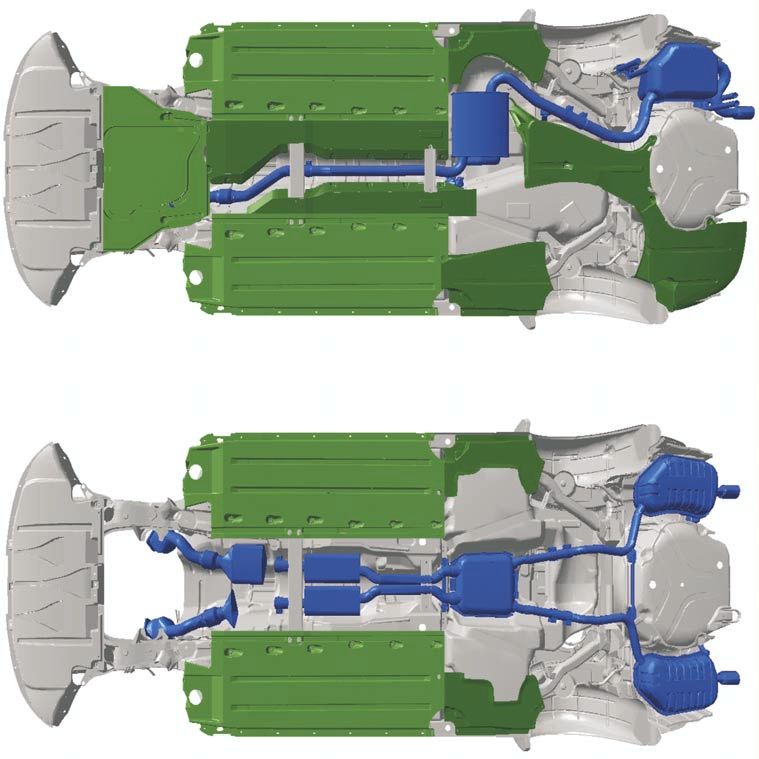
Wash/wipe system
The wash/wipe system is equipped with the The windscreen wash/wipe relays are inte-
speed-dependent 4-stage interval system. grated into the vehicle electrical system
control unit J519.
A new feature is the re-wipe function for the
windscreen washer system. The washer fluid reservoir is a two-part
Re-wiping occurs automatically 5 seconds design for easier removal and installation.
after the wash procedure is completed. An additional sensor is fitted for vehicles with
headlight washer system (HWS). In the
"highline" version, this is also used for the
Check system.
The purpose of the sensor, is to switch off the
HWS pump via the vehicle electrical system
control unit.
This prevents the pump running dry.
Reservoir in engine
compartment
Reservoir in front left
wheel housing
Connected
Windscreen washer fluid
Windscreen and level sender G33
rear screen washer
pump V58
Headlight washer sys-
tem pump V11 SSP254_024
56Control unit for trailer recognition J345
A separate control unit is required for trailer
operation. This transmits the vehicle lighting
system convenience CAN messages from the
vehicle electrical system control unit to the
trailer lights. A parallel link from the trailer
socket to the vehicle wiring would result in
fault detection via the microprocessor in the
vehicle electrical system control unit.
The diagnostic function of the control unit for
trailer recognition is performed via the
vehicle electrical system control unit J519,
address word 09.
SSP254_016
Address word 09 - vehicle electrical system/
Central convenience In the case of faulty communication
electronics between the control unit for trailer recog-
nition and the vehicle electrical system
Communication takes place by means of the control unit, the rear lights are actuated
convenience data bus via the central conven- as a warning signal.
ience electronics, as no separate K-wire
leads to the vehicle electrical system control
unit. For this reason, intact central conven-
ience electronics are essential for perform-
ing self-diagnosis.
J387
J386
Door control units
Vehicle self-diagnosis 09 – Electronic central electrics
8E0907279B
int. load module RDW 0811
Code 101
Dealership No. 6803
02 - Interrogate fault memory
03 - Final control diagnosis
04 - Basic setting
05 - Erase fault memory
06 - End output
07 - Encoding control unit
08 - Read measured value block
09 - Read individual measured value
10 - Adaption J388 J389
11 - Log-in procedure
Measuring
Skip Print Help
equipment
VAS 5051 Control unit for vehicle
electrical system J519
CAN
BUS
K wire Control unit for trailer
recognition J345
Central convenience
electronics J393
Steering wheel
electronics
R
T
module J453
SSP254_018
Steering column
switch module J527
57You can also read