Installation and Servicing Instructions Type C Boilers
←
→
Page content transcription
If your browser does not render page correctly, please read the page content below
Installation and Servicing
                                                                 Instructions

                                                                 Type C Boilers

                                                                 microGENUS HE 24 MFFI G.C.N: 47-116-37
                                                                 microGENUS HE 28 MFFI G.C.N: 47-116-38
                                                                 microGENUS HE 32 MFFI G.C.N: 47-116-39

                                                                 LEAVE THESE INSTRUCTIONS WITH
                                                                 THE END-USER

                             E       C

                                                             I
                                                     4
                                                 3
                                                         5
                                             2

                                     4
                                 3
                                                         6
                                         5

                                             1
                             2

                                         6
                             1

Country of destination: GB / IE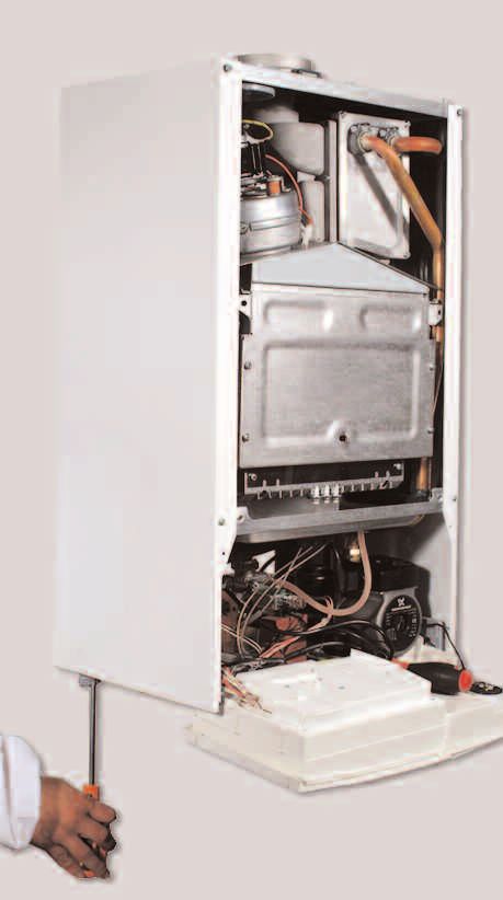
TABLE OF CONTENTS
1.     GENERAL INFORMATION                      PAGE. 3       6.3.8 REMOVING THE LATENT HEAT
1.1          GENERAL INSTRUCTIONS               PAGE. 3              EXCHANGER                         PAGE. 47
1.2          OVERALL VIEW                       PAGE. 4       6.3.9 REMOVING THE RECUPERATOR           PAGE. 48
                                                              6.3.10 REMOVING THE CONDENSATE TRAP      PAGE. 48
                                                           6.4       ACCESS TO THE GAS VALVE           PAGE. 49
2.     INSTALLATION                             PAGE. 4       6.4.1 REMOVING THE SPARK GENERATOR       PAGE. 49
2.1          REFERENCE STANDARDS                PAGE. 5       6.4.2 REMOVING THE GAS VALVE             PAGE. 49
2.2          SITING THE APPLIANCE               PAGE. 5    6.5       ACCESS TO THE WATER CIRCUIT       PAGE. 50
2.3          OVERALL DIMENSIONS                 PAGE. 6       6.5.1 REMOVING THE D.H.W. (SECONDARY)
2.4          CLEARANCES                         PAGE. 6            EXCHANGER                           PAGE. 50
2.5          MOUNTING THE APPLIANCE             PAGE. 6       6.5.2 REMOVING THE PUMP PRESSURE
2.6          ELECTRICAL CONNECTION              PAGE. 7              SWITCH                            PAGE. 51
2.7          GAS CONNECTION                     PAGE. 8       6.5.3 REMOVING THE SAFETY VALVE          PAGE. 51
2.8          WATER CONNECTION                   PAGE. 8       6.5.4 REMOVING THE AUTOMATIC AIR VENT    PAGE. 52
2.9          FLUE CONNECTION                    PAGE. 12      6.5.5 REMOVING THE PUMP                  PAGE. 52
2.10         CONTROL PANEL                      PAGE. 20      6.5.6 REMOVING THE PRESSURE GAUGE        PAGE. 53
2.11         DIGITAL DISPLAY AND FAULT CODES    PAGE. 20      6.5.7 REMOVING THE EXPANSION VESSEL      PAGE. 54
2.12         REMOVING THE FRONT PANEL           PAGE. 21      6.5.8 REMOVING THE OVERHEAT THERMOSTAT   PAGE. 54
2.13         ROOM THERMOSTAT CONNECTION         PAGE. 21      6.5.9 REMOVING THE C.H. TEMPERATURE
2.14         FITTING THE DIGITAL CLOCK          PAGE. 22             SENSOR (N.T.C.)                   PAGE. 55
2.15         SETTING THE MECHANICAL CLOCK       PAGE. 23      6.5.10 REMOVING THE D.H.W. TEMPERATURE
2.16         SETTING THE DIGITAL CLOCK          PAGE. 24             SENSOR (N.T.C.)                   PAGE. 55
2.17         ELECTRICAL/SYSTEM DIAGRAMS         PAGE. 25      6.5.11 REMOVING THE DIVERTER VALVE
2.18         WATER CIRCUIT DIAGRAM              PAGE. 27             ACTUATOR                          PAGE. 55
                                                              6.5.12 REMOVING THE D.H.W. FLOW
3.     COMMISSIONING                            PAGE. 28             SWITCH                            PAGE. 56
3.1          INITIAL PREPARATION                PAGE. 28   6.6       ACCESS TO THE CONTROL SYSTEM      PAGE. 56
3.2          INITIAL START-UP                   PAGE. 30      6.6.1 CHECKING THE FUSES                 PAGE. 56
3.3          OPERATIONAL ADJUSTMENTS            PAGE. 31      6.6.2 REMOVING THE P.C.B.                PAGE. 57
3.4          COMBUSTION ANALYSIS                PAGE. 31      6.6.3 REMOVING THE TIME CLOCK            PAGE. 58
3.5          PRODUCT OF COMBUSTION
             DISCHARGE MONITORING               PAGE. 31   7.    FAULT FINDING                         PAGE. 59
3.6          COMFORT MODE                       PAGE. 31   7.1     FAULT FINDING GUIDE (FLOW-CHARTS)   PAGE. 59
3.7          BOILER SAFETY SYSTEMS              PAGE. 32
3.8          DRAINING THE SYSTEM                PAGE. 33   8.    SHORT SPARE PARTS LIST                PAGE. 62
3.9          COMPLETION                         PAGE. 33
3.10         OPERATIONAL CHECKS                 PAGE. 33
3.11         INSTRUCTING THE END USER           PAGE. 34
                                                           9.    TECHNICAL INFORMATION                 PAGE. 65

                                                           10. BENCHMARK COMMISSIONING
4.     GAS ADJUSTMENTS                          PAGE. 35
4.1          CHANGING THE TYPE OF GAS           PAGE. 35
                                                               CHECKLIST               PAGE. 67
4.2          ADJUSTING THE GAS PRESSURES        PAGE. 36
                                                           11. SERVICE INTERVAL RECORD                 PAGE. 68
5.     MAINTENANCE                              PAGE. 40

6.     SERVICING INSTRUCTIONS                   PAGE. 41
6.1          REPLACEMENT OF PARTS               PAGE. 41
6.2          TO GAIN GENERAL ACCESS             PAGE. 41
   6.2.1     REMOVING THE FRONT PANEL           PAGE. 41
   6.2.2     REMOVING THE SEALED CHAMBER
             FRONT PANEL                        PAGE. 42
   6.2.3     REMOVING THE SIDE PANELS           PAGE. 42
6.3          ACCESS TO THE COMBUSTION CHAMBER   PAGE. 43
   6.3.1     REMOVING THE COMBUSTION
             CHAMBER                            PAGE. 43
     6.3.2   REMOVING THE BURNER AND JETS       PAGE. 43
     6.3.3   REMOVING THE ELECTRODES            PAGE. 43
     6.3.4   REMOVING THE MAIN HEAT EXCHANGER   PAGE. 44
     6.3.5   REMOVING THE AIR PRESSURE SWITCH   PAGE. 45
     6.3.6   REMOVING THE FAN                   PAGE. 46
     6.3.7   REMOVING THE FUME SENSOR           PAGE. 46

2
1. GENERAL INFORMATION
                                                               1.1     GENERAL INSTRUCTIONS
This manual is an integral and essential part of the
product. It should be kept with the appliance so that it can   Read the instructions and recommendations in these
be consulted by the user and our authorised personnel.         Installation and Servicing Instructions carefully to ensure
                                                               proper installation, use and maintenance of the
Please carefully read the instructions and notices about       appliance.
the unit contained in this manual, as they provide
important information regarding the safe installation, use     Keep this manual in a safe place. You may need it for your
and maintenance of the product.                                own reference while Servicing Technicians or your
                                                               installer may need to consult it in the future.
For operating instructions please consult the separate End     This is a condensing combined appliance for the
User Manual.                                                   production of central heating (C.H.) and domestic hot
                                                               water (D.H.W.).
                                                               This appliance must be used only for domestic use.
                                                               The manufacturer declines all liability for damage caused
                                                               by improper or negligent use.
                                                               No asbestos or other hazardous materials have been
                                                               used in the fabrication of this product.
                                                               MTS recommends the use of protective clothing when
                                                               installing and working on this appliance i.e. gloves.
                                                               Before connecting the appliance, check that the
                                                               information shown on the data plate and the table in
                                                               Section 8 comply with the electric, water and gas mains
                                                               of the property. You will find the data plate on the reverse
                                                               of the control panel.
                                                               The gas with which this appliance operates is also shown
                                                               on the label at the bottom of the boiler.
                                                               Do not install this appliance in a damp environment or
                                                               close to equipment which spray water or other liquids.
                                                               Do not place objects on the appliance.
                                                               Do not allow children or inexperienced persons to use
                                                               the appliance without supervision.
                                                               If you smell gas in the room, do not turn on or off light
                                                               switches, use the telephone or any other object which
                                                               might cause sparks.
                                                               Open doors and windows immediately to ventilate the
                                                               room.
                                                               Shut the gas mains tap (at or adjacent to the gas meter)
                                                               or the valve of the gas cylinder and call your Gas Supplier
                                                               immediately.
                                                               If you are going away for a long period of time, remember
                                                               to shut the mains gas tap or the gas cylinder valve.
                                                               Always disconnect the appliance either by unplugging it
                                                               from the mains or turning off the mains switch before
                                                               cleaning the appliance or carrying out maintenance.
                                                               In the case of faults or failure, switch off the appliance
                                                               and tur n off the gas tap. Do not tamper with the
                                                               appliance.
                                                               For repairs, call your local Authorised Servicing Agent
                                                               and request the use of original spare parts. For in-
                                                               guarantee repairs contact MTS (GB) Limited.

                                                                                                                         3
1.2        OVERALL VIEW

                                           LEGEND:
      1                           28
                                           1.    Flue Manifold
                                           2.    Air Intake for Twin Pipe Flue Systems
      2                           27       3.    Fan
                                           4.    Combustion Chamber Hood
      3                           26       5.    Main Heat Exchanger
                                           6.    Overheat Thermostat
                                           7.    Central Heating Flow Temperature Probe
      4                           25       8.    Combustion Chamber Insulation Panel
                                           9.    Burner
      5                                    10.   Detection Electrode
      6                                    11.   Ignition Electrodes
                                           12.   Motorised Valve
      7
                                  24       13.   Condensate trap
      8                                    14.   Domestic Hot Water Temperature Probe
                                           15.   Low Water Pressure Switch
      9                                    16.   Secondary Heat Exchanger
                                           17.   Gas Valve
      10                          23       18.   Spark Generator
      11                                   19.   Cold Water Inlet Filter
      12                          22       20.   Pump (w/auto air vent)
                                  21       21.   Safety Valve
      13                                   22.   D.H.W. Flow Switch
      14                          20       23.   Condensate Trap Tube
                                           24.   Combustion Chamber
                                           25.   Condensate Sensor
                                           26.   Latent Heat Collector
               15 16 17 18 19              27.   Air Pressure Switch
                                FIG. 1.0   28.   Combustion Analysis Test Point

4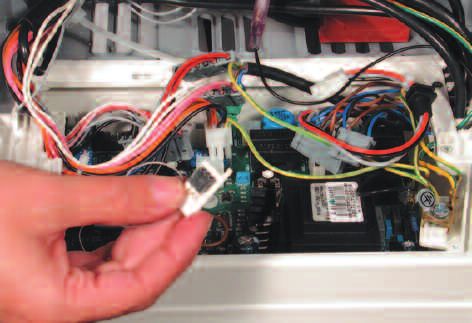
2.          INSTALLATION

2.1         REFERENCE STANDARDS                                 2.2     SITING THE APPLIANCE

The technical information and instructions provided             The appliance may be installed in any room or indoor
herein below are intended for the installer / Servicing         area, although par ticular attention is drawn to the
Technician so that the unit may be installed and serviced       requirements of the current I.E.E. Wiring Regulations, and
correctly and safely.                                           in Scotland, the electrical provisions of the Building
                                                                Regulations applicable in Scotland, with respect to the
In the United Kingdom the installation and initial start up     installation of the combined appliance in a room
of the boiler must be by a CORGI Registered Installer in        containing a bath or shower, the location of the boiler in a
accordance with the installation standards currently in         room containing a bath or shower should only be
effect, as well as with any and all local health and safety     considered if there is no alternative.
standards i.e. CORGI.
                                                                Where a room-sealed appliance is installed in a room
In the Republic of Ireland the installation and initial start   containing a bath or shower the appliance and any
up of the appliance must be carried out by a Competent          electrical switch or appliance control, utilising mains
Person in accordance with the current edition of I.S.813        electricity should be situated so that it cannot be
“Domestic Gas Installations”, the current Building              touched by a person using the bath or shower,
Regulations, reference should also be made to the               specifically in accordance with current IEE Wiring
current ETCI rules for electrical installation.                 Regulations.

This appliance must be installed by a competent                 The location must permit adequate space for servicing
installer in accordance with current Gas Safety                 and air circulation around the appliance as indicated in
(installation & use) Regulations.                               Section 2.4.
                                                                The location must permit the provision of an adequate
                                                                flue and termination.
The installation of this appliance must be in accordance
                                                                For unusual locations special procedures may be
with the relevant requirements of the Local Building
                                                                necessary.
Regulations, the current I.E.E. Wiring Regulations, the
                                                                BS 6798-2000 gives detailed guidance on this aspect.
bylaws of the local water authority, in Scotland, in
                                                                A compartment used to enclose the appliance must be
accordance with the Building Standards (Scotland)
                                                                designed specifically for this purpose. No specific
Regulation and Health and Safety document No. 635
                                                                ventilation requirements are needed for the installation
“Electricity at work regulations 1989” and in the Republic
                                                                within a cupboard.
of Ireland with the current edition of I.S. 813, the Local
                                                                This appliance is not suitable for outdoor installation.
Building Regulations (IE).
                                                                The type C appliances (in which the combustion
C.O.S.H.H.
                                                                circuit, air vent intake and combustion chamber are
                                                                air-tight with respect to the room in which the
Materials used in the manufacture of this appliance are
                                                                appliance is installed) can be installed in any type of
non-hazardous and no special precautions are required
                                                                room. However, as the appliance has many
when servicing.
                                                                functioning components, pay particular attention
Installation should also comply with the following British
                                                                when siting the appliance in room such as bedrooms
Standard Codes of Practice
                                                                as operating noise may be a nuisance.
BS 7593:1992   Treatment of water in domestic hot water
               central heating systems
                                                                Secondary ventilation is not required with this boiler. The
BS 5546:1990 Installation of hot water supplies for             boiler must be installed on a solid, non-combustible,
               domestic purposes                                permanent wall to prevent access from the rear.
BS 5440-1:2000 Flues
BS 5440-2:2000 Air supply
BS 5449:1990 Forced circulation hot water systems
BS 6798:2000 Installation of gas fired hot water boilers
               of rated input not exceeding 60kW
BS 6891:1989 Installation of low pressure gas pipe up to
               28mm
BS 7671:2001 IEE wiring regulations
BS 4814:1990 Specification for expansion vessels
BS 5482:1994 Installation of L.P.G.

and in the Republic of Ireland in accordance with the
following Codes of Practice:

 I.S. 813         Domestic Gas Installations

                                                                                                                          5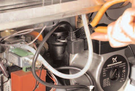
2.3     OVERALL DIMENSIONS

                 LEGEND:

                 A = Central Heating Flow (3/4” - 22mm Copper Tail)
                 B = Domestic Hot Water Outlet (1/2” - 15mm Copper Tail)
                 C = Gas Inlet (3/4” - 15mm Copper Tail)
                 D = Domestic Cold Water Inlet (1/2” - 15mm Copper Tail)
                 E = Central Heating Return (3/4” - 22mm Copper Tail)

           120

FIG. 2.1

                 2.4     CLEARANCES

                 In order to allow access to the interior of the boiler for
                 maintenance purposes, the boiler must be installed in
                 compliance with the minimum clearances indicated in FIG. 2.2

FIG. 2.2

                 2.5     MOUNTING THE APPLIANCE
                 After removing the boiler from its packaging, remove the
                 template from the separate box containing the connection
                 kit. NOTE: Pay particular attention to any test water that
                 may spill from the appliance.

                 Place the template in the position the appliance is to be
                 mounted and after ensuring it is hanging squarely, use it
                 to mark the holes for the hanging bracket, connection kit
                 and flue pipe(s) NB: For further information relating to the
                 flue installation please refer to Section 2.9 F L U E
                 CONNECTION. (If the appliance is to be fitted on a wall of
                 combustible material, the wall must be protected by a
                 sheet of fireproof material).
                 If the appliance is to be fitted into a timber framed
                 building, guidance should be sought from the Institute of

6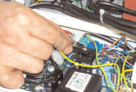
Gas Engineers document REF: IGE/UP/7.

           2.5.1. Drill the wall and plug using those supplied with
           the connections kit, position the hanging bracket and
           secure with the wall bolts supplied, assemble the
           connection kit and secure to the wall. NOTE: It is highly
           recommended that a spirit level be used to position the
           appliance to ensure that it is perfectly level.

           2.5.2. Position the appliance on the hanging bracket
           and connect the connection kit to the boiler connections.
           (see also Sections 2.7 Gas Connections, 2.8 Water
           Connections & FIG. 2.3).

           2.6     ELECTRICAL CONNECTION
           For safety purposes, have a competent person carefully
           check the electrical system in the proper ty, as the
           manufacturer will not be held liable for damage caused by
           the failure to earth the appliance properly or by anomalies
           in the supply of power. Make sure that the residential
           electrical system is adequate for the maximum power
           absorbed by the unit, which is indicated on the rating
           plate. In addition, check that the section of cabling is
           appropriate for the power absorbed by the boiler.

           The boiler operates with alternating current, as indicated
           in the Technical Information table in Section 10, where the
           maximum absorbed power is also indicated. Make sure
           that the connections for the neutral and live wires
           correspond to the indications in the diagram. The
           appliance electrical connections are situated on the
           reverse of the control panel.

           IMPORTANT!
           In the event that the power supply cord must be changed,
           replace it with one with the same specifications.
           Note: The diagrams for the electrical system are indicated
FIG. 2.3   in section 2.13.

           Warning, this appliance must be earthed.

           External wiring to the appliance must be carried out by a
           competent person and be in accordance with the current
           I.E.E. Regulations and applicable local regulations.
           The appliance is supplied with a fly-lead already
           connected, this must be connected to a 240v supply
           fused at 3A and must facilitate complete electrical
           isolation of the appliance, by the use of a fused double
           pole isolator having a contact separation of at least 3 mm
           in all poles or alternatively, by means of a 3 A fused
           three pin plug and unswitched, shuttered socket outlet
           both complying with BS 1363.
           The point of connection to the Electricity supply must be
           readily accessible and adjacent to the appliance unless
           the appliance is installed in a bathroom when this must
           be sited outside the bathroom (see section 2.2).

           Should external controls be required, the design of the
           external electrical circuits should be undertaken by a
           competent person, see Section 2.13 for fur ther
           information.

                                                                    7
2.7       GAS CONNECTION

                                                The local gas region contractor connects the gas meter to
                                                the service pipe.
                                                If the gas supply for the boiler serves other appliances
                                                ensure that an adequate supply is available both to the
                                                boiler and the other appliances when they are in use at
                                                the same time.
                                                Pipe work must be of an adequate size. Pipes of a
                                                smaller size than the boiler inlet connection should not be
                                                used.

                                                2.8       WATER CONNECTIONS
                                                            VIEW OF THE BOILER CONNECTIONS
                                                LEGEND:
                                                A = Central Heating Flow
                                                B = Domestic Hot Water Outlet
                                                C = Gas Inlet
               G                                D = Domestic Cold Water Inlet
                       C                        E = Central Heating Return
           A       B       D   E                F = Condensate discharge
                                                G = Drain valve
                                                H = Safety Valve Outlet
     F                             H
                                                CENTRAL HEATING
                                                Detailed recommendations are given in BS 6798:2000
                                                and BS 5449-1:1990, the following notes are given for
FIG. 2.4                                        general guidance.

                                                PIPE WORK:
                                                Copper tubing to BS EN 1057:1996 is recommended for
                                                water pipes. Jointing should be either with capillary
                                                soldered or compression fittings.
                                                Where possible pipes should have a gradient to ensure
                                                air is carried naturally to air release points and water
                                                flows naturally to drain taps.
                                                The appliance has a built-in automatic air release valve,
                                                however it should be ensured as far as possible that the
                                                appliance heat exchanger is not a natural
                                                collecting point for air.
                                                Except where providing useful heat, pipes should be
                                                insulated to prevent heat loss and avoid freezing.
                                                Particular attention should be paid to pipes passing
                                                through ventilated spaces in roofs and under floors.

                                                BY-PASS:
                                                The appliance includes an automatic by-pass valve,
                                                which protects the main heat exchanger in case of
                                                reduced or interrupted water circulation through the
FIG. 2.5                               KT007A
                                                heating system, due to the closing of thermostatic valves
                                                or radiators.

                                                SYSTEM DESIGN:
                                                This boiler is suitable only for sealed systems.

                                                DRAIN COCKS:
                                                These must be located in accessible positions to permit
                                                the draining of the whole system and should be fitted at
                                                all low points. The taps must be at least 15mm nominal
                                                size and manufactured in accordance with BS 2870:1980.

8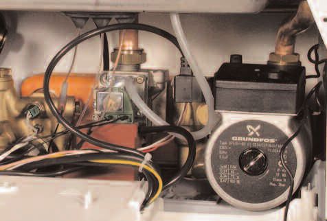
SAFETY VALVE DISCHARGE:                                            as above.
The discharge should terminate facing downward on the         iii) Terminating into a gully, below the grid level but above
exterior of the building in a position where discharging           the water level.
(possibly boiling water & steam) will not create danger or    iv)Into a soakway.
nuisance, but in an easily visible position, and not cause
damage to electrical components and wiring.                   N OTE : If any condensate pipe work is to be installed
The discharge must not be over an entrance or a window           externally, then it should be kept to a minimum and be
or any other type of public access.                              insulated with a waterproof insulation and have a
                                                                 continuous fall.
CONDENSATE DISCHARGE:
A flexible hose connected to the bottom of the boiler           Some examples of the type of condensate drains can
should be inserted into a tundish (not supplied).               be found on pages 10 and 11.

NOTE: IT   MAY BE NECESSARY TO REMOVE THE CASING TO PULL      AIR RELEASE POINTS:
THE CONDENSATE HOSE OUT OF THE BOTTOM OF THE BOILER.          These must be fitted at all high points where air naturally
                                                              collects and must be sited to facilitate complete filling of
The condensate discharge hose from the boiler must            the system.
have a continuous fall of at least 2.5° and must be           The appliance has an integral sealed expansion vessel to
connected to a visible tundish and inserted by at least       accommodate the increase of water volume when the
50mm into a suitable acid resistant pipe with a nominal       system is heated.
diameter of 32mm e.g. plastic waste pipe or overflow          It can accept up to 6 litres (1.3 gal) of expansion water. If
pipe. The condensate discharge pipe must have a               the heating circuit has an unusually high water content,
continuous fall and preferably be installed and terminated    calculate the total expansion and add an additional
within the building to prevent freezing.                      sealed expansion vessel with adequate capacity. This
The discharge pipe must be terminated in one of the           should be located on the return pipe work as close as
following positions, allowing for a safe discharge:           possible to the pump inlet.
i) Connecting in to an internal soil stack (at least 450 mm
    above the invert of the stack). A trap giving a water     MAINS WATER FEED - CENTRAL HEATING:
    seal of at least 75 mm must be incorporated into the      A method for initially filling the heating system is supplied
    pipe run, there also must be an air break upstream of     with the connection kit. The filling loop is connected
    the trap i.e. tundish.                                    between the cold water inlet and the central heating flow
ii) Connecting into the waste system of the building such     connections, and incorporates a non-return valve. To
    as a washing machine or sink trap. The connection         operate the filling loop, it is necessary to open both
    must be upstream of the washing machine/sink (If the      quarter turn handles, once the required pressure has
    connection is down stream of the waste trap then an       been achieved, close both handles and disconnect the
    additional trap giving a minimum water seal of 75 mm      hose in accordance with water byelaws. N OTE : The
    and an air break must be incorporated in the pipe run,    installer should ensure that there are no leaks as

                                 RESIDUAL HEAD OF THE BOILER ∆T 20°C

    VR003A                                                                                                  FIG. 2.6

                                                                                                                         9
1. Internal termination of condensate drainage pipe to                  frequent filling of the heating system can lead to
   internal stack                                                       premature scaling of the main exchanger and failure of
                                                                        hydraulic components.

                                                                        DOMESTIC WATER:
                                                                        The domestic water must be in accordance with the
                                                                        relevant recommendation of BS 5546:1990. Copper
                                                                        tubing to BS EN 1057:1996 is recommended for water
         E           C
                                                                        carrying pipe work and must be used for pipe work
             3   4
                                 3   4
                                             I

                                                                        carrying drinking water, a scale reducer should also be
                                         5
                             2
     2

                         5

                             1

                                         6
                         6
     1

                                                                        used to reduce the risk of scale forming in the domestic
                                                                        side of the heat exchanger.

                                                                        WATER TREATMENT
                                                                        The boiler is equipped with an aluminium alloy main heat
                                                                        exchanger.
                                                                        The detailed recommendations for water treatment are
                                                                        given in BS 7593:1992 (Treatment of water in domestic
                                                                        hot water central heating systems); the following notes
                                                                        are given for general guidance;

                                                                        - If the boiler is installed on an existing system, any
                                                                          unsuitable additives must be removed;
  2. External termination of condensate drainage pipe via
     internal discharge branch (e.g. sink waste) and condensate
                                                                        - Under no circumstances should the boiler be fired
     siphon                                                               before the system has been thoroughly flushed; the
                                                                          flushing procedure must be in line with BS7593:1992.
                                                                          We highly recommend the use of a flushing detergent
                                                                          appropriate for the metals used in the aluminium alloy
                                                                          circuit. These include (Fernox Superfloc, BetzDearborn
                                                                          Sentinel X300 or X400), whose function is to dissolve
                                                                          any foreign matter that may be in the system;
                                                                          In hard water areas or where large quantities of water
                                                                          are in the system the treatment of the water to prevent
                                                                          premature scaling of the main heat exchanger is
                                                                          necessary.

                                                                          The formation of scale strongly compromises the
                                                                          efficiency of the thermic exchange because small
                                                                          areas of scale cause a high increase of the
                                                                          temperature of the metallic walls and therefore add to
                                                                          the thermal stress of the heat exchanger.
                                                                          Demineralised water is more aggressive so in this
                                                                          situation it is necessary to treat the water with an
                                                                          appropriate corrosion inhibitor.
                                                                        - Any treatment of water by additives in the system for
3. External termination of condensate drainage pipe via
   internal discharge branch (e.g. sink waste - proprietary fitting).     frost protection or for corrosion inhibition has to be
                                                                          absolutely suitable for all the metals used in the circuit
                                                                          including the aluminium alloys.
                                                                          The use of a corrosion inhibitor in the system such as
                                                                          Fernox MB-1, BetzDeaborn Sentinel X100 or Fernox
                                                                          System Inhibitor is recommended to prevent corrosion
                                                                          (sludge) damaging the boiler and systems;
                                                                        - If anti-freeze substances are to be used in the system,
                                                                          check carefully that they are compatible with the
                                                                          aluminium.
                                                                          In par ticular, DO NOT USE ordinary ETHYLENE
                                                                          GLYCOL, since it is corrosive in relation to aluminium
                                                                          and its alloy, as well being toxic.
                                                                          MTS suggests the use of suitable anti-freeze products
                                                                          such as Fernox ALPHI 11, which will prevent rust and
                                                                          incrustation taking place.
                                                                          Periodically check the pH of the water/anti-freeze

10
4. External termination of condensate drainage pipe via mixture of the boiler circuit and replace it when the
condensate siphon amount measured is out of the range stipulated by the
manufacturer ( 7 < pH < 8).
DO NOT MIX DIFFERENT TYPES OF ANTI-FREEZE
- In under-floor systems, the use of plastic pipes without
protection against penetration of oxygen through the
walls can cause corrosion of the system’s metal parts (
metal piping, boiler, etc), through the formation of
oxides and bacterial agents.
To prevent this problem, it is necessary to use pipes
with an “oxygen-proof barrier”, in accordance with
standards DIN 4726/4729. If pipes of this kind are
not used, keep the system separate by installing
heat exchangers of those with a specific system
water treatment.
IMPORTANT
Failure to carry out the water treatment procedure will
invalidate the appliance warranty.
112.9. CONNECTING THE FLUE FLUE SYSTEM
The provision for satisfactory flue termination must be made as
described in BS 5440-1.
The appliance must be installed so that the flue terminal is exposed to
IMPORTANT!! outdoor air.
BEFORE CONNECTING THE FLUE, ENSURE THAT 1 LITRE OF The terminal must not discharge into another room or space such as
an outhouse or lean-to.
WATER HAS BEEN POURED INTO THE EXHAUST CONNECTION TO
It is important that the position of the terminal allows a free passage
FILL THE CONDENSATE TRAP (FIG.2.7). SHOULD THE TRAP BE
of air across it at all times.
EMPTY THERE IS A TEMPORARY RISK OF FLUE GASSES The terminal should be located with due regard for the damage or
ESCAPING INTO THE ROOM. discolouration that might occur on buildings in the vicinity, it must
also be located in a place not likely to cause nuisance.
In cold or humid weather water vapour will condense on leaving the
flue terminal.
The effect of such “steaming” must be considered.
If the terminal is less than 2 metres above a balcony, above ground
or above a flat roof to which people have access, then a suitable
stainless steel terminal guard must be fitted.
The minimum acceptable spacing from the terminal to obstructions
and ventilation openings are specified in Fig. 2.8.
Note: In cold weather the condensate could cause a safety hazard if
it freezes on pathways or if it results in frost damage to
surfaces and the plume could trigger infra-red security lighting
if sited in the wrong place.
FIG. 2.7
TERMINAL POSITION mm
A- Directly below an open window or other opening 300
B- Below gutters, solid pipes or drain pipes 75
C- Below eaves 200
D- Below balconies or car-port roof 200
E- From vertical drain pipes and soil pipes 75
F- From internal or external corners 300
G- Above ground or below balcony level 300
H- From a surface facing a terminal 600
I- From a terminal facing a terminal 1200
J- From an opening in the car port
(e.g. door, window) into dwelling 1200
K- Vertically from a terminal in the same wall 1500
FIG. 2.8 L- Horizontally from a terminal in the same wall 300
M- Horizontally from an opening window 300
N- Fixed by vertical flue terminal
Ø 60/100 mm
4
FIG. 2.9
12Warning Important
The exhaust gas ducts must not be in contact with or close to Ensure that the flue is not blocked.
inflammable material and must not pass through building Ensure that the flue is supported and assembled in
structures or walls made of inflammable material. accordance with these instructions.
When replacing an old appliance, the flue system must be
changed.
Level
Installation without extension
118
150 mm
FIG. 2.10
Installation with extension Level
* slope
150 mm
* slope 5 mm per metre
FIG. 2.11
CONTENTS:
2.9.1 FITTING THE COAXIAL FLUE 1X SILICONE O-RING (60mm)
(Ø 60 / 100 HORIZONTAL)
1X ELBOW (90 ) O
2X WALL SEALS (INTERNAL & EXTERNAL)
1X FLUE PIPE INCLUDING TERMINAL (1 METRE - 60/100)
1X FLUE CLAMP
2X SCREWS
1x Seal
Once the boiler has been positioned on the wall, insert the elbow
into the socket and rotate to the required position. NOTE: It is
possible to rotate the elbow 360o on its vertical axis.
Using the flue clamp, seals and screws supplied (Fig 2.12)
secure the elbow to the boiler.
The 1 metre horizontal flue kit (3318073) supplied is suitable for
an exact X dimension of 823 mm.
Measure the distance from the face of the external wall to the
face of the flue elbow (X - Fig 2.9), subtract 48 mm from this
measurement, you now have the total length of flue required
(including the terminal), this figure must now be subtracted from
907mm, you now have the total amount to be cut from the plain
end of the flue.
Cut the flue to the required length ensuring that the distance
between the inner and the outer flue is maintained (Fig 2.12).
e.g.
X = 508mm - 48mm = 460mm
823 - 460 = 363mm (Length to be cut from the plain end of
the flue).
Once cut to the required length, ensure that the flue is free from
burrs and reassemble the flue. If fitting the flue from inside of the
building attach the grey outer wall seal to the flue terminal and
push the flue through the hole, once the wall seal has passed
through the hole, pull the flue back until the seal is flush with the
wall. Alternatively, the flue can be installed from outside of the
building, the grey outer seal being fitted last.
13Clamp
Screws
Seal FIG. 2.12
Should the flue require extending, the flue connections are push
fit, however, one flue bracket should be used to secure each
metre of flue.
2.9.2 FITTING THE 5” FLUE (Ø 80 / 125
HORIZONTAL / VERTICAL) NOTE: SEE PAGE 19 FOR MAXIMUM AND MINIMUM FLUE RUNS.
Once the boiler has been positioned on the wall, it is necessary
to insert the Ø80/125 adaptor (FIG. 2.13) for both horizontal and
vertical flue runs into the boiler flue socket (not supplied with flue
kit - Part No 3318095).
Push the adaptor onto the boilers flue connection, grease the
seals then add extensions or elbows as required, secure the
adaptor, using the clamp and screws provided.
To fit extensions or elbows it is first necessary to ensure that the
lip seal is fitted correctly into the inner flue, once verified, it is
simply necessar y to push them together, no clamps are
necessary to secure the flue components.
Before proceeding to fit the flue, ensure that the maximum flue
length has not been exceeded (See the tables on Page 19) and
that all elbows and bends have been taken into consideration, the
maximum flue length is 10 metres, for each additional 90o elbow
1 metre must be subtracted from the total flue length, and for
each 45o 0.5 metres must be subtracted from the total flue length
(the height of the vertical adaptor and a 45 o bend can be
seen in Fig. 2.14 and a 90o bend in Fig. 2.15).
FIG. 2.13 NOTE: DO NOT CUT THE VERTICAL FLUE KIT.
FIG. 2.14
14NOTE: SEE PAGE 19 FOR MAXIMUM AND MINIMUM FLUE RUNS.
2.9.3. FITTING THE COAXIAL FLUE
(Ø 60 / 100 VERTICAL) CONTENTS:
1X SILICONE O-RING (60mm)
1X CONICAL ADAPTOR (60/100mm)
1X VERTICAL FLUE KIT (80/125mm)
3X SCREWS
The vertical flue kit is supplied with a specially designed weather
proof terminal fitted, it can be used either with a flat roof or a
pitched roof.
The Vertical flue kits useable lengths with the pitched roof
flashings are indicated in Fig. 2.15.
Before proceeding to fit the flue, ensure that the maximum flue
length has not been exceeded (See the tables on Page 19) and
that all elbows and bends have been taken into consideration, the
maximum flue length is 4 metres, for each additional 90o elbow 1
metre must be subtracted from the total flue length, and for each
45o 0.5 metres must be subtracted from the total flue length (the
height of the vertical adaptor and a 45o bend can be seen in
Fig. 2.16).
Mark the position of the flue hole in the ceiling and/or roof (see
Fig. 2.15 for distance from wall to the centre of the flue).
Cut a 120mm diameter hole through the ceiling and/or roof and fit
the flashing plate to the roof.
FIG. 2.15
DO NOT cut the vertical flue kit.
To connect the vertical flue kit directly to the boiler, place the
vertical starter kit (Part No. 3318079) (see Fig. 2.16) onto the
exhaust manifold and secure with the clamp, fit the vertical
adaptor onto the vertical starter kit (note: there is no need to use
a clamp to secure this as it is a push fit connection), the vertical
flue kit must then be inserted through the roof flashing, this will
ensure that the correct clearance above the roof is provided as
the terminal is a fixed height.
Should extensions be required, they are available in 1 metre
(Part No. 3318077), 500mm (Part No. 3318078) and 160mm
lengths, they must be connected directly to the vertical starter kit
before connecting the adaptor to allow the vertical flue kit to be
fitted. In the event that extension pieces need to be shortened,
they must only be cut at the male end and it must be ensured
that the distance between the inner and outer flue is maintained
(Fig. 2.12).
When utilising the vertical flue system, action must be taken to
ensure that the flue is supported adequately to prevent the
weight being transferred to the appliance flue connection by
using 1 flue bracket per extension.
When the flue passes through a ceiling or wooden floor, there
must be an air gap of 25mm between any part of the flue system
and any combustible material. The use of a ceiling plate will
FIG. 2.16 facilitate this. Also when the flue passes from one room to
another a fire stop must be fitted to prevent the passage of
smoke or fire, irrespective of the structural material through which
the flue passes.
15NOTE: SEE PAGE 19 FOR MAXIMUM AND MINIMUM FLUE RUNS.
2.9.4. FITTING THE TWIN PIPE (Ø80 / 80)
Where it is not possible to terminate the flue within the distance
permitted for coaxial flues, the twin flue pipe can be used by
fitting a special adaptor to the flue connector and using the
aperture for the air intake located on top of the combustion
chamber.
Always ensure that the flue is adequately supported, avoiding low
points. (MTS supply suitable clamps as Part No. 705778).
To utilise the air intake it is necessary to:
1) Take the air intake cover off
2) Assemble the flange on the header supplied with the boiler
3) Insert the restrictor if necessary, on the tube or the elbow
4) Insert the header on the tube or the elbow up until the lower
stop
(you do not have to use the washer).
5) Insert the elbow/header in the boiler air intake hole and fasten
it with screws.
The twin flue pipes can be fitted with or without additional elbows
and need no clamps, simply ensure that the red o-ring is inserted
in the female end of the flue pipe and push the extension piece
fully into the previous section of flue pipe or elbow, check that the
o-ring is not dislodged when assembling the flue.
Twin pipe can also be converted back to Coaxial flue to enable
vertical termination with a coaxial kit by using the pipe bridge
(Twin - Coaxial Adaptor - Part No. 705767). When running the
twin flue pipe vertically.
It is not recommended that the pipe bridge be used for horizontal
termination, however in the unlikely event that this proves to be a
necessity it is extremely important that the entire flue has a fall of
5mm in every metre back to the boiler, and where the 60mm
inner flue of the concentric terminal connects to the pipe bridge,
this point must be adequately sealed with silicone sealant to
avoid condense leakage at this point.
When siting the twin flue pipe, the air intake and exhaust
terminals must terminate on the same wall, the centres of the
terminals must be a minimum of 280 mm apart and the air intake
must not be sited above the exhaust terminal (refer to Fig. 2.19).
The air intake pipe can be run horizontally, however, the terminal
and the final 1 metre of flue must be installed with a fall away
from the boiler to avoid rain ingress.
It is also strongly recommended that the air intake pipe run be
constructed of insulated pipe to prevent condense forming on the
outside of the tube.
The maximum permissible flue length for twin flue is dependent
on the type of run used.
For flue runs with the intake and exhaust pipes under the same
atmospheric conditions (T YPE 4) the maximum length is 40
metres (27kW) and 48 metres (32kW), for runs with the terminals
under different atmospheric conditions (TYPE 5) the exhaust
terminal must extend 0.5 metres above the ridge of the roof (this
is not obligatory if the exhaust and air intake pipes are located on
the same side of the building). For TYPE 5 also, the maximum
permissible combined length is 40 metres (27kW) and 49 metres
(32kW).
The maximum length is reached by combining the total lengths of
both the air intake and exhaust pipes. Therefore a maximum
length of 40 metres for example, will allow a flue run of 20 metres
for the air
o
intake and 20 metres for the exhaust pipes, also for
each 90 elbow 2.2 metres must be subtracted from the total
length and for each 45o elbow 1.4 metres must be subtracted
from the total flue length.
Some of the acceptable flue configurations are detailed on page
20.
16For further information relating to flue runs not illustrated, please
230 MIN * 123,5 135 contact the Technical Department on 0870 241 8180.
200
132
Fig. 2.17
ø 100
In the event that twin flue pipes are used, and the boiler
has a side clearance of less than 60mm from the wall, it
is necessary to cut a larger diameter hole for the flue
pipe, this should be ø10 cm, this will then allow for easier
assembly of the air intake elbow and the tube outside the
wall (see Fig. 2.17).
60 mm
FIG. 2.18
AIR INTAKE MUST NOT BE
FITTED ABOVE THE EXHAUST
AIR INTAKE EXHAUST
AIR INTAKE
FIG. 2.19
17For coaxial systems, the maximum Use the Do not use
Maximum
development value, mentioned in the 24 MFFI Exhaust Type ø 40 mm the
Flue Length
table above also takes into account Restrictor(*) Restrictor
an elbow.
For twin flue systems the maximum Type 1
development value, mentioned in the
Coaxial
table includes the exhaust gas/air Between Between
intake terminal. Systems Type 2 4m
500 mm - 1 m 1m-4m
ø 60/100
Type 5 outlets should respect the Type 3
following instructions:
1- Use the same ø 80 mm flue pipes
for the gas intakes and exhaust gas
Type 1
ducts. Coaxial
2- If you need to insert elbows in the Systems Type 2 TBC TBC 10 m
gas intake and exhaust gas ducts, ø 80/125
you should consider for each one the
equivalent length to be included in the
Type 3
calculation of developed length.
3- The exhaust gas duct should jut Between Between
Twin Pipe Type 4 10 m - 40 m 40 m
above the roof by at least 0.5 m. 1m - 10 m
4- The intake and exhaust gas ducts
Systems
ø 80/80 Between Between
in Type 5 must be installed on the Type 5 10 m - 40 m 40 m
same wall, or where the exhaust is
1m - 10 m
vertical and the air intake horizontal,
Use the Do not use
the terminals must be on the same Maximum
side of the building. 28 MFFI Exhaust Type ø 41 mm the
Flue Length
Restrictor(*) Restrictor
Type 1
Coaxial
Between Between
Systems Type 2 4m
There are some different types of flue 500 mm - 1 m 1m-4m
systems shown on Page 19. ø 60/100
For additional information regarding the Type 3
flue accessories, please consult the Flue
Pipe Accessories manual.
Coaxial
Systems TBC TBC 10 m
ø 80/125
Between Between
Twin Pipe Type 4 10 m - 40 m 40 m
1m - 10 m
Systems
ø 80/80 Between Between
Type 5 10 m - 40 m 40 m
1m - 10 m
Use the Do not use
Maximum
32 MFFI Exhaust Type ø 43 mm the
Flue Length
Restrictor(*) Restrictor
Type 1
Coaxial
Between Between
Systems Type 2 4m
500 mm - 1 m 1m-4m
ø 60/100
Type 3
Type 1
Coaxial
Systems Type 2 TBC TBC 10 m
ø 80/125
Type 3
Between Between
Twin Pipe Type 4 10 m - 40 m 40 m
1m - 10 m
Systems
ø 80/80 Between Between
Type 5 10 m - 40 m 40 m
1m - 10 m
180
1
TYPE 1 TYPE 2 TYPE 3
TYPE 4 TYPE 5
NOTE: DRAWINGS ARE INDICATIVE OF FLUEING OPTIONS ONLY.
192.10 CONTROL PANEL
I J K
LEGEND:
A- On/Off Button
E C
B- Domestic Hot Water Temperature Adjustment
C- Central Heating Temperature Adjustment
I
D- Reset Button/Flue Test analysis mode*
3 4
3 4
E- Comfort Mode Selector
5
2
2
5
F- Summer Mode LED (Green)
1
6
6
1
G- Ignition/Overheat Lockout LED (Red)
H- Central Heating (Winter Mode) LED (Green)
I - Digital Display (Fault Code/Water Temperature)
FR020A
FIG. 2.20 J - Time Clock
K- Central Heating System Pressure Gauge
* Warning the flue analysis mode must only be selected by a
qualified service engineer. See Section 3.4 for further
instructions
2.11 DIGITIAL DISPLAY AND FAULT CODES
The Control Panel has a 3 digit display, during normal operation the
DISPLAY CAUSE display will show one of three things on the two right hand digits;
A 01 No flame after safety time (7 seconds) During Stand-by (no demand for Central Heating or D.H.W.) ‘on’ will be
The heating flow temperature exceeds 103oC shown on the display and no LEDs will light.
A 03
during operation During a demand for Domestic Hot Water, the temperature of the
Condensate Trap full of water outgoing hot water is displayed in oC (e.g. 38) and the summer mode
A 77 Condensare sensor short circuited LED will light (F - FIG. 2.20).
Condensate sensor in open circuit
During a demand for Central Heating, the temperature of the central
heating flow will be displayed in oC (e.g. 65) and the central heating
A 97 Problem with the electronic monitoring mode LED will light (H - FIG. 2.20).
A 98 Problem with the electronic monitoring During the operation of the flue analysis mode* the display will show
‘sc’.
A 99 Problem with the electronic monitoring
E 02 Insufficient water pressure Should a fault occur the display will show the fault code and one of
two letters, for a non-volatile shutdown the letter ‘A’ will be shown
Domestic hot water temperature probe in
E 04 followed by the two digit code for the fault eg. ‘A02’ and the red
open circuit LED (G - FIG. 2.20) will light, a non-volatile shutdown will require the
Domestic hot water temperature probe reset button (D - FIG. 2.20) to be pressed once before the boiler will
E 05 attempt to relight, should the boiler lockout again, the assistance of
short circuited
Heating flow temperature probe in open an Authorised Service Engineer should be sought.
E 06
circuit Should the boiler develop a fault that cannot be corrected by
Heating flow temperature probe short
E 07 resetting the boiler, the letter ‘E’ will be displayed followed by a two
circuited digit code (e.g. E33) indicating a volatile shutdown code, in the
Heating return temperature probe in open event of such a shutdown, the boiler will automatically resume
E 08
circuit operation once the cause behind it is resolved. Should it not, the
Heating return temperature probe short assistance of an Authorised Service Engineer would be required.
E 09
circuited
A list of the fault codes can be found opposite.
E 20 Flame detected with gas valve closed
Error in the electrical connection (live and
E 21
neutral crossed)
The air pressure switch is closed before the
E 33
ignition sequence has begun
The air pressure switch does not close
E 34
when the fan runs
More than 5 RESETS of the boiler
E 99
in 15 minutes.
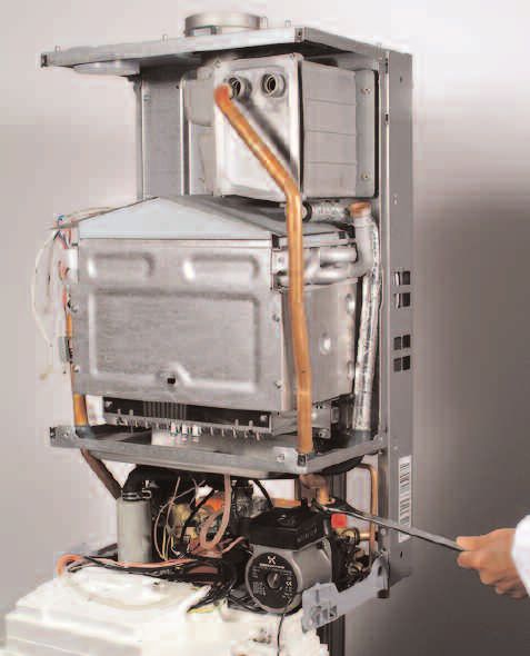
201 2.12 REMOVING THE FRONT PANEL
In order to access the inside of the boiler, it is necessary to unscrew
the fastening screws “A” of the control panel located on the lower
part of the panel itself.
The control panel moves downward and when pulled forward
rotates on two lateral hinges.
The panel stays in a horizontal position, which allows access to the
inner parts of the boiler.
A To dismantle the front casing panel it is necessary to:
1 - Remove the two screws “B”;
2 - Move the front casing panel up and lift forward.
2
2.13 ROOM THERMOSTAT CONNECTION
To connect a room thermostat, it is necessary to:
1. - Open the control panel as indicated in SECTION 2.12.
B 2.- Remove the screws “A” from the terminal block on the reverse
of the control panel.
3. - Insert the thermostat cable through the cable grommet and
fasten it by means of the cable-clamp provided.
4. - Connect the thermostat wires to the terminal block (Diagram
A).
5.- If a remote time clock is to be fitted, disconnect the integral
time clock from the P.C.B.
6. - Using a volt-free switching time clock, connect the switching
wires from the time clock following points 1-4 above (Diagram
3 B).
7. - If using an external time clock and room thermostat, these
must be connected in series as points 1-6 above (Diagram C).
Note: Only a low voltage room thermostat capable of volt
free switching must be used.
Factory fitted integral wiring must not be disturbed
A when wiring external controls.
A Ensure high voltage and low voltage circuits are
cabled separately to avoid induced voltage in the low
voltage circuits.
FIG. 2.21
212.14. FITTING THE DIGITAL CLOCK
The microGENUS HE boiler is supplied with a factory fitted
mechanical time clock. There is a digital clock available as an
optional extra (code: 706348).
To fit the digital clock it is necessary to proceed as follows:-
1. Remove the screws A (FIG. 2.22) and lower the control panel;
2. Open the control panel (see Section 2.12);
3. Remove the screws D1 to gain access to the mechanical time
clock (FIG. 2.25)
A
3. Unplug the electrical connection from the PCB D7 (FIG. 2.26)
FIG. 2.22 and unscrew the four screws (FIG. 2.26);
4. Connect the wires supplied with the replacement clock kit to the
digital time clock as shown in FIG. 2.27;
5. Reassemble in reverse order.
NOTE: THE MECHANICAL CLOCK HAS FOUR WIRES, THEREFORE THE
HARNESS WILL REQUIRE CHANGING ALSO.
A
A
FIG. 2.23
D1
D1
D6
D1
D1
FIG. 2.24 FIG. 2.26
DIGITAL MECHANICAL
D7
DIGITAL MECHANICAL
3 2 1 5 4 3 2 1
G B R G B R
FIG. 2.25
FIG. 2.27
222.15. SETTING THE MECHANICAL TIME CLOCK 1. General layout
The mechanical clock covers a 24 hour period. Each tappet
represents 15 minutes A (Fig. 2.29). An override switch is located
on the clock B (Fig 2.29).
E C
2. To set the time
To set the time of day, grasp the outer edge of the dial and turn
slowly clockwise until the correct time is lined up with the arrow C
(Fig. 2.29).
I
3 4
3 4
3. To Set the "On" and "Off" times
5
2
2
5
The clock uses a 24hours system. e.g. 8 = 8.00 am and
1
6
6
1
18 = 6.00 pm. "ON" periods are set by sliding all tappets between
the "ON" time and the "OFF" time to the outer edge of the
dial.The tappets remaining at the centre of the dial are the "OFF"
periods.
FIG. 2.28
4. For operation
Put the selector switch B to the symbol to control the central
heating by the clock. Put the switch B to «I» to select permanent
operation or to «0» to turn the central heating off permanently.
A
2 1 24
3 23
22
4
12
21
5
C
I
20
6
9
19
7
18
8
17
9
B
6
16
10
11 15
12 13 14
FIG. 2.29
2.16. SETTING THE DIGITALTIME CLOCK Operating the time switch
The steps marked with the symbol “ ” are necessary to carry out
a switching program.
Manual switch
Summer and Preparing for Operation
winter time
Reset setting Activate the “Res” switch (=RESET) to reset the time switch to
its default setting (activate using a pencil or similar pointed
instrument). Do this:
Enter Enter - every time you wish to “reset” the time switch
switching the hours
times
- to erase all switching times and the current time of day.
.
Prog
After approximately two seconds the following display appears:
h
Week-
days
“– – : – –”.
flash
m
Imput Enter Enter current time and weekday
time minutes
- Keep the “ ” key pressed down
Day During the summer time period press the +/- 1h key once.
Enter the hour using the “h” key
Enter the minutes using the “m” key
Enter Enter the day using the “Day” key
weekday/s
1 = “Monday”..............7 = Sunday
- Release the “ ” key.
23Changing the programmed switching times
Automatic Manual Continuous Press the “Prog” key repeatedly until the switching time you want to
Operation Operation Operation change is displayed. You can now enter the new data. See point
“Entering the switching times”.
= ON = ON = Continuously ON
= OFF = OFF = Continuously OFF Notes on storing switching times:
If you end your entry of the switching times by pressing the “Prog”
The switching If the current You can only key, then the switching time you have entered will be stored and the
times corres- switching mode is return to automatic
pond to the changed manually, mode from the next memory location displayed.
program the next switching continuously-ON
entered. time will be and continuously-
carried out auto- OFF switching In addition, a complete switching command is stored automatically
matically again modes by after around 90 seconds provided no other key is pressed. The time
according to the pressing the " "
entered switching key.
switch then enters the automatic operating mode and displays the
program. current time again.
Deleting individual switching times
Entering the switching times Press the “Prog” key repeatedly until the switching time you wish to
You have 20 memory Iocations available. Each switching time delete is shown in the display. Then set to “– –” using the “h” or “m”
takes up one memory location. key and keep the “ ” key pressed down for around 3 seconds. The
Keep pressing the “Prog” key until a free memory location is switching time is now erased and the current time is displayed.
shown in the display “– –:– –”.
Programme ON or OFF with the “ ” key: AM / PM time display
“ ”= OFF; “ ”= ON If you press the “+/-1h” and “h” keys at the same time, the time display
Enter the hour using “h” switches into the AM/PM mode.
Enter the minutes using “m”
If a switching command is to be carried out every day (1 2 3 4 5
6 7) then store using the “ ” key, otherwise select the day(s) it
is to be carried out by using the “Day” key.
When the day seIection is left bIank, the programmed switching
instruction operates at the same time every day
123456 = Monday – Saturday
12345 = Monday – Friday
67 =Saturday – Sunday
Selection of single days: 1 = Mon. .............. 2 =Tues.
Save the switching time with the “ ” key.
The time switch enters the automatic operating mode and
displays the current time of day.
Begin any further entry of a switching time with the “Prog”
switch. If your entry is incomplete, the segments not yet
selected will blink in the display. After programming is
completed, and you return the time clock to the current time
display with the “ ” key, the time clock will not activate any
switching instruction required for the current time. You may need
to manually select the desired switching state with the “ ”
key. Thereafter, as the unit encounters further switching
instructions in the memory in real time, it will correctly activate
all subsequent switching instructions.
Manual Override Switch “ ”
With the “ ” you can change the current setting at any time. The
switching program already entered is not altered.
Reading the programmed switching times
Pressing the “Prog” key displays the programmed switching times
until the first free memory location appears in the display “– – : – –”.
If you now press the “Prog” key once again, the number of free
memory Iocations will be displayed, e.g. “18”. If all memory locations
are occupied, the display “00” appears.
2425
FIG. 2.30
Wh
A16
Wh
Rd
Blk
Rd
Wh
Rd
Bl
1 2 3 4 5 6 7 8
M
CN205
A
ON
N
CN203
1 2 3 4 5 6
B
L
H
Blk
Blk
Rd
CN206
Gry
Gry
Gry
Blk
CN206
CN201
Blk
Gry
CN203
Gry
Pnk
Wh
Rd
CN205
5 6
CN200
O
I
Wh
Wh
Pnk
CN201
Pnk
CN300
Gry or Bl
FUSE
FUSE
Q
Blk
Blk
CN303
CN302
P
Blk CN303
CN302
Brn
CN304
Brn
Brn
Bl
Bl
Bl
Blk
ELECTRICAL/SYSTEM DIAGRAMS 2.17A - Dip Switches
B - Summer/Winter Switch - Central Heating Temperature
Regulation
C - Connector for Remote Control (Climate Manager)
D - Domestic Hot Water Temperature Regulation
E - Soft-light Regulation
F - Maximum Central Heating Temperature Regulation H
G - ON/OFF Selector
H - EEPROM
I - Time Clock Connector
L - Release Push Button
M - Economy/Comfort Selector
N - EASY Teleservice (optional) P.C.B. Section
O - Display P.C.B. Connector
P - Transformer
Q- Modem Connection (optional - EASY Teleservice)
A01 - Circulation Pump
A02 - Fan
A03 - Spark Generator Power Supply ATTENTION
A04 - Gas Valve Power Supply IN CASE OF R E P L AC E M E N T OF THE PCB
A05 - Motorised Valve DISCONNECT THE EEPROM (LEAVE IT ATTACHED
A07 - Flame Sensor TO THE CONTROL PANEL) AND RECONNECT TO THE
A08 - Central Heating Flow NTC
NEW PCB.
A09 - Domestic Hot Water NTC
A10 - Domestic Hot Water Flow Switch
A11 - Low Water Pressure Switch
A12 - Modulator
A13 - Air Pressure Switch
A14 - Overheat Thermostat
6
A15 - External Timer/Room Thermostat
A16 - Condensate Sensor
A17 - Fume Sensor
5
4
COLOURS:
3
Gy - Grey
Wh - White
2
Rd - Red
Br - Brown
1
Bl - Blue
Bk - Black
Pk - Pink
A
A - Dip Switch:
B
1- Do Not Use (jumper is factory set in position B)
2- Anti-Cycling Device Adjustment for Heating
Position A = 0 mins Position B = 2 mins
3- Do Not Use (jumper is factory set in position B)
4- Do Not Use (jumper is factory set in position B)
5- Fan over-run selector (after D.H.W. is drawn)
Position A = OFF Position B = ON
6- Do Not Use (jumper is factory set in position A)
262.18 WATER CIRCUIT DIAGRAM
FIG. 2.28
24
23
1
2 22
3
21
4
5
6
7
20
8 19
9 18
17
10
A B C D E
11 12 13 14 15 16 SI016C
LEGEND: A. Central Heating Flow
B. Domestic Hot Water Outlet
1. Fan C. Gas Inlet
2. Heat Exchanger D. Domestic Cold Water Inlet
3. Overheat Thermostat E. Central Heating Return
4. Central Heating Flow NTC
5. Burner
6. Detection Electrode
7. Ignition Electrodes
8. Diverter Valve
9. Low Water Pressure Switch
10. Drain Valve
11. Domestic Hot Water Temperature NTC
12. Secondary Heat Exchanger
13. Gas Valve
14. D.H.W. Flow Switch
15. D.H.W. Inlet Filter
16. Automatic By-pass
17. Safety Valve
18. Pressure Gauge
19. Circulation Pump with Automatic Air Release Valve
20. Condensate Trap
21. Expansion Vessel
22. Condensate Sensor
23. Latent Heat Collector
24. Air Pressure Switch
273. COMMISSIONING
3.1 INITIAL PREPARATION MTS (GB) Limited support the initiative. In Sections 11
and 12 of this manual you will find the commissioning
checklist (page 78) and the service interval record (Page 79), It
is important the commissioning checklist is completed
in the presence of your customer, they are shown how to use it,
and it is signed by them. Please instruct your customer that they
must have this manual with them whenever they contact a
service engineer or us.
Preliminary electrical system checks to ensure electrical safety
must be carried out by a competent person i.e. polarity, earth
continuity, resistance to earth and short circuit.
FILLING THE HEATING SYSTEM:
Lower the control panel and remove the case panels (see
SECTION 2.12 for further information).
Open the central heating flow and return cocks supplied with the
connection kit.
Unscrew the cap on the automatic air release valve one full turn
and leave open permanently.
Close all air release valves on the central heating system.
Gradually open valve(s) at the filling point (filling-loop) connection
to the central heating system until water is heard to flow, do not
open fully.
Open each air release tap starting with the lowest point and close
them only when clear water, free of air, is visible.
Purge the air from the pump by unscrewing the pump plug
anticlockwise, also manually rotate the pump shaft in the
direction indicated by the pump label to ensure the pump is
free.
Refit the pump plug.
Continue filling the system until at least 1.5 bar registers on the
pressure gauge.
Inspect the system for water soundness and remedy any leaks
discovered.
FILLING OF THE D.H.W. SYSTEM:
Close all hot water draw-off taps.
Open the cold water inlet cock supplied with the connection kit.
Open slowly each draw-off tap and close them only when clear
water, free of bubbles, is visible.
GAS SUPPLY:
Inspect the entire installation including the gas meter, test for
tightness and purge the supply as described in BS 6891:1988.
Open the gas cock (supplied with the connection kit) to the
appliance and check the gas connections on the appliance for
leaks.
WATER TREATMENT
The detailed recommendations for water treatment are given in
BS 7593:1992 (Treatment of water in domestic hot water central
heating systems); the following notes are given for general
guidance:
- If the boiler is installed in an existing system, any unsuitable
additives must be removed;
- Under no circumstances should the boiler be fired before the
system has been thoroughly flushed; the flushing procedure
must be in line with BS7593:1992.
Firstly fill the central heating system and boiler with the power off
and flush through cold, fill the central heating system again, add
a flushing detergent, we highly recommend the use of a flushing
detergent appropriate for the metals used in the aluminium alloy
circuit. These include (Fernox Superfloc, BetzDearborn Sentinel
X300 or X400), whose function is to dissolve any foreign matter
that may be in the system, and run the boiler on central heating
until it reaches its operating temperature, flush the system as
instructed by the manufacturer of the flushing detergent and refill
the system with a suitable corrosion inhibitor such as Fernox
28Copal MB-1, or BetzDeaborn Sentinel X100 is recommended.
NOTE: FAILURE TO CARRY OUT THE FLUSHING PROCEDURE WILL RESULT IN
THE WARRANTY BECOMING VOID.
In hard water areas or where large quantities of water are in the
system the treatment of the water to prevent premature scaling
of the main heat exchanger is necessary.
The formation of scale strongly compromises the efficiency of the
thermic exchange because small areas of scale cause a high
increase of the temperature of the metallic walls and therefore
add to the thermal stress of the heat exchanger.
Demineralised water is more aggressive so in this situation it is
necessary to treat the water with an appropriate corrosion
inhibitor.
- Any treatment of water by additives in the system for frost
protection or for corrosion inhibition has to be absolutely suitable
for all the metals used in the circuit including the aluminium
alloys.
- If anti-freeze substances are to be used in the system, check
carefully that they are compatible with the aluminium.
In particular, DO NOT USE ordinary ETHYLENE GLYCOL, since
it is corrosive in relation to aluminium and its alloy, as well as
being toxic.
MTS suggests the use of suitable anti-freeze products such as
Fernox ALPHI 11, which will prevent rust and incrustation taking
place.
Periodically check the pH of the water/anti-freeze mixture of the
boiler circuit and replace it when the amount measured is out of
the range stipulated by the manufacturer ( 7 < pH < 8).
DO NOT MIX DIFFERENT TYPES OF ANTI-FREEZE
- In under-floor systems, the use of plastic pipes without protection
against penetration of oxygen through the walls can cause
corrosion of the system’s metal parts (metal piping, boiler, etc),
through the formation of oxides and bacterial agents.
To prevent this problem, it is necessary to use pipes with an
“oxygen-proof barrier”, in accordance with standards DIN
4726/4729. If pipes of this kind are not used, keep the
system separate by installing heat exchangers of those with
a specific system water treatment.
IMPORTANT
Failure to carry out the water treatment procedure will
invalidate the appliance warranty
When the installation and filling are completed, flush the system
while cold, refill, turn on the Central Heating system (SECTION 3.2)
and run it until the temperature has reached the boiler operating
temperature. The system must then be immediately flushed through.
The flushing procedure must be in line with BS 7593:1992 code of
practice for treatment of water in domestic hot water central heating
systems.
During this operation, we highly recommend the use of a central
heating flushing detergent (Fernox Superfloc or equivalent), whose
function is to dissolve any foreign matter that may be in the system.
Substances different from these could create serious problems
to the pump or other components.
The use of an inhibitor in the system such as Fernox MB-1 or
equivalent is strongly recommended to prevent corrosion (sludge)
damaging the boiler and system.
Failure to carry out this procedure may invalidate the appliance
warranty.
29You can also read