Methanol as marine fuel: Environmental benefits, technology readiness, and economic feasibility - USE OF METHANOL AS FUEL - IMO International ...
←
→
Page content transcription
If your browser does not render page correctly, please read the page content below
USE OF METHANOL AS FUEL

Methanol as marine fuel:
Environmental benefits,
technology readiness, and
economic feasibility
International Maritime Organization (IMO)

Report No.: 2015-1197, Rev. 2
Document No.:
Date: 20.01.2016

Project name: Use of Methanol as fuel DNV GL Maritime
Report title: Methanol as marine fuel: Environmental benefits, Environmental advisory
 technology readiness, and economic feasibility
Customer: International Maritime Organization (IMO)
Contact person: Edmund Hughes
Date of issue: 20.01.2016
Project No.: PP142879
Organisation unit: Maritime advisory, Environmental advisory
Report No.: 2015-1197, Rev. 2
Document No.:
Applicable contract(s) governing the provision of this Report:

DNV GL – Report No. 2015-1197, Rev. 2 – www.dnvgl.com Page i
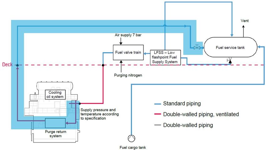
Table of contents
ABBREVIATIONS .......................................................................................................................... 1

1 EXECUTIVE SUMMARY ..................................................................................................... 2

2 INTRODUCTION .............................................................................................................. 3
2.1 Methanol in industry 3

3 THE CURRENT ENVIRONMENTAL REGULATORY REGIME ....................................................... 5
3.1 IMO regulations 5
3.2 Other regional requirements 7

4 IDENTIFYING THE ENVIRONMENTAL BENEFITS OF METHANOL ............................................. 8
4.1 Methanol fuel production 9
4.2 Combustion of methanol on board ships 14
4.3 Life cycle emissions of conventional fuels 15
4.4 Comparing life cycle emissions of methanol to conventional fuels 17

5 IDENTIFICATION OF TECHNOLOGY READINESS ................................................................ 20
5.1 Introduction 20
5.2 System breakdown 20
5.3 Summary of technology readiness 34
5.4 Costs of Methanol as fuel 37
5.5 Encouraging the use of methanol 44

6 CONCLUSIONS ............................................................................................................. 45

7 REFERENCES ................................................................................................................ 47

DNV GL – Report No. 2015-1197, Rev. 2 – www.dnvgl.com Page ii
ABBREVIATIONS

ECA Emission Control Area
 (SECA Sulphur Emission Control Area)

FMECA Failure mode, effect and criticality analysis

GHG Green House Gas

IMO International Maritime Organization

IR Infra-Red

HAZID Hazard identification

HFO Heavy fuel oil

LFL Low Flashpoint Liquid

LCA Life cycle assessment

MGO Marine gas oil

NOx Nitrogen oxides

SOx Sulphur oxides

DNV GL – Report No. 2015-1197, Rev. 2 – www.dnvgl.com Page 1
1 EXECUTIVE SUMMARY
The purpose of the study is to determine the environmental benefits of using methanol as fuel on ships
with regards to emissions of greenhouse gases (GHGs), NOx and SOx. The potential environmental gains
are seen in the context of current and future environmental regulations for methanol in maritime use,
and in context of the costs of adaption and technical readiness.

The environmental assessment of methanol used as ship fuel shows that, for a life-cycle perspective,
methanol produced with natural gas has higher GHG emissions than conventional fuels. However,
methanol produced with biomass has the potential to save significant emissions, provided that the
electricity used in the process is relatively clean. The life-cycle NOx emissions from methanol are
approximately 45 % of those from conventional fuels per unit energy and the life-cycle SOx emissions of
methanol are approcimately 8 % of those from conventional fuels per unit energy. In the case of both
NOx and SOx, the emissions reductions are due to the fact that methanol results in lower emissions
during the combustion phase.

The assessment of technology readiness for methanol as fuel shows that the methanol fuel system,
consists mostly of well-known components, and that the individual components are of a mature
technology and have been used in the maritime industry. The new application is the connection of all
these components along the methanol flow and how they interact with each other. The assessment also
shows that additional safety barriers are needed in every part of the methanol fuel system. From a
technical aspect this is very much achievable for ship-owners, both for newbuild and a retrofit systems.

From a cost perspective, methanol as fuel only shows potential within certain circumstances. These are
mainly that MGO prices are high and that the time spent in ECAs for the vessel is a large portion of the
total sailing time.

DNV GL – Report No. 2015-1197, Rev. 2 – www.dnvgl.com Page 2
2 INTRODUCTION This study was carried out using funds provided to IMO by Transport Canada for analytical studies and other activities pertaining to the control of air related emissions from ships. The purpose of the study is to determine the environmental benefits of using methanol as fuel on ships with regards to emissions of greenhouse gases (GHGs), NOx and SOx. The potential environmental gains will be seen in the context of current and future environmental regulations for methanol in maritime use, and in context of costs of adaption and technical readiness. Methanol has been given attention as a low carbon alternative fuel because it can be synthesized from a number of feedstocks. Beyond the possibility of producing methanol with renewable resources, methanol is an environmentally interesting fuel for ships due to its low sulphur, NOx, and particulate emissions. The low sulphur emissions make methanol an alternative for satisfying the IMO sulphur emission control area (SECA) requirements for SOx. The Swedish ferry and freight operator Stena Line has successfully retrofitted one of its vessels for using methanol as a solution to low sulfur fuel requirements. This is the world’s first and only vessel running on methanol, at the time of writing. Additionally, a number of chemical carriers are also being designed to be able to run on methanol, so that they can use their own methanol cargo as fuel in SECAs. This analysis will address the question: what are the environmental benefits of methanol and what makes a shipowner choose methanol over other traditional and alternative fuels? 2.1 Methanol in industry Methanol, also known as methyl alcohol or wood alcohol, is a chemical with the formula CH 3OH. Most methanol produced today is used in the petrochemical industry, employing methanol as a feedstock to produce other chemicals, in particular formaldehyde and acetic acid /1/. Today methanol is generally produced using natural gas as a feedstock. Methanol has piqued interest as an alternative, low-carbon fuel because it is also possible to produce with renewable feedstocks such as municipal waste, industrial waste, biomass, and carbon dioxide /2/. Methanol is only employed as a transportation fuel on a significant basis for cars in China, where it is inexpensive and readily available. Methanol in China is produced cheaply from coal, which causes a highly negative GHG impact. Figure 2-1 Symbolic representation of methanol molecule, CH3OH DNV GL – Report No. 2015-1197, Rev. 2 – www.dnvgl.com Page 3
The use of methanol in the maritime industry is currently, limited. As mentioned previously, Stena Line
has retrofitted a ro-ro passenger vessel for methanol use. There are currently 7 chemical tankers under
construction which will ship methanol and run on their cargo.

DNV GL – Report No. 2015-1197, Rev. 2 – www.dnvgl.com Page 4
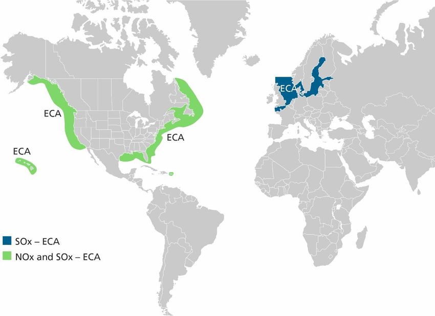
3 THE CURRENT ENVIRONMENTAL REGULATORY REGIME The current regulations in place which can work to encourage the uptake of methanol for shipowners are related to restrictions on sulphur oxide (SOx), the most important being SOx restrictions imposed by IMO in emission control areas(ECAs) and in EU by the sulphur Directive 1999/32/EC (as amended by Directive 2012/33/EU). 3.1 IMO regulations The main international shipping convention regulating emissions to air from ships is the IMO International Convention on the Prevention of Pollution from Ships (referred to as MARPOL). MARPOL Annex VI establishes limits for SOx and NOx globally and in ECAs. The global limit of sulphur content in fuel will be reduced from 3.5% to 0.5% (m/m) in 2020 or 2025. The date of implementation will be decided by 2018. The use of scrubbers will be accepted in this regime. Ships sailing in SOx-ECAs (SECAs) are required to run on fuel with a sulphur content of 0.1 % (m/m) or less after January 2015, alternatively using an equivalent method such as exhaust gas cleaning, or alternative fuels with low sulphur content. There are two established SECAs: the Northern European SECA, and the North American and US Caribbean ECA. These are shown in Figure 3-1. There is a possibility for new ECAs in Mexico and Turkey (the Bosporus Straits and Sea of Marmara). Equivalent purification of exhaust gas from HFO by scrubbers is accepted (except in California where it is banned by state regulation, but this ban is expected to be lifted in 2015). DNV GL – Report No. 2015-1197, Rev. 2 – www.dnvgl.com Page 5
Figure 3-1 Current established emission control areas MARPOL Annex VI also establishes limits for NOx emissions from marine diesel engines of more than 130 kW output, dependent on engine mean rotational speed and the ship construction date (keel-laid date of the ship). The keel-laid date determines if a vessel is beholden to Tier I, II, or III: Tier I – Ships keel laid from January 1st, 2000 to January 1st 2011 Tier II – Ships keel laid on or after January 1st 2011 Tier II – Ships keel laid after January 1st, 2016 operating in the North American Emission Control Area or the United States Caribbean Sea Emission Control Area. The relevant NOx emissions for each tier level are shown in Figure 3-2. Figure 3-2 Allowable NOx emission from marine engines according to tier Currently, the only established NOx ECAs (NECA) are the North American ECA and the United States Carribean sea ECA. The keel-laid date after which vessels must adhere to Tier-III in future NECAs which can come into effect, cannot be earlier than the date of adoption of the NECA. Beyond requirements for SOx and NOx pollution prevention, MARPOL Annex VI mandates the energy efficiency design index (EEDI) for new ships, as well as a Ship Energy Efficiency Management Plan (SEEMP) for all ships. The EEDI establishes a mileage standard for ships where the environmental burden of running the ship (CO2 emissions) is measured against the benefit for society (transport work). 2 = The design EEDI has been established for selected ship types and sizes above 400 GT. Ships will be required to satisfy the required EEDI value which is valid for the ship type, size, and keel date. The design EEDIs are intended to establish energy efficiency standards to which ships must adhere at the DNV GL – Report No. 2015-1197, Rev. 2 – www.dnvgl.com Page 6
design stage. The later the keel-lay date, the more stringent the standard mandated by IMO. The EEDI
requirements are in force but will evolve as part of an agreed review process.

Biofuels (such as methanol produced from biomass) are not considered in the existing EEDI regulation.
The EEDI calculation guidelines /3/ establish a carbon factor for methanol, regardless of whether or not
it is produced boimass. However, the flag state may allow any fitting alternatives fuel oils, or compliance
methods used as an alternative to the requirements of the EEDI if the alternative is at least effective in
terms of emissions reductions as that required by the EEDI /4/. This means that a flag state can allow
for biofuels such as methanol created with biomass to satisfy the EEDI requirements as an alternative to
energy efficiency requirements stipulated in the EEDI. Possibly setting a different carbon factor for
biofuels.

In such a case, vessels running on biofuels must document that their motor is built to run on biofuels
and that biofuels are the primary fuel. Exactly how this is to be documented is not yet established, so it
will be up to the flag state to determine which criteria will constitute a motor built and running on
biofuels as the primary fuel and therefore to what extent bio-methanol will be advantageous in achieving
compliance with EEDI, compared to other fuels.

3.2 Other regional requirements
Other than the MARPOL requirements, EU’s Sulphur Directive limits sulphur content in fuel to 0.5 % in
EU waters (non-ECA) beginning January 2020. Equivalent purification of exhaust gas from HFO by
scrubbers is accepted, though scrubber discharge water is not accepted in certain coastal waters, ports
and river estuaries

Article 4b of the Council Directive 1999/32/EC as amended by Directive 2005/33/EC stipulates that ships
at berth in European Union ports must use marine fuels with a maximum sulphur content of 0.1% (m/m)
at all times.

The Directive also requires that all ships at berth in EU ports after 2010 must use marine fuels with a
maximum sulphur content of 0.1% (m/m). The Directive also mandates that all passenger vessels on
scheduled routes must burn fuel at equal or less than 1.5% in all EU waters. (Except in SECAs where
stricter restrictions apply.)

There are currently no EU directives specifically targeting NOx emissions from ships.

ECA-like requirements are also likely forthcoming in parts of Chinese waters /5/. The Chinese Ministry of
Transport has indicated that it will establish emission control areas from 1 January 2016 in the pearl
river Delta, Yangtze River Delta and Bohai Rim. Vessels at berth inside the areas will be strongly advised
to use bunker fuels with a sulphur content of less than 0.5% m/m sulphur.

DNV GL – Report No. 2015-1197, Rev. 2 – www.dnvgl.com Page 7
4 IDENTIFYING THE ENVIRONMENTAL BENEFITS OF METHANOL In order to identify the environmental benefits of using methanol as marine fuel, the total life cycle emissions of methanol propulsion on ships are compared to conventional fuels – MGO and HFO. The life cycle emissions of SOx, NOx and greenhouse gases (GHGs: CO2, CH4, and N2O) are identified for the production and emission phases of methanol production. The system boundaries for the life-cycle emissions are well-to-propeller, meaning that the emissions of extracting and refining raw fossil fuels are taken into account. The entire life-cycle can be divided in two main phases: well-to-tank (the total emissions of extracting raw materials, producing, and transporting the fuel) and tank-to-propeller (the emissions from combustion and potential leakage). The emissions of CO2 and SOx from the combustion phase are dependent on the carbon and sulphur content of the fuel in question. The emissions of CH4, N2O, and NOx are based on temperature and combustion conditions. These values will also vary with engine load and rpm, but average emissions factors in g/MJ fuel are used in this study. All life cycle emissions are normalized per MJ content of fuel. Emissions of CH4 and N2O have different contributions to global warming. These emissions are therefore normalized to g CO2-equivalents, so that the total GHG emissions can be summed and the life-cycle GHG emissions from each fuel type can be compared. The CH4 and N2O emissions are converted to CO2 equivalents using a 100 years’ time horizon. This means that the CH4 and N2O emissions are normalized according to their effect on global warming of a 100-year time scale. Normalization factors are given in Table 4-1. Table 4-1 Global warming potential of CH4 and N2O /6/ Global warming potential for 100 year time horizon (g CO2- Emissions equivalents/g emissions)1 CO2 1 CH4 25 N2O 298 CH4 and N2O are not emitted in large quantities from combustion methanol or conventional marine fuels, but they are taken into account because they are emitted in the production process and their inclusion is important to for the completedness of any life-cycle GHG inventory. SOx and NOx emissions are important in a maritime context primary because of their harmful effects on human health, land-based infrastructure and natural habitats. Their emissions near ports or where humans are present is where they do most damage, but on a regional level they also contribute to acid rain creation and potentially local acidification of the marine environment. Their life-cycle emissions are therefore quantified here. Particulate emissions are important from a human health perspective, with black-carbon also seeing attention as a short-lived climate change forcer and a potential ice-melt accellerant. However, such emissions are outside of the scope of this study. Additionally, methanol combustion does emit formaldehyde, which has a human health effect, but this is outside of the scope of this study. Other issues outside of scope include the possible cooling effects of SOx and aerosols in the atmosphere, the formaldehyde emissions from methanol and the uncertainty of NOx’s impact on climate chemistry. 1 The IPCC has made an update to global warming potential for CH4 and N2O but values from the 2007 IPCC report are used here to ease comparison with other life cycle assessments of marine fuels. DNV GL – Report No. 2015-1197, Rev. 2 – www.dnvgl.com Page 8
4.1 Methanol fuel production 4.1.1 Methanol production with natural gas Currently, the methanol used on board the Stena Germanica – the only current vessel employing methanol in the world– is produced by natural gas synthesis, as is most of the methanol produced in the world today. The methanol Stena purchases can theoretically come from any number of production sites, with various natural gas sources as the feedstock. It is assumed here that the majority of methanol used by Stena is produced in Europe with natural gas produced from Norwegian fields. Methanol production from natural gas entails a combination of steam reforming and partial oxidation, with up to about 70 % energy efficiency /7/. The main emissions occurring during the production process are the emissions from combustion of natural gas. The process of producing methanol is highly exothermic, and the excess heat is used to generate electricity in a plant /8/. It can therefore be assumed that there are no extra energy inputs to the production process at the plant and that only negligible emissions occur beyond the natural gas combustion. Further up the value chain, emissions will also occur from the extraction, and transport of natural gas so that it can be used in the methanol plant. The emission estimates from natural gas extraction used in this study are based on natural gas extraction from Norwegian fields, and include emissions from transporting the gas to mainland Europe. Additionally, it is assumed that the emissions from transporting and bunkering methanol are the same as those for MGO and HFO.The difference in energy density of methanol is assumed to have a neglible impact on emissions from transport, which are small compared to other parts of the life-cycle. The life cycle of methanol production with natural gas is shown in Figure 4-1. Figure 4-1 Map of life cycle phases of methanol production and use as fuel in ships The emissions from extracting the natural gas and transporting it to the methanol production site are based on the European Life Cycle Database (ELCD) /9/. These values are based on Norwegian natural DNV GL – Report No. 2015-1197, Rev. 2 – www.dnvgl.com Page 9
gas extraction, and gas being sent via pipeline to a production site, totalling at 2.4 gCO2eq/MJ natural gas. Different fields will have different energy requirements for extracting gas, and different efficiencies for gas processing and transportation. Although it is difficult to compare different life cycle assessment (LCA) studies because the system boundaries can vary, Figure 4-2 shows the GHG emissions from gas extraction in various locations, in order to show the variation in emissions from natural gas extraction /10/. The results are from a study performed by the U.S. Department of Energy, with three scenarios: LNG produced in the US and shipped to Rotterdam, LNG produced in Algeria and shipped to Rotterdam, and natural gas produced in Russia and sent via pipeline to Rotterdam. The results of the three scenarios are shown with the emissions values of Norwegian natural gas production taken from the ELCD database. GHG emissions of natural gas extraction 9 8 7 g CO2 eq/MJ 6 5 4 3 2 1 0 US LNG Algeria LNG Russian NG Norwegian NG Figure 4-2 GHG emissions of natural gas extraction Figure 4-2 shows the emissions from extraction only. LNG will have additional emissions from liquefaction and other processing. Several studies choose to use emissions of Norwegian natural gas extraction to calculate the life-cycle values of fuel production when production occurs in Europe (Strømman et al. 2006 /11/, Smyrnolf et al. 2014 /12/). Despite the uncertainty in the emission of gas extraction and transportation, the well-to-tank GHG emissions from methanol produced with natural gas are dominated by the emissions from natural gas combustion occuring at the methanol plant. The well-to-tank emissions of methanol production with natural gas are shown in Figure 4-3. DNV GL – Report No. 2015-1197, Rev. 2 – www.dnvgl.com Page 10
Well-to-tank GHG emissions from methanol produced with natural gas 30 25 20 Methanol transportation g CO2 eq/MJ 15 Methanol production 10 Gas extraction & transportation 5 0 Methanol (NG) Figure 4-3 Well-to-tank emissions from methanol produced with natural gas The impact of methanol transportation is so small as to be barely visible in the figure. DNV GL – Report No. 2015-1197, Rev. 2 – www.dnvgl.com Page 11
4.1.2 Methanol production with biomass Although today’s limited application of methanol as fuel for ships is mostly synthesized from natural gas, it is important to consider the life-cycle emissions from methanol produced with biomass. It is the eventual transition to bio-methanol that is the environmental motivation for using methanol on ships as additional reason for sustainabilty beyond no sulphur content. Methanol can be produced with biomass such as residues from forestry. Biomass materials are used to make black liquor in pulp and paper mills, where it is normally combusted to generate energy and recover chemicals. However, black liquor can also be gasified in an oxygen-rich atmosphere and methanol produced from the resulting syngas, without compromising the recovery of the chemicals. This process may be integrated into the pulp and paper mill process with access to excess biomass /13/. Such a methanol production process is the grounds for the life-cycle GHG estimates of bio-methanol below. In such a process, the emissions from methanol production will come from the emissions generated elsewhere to create electricity needed. The source of electricity is an important factor for the total GHG emissions of methanol created with biomass, because the emissions from electricity generation can vary according to the raw energy source. The amount of renewable resources used to generate electricity varies from country to country. Figure 4-4 illustrates the upstream CO2 emissions of the electricity mixes for various countries. CO2 emissions of various electricity mixes 70 g CO2 eq/ MJ electricity 60 50 40 30 20 10 0 Finland Sweden Russia Figure 4-4 CO2 emissions for electricity mixes of various countries Sweden, Finland, and Russia are shown here as examples due to their large biomass availability. Besides the emissions from electricity, additional emissions may arise when the waste biomass from a mill is not sufficient to fulfil the biomass needs of methanol production, and this deficit is filled by burning fossil fuels to create enough black liquor. Additionally, transportation of biomass and methanol will generate emissions. The life cycle GHG emissions of bio-methanol production are modelled in the DNV GL study the Fuel Trilemma /13/, based on electricity need of 2.1 MWh/tonne of methanol. GHG emissions from electricity mixes are taken from the IEA. In order to model the emissions in the case of a plant with a biomass deficit, a 15% additional biomass demand is assumed to be filled by burning residual fuel oil. Figure 4-5 shows the results of life cycle emissions from biomass methanol production, using the Finland energy mix, and the Russian energy mix. Results for a plant with a biomass deficit which must be filled using residual fuel oil are also shown. DNV GL – Report No. 2015-1197, Rev. 2 – www.dnvgl.com Page 12
Well-to-tank GHG emissions of methanol produced from biomass 80 70 60 g CO2 eq/MJ 50 Biomass deficit 40 Transport methanol 30 Transport wood 20 Electricity 10 0 Finnish electricity Russian electricity Finnish electricity mix mix mix and biomass deficit Figure 4-5 GHG emissions of methanol produced from biomass Direct GHG emissions generated from the combustion of synthesis gas from biomass and the combustion of methanol from bio-methanol are considered climate neutral, and they are therefore not included in the life-cycle emissions. Bio-methanol produced with a clean electricity mix has therefore a potential to have low GHG emissions. Comparing Figure 4-3 to Figure 4-5 shows that the well-to-tank emissions of producing methanol with biomass are not much lower than with natural gas. However, the combustion of biomethanol and methanol produced with natural gas will result in fewer GHG emissions. (This will be discussed in greater detail in section 4.4.) DNV GL – Report No. 2015-1197, Rev. 2 – www.dnvgl.com Page 13
4.2 Combustion of methanol on board ships The actual CO2 emissions from combustion of methanol are based on the carbon content per MJ fuel. The carbon content can vary slightly according to the purity of fuel, however purity of the product is well controlled in the production process. This study uses as a basis that methanol combustion emits 69 gCO 2 per MJ methanol combusted /9/. CO2 from combusted bio-methanol is considered climate neutral2, and is therefore not considered a GHG gas. This is because it is assumed that CO2 emitted from biomass-based fuel is removed from the atmosphere once new biomass grows to replace the biomass used to produce the fuel. CH4 and N2O emissions from methanol are assumed to be negligible /12/. SOx emissions are based on sulphur content of methanol, which is negligible /12/. There have been few tests measuring the NOx emissions from methanol combusted in marine engines. Wärtsilä has tested NOx emissions from methanol against those from HFO in two engine models: pre- tests on the Wärtsilä Vasa 32, and full tests on the Sulzer Z40S-MD /14/. Their results show that NOx emissions were approximately 40% of emissions from HFO from the same engines at similar load. However, the NOx emissions were not as low as Tier III levels. It is therefore assumed that NOx emissions during combustion are reduced by approximately 60 % when running on methanol compared to HFO. MAN Diesel has performed tests with a methanol in marine diesels resulting in a 30% reduction in NOx emissions compared to diesel /15/. (Although the results of tests from Wärtsila /14/ and MAN /15/ differ, both indicate a significant decrease in NOx reduction when using methanol. Additionally, NOx emissions are dependent on combustion condistion, meaning that any parameter indicating NOx emissions per MJ fuel will contain some uncertainty.) The Wärtsilä tests also indicated that the fuel efficiency is the same or better when running on methanol. Stena’s experience indicates that they have better fuel efficiency in the order of 1-2% when running on methanol, although they have not performed tests to documents the change in efficiency. It is therefore assumed that the energy efficiency in marine engines remains unchanged when running on methanol. There is increased lubrication oil consumption when running on methanol, but this was considered negligible. The following combustion factors for methanol are employed. All factors depend on engine type to a certain extent. Table 4-2 Emissions factors for methanol combustion in marine engines Compound Emissions (g/MJ methanol) Source CO2 69 /12/ CH4 0 /12/ N2O 0 /12/ NOx 0.4 /14/ SOx 0 /12/ 2 Although CO2 emissions from biofuels, including bio-methanol, are considered to be climate neutral from a life cycle assessment perspective, they are not necessarily considered climate neutral when calculating the CO 2 emissions of methanol propulsion for the EEDI regulation (see .1). section 3 DNV GL – Report No. 2015-1197, Rev. 2 – www.dnvgl.com Page 14
4.3 Life cycle emissions of conventional fuels The life cycle emissions of conventional fuels, HFO and MGO, are based on well-to-tank: extraction and transport of raw materials (crude oil), refining, bunkering and storage of the fuel, and tank-to-propeller: combustion on board a vessel. The emissions from each phase are normalized per MJ fuel. Figure 4-6 Map of life cycle phases of HFO and MGO production and use in ships Values for relevant emissions from the well-to-tank part of the life cycle are based on the ELCD Core database /16//17/. This database includes environmental inputs and emissions for the necessary processes used to make HFO and MGO. The resulting values are representative for HFO and MGO produced in Europe /9/. Well-to-tank GHG emissions of conventional fuels 9.8 9.6 9.4 9.2 g CO2 eq/MJ 9.0 8.8 8.6 8.4 8.2 8.0 7.8 HFO MGO Figure 4-7 Well-to-tank emissions of HFO and MGO DNV GL – Report No. 2015-1197, Rev. 2 – www.dnvgl.com Page 15
The higher well-to-tank GHG emissions of MGO compared to HFO are due to the emissions from refining MGO. Table 4-3 shows the emissions factors from MGO and HFO when combusted in marine engines. CO 2 and SOx factors are based on carbon and sulphur content of fuel. SOx HFO and MGO factors are based on 1 % sulphur and 0.1 % sulphur respectively. The emissions of NOx also tend to differ according to MGO and HFO because MGO and HFO are run on different types of ships with different engine configurations. Slow-speed two stroke engines have higher NOx emissions due to longer times at higher temperatures and pressures because of their lower engine revolutions. The same emission NOx factors are therefore used in this study for MGO and HFO. Emission factors are based on emissions from ro-ro vessels. Table 4-3 Emissions factors for MGO and HFO combustion in marine engines /9/ Compound MGO emissions (g/MJ MGO) HFO emissions (g/MJ HFO) CO2 75 77 CH4 0 0 N2O 0 0 NOx 1 1 SOx 0.04 0.5 DNV GL – Report No. 2015-1197, Rev. 2 – www.dnvgl.com Page 16
4.4 Comparing life cycle emissions of methanol to conventional fuels 4.4.1 Greenhouse gas emissions Figure 4-8 shows the breakdown of GHG emissions from each life cycle phase of methanol production with natural gas. Life cycle GHG emissions from methanol produced with natural gas 120 100 Combustion g CO2 eq/MJ 80 Methanol transportation 60 Methanol production 40 Gas extraction & 20 transportation 0 Methanol (NG) Figure 4-8 Breakdown of GHG emissions according to life cycle phase from methanol produced with natural gas The life-cycle emissions from methanol production with natural gas are dominated by emissions from methanol production and combustion in marine engines. Since emissions from methanol combustion and methanol production at the plant are based on the chemical composition of natural gas and methanol respectively, there is little variation regarding these emissions. The emissions from extraction and transport of natural gas can vary significantly according to where the natural gas is produced. However, these emissions are small compared to those from combustion and production. DNV GL – Report No. 2015-1197, Rev. 2 – www.dnvgl.com Page 17
Life cycle GHG emissions for methanol and conventional 100 fuels 90 Tank-to- propeller 80 GHG emissions (g CO2 eq/MJ) Well-to- 70 tank 60 50 40 30 20 10 0 HFO MGO Methanol (NG) Methanol (biomass, Methanol (biomass, Finnish el. mix) Russian el. mix) Figure 4-9 Life cycle emissions for methanol produced using natural gas and biomass, compared to conventional fuels Figure 4-9 shows that emissions from the well-to-tank phase of methanol produced with natural gas are slightly higher than corresponding emissions from MGO and HFO. For comparison, the life cycle emissions of LNG from well-to-propeller are found to be from 72-90 g CO2 eq / MJ, meaning that the life-cycle GHG emissions of LNG are in the order of magnitude of conventional fuels. Provided that biomass is produced using a relatively clean electricity mix, the life-cycle GHG emissions of methanol production are less than half of conventional fuels. The environmental benefits of methanol are highly dependent on the raw materials used to make it. Even bio-methanol is not necessarily much improved over MGO if it is made with an electricity mix that does not have a high share of renewables. DNV GL – Report No. 2015-1197, Rev. 2 – www.dnvgl.com Page 18
4.4.2 Life-cycle NOx and SOx emissions The life cycle emissions of SOx and NOx have also been calculated based on the ELCD database /9/, and information in Table 4-2 and Table 4-3. The emissions of SOx and NOx from the well-to-tank production of bio-methanol are based on values for methanol produced from biomass via black liquor from (Brynolf, Fridell, & Andersson, 2014) /9/. Life-cycle NOx emissions of methanol compared to conventional fuels 1.2 1.0 0.8 0.6 Tank-to-propeller 0.4 Well-to-tank 0.2 0.0 HFO MGO Methanol (NG) Methanol biomass Figure 4-10 Life cycle emissions of NOx from marine fuels The life cycle emissions of NOx are reduced by approximately 55% when using methanol compared to conventional fuels. Life-cycle SOx emissions of methanol compared to conventional fuels 0.8 0.7 0.6 0.5 0.4 Tank-to-propeller 0.3 Well-to-tank 0.2 0.1 0.0 HFO MGO Methanol (NG) Methanol biomass Figure 4-11 Life cycle emissions of SOx from marine fuels The life cycle emissions of SOx are reduced by approximately 92% when using methanol, compared to conventional fuels. Figure 4-10 and Figure 4-11 illustrate that the NOx and SOx emissions are dominated by the combustion in marine engines, and that implementing measures which reduce NOx and SOx from ships are an effective way to reduce these types of emissions on a global level. DNV GL – Report No. 2015-1197, Rev. 2 – www.dnvgl.com Page 19
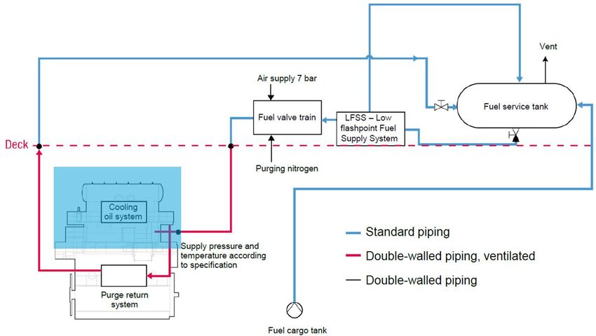
5 IDENTIFICATION OF TECHNOLOGY READINESS 5.1 Introduction The IMO’s International Code of Safety for Ships using Gases or other Low-flashpoint Fuels (IGF Code), ref. /18/, is to provide an international standard for ships using low-flashpoint fuel. The basic philosophy of this Code is to provide mandatory provisions for the arrangement, installation, control and monitoring of machinery, equipment and systems using low-flashpoint fuel to minimize the risk to the ship, its crew and the environment, having regard to the nature of the fuels involved. The IGF code will not be in force until Januray 2017 and will include requirements regarding methanol as fuel at a later stage. Despite of this the various flag states are relating to the IGF Code, since it is adopted by IMO. According to the IGF Code the overall functional requirement is: the safety, reliability and dependability of the systems shall be equivalent to that achieved with new and comparable conventional oil-fuelled main and auxiliary machinery. This level of safety is found by conducting a risk assessment, hazard identificaiton (HAZID) or failure mode, effect and criticality analysis (FMECA), of the fuel system. This is carried out in the design phase, to avoid risks and implement additional risk reducing measures in the design if the risk level is found to be high. The IGF code has been adopted by various Classification Societies and class-rules have been developed based on several years of experience. An extract of the requirements in, DNV GLs Rules for Low Flashpoint Liquid Fuelled Engines, ref. /19/, and the possible risk reduction measures which may be implemented are therefore used as basis in this study. The assessment will further be structured into system elements of the Methanol fuel system and the main differences for certain ship types will be highlighted. 5.2 System breakdown The assessment is further divided into the following system elements: Bunkering of methanol Storage of methanol on board Methanol handling and processing towards the main engine Combustion of methanol in the main engine Methanol handling and processing after the main engine These system elements constitute the whole methanol fuel system, which is presented in Figure 5-1 and further discussed in the following sections. DNV GL – Report No. 2015-1197, Rev. 2 – www.dnvgl.com Page 20
Figure 5-1 Schematic overview of the methanol fuel system, ref. /20/ Safety aspects and technology scope may be different for different ship types, due to the purpose and design of the ship. These differences will be highlighted by dividing into three different ship types, in the following breakdown: Working ships, e.g. offshore supply vessels Cargo ships, e.g. tankers and bulk carriers Passenger ships, e.g. cruise ships and ferries 5.2.1 Bunkering of methanol Requirements regarding bunkering of methanol are according to DNV GLs rules (ref. /19/) divided into the bunkering station and the fuel bunkering system individually: Fuel bunkering station: The bunkering station shall be so located that sufficient natural ventilation is provided. The bunkering station shall be separated from other areas of the ship by gas tight bulkheads, except when located in the cargo area on tankers. Closed or semi-enclosed bunkering stations will be subject to special consideration with respect to requirements for mechanical ventilation. Coamings shall be fitted below the bunkering connections. Control of the bunkering shall be possible from a safe location in regard to bunkering operations. At this location the tank level shall be monitored. Overfill alarm and automatic shutdown is also to be indicated at this location. DNV GL – Report No. 2015-1197, Rev. 2 – www.dnvgl.com Page 21
Fuel bunkering system: A manually operated stop valve and a remote operated shutdown valve in series, or a combined manually operated and remote valve shall be fitted in every bunkering line close to the shore connecting point. Bunkering pipes shall be self-draining. Bunkering lines shall be arranged for inerting and gas freeing. The connecting coupling for the transfer hose shall be of a type which automatically closes at disconnection (self-sealing type). None of these aspects are of a new and complicated nature. These systems already exists in many applications, e.g. for several ships using LNG as fuel within different ship segments. This system breakdown is therefore considered as mature technology. Addressed safety aspects: The configuration of the bunkering station and bunkering system is more comprehensive compared to conventional fuel oil, due to the nature of methanol as a fuel and its chemical and physical properties. Methanol is toxic and has a low flash point of only 12 °C. Flashpoint is the minimum temperature at which a liquid gives off vapour in sufficient concentration to form an ignitable mixture with air. This Methanol property in combination with a low needed ignition energy result in additional control barriers. Additional monitoring and control systems are therefore needed, such as overfill alarms, automatic shutdown, monitoring of ventilation and gas detection, which is stated in the rules presented above. These safety barriers are also meant to minimize methanol exposure to personnel, due to its toxic properties. Methanol is toxic if swallowed, comes in contact with skin or if vapour is inhaled. If methanol is ingested in relative large quantities it will metabolized to formic acid or formate salts, which is poisonous to the central nervous system and may cause blindness, coma and death. The high toxicity level implies that if as little as 10 mL of pure methanol is ingested, it can break down into formic acid, which can cause permanent blindness by destruction of the optic nerve. 30 mL is potentially fatal, although the median lethal dose is about 100 mL. The toxic effects take hours to start, and effective antidotes can often prevent permanent damage. DNV GL – Report No. 2015-1197, Rev. 2 – www.dnvgl.com Page 22
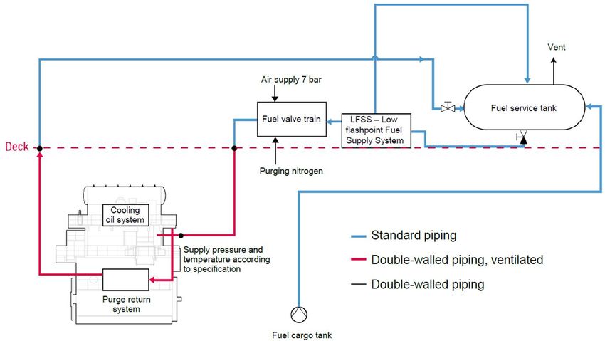
5.2.2 Storage of methanol on board Storage of methanol on board is outlined in the schematic overview of the methanol fuel system presented in Figure 5-2. This part of the methanol fuel system consists of a fuel cargo tank in addition to a fuel service tank placed on deck. This is not the only possible solution regarding storage of methanol as fuel, but used as example in this study for illustration purposes. Figure 5-2 Storage of methanol on board, ref. /20/ Requirements regarding storage of Methanol are according to the rules (ref. /19/) divided into location of fuel tanks, protection of fuel tanks, gas freeing, inerting, venting of fuel tanks and special concerns regarding tanks placed on weather decks. Location of fuel tanks: Fuel shall not be stored within machinery spaces or accommodation spaces and the minimum horizontal distance between the fuel tank side and the ship's shell shall be at least 760 mm. The spaces forward of the collision bulkhead (forepeak) and aft of the aftermost bulkhead (afterpeak) shall not be arranged as fuel tanks. Two fuel service tanks for each type of fuel used on board necessary for propulsion and vital systems or equivalent arrangements shall be provided. Each tank shall have a capacity sufficient for continuous rating of the propulsion plant and normal operating load at sea of the generator plant for a period of not less than 8 hours, if only methanol is used as fuel. Protection of fuel tanks located inside the ship hull: Where not bounded by bottom shell plating or fuel pump room, the fuel tanks for Low Flashpoint Liquid (LFL) shall be surrounded by protective cofferdams. DNV GL – Report No. 2015-1197, Rev. 2 – www.dnvgl.com Page 23
The protective cofferdam surrounding the LFL fuel tank shall be arranged with vapour and liquid leakage detection and possibility for water filling upon detection of leakage. The water filling shall be through a system without permanent connections to water systems in non-hazardous areas. Emptying shall be done with a separate system. Bilge ejectors serving hazardous spaces shall not be permanently connected to the drive water system. Gas freeing, inerting and venting of fuel tanks: Fuel tanks shall be provided with an arrangement for safe inert gas purging and gas freeing. Fuel tanks without direct access from open deck shall have a sufficient number of ventilation inlets and outlets to ensure complete gas-freeing, but no less than 2 inlets and 2 outlets per tank. The tanks shall have an arrangement for pressure/vacuum relief or equivalent during voyage, bunkering and fuel transfer with closed tank hatch covers. Individual pressure vacuum relief valves or an equivalent arrangement shall be fitted to each tank to limit the pressure or vacuum in the tank. The venting system shall be designed with redundancy for the relief of full flow overpressure and vacuum. Pressure sensors fitted in each fuel tank, and connected to an alarm system, may be accepted in lieu of the redundancy requirement for pressure relief. Pressure/vacuum safety valves shall be located on open deck and shall be of a type which allows the functioning of the valve to be easily checked. Intake openings of pressure/vacuum relief valves shall be located at least 1.5 m above tank deck, and shall be protected against the sea. The vent system shall be sized, allowing for flame screens, if fitted, to permit bunkering at a design rate without over-pressuring the tank. Specifically, under conditions in which a saturated fuel vapour is discharged through the venting system at the maximum anticipated bunkering rate, the pressure differential between the fuel tank vapour space and the atmosphere shall not exceed the design vapour pressure of the tank, or, for independent tanks, the maximum working pressure of the tank. The venting system shall be connected to the highest point of each fuel tank and vent lines shall be self-draining under all normal operating conditions of list and trim. The arrangement for gas freeing fuel tanks shall be such as to minimize the hazards due to the dispersal of flammable vapours in the atmosphere and to flammable vapour mixtures in a fuel tank. The ventilating system used for gas freeing of fuel tanks shall be used exclusively for ventilating purposes. Fuel tanks on weather deck: LFL fuel tanks on open deck shall be protected against mechanical damage. LFL deck tanks on open deck shall be surrounded by coamings. Special considerations shall be taken to minimize any fire hazards adjacent to the fuel tanks on weather deck. Protection of the LFL fuel tanks from possible fires on board may be subject to a fire safety assessment in each particular case. The requirements regarding placement and protection of tanks may imply that additional space must be allocated for storage of methanol on board. The requirements regarding gas freeing, inerting and venting DNV GL – Report No. 2015-1197, Rev. 2 – www.dnvgl.com Page 24
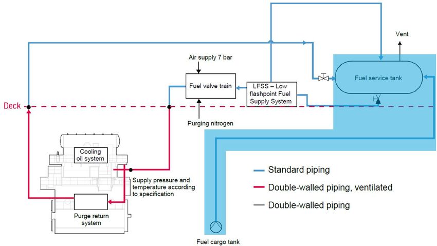
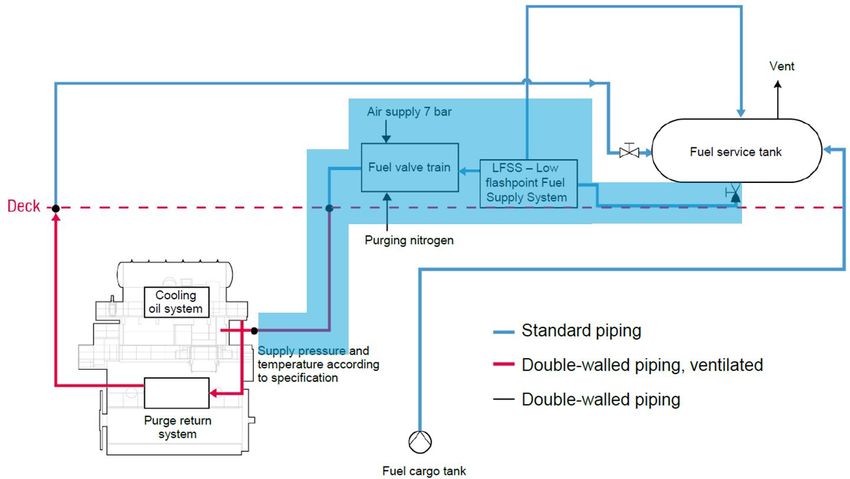
of the tanks involve fitting of equipment, such as pressure/vacuum relief valves, shut-off valves, venting system and pressure sensors connected to alarms. These are all well-known systems and components and are used all over the maritime industry, but may involve an increased installation cost. As opposed to fuel oil, methanol properties enable storage of methanol in double bottom tanks, since it is not considered harmful to the environment. Addressed safety aspects: The configuration of the methanol fuel storage tank is more complex compared to conventional fuel oil, due to the nature and properties of methanol as a fuel. Additional monitoring and control systems are needed, such as overfill alarms and shutdown, monitoring of ventilation liquid and gas detection. Fire detection systems in spaces adjacent to fuel storage and firefighting systems are also needed. Especially fire detection systems are important, due to the fact that a methanol-based fire burns invisibly, unlike gasoline, which burns with a visible flame. Fire detection with infrared cameras is therfore a possible solution to this problem in combination with water spray firefighting systems. 5.2.3 Handling and processing of methanol towards the main engine Handling and processing of methanol towards the main engine is outlined in the schematic overview of the system presented in Figure 5-3. This part of the fuel system consists of a fuel supply system and a fuel valve train placed on deck. Figure 5-3 Handling and processing of Methanol towards the main engine, ref. /20/ Requirements regarding handling and processing of Methanol towards the main engine, according to the rules, (ref. /19/) are divided into general issues, protection of fuel transfer system, valves, fuel pumps and temperature control. General: The fuel system shall be entirely separate from all other piping systems on board. The piping shall be located no less than 760 mm from the ship side. DNV GL – Report No. 2015-1197, Rev. 2 – www.dnvgl.com Page 25
For vessels using LFL as their only fuel, the fuel supply system shall be arranged with redundancy and segregation all the way from the fuel tank to the consumer, so that a leakage in the fuel supply system with following necessary safety actions does not lead to loss of propulsion, power generation or other main functions. All piping containing LFL shall be arranged for gas-freeing and inerting. The design pressure p is the maximum working pressure to which the system may be subjected. The design pressure for fuel piping is as a minimum to be taken as 10 bar. Due consideration shall be given to possible liquid hammer in connection with the closing of valves. Drip trays shall be installed below all possible leakage points in the fuel system. Protection of fuel transfer system: Fuel piping shall be protected against mechanical damage. All piping containing LFL that pass through enclosed spaces in the ship shall be enclosed in a pipe that is gas tight and water tight towards the surrounding spaces with the LFL contained in the inner pipe. Fuel piping shall normally not be lead through accommodation spaces, service spaces or control stations. In cases where fuel piping must be led through accommodation spaces, the double walled fuel piping shall be led through a dedicated duct. The duct shall be of substantial construction and be gas tight and water tight. The annular space in the double walled fuel pipe shall be ventilated to open air and be equipped with vapour and liquid leakage detection. Inerting of the annular space in the double walled fuel piping may be accepted as an alternative in low pressure fuel systems. The inerted annular space shall be pressurised with inert gas at a pressure greater than the fuel pressure. Suitable alarms shall be provided to indicate a loss of inert gas pressure between the pipes. Valves: LFL storage tank inlets and outlets shall be provided with remotely operated shut-off valves located as close to the tank as possible. The tank valve shall automatically cut off the LFL supply. Valves that are required to be operated during normal operation and which are not accessible shall be remotely operated. Normal operation in this context is when fuel is supplied to consumers and during bunkering operations. The main supply lines for fuel to each engine room shall be equipped with automatically operated master LFL fuel valves. The shut-off valve shall be situated outside the engine room. The master LFL fuel valve is automatically to cut off the LFL supply to the engine room. The LFL fuel supply to each consumer shall be provided with a remote shut-off valve. There shall be one manual shutdown valve in the LFL supply line to each engine to assure safe isolation during maintenance on the engine. All automatic and remotely operated valves are to be provided with indications for open and closed valve positions at the location where the valves are remotely operated. Fuel pumps: DNV GL – Report No. 2015-1197, Rev. 2 – www.dnvgl.com Page 26
Any pump room shall be located outside the engine room, be gas tight and water tight to surrounding enclosed spaces and vented to open air. Hydraulically powered pumps that are submerged in fuel tanks (e.g. deep well pumps) shall be arranged with double barriers preventing the hydraulic system serving the pumps from being directly exposed to the fuel. The double barrier shall be arranged for detection and drainage of possible fuel leakages. LFL pump rooms shall be provided with a dedicated bilge system, operable from outside the pump room. Bilge ejectors serving hazardous spaces shall not be permanently connected to the drive water system. The bilge system may have possibilities for discharge to a suitable cargo tank, slop tank or similar, however taking into account hazards related to incompatibility. Temperature control: The temperature control system shall be arranged as a secondary system independent of other ship's services and shall be provided with valves to isolate the system for each supply line or tank. For any temperature control system, means shall be provided to ensure that, when in any other but the empty condition, a higher pressure is maintained within the system than the maximum pressure head exerted by the fuel tank content on the system. The temperature control circuit expansion tank shall be fitted with a gas detector and low level alarm and be vented to open air. The configuration of the methanol fuel transfer and supply arrangement, from the methanol storage tank towards the main engine, is more complex compared to conventional fuel oil transfer systems. The main contributor to the complexity is the piping arrangement with double walled piping including needed gas- freeing and inerting capabilities, ventilation of annular space with vapour and liquid leakage detection. Added complexity is also due to remotely operated shut-off valves to the tanks, valves operated during normal operation and LFL fuel supply valves to each consumer with their corresponding control system. The added complexity may involve an increased installation cost. Addressed safety aspects: The requirements regarding methanol fuel transfer and supply from the methanol storage tank towards the main engine is more complex, as mentioned above, due to the physical properties of methanol. Methanol has a flashpoint of about 12°C, which is the minimum temperature methanol gives off vapour in sufficient concentration to form an ignitable mixture with air. Double walled piping with sufficient ventilation, in addition to segregation by remotely operated valves throughout the whole supply system is therefore needed. Methanol vapour is heavier than air and it will therefore move downwards, hence is the placement of gas detectors and ventilation at lower elevations essential. There are many valves and pipe connections throughout the methanol handling and processing system. This implies that there are many potential leakage points in the system which needs attention, due to the low viscosity of methanol. This is mainly considered by selecting seals and similar with the correct material properties. DNV GL – Report No. 2015-1197, Rev. 2 – www.dnvgl.com Page 27
5.2.4 Combustion of Methanol in the main engine Combustion of methanol in the main engine is outlined in the schematic overview of the system presented in Figure 5-4. This part of the Methanol fuel system consists of additional methanol booster injectors, a liquid gas injection block fitted on the cylinder, which contains a control valve for methanol fuel injection, a sealing booster activation valve, a forced suction activation valve, a purge valve and methanol fuel inlet/outlet valves. Figure 5-4 Combustion of Methanol in the main engine, ref. /20/ Requirements regarding combustion of Methanol in the main engine is according to, ref. /19/ divided into general issues, functional requirements for dual fuel engines and functional requirements for LFL-only engines. General, which applies to both LFL fuel only and dual fuel engines: Measures shall be taken to ensure effective sealing of injection or admission equipment that could potentially leak fuel into the engine room. Measures shall be taken to ensure that LFL fuel injection pumps and injection devices are efficiently lubricated. The starting sequence must be such that LFL fuel is not injected or admitted to the cylinders until ignition is activated and the engine has reached a minimum rotational speed. In this respect pilot fuel is needed. If ignition has not been detected by the engine monitoring system within expected time after activation of fuel admission or injection valve, the LFL fuel supply shall be automatically shut-off and the starting sequence terminated. DNV GL – Report No. 2015-1197, Rev. 2 – www.dnvgl.com Page 28
Functional requirements for dual fuel engines: LFL dual fuel engines shall be able to start, normal stop and stable low power operation safely. In case of shut-off of the LFL fuel supply, the engine shall be capable of continuous operation on oil fuel only. Changeover to and from LFL fuel operation is only to be possible at a power level where it can be done with acceptable reliability as demonstrated through testing. On completion of preparations for changeover to LFL operation including checks of all essential conditions for changeover, the changeover process itself shall be automatic. On normal shutdown as well as emergency shutdown, LFL fuel supply shall be shut off not later than simultaneously switching to oil fuel mode. Firing of the LFL-air mixture in the cylinders shall be initiated by sufficient energy to ensure effective ignition with corresponding combustion of the LFL-air mixture. It shall not be possible to shut-off the ignition source without first or simultaneously closing the LFL fuel supply to each cylinder or to the complete engine. Functional requirements LFL-only engines: One single failure in the LFL fuel supply system shall not lead to total loss of fuel supply. Development of LFL fuel engines have been carried out since 2012, by MAN Diesel & Turbo, /21/ and Wärtsilä, ref /22/. The MAN B&W ME-LGI engine is a dual fuel solution for low flashpoint liquid fuels. Fuel injection is accomplished by a booster fuel injection valve, using 300 or more bar hydraulic power to raise the fuel pressure to injection pressure. So far 7 of this engine configuration have been ordered, meaning that this configuration is at a relatively early stage in deveopment. The use of methanol also presents lubrication requirements that are substantially different than those of conventional fuels. Using methanol as a fuel generally promotes a cleaner lubricant environment, but induces significantly greater engine wear compared to fuel oil. This wear may affect engine operation and durability. DNV GL – Report No. 2015-1197, Rev. 2 – www.dnvgl.com Page 29
You can also read