Brake Assessment Manual - Assessing and certifying brakes for modified vehicles and individually constructed vehicles - Roads and Maritime Services
←
→
Page content transcription
If your browser does not render page correctly, please read the page content below
Brake Assessment Manual

Assessing and certifying brakes for modified
vehicles and individually constructed vehicles.

Developed in association with the
NSW Vehicle Standards Working Group

AUTHOR:      David Beck
DATE:        April 2021
VERSION:     3.0
REFERENCE:
DIVISION:    Safety, Environment & Regulation

Preface
This Manual was developed by an ad hoc focus group convened under the NSW Vehicle
Standards Working Group, which was established in 2012 by the NSW Minister for Roads
and Ports to ensure industry and stakeholders are represented in developing vehicle
standards and policies in NSW. The Vehicle Standards Working Group is co-chaired by
Transport for NSW and the Australian Confederation of Motor Clubs. The members are:
Australian Automotive Aftermarket Association
Australian Confederation of Motor Clubs
Australian Street Rod Federation
Four Wheel Drive NSW & ACT Inc.
Institute of Automotive Mechanical Engineers
Motorcycle Council of NSW Inc.
Motorsport Australia
Motor Traders' Association of New South Wales
National Roads and Motorists' Association
NSW Motorcycle Alliance
NSW Police Force
Transport for NSW
Vehicle Safety Compliance Certification Scheme - Licensed Certifiers
This Manual was first published in October 2013, and gazetted as an Authority standard
compliance specification in May 2017. It has now been updated and revised based on
practical feedback. The major changes in this version are:
A new section about maintaining safety features which includes additional
requirements for vehicles fitted with electronic stability control
Certain technical features being excluded for ICVs
An amended Brake System Installation Checklist
The section on use of aftermarket components has been amended to refer to a new
document about manufacturer approved components
Test H now includes options such as in fatigue analysis
Note: The document will be updated regularly and is subject to change as necessary.
Brake Assessment Manual | Version 3.0 | April 2021 2 (51 pages)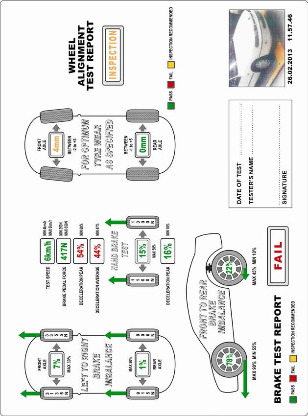
1.      General
1.1     Scope
This ‘Brake assessment manual’ (the Manual) applies to all types of light motor vehicles,
except motorcycles and mopeds. It is intended to be used to assess the brake systems in
modified vehicles and individually constructed vehicles (ICVs), including replica street rods,
as part of the process for certifying the vehicle for registration in accordance with the Road
Transport (Vehicle Registration) Regulation 2017 and the Vehicle Safety Compliance
Certification Scheme (VSCCS). This Manual does not cover the design of brake systems.
The Manual serves as an alternate pathway to compliance in respect of brake testing of
these vehicles. Vehicles certified to comply with specified requirements of the Manual are
exempted from the related requirements of the applicable vehicle standards. The Exemption
notice is included as Appendix H of the Manual.
Notes:
1. The term ‘vehicle’ used in this Manual refers to light vehicles, being vehicles with a gross vehicle
   mass of 4.5 tonnes or less.
2. From hereon, the term ‘modified vehicle’ also applies to ICVs except where stated otherwise.
3. Terms that are italicised are defined in Appendix A.
4. Appendix B contains a checklist to guide modifiers and assist licensed certifiers in certifying the
   vehicle.

1.2     Introduction
The Road Transport (Vehicle Registration) Regulation 2017 (the Regulation) requires that all
registrable vehicles comply with the applicable vehicle standards, and modified vehicles
continue to comply with those standards. It also specifies that the vehicle, its parts and
equipment are suitable for safe use and are in a thoroughly serviceable condition.
To assist vehicle owners in meeting these obligations, Transport for NSW (TfNSW) manages
a modification scheme under the Regulation, the VSCCS. This authorises individual people
with appropriate technical qualifications, training and experience as ‘licensed certifiers’ to
inspect a modified vehicle and where it complies with the applicable vehicle standards, issue
a compliance certificate.
Except for purposes relating to compliance certification, a vehicle that has undergone a
significant modification (i.e. one that requires a compliance certificate) must not be used on a
road or road related area unless a compliance certificate has been issued for the vehicle. For
more information, refer to clauses 60, 64, 84, 85 and 87 of the Regulation.
Vehicle braking systems are critical to crash avoidance. Modifications made to vehicle
brakes or to the vehicle that affects the braking system necessitate that the effectiveness of
the brakes are verified before the vehicle is registered. Similarly, the brakes fitted to an ICV
must be assessed to ensure they meet minimum safety standards, regardless of where the
brakes were sourced. This Manual identifies the types of modifications that affect vehicle
braking systems which require assessment and certification, refer to Section 2.2 Table 1.
Standards for a brake system and components are complex and requires extensive and
often expensive testing. It may be necessary to test at high speed to verify compliance with
requirements. This Manual has been gazetted as an Authority standard compliance
specification in accordance with Clause 64 of the Regulation, as such it may be utilised to
demonstrate that a modified light vehicle complies with the applicable vehicle standards.
Note: Other standards that may be used in assessing a modified vehicle or ICV include the applicable
ADRs and National Vehicle Standards Bulletin 14 National Code of Practice for Light Vehicle
Construction and Modification (VSB 14).
The level of assessment a vehicle must undergo to obtain a compliance certificate is based
on the extent of the modification and the risk posed to the vehicle occupants and road users.
The options for obtaining a compliance certificate for the modified vehicle are:

Brake Assessment Manual | Version 3.0 | April 2021                                            3 (51 pages)
1. Inspection of approved aftermarket components 2. Assessment based on tests previously done on a similar vehicle 3. Application of a series of road tests. With respect to brake systems, adherence with this manual is the pathway to consideration for exemption from the standards. An exemption must be issued by TfNSW before the vehicle can be certified; the certificate then must refer to the specific exemption granted. 1.3 Limits of assessments Assessments detailed in this Manual apply to vehicles intended to be registered for use on the road, under normal driving operations within posted speed limits. If the vehicle is to be use for specialised activities such as motorsports then more rigorous assessment and testing may be required to ensure the braking system is adequate. 1.4 Maintaining vehicle safety features In addition to the provisions for registered vehicles to comply with safety standards, the Regulation requires vehicles to be maintained in a manner that will not cause a danger to any person. Safety features including those not covered by an ADR (or other applicable standard) must remain functional after the modification. With the introduction of complex and sensitive safety features in modern vehicles, such as electronic stability control (ESC) and autonomous emergency braking, particular care must be taken to ensure the systems are not affected negatively by modifications. After significant modification a vehicle may not be issued with a compliance certificate where changes adversely affect the performance of a safety feature. For vehicles equipped with ESC the on-road effect must be scrutinised as part of the licensed certifier assessment. A compliance certificate may only be issued where ESC is shown to be operational without adversely affecting vehicle performance. Where necessary, the ESC may be reprogrammed to maintain expected performance. Video evidence of vehicle stability performance post- modification is expected in the documentation presented with the request for exemption. 1.5 Competence of licensed certifiers TfNSW has assessed the competencies of persons registered as licensed certifiers. The areas of competence for every licensed certifier are published on the TfNSW website. Only licensed certifiers identified as competent in brakes who have the necessary equipment to do the applicable tests may be engaged in assessing and certifying vehicles with modifications to, or that affect their brakes. 1.6 Evidence of compliance Licensed certifiers must maintain evidence and make it available to support every statement of compliance with this Manual as part of the VSCCS certification process. Evidence may include: statements, certificates and test reports from the component manufacturer equipment calibration details data readouts calculations video detailed photographs that clearly and unambiguously show the modification Brake Assessment Manual | Version 3.0 | April 2021 4 (51 pages)
2.      Types of modifications
2.1     Changes that do not require assessment or certification
The following are not considered to be modifications that require assessment or certification:
1.    Replacement of parts or components by identical or equivalent parts or components.
2.    Replacement of parts or components with equivalent functional performance.
3.    Optional parts or components as prescribed by the vehicle manufacturer.

2.2     Modifications that do require assessment
Table 1 sets out significant modifications that require the vehicle’s brake system to be
assessed. The vehicle may be subject to a single modification or a combination of
modifications. If the vehicle has been subject to a number of modifications then the
assessment must ensure that all the modifications are considered.
Table 1: Modifications that require brake system assessment
 Mod.    Description
 1       Relocation of brake pedal/master cylinder.
         Typical example being from the engine bay to the passenger compartment or the underside
         of the vehicle and no other brake modifications.
 2       Single-circuit master cylinder replaced with dual-circuit master cylinder with the same bore
         diameter and no other brake modifications.
 3       Conversion from left-hand drive to right-hand drive by re-fitting original brake master
         cylinder/booster to right-hand side of vehicle or by cross-shafting the original brake master
         cylinder/booster and no other brake modifications.
 4       Fitting an ‘inline vacuum assisted’ brake booster or fitting a full power brake unit to an
         unmodified braking system or to a modified braking system which has been previously
         tested.
         Typical examples: vacuum assist - PBR VH40/VH44, full power -Chevrolet/GMC unit.
 5       Fitting a twin diaphragm, direct-acting brake booster in place of the original single
         diaphragm, direct-acting brake booster.
 6.      Fitting dual or multi-piston brake callipers to original front disc rotors in place of original
         single or multi-piston brake callipers The new dual or multi-piston brake calipers are fitted
         with or without adapting brackets.
 7       Fitting disc brakes to the front of a vehicle without using brake caliper adapting brackets.
         Fitting larger-diameter drum brakes to the front of a vehicle.
 8       Fitting disc brakes to the front of a vehicle with brake caliper adapting brackets.
 9       Fitting disc brakes to the rear of a vehicle without using brake caliper adapting brackets.
         Fitting larger-diameter drum brakes to the rear of a vehicle.
 10      Fitting disc brakes to the rear of a vehicle with brake caliper adapting brackets.
 11      Fitting larger-diameter brake discs to the front of a vehicle with existing or replacement
         brake callipers to suit the larger disc diameter.
 12      Fitting larger-diameter brake discs to the rear of the vehicle with existing or replacement
         brake callipers to suit the larger disc diameter.
 13      Fitting replacement front suspension and brakes from a vehicle of a different make and
         model with or without modification to the replacement suspension.
         Significant modification to original suspension or original suspension mountings.
         Note: Refer to allowable 'Minor modifications' as set out in the Road and Maritime 'Light
         vehicle modifications manual: Suspension and ride height' 2016 TP16/03352.

Brake Assessment Manual | Version 3.0 | April 2021                                               5 (51 pages)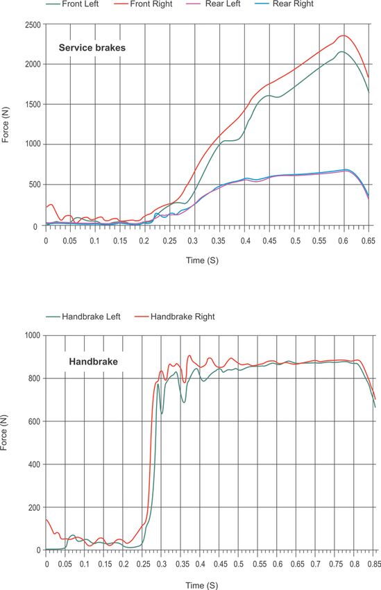
Mod.    Description
 14      Fitting replacement rear suspension and brakes from a vehicle of a different make and
         model with or without modification to the replacement suspension.
         Significant modification to original suspension or original suspension mountings.
         Note: Refer to allowable 'Minor modifications' as set out in the Road and Maritime 'Light
         vehicle modifications manual: Suspension and ride height' 2016 TP16/03352.
 15      Replacement of the original vehicle rear axle assembly and brakes with a different rear axle
         assembly and brakes or with brakes from a different make and model and/or aftermarket
         brake components.
         If original vehicle brakes are retained then utilise the spike stop procedure only. Typical
         example: Ford 9” differential
 16      Replacing the entire braking system with a combination of components either from a
         production vehicle or an aftermarket brake component manufacturer.
 17      ICV with a combination of production car brake components and/or after-market brake
         components.
 18      ICV with brake system components from a 31/01 complying vehicle having less mass than
         the donor vehicle. The components shall comprise at least, rotors, calipers, master cylinder,
         booster and park brake mechanism. Retention of the donor vehicle hand brake lever is not
         mandatory. Additional components such as a proportioning valve may be fitted to obtain
         balanced brake performance. ABS and/or EBS from the donor vehicle shall not be used.
 19      Fitting hydraulic brakes to a vehicle that originally had an un-braked axle or cable-operated
         brakes (with no other modification to the original vehicle present). Future modifications are
         subjected to test item 16.
 20      Change in the mass on the axles by 10% or more with brakes unchanged from those fitted
         and tested prior to the mass change.
         Note: A change in engine with up to 10% greater mass does not require testing.
 21      Engine having a power increase over 20% of that offered:
         - by the vehicle manufacturer (for that model), or
         - from a previously certified modification, or
         - where the maximum speed of the original vehicle was less than 200 km/h (and the brakes
         are unchanged from those fitted and tested prior to the power increase).
 22      Wheels and tyres - A change in the rolling diameter of the wheel and tyre combination in
         excess of +/- 7% which has not been previously tested.
 23      Removal of any form of power assist or full power unit (whether by vacuum, air, or hydraulic
         means) from an existing brake system that results in the driver supplying all the energy to
         apply the brakes.
 24      Removal or alteration to a motion sensitive brake system pressure differential valve.
 25      Removal or alteration to a brake system load sensing or pressure regulating valve (brake
         proportioning valve).
 26      Alteration or modification to a diagonally split braking system using like parts designed for a
         diagonally split braking system and remaining a diagonally split system.
         Typical vehicles that featured such a setup are Volvo, Lancia, and Ferrari.
 27      Alteration or modification to a diagonally split braking system not using like parts designed
         for a diagonally split braking system and converting it to a conventional front/rear dual circuit
         braking system in the process.
 28      Removal of a brake system pressure differential valve from a manufacturer’s standard and
         unmodified braking system.
         This modification can only be done if the vehicle is also modified to address the risk
         introduced. It must not be done if a vehicle is otherwise unmodified.
 29      Modification to the brake power unit of a hydraulic brake system which has been previously
         tested and which incorporates pumps and accumulators also known as a full power braking
         system.

Brake Assessment Manual | Version 3.0 | April 2021                                             6 (51 pages)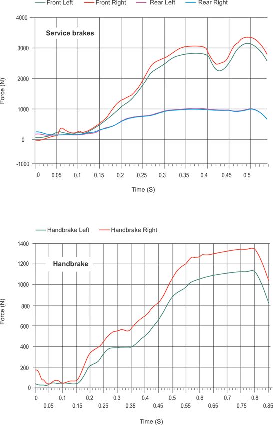
Mod.    Description
         Typical examples: Chevrolet/GMC and the like.
 30      Modification or alteration to electro-hydraulic full power braking system.
 31      Modification or alteration to regenerative brake systems.

The modification categories listed above are not exhaustive. Further categories may be
added over time.

2.3     Modifications not permitted
A vehicle hydraulic brake system that incorporates pumps and accumulators (also known as
‘full power braking systems’) must not be modified.

Brake Assessment Manual | Version 3.0 | April 2021                                    7 (51 pages)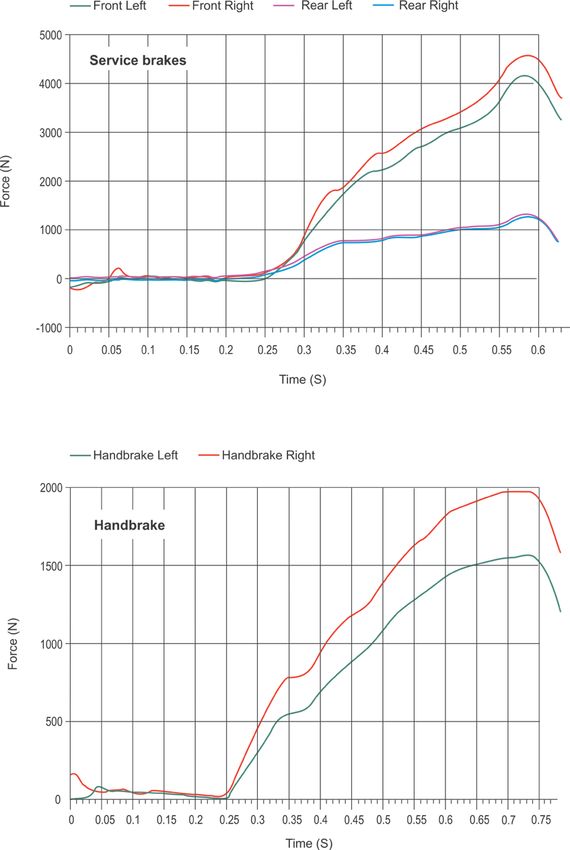
3. Method
3.1 Method 1 – Approved aftermarket components
The requirements for using aftermarket components in modifying or building a vehicle are
specified in the document Using manufacturers approved aftermarket components in
modified light vehicles, which can be accessed on the NSW TfNSW website.
Verification that the component(s) meet the conditions specified in this document and have
been manufactured to a suitable standard being compatible with the host vehicle. This may
be demonstrated by certification from a company accredited to the National Association of
Testing Authorities or another body registered with the International Laboratory Accreditation
Cooperation accredited body.
3.2 Method 2 – Tests to similar vehicles
If a vehicle has been modified using a braking system or components identical to those from
a similar vehicle (that are within the tolerances listed in Table 2) and it has already been
assessed and certified, then a licensed certifier may issue a certificate of compliance without
the need for testing provided the following conditions are satisfied:
the engines are mounted in equivalent locations
the components are identical to those used in the certified vehicle
the components are examined to establish that they are in good condition
a detailed examination of the vehicle is made to confirm suitability for properly
accommodating the components, such as load-bearing members that display no
evidence of structural degradation
a detailed examination of the vehicle is made to ensure that the components have
been correctly installed
results of the assessment, including test results made on the similar vehicle with
reference in the test report.
The licensed certifier must do the examinations listed above. A record of the examination
and the evidence used to determine that the two vehicles are similar must be retained.
The results only apply for vehicles that are similar to the tested vehicle and must not be used
for a vehicle once-removed, as follows:
If Vehicle X is tested and Vehicle Y is similar to Vehicle X, then tests obtained for Vehicle X
can be applied to Vehicle Y.
If Vehicle Z is similar to Vehicle Y but not similar to Vehicle X (i.e. it is outside the
parameters), then test results cannot be applied to Vehicle Z.
NB: This method also applies to standard vehicles manufactured to the ADRs and
supplied to the market in accordance with standard Compliance Plate Approval
Scheme administered by the Department of Infrastructure, Transport, Regional
Development and Communications or any of its predecessors and successors.
Brake Assessment Manual | Version 3.0 | April 2021 8 (51 pages)Table 2: tolerances for determining a similar vehicle
Parameter Tolerance
Individual unladen axle mass + 10%
Wheel base ± 20%
Centre of gravity ± 50 mm in height
Note: The following external website may provide a
useful reference on determining the centre of gravity:
http://brakepower.com/help_abc_07_YCG_t.htm.
Power + 20% if this results in an increased rate of
acceleration or maximum speed where the
maximum speed of the original vehicle was
less than 200 km/h
Tyre size ± 7% in rolling diameter
For particular requirements of handbrakes, refer to Appendix C.
3.3 Method 3 – Installation checklist, static brake test and assessment
3.3.1 General
Assessment by a licensed certifier
Licensed certifiers must assess the modified vehicle to determine that it:
Does not present a safety risk
Would comply with the applicable vehicle standards should it be subjected to the full
range of tests specified by the standards.
The initial assessment shall comprise of a detailed inspection of the vehicle taking account of
the installation checklist provided by the modifier, the condition of the vehicle, and the
condition of the components. This should include a review of the data produced by the static
brake test machine.
The following stages of assessment apply:
1. The modifier checks the brake components using the checklist in Appendix B.
2. The modifier presents the modified vehicle to a licensed certifier or a facility approved
by Transport for NSW for brake tests using a static brake test machine. Note:
- Authorised Inspection Stations that do safety checks (i.e. ‘Pink slip’ tests) are
‘approved facilities’ and many have appropriate static brake test machines.
- Verify that the test machine has a current certification certificate before testing
3. The modifier takes the modified vehicle, the completed installation checklist, and the
data read-outs from the static brake tests to a licensed certifier for assessment.
4. The vehicle and associated information is assessed by the licensed certifier.
The certifier determines whether sufficient information exists to warrant issuing a
compliance certificate, or whether ‘Additional tests’ are required (as set out following).
Note: A static test machine may not provide the licensed certifier with sufficient
information to form an opinion as to whether the vehicle complies with these
standards, especially for vehicles that comply with ADR 31/--, that is vehicles
manufactured after 1 January 1977.
Brake Assessment Manual | Version 3.0 | April 2021 9 (51 pages)3.3.2 Additional tests
General
Based on the results obtained from the static brake test machine and the type of modification
being assessed, the licensed certifier may require the modified vehicle to undertake
additional tests. Table 3 outlines the range of tests which can be used to verify the
modifications listed in Table 1.
Non-road tests
A number of the tests listed in Table 3 can be done on a static brake test machine. Tests on
static machine must be performed by a person trained and competent in its use. The
licensed certifier must be satisfied the tests were performed correctly and relate to the
vehicle being assessed. It is recommended that the certifier observe the tests performed.
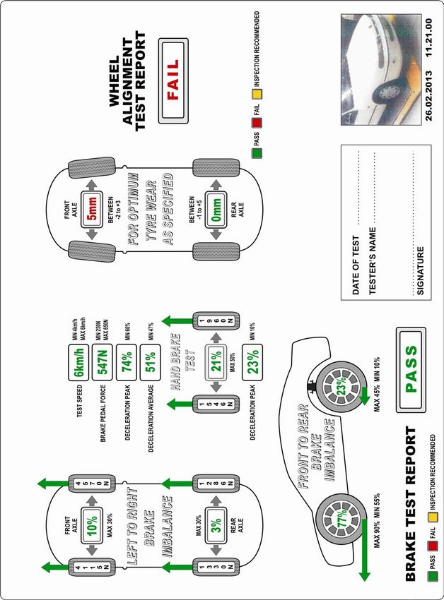
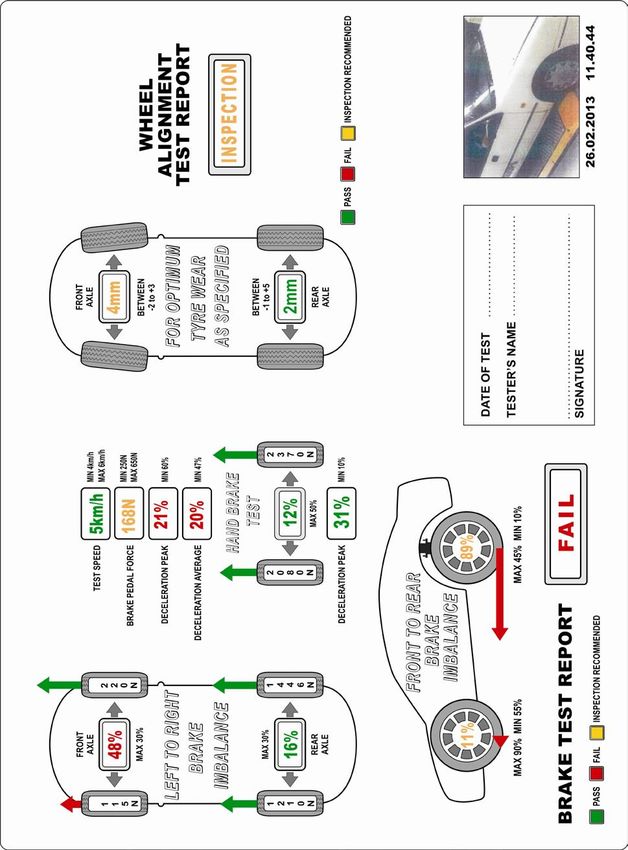
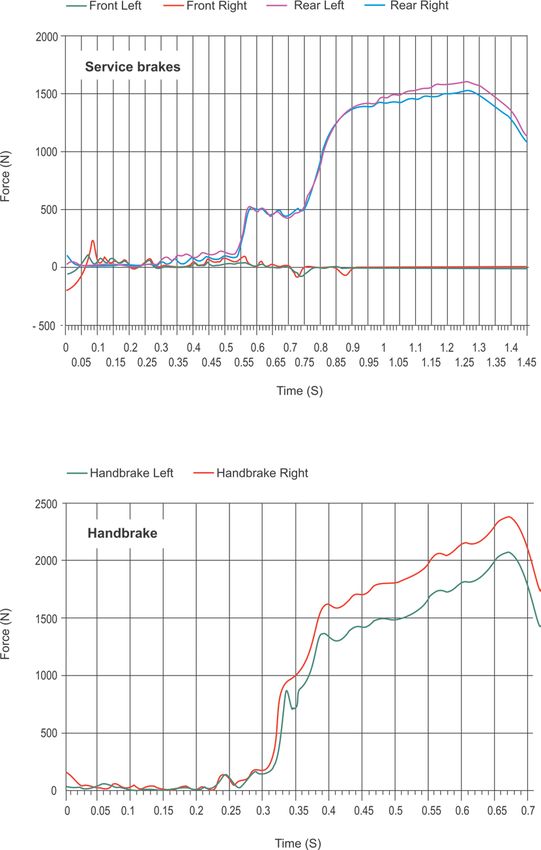
Appendix D (Using a plate-type test machine) provides an example of how a plate-type brake
test machine can be used to do the basic and additional tests. At the time of writing, data
was only available for this type of brake test machine. Additional appendices will be
developed when data from other machines types become available. A manufacturer or
supplier that would like a particular type of machine can make a submission to
roadsafety@transport.nsw.gov.au.
Other tests may be done statically. The licensed certifier must supervise these tests, namely:
Test A: Reservoir volume
Test C: Park brake
Road tests
If the tests required by the licensed certifier need to be done on a road or a road-type test
facility then the conditions specified under ‘Method 4 – Road tests’ apply.
3.4 Method 4 – Road/track tests
3.4.1 General
There are few details available of the brake standards that were used before the introduction
of ADR 31 ‘Brake systems for passenger cars’ in 1977. For this reason, the tests specified in
Appendix E are derived from ADR 31/00 and ADR 31/01 which contain the least onerous
tests.
The tests have been modified considerably so that they can be applied to all vehicles
regardless of the date of manufacture, and to make the tests affordable and practicable while
retaining safety considerations. For more information about the rationale used to develop the
test schedule, refer to Appendix F.
The key elements of the test schedule relative to those specified in the ADRs:
Typically, fewer repeat runs required
Lower speeds permissible where appropriate justification is given, for example with the
unavailability of a test track or a suitable high-speed road.
The applicable tests for the different modifications are given in Table 3 and described in
Appendix E. Appendix G has variations that apply to N Category and certain M Category
vehicles. Where a vehicle has been subjected to a combination of modifications, some test
Brake Assessment Manual | Version 3.0 | April 2021 10 (51 pages)items may happen to be duplicated. In such circumstances it is not necessary to duplicate a
test item, although the combination of test items are required to be completed.
The Regulation allows an unregistered vehicle to be driven for testing on NSW roads for the
purpose of determining whether the vehicle complies with the applicable vehicle standards.
The reduction in test speed and number of test runs make it possible to test some modified
vehicles on public roads under controlled conditions. Refer to 3.4.4 ‘Test conditions’.
3.4.2 Competence of drivers
The vehicle should be driven by a competent person capable of efficiently achieving the
specified test operations.
Note: The successful execution of the tests in Appendix E may depend on competence of the person
driving the vehicle. If the specified test conditions are not met there may be excessive tyre wear or
other maintenance outcomes.
3.4.3 Test equipment
It is important that appropriate equipment is used to measure and record test-critical data.
The following types of equipment must be used as a minimum:
an inertial-type direct reading deceleration meter (that is capable of reading the MFDD).
An exception to this is for modifications 6-10, see Table 1.
Note: Alternatively, a device capable of measuring the average deceleration may be used, in which
case the average deceleration reading must be at least equal to the MFDD specified.
a pedal force gauge
a device such as a fifth wheel or GPS (Global Positioning System) unit for measuring
speed
data logging equipment (mandatory) for all tests specified in Appendix E
a GPS device may be used for measuring and recording distance and time (and therefore
average deceleration).
Note: The vehicle speedometer should not be used as test reference.
The equipment used must function correctly and accurately. Equipment requiring calibration
must be within certification for testing and records retained to verify. The equipment must be
capable of recording the relevant test data to facilitate verification and audit. Tolerance on
test speeds shall be +/- 3 km/h, and instrumentation accuracy shall be +/- 3 %.
Note: Tolerances are not cumulative.
3.4.4 Test conditions
The following test conditions apply:
Location:
– For tests that cannot legally be performed on a public road (such as those requiring
high speeds) an appropriate venue must be used (like a dedicated test track, race
circuit, or aerodrome)
– Where tests can be safely conducted on a public road, the necessary approval must be
granted prior by the applicable road authority. For local roads this is the local council,
for State and Federal roads in NSW the authority is TfNSW.
A location specific risk assessment must accompany the application regarding
suitability. All stipulated controls must be complied with, for example the use of
accredited traffic controllers with a traffic control plan in place.
– Dynamic tests must be conducted on a dry road that is either level or inclined slightly
downhill, and which has a sealed surface or another surface affording good adhesion.
(With exception of Test I).
Brake Assessment Manual | Version 3.0 | April 2021 11 (51 pages)– The road must be sufficiently long and straight to enable the full range of tests to be
carried out safely, with sufficient run-off in case of brake failure.
Inspection - The certifier must inspect the vehicle prior, ensuring that it can be driven
safely. Pre-test controls must be implemented before commencement. Refer to section
3.4.5 ‘Pre-test check’.
Vehicle:
The certifier must inspect the vehicle prior to driving it to the place of testing, to ensure
that it can be driven safely.
– The tyres are to be ‘cold’ (i.e. at ambient temperature) and inflated to an appropriate
pressure for the vehicle to operate safely at its design load/speed.
– The vehicle must be at maximum loaded test mass (unless otherwise specified).
The loaded mass must be evenly distributed among the axles as specified by the
vehicle manufacturer.
– The transmission must be disconnected for each test (unless otherwise specified)
Testing:
– General behaviour of the vehicle during braking must be observed.
Test results (unless otherwise specified) must be achieved without severe or abnormal
vibrations and without the vehicle:
- locking wheels at speeds exceeding 15 km/h
- departing from a 3.5 m wide lane
- exceeding a yaw angle of 15 degrees
– If the maximum speed of the vehicle is lower than the speed prescribed for a particular
test then the test shall be performed at the Maximum Vehicle Speed.
3.4.5 Pre-test check
In the interests of road safety before doing any of the tests outlined in Appendix E, the
vehicle should be thoroughly examined to ensure it is in a roadworthy condition. The
competent person testing brakes should check prior to the test that:
the vehicle is in good order and the brake lights are all functioning correctly
the vehicle modifier has affirmed that the type of brake fluid used is appropriate for the
braking system and in good condition
the correct fluid identification symbols are used and affixed in a visible position in indelible
form within 150 mm of the filling ports of the fluid reservoirs
modification to the brake system is complete and free of known and obvious defects
the wheels and tyres are appropriately inflated, and inflation pressures recorded
for modified vehicles, the wheel alignment is within specified safety limits
the vehicle is structurally sound and will withstand the likely stresses induced in the tests
the vehicle passes a rudimentary brake test as follows
o with the vehicle in the unladen state, accelerate to over 35 km/h
o put the transmission into neutral and coast down to 30 km/h
o with both hands on the steering wheel, bring the vehicle to a stop as quickly as
possible with one sustained and smooth braking action using the service brake
control
o that the vehicle does not pull to one side
o that the brake pedal pressure must not exceed 885 N for full braking
o average deceleration rate for the service brake must be at least 2.9 m/s2
o peak deceleration rate for the service brake must be at least 3.4 m/s2.
Brake Assessment Manual | Version 3.0 | April 2021 12 (51 pages)If the vehicle does not meet the preceding listed requirements then it is not eligible for testing outlined in Appendix E. Ensure that the test instrumentation is functioning correctly by performing (no more than 20) decelerations. For vehicles subject to Modification 19, the deceleration shall be done from a speed of 40 km/h; for all other vehicles conducted decelerations from a speed no more than 65 km/h. In all cases, the actual deceleration must not exceed 3.5 m/s2. 3.4.6 Notes in relation to testing 1. When doing the series of tests they must be done as specified. This is both a safety matter and avoids unnecessary damage to the vehicle, including brake components and tyres. Ensure the vehicle is driven at the specified speeds with the specified maximum force to apply the brakes. 2. The licensed certifier must be satisfied that that the tests specified in Table 3 are sufficient to certify the subject vehicle. Test speeds may be increased should the test speeds in Table 3 be deemed insufficient to properly assess vehicle braking performance based on dynamic capabilities. The test speeds may not be decreased. 3. The test schedule is not necessarily exhaustive and further testing may be necessary at the discretion of those carrying out the brake testing. 4. It is not necessary to do a test as specified for one modification if the test has been done for another modification. 5. Tests done on public roads must comply with the conditions specified by the applicable road authority; and not interfere with or disrupt traffic; pose a risk to the persons doing the tests and other road users; or cause damage to the road and roadside infrastructure. 6. Testing that can be achieved at a single test mass deem it not necessary to carry out both tests (i.e. for both laden and unladen conditions). In such circumstances, the more onerous test conditions apply. Brake Assessment Manual | Version 3.0 | April 2021 13 (51 pages)
Table 3: Test Schedule – see the following page for notes
A* B + C* D + E + F + G + H I + J1 K L M N
Disconnected/
Test
performance
performance
Proportion
procedure
procedure
front rear
Reservoir
Mounting
Recovery
Recovery
structure
Heating
Booster
volume
Type-0
failure
Failure
Engine
Type-I
Type-I
Type-I
Type-I
Partial
failure
failure
Wheel
Brake
Spike
stops
valve
lock
Park
ABS
Hot
Modification
1 T
2 T T
3 T
4 T T
5 T T
6 T T T T T T T T T
7 T T T T T T T T T
8 T T T T T T T T T
9 T T T T T T T T T
10 T T T T T T T T T T
11 T T T T T T T T T T T T T
12 T T T T T T T T T T T T T T
13 T T T T T T T T T T T T T
14 T T T T T T T T T T T T T T
15 T T T T T T T T T
16 T T T T T T T T T T T T T T
17 ICV T T T T T T T T T T T T T
18 ICV Donor T T T T T
19 T T T T T T T
20 T T T T T T
21 T T T T
22a T
22b T T T T T
22c T T T T T T
23 Full test to applicable ADRs
24 T
25 T
26 T T T T T T T T T T T T T T
27 T T T T T T T T T T T T T T
28 T
29 T T
31 Full test to applicable ADRs
Brake assessment manual Ver 3.0 April 2021 14 (51 pages)Key to Table 3: Reference Description * The test does not need to be done on a road or road-type test facility + A static brake test machine may be appropriate for this test T Testing is required for the modification. Refer to Appendix E for details of the tests. 22a Vehicles with a change in tyre/wheel diameter less than 26 mm 22b Vehicles not fitted with ABS with a change in tyre/wheel diameter greater than 26 mm 22c Vehicles fitted with ABS with a change in tyre/wheel diameter greater than 26 mm Brake assessment manual Ver 3.0 April 2021 15 (51 pages)
Appendix A: Glossary
The terms below are used in this Manual. Except for those marked with an asterisk (*), they
have been taken from ‘Australian Design Rules - Definitions and Vehicle Categories’; and
those marked (†) have been amended specifically for this Manual. To identify where they are
used, they are italicised in the text.
ADR vehicle - a vehicle that was manufactured after to the introduction of ADR 31 on 1
January 1977.
Antilock System - a portion of a service brake system that automatically controls the degree
of rotational wheel slip relative to the road at one or more road wheels of the vehicle during
braking
Average Deceleration - the number determined by dividing the square of the initial vehicle
speed by twice the stopping distance expressed in compatible units.
Axle - one or more shafts positioned in a line across a vehicle, on which one or more wheels
intended to support the vehicle turn.
Axle Load - total load transmitted to the road by all the tyres of all the wheels whose centres
may be included between two transverse parallel vertical planes less than one metre apart.
Brake Power Assist Unit - a device installed in a hydraulic brake system that reduces the
operator effort required to actuate the system and that if inoperative does not prevent the
operator from braking the vehicle by a continued application of muscular force on the service
brake Control.
Brake Power Unit - a device installed in a Brake System that provides the energy required to
actuate the Brakes, either directly or indirectly through an auxiliary device, with the operator
action consisting only of modulating the energy application level.
Brake System - all those systems and devices attached to the vehicle whose primary
function is to translate energy and/or muscular effort of the driver, or in the case of trailers,
energy and/or information supplied by the towing vehicle into a force that restrains vehicle
movement.
Brakes - those Friction Elements that are forced together by the influence of the remainder of
the brake system so as to apply a restraining torque to the vehicle wheels.
* Cold brakes - brakes that have disc temperatures below 100ºC.
Competent person - a person who has acquired through a combination of training,
qualification and experience the knowledge and skills necessary to carry out a specified task.
Control - a component actuated directly by the operator to transmit the force required to
activate the brake system.
* Fade - reduction in braking effectiveness caused by excessive heat that can occur after
repeated or sustained application of the brakes.
Friction Element - a part of the system designed for replacement and which contacts another
part of the system in such a way that either vehicle kinetic energy is dissipated or the vehicle
is restrained from moving.
Gross Vehicle Mass - the maximum laden mass of a motor vehicle as specified by the
Manufacturer.
Laden Mass - the mass of a vehicle and its load borne on the surface on which it is standing
or running.
Lightly Loaded Test Mass (LLTM) - the mass of the Unladen vehicle with a full capacity of
lubricating oil and coolant and not less than 75% of full fuel capacity but without goods,
occupants or options except those options which are essential for the test procedures
specified, plus additional loading distributed in the seating position adjacent to the driver’s

Brake assessment manual             Ver 3.0           April 2021                        16 (51 pages)
seating position so that the mass of such loading plus the mass of the driver and
instrumentation mounted in the vehicle is 155 ± 30 kg.
M Category Vehicles
      MA Passenger Car - a passenger vehicle, not being an off-road passenger vehicle or a
      forward-control passenger vehicle, having up to 9 seating positions, including that of
      the driver.
      MB Forward-Control Passenger Vehicle - a passenger vehicle, not being an off-road
      passenger vehicle, having up to 9 seating positions, including that of the driver, and in
      which the centre of the steering wheel is in the forward quarter of the vehicle‘s total
      length.
      MC Off-Road Passenger Vehicle - a passenger vehicle having up to 9 seating
      positions, including that of the driver and being designed with special features for off-
      road operation.
      MD Light Omnibus - a passenger vehicle having more than 9 seating positions,
      including that of the driver and with a Gross Vehicle Mass not exceeding 5.0 tonnes.
Manufacturer - the name of the person or company who accepts responsibility for
compliance with the Australian Design Rules and to whom the ‘Compliance Plate’ approval
certificate is issued, or, for an individually constructed vehicle, the person in whose name the
vehicle is registered.
†
 Maximum Loaded Test Mass (MLTM) - the mass of the Unladen vehicle together with a full
capacity of lubricating oil and coolant and at least 75% capacity of fuel plus additional mass
equivalent to 68 kg located in each unoccupied seating position.
†
 Maximum Vehicle Speed - the speed attainable, established by calculation or on the basis
of a test, under maximum vehicle acceleration from a standing start for 1.6 km.
Modifier - the owner or the registered operator of a vehicle as used in the Regulation,
whether or not the person actually does the modifications themselves.
MFDD – the mean fully developed deceleration. An explanation for how to calculate this is
included in aDR31/04.
N Category Vehicles
      NA Light Goods Vehicle - a goods vehicle with a Gross Vehicle Mass not exceeding
      3.5 tonnes.
      NB1 Medium Goods Vehicle - a goods vehicle with a Gross Vehicle Mass between 3.5
      tonnes and 4.5 tonnes.
      Goods Vehicle - a motor vehicle constructed primarily for the carriage of goods and
      having at least 4 wheels; or 3 wheels and a Gross Vehicle Mass exceeding 1.0 tonne.
* OEM - Original Equipment Manufacturer
Parking Mechanism - a component or sub-system of the drive train that locks the drive train
when the transmission control is placed in the ‘park’ position or other gear position and the
ignition key is removed.
Pedal Effort - the force applied to the service brake Control. The force may be measured by
a force transducer located centrally on the brake pedal pad.
Pre-ADR vehicle – a vehicle that was manufactured prior the introduction of ADR 31 on 1
January 1977, or a vehicle that meets the requirements of the National Guidelines for the
Construction and Modification of Street Rods in Australia.
* Restored vehicle - a vehicle that is being or has been restored to its manufacturer’s
specifications, so far as it is reasonably practicable to meet those specifications.
Note: This definition is from the Road Transport (Vehicle Registration) Regulation 2017.

Brake assessment manual              Ver 3.0            April 2021                         17 (51 pages)
Split Service Brake System - a brake system consisting of two or more sub-systems actuated by a single Control and so designed so that a leakage-type failure of a pressure component in a single sub-system (except structural failure of a housing that is common to all sub- systems) shall not impair the operation of any other sub-systems. Stored Energy - energy stored in a device such as a pressure vessel, vacuum chamber, spring or battery. † Unladen Mass - the mass of the vehicle in its operational configuration, unoccupied and unladen with all fluid reservoirs filled to nominal capacity including fuel. Variable Proportioning Brake System - system that automatically adjusts the braking force at the Axles to compensate for vehicle static Axle Load and/or dynamic weight transfer between Axles during deceleration. Vmax – the Maximum Vehicle Speed. In addition, the definitions below apply for the purposes of the tests. These are not italicised in the text. May indicates an option that is permissible and which does not affect compliance with a test whether or not it is used. Must indicates that something is an essential part of, or essential to, the test. Shall indicates something that is a mandatory part of a test procedure. Should indicates something that is recommended, but is not necessary to ensure compliance with a test. Brake assessment manual Ver 3.0 April 2021 18 (51 pages)
Appendix B: Brake system installation checklist
This checklist may not necessarily cover all braking items in the modified vehicle or ICV. The
checklist is to be used by the vehicle modifier, in the first instance, to gauge whether all aspects
of the modification have been considered in detail. The checklist should be presented to the
licensed certifier to aid with initial assessment. The licensed certifier should not rely on details in
the checklist provided and should prepare a separate checklist for the assessment.
From Item 2 onward, where ‘N’ is selected this indicates that the vehicle does not presently
meet the requirements of this Manual and that changes will be necessary before certification
may proceed.

 Details
 Owner name
 Modifier name
 Vehicle make and model
 Vehicle identification
 Date checklist completed

 Brake system installation checklist
  1      Source of brakes
           Each component of the:
                                                                                                 Y    N    N/A
           (a) service brake system is sourced from a single vehicle
           (b) park brake system is sourced from a single vehicle.                               Y    N    N/A
  2      Service braking system
           (a) The braking system does not leak fluid under any condition.                       Y    N    N/A
           (b) The service brake system operates on all wheels.                                  Y    N    N/A
           (c) All service brake system components are in a safe and serviceable                 Y    N    N/A
               condition.
           (d) If a dual circuit service brake system is fitted then the pressure                Y    N    N/A
               variation between each circuit is balanced and/or adjusted automatically
               by the system.
           (e) The brake proportioning valve or load sensing valve is connected and in           Y    N    N/A
               good working condition
           (f)   When the service brakes are applied, the brakes on all wheels apply             Y    N    N/A
                 immediately and simultaneously.
           (g) When the service brakes are released, the brakes on all wheels                    Y    N    N/A
               release immediately and simultaneously.
           (h) Where fitted, all pumps, vacuum boosters, servos and accumulators are             Y    N    N/A
               connected and in good working condition.

   For use by licensed certifier:
   Name:                                             Vehicle Id:

   Modifier:                                         Date of Assessment:

   Brake assessment manual             Ver 3.0            April 2021                       19 (51 pages)
Brake system installation checklist
(i) With the ignition switch in the ‘on’ position and the engine is not running, Y N N/A
each brake fail audible/visual warning device is connected and functional
3 Service brake control
(a) There is sufficient clearance around the service brake control such Y N N/A
that it may be operated without interference from the vehicle interior or
another driving control.
(b) Test results show that the service brake control mounting surface Y N N/A
withstands repetitive application loads without damage.
(c) Test results show that each non-OEM or modified-OEM component of Y N N/A
the service brake control assembly withstands the specified application
load without fatigue or damage.
(d) The service brake control features a non-slip surface. Y N N/A
(e) The service brake control can be operated by the driver from the Y N N/A
normal driving position.
(f) The service brake control has sufficient travel to ensure that the full Y N N/A
stroke of the master cylinder(s) is applied without the pedal bottoming-
out.
4 Park/emergency brake system
(a) The park brake is retained by direct mechanical means. Y N N/A
(b) The park brake operates on all wheels of at least one axle (e.g. both rear Y N N/A
wheels of a passenger car).
(c) When the park brake is applied, the brakes on all of the relevant Y N N/A
wheels apply immediately, simultaneously and equally.
(d) When the park brake is released, the brakes on all of the relevant Y N N/A
wheels release immediately and simultaneously.
(e) Each component of the park brake system is in a safe and serviceable Y N N/A
condition.
(f) With the park brake applied and the ignition switch in the ‘on’ position, Y N N/A
the park brake warning device operates.
5 Park/emergency brake control
(a) There is sufficient clearance around the park brake control to ensure Y N N/A
that it can be operated without interference from the vehicle interior or
another driving control.
(b) Test results show that the park brake control mounting surface Y N N/A
withstands repetitive brake control application loads without damage.
(c) Test results show that each fabricated or modified component of the Y N N/A
park brake control assembly withstands the specified application load
without fatigue or damage.
(d) The park brake control c a n be operated by the driver from the Y N N/A
normal driving position.
For use by licensed certifier:
Name: Vehicle Id:
Modifier: Date of Assessment:
Brake assessment manual Ver 3.0 April 2021 20 (51 pages)Brake system installation checklist
(e) The park brake control can be locked in the applied position. Y N N/A
(f) The park brake control requires two separate and distinct release Y N N/A
operations or movements.
(g) The park brake control is adjustable for wear. Y N N/A
6 Master cylinder(s)
(a) Test results show that the mounting surface for each master cylinder Y N N/A
withstands repetitive brake control application loads without fatigue or
damage.
(b) Test results show that the mounting surface for each cross shaft used to Y N N/A
actuate a master cylinder withstands repetitive brake control application
loads without fatigue or damage.
(c) The stroke of all master cylinder piston(s) is sufficient to cause a full Y N N/A
application of the service brakes with a single movement of the service
brake control without the pedal ‘bottoming-out’.
(d) Master cylinder reservoirs have sufficient capacity for the total Y N N/A
displacement volume of all wheel (slave) cylinders and calipers.
Total displacement volume includes the volume of brake fluid necessary
to accommodate the variation in volume from new to fully worn brake
pads or shoes.
Fully-worn brake pads/linings necessitates the pad/lining surface to be:
i. level with rivet or bolt heads on riveted or bolted linings; or
ii. within 0.8 mm of pad backing plate or shoe for bonded
linings; or
iii. below the limit recommended by the manufacturer.
(e) A fabricated master cylinder push rod should be the minimum size in Y N N/A
the following table:
Push rod length Push rod diameter
Up to 250 mm 10 mm
250 to 400 mm 12 mm
400 to 600 mm 14 mm
600 to 800 mm 16 mm
(f) If the master cylinder push rod is more than 400 mm in length then it Y N N/A
is provided with a support bearing along its length to prevent
distortion.
(g) Each master cylinder push rod dust boot is new or in good condition. Y N N/A
7 Brake booster
(a) The brake booster incorporated into the original braking system of the Y N N/A
vehicle is retained.
(b) A non-standard replacement brake booster is fitted. Y N N/A
For use by licensed certifier:
Name: Vehicle Id:
Modifier: Date of Assessment:
Brake assessment manual Ver 3.0 April 2021 21 (51 pages)Brake system installation checklist
(c) The brake booster is deleted and the pedal effort required to apply the Y N N/A
service brakes is either unchanged or is reduced.
(d) Each vacuum booster and vacuum tank is provided with a check valve Y N N/A
that prevents loss of vacuum.
(e) A vacuum pump and vacuum reserve tank to maintain the vacuum Y N N/A
supply for the brake booster is provided where an electric motor, diesel
or petrol engine with a ‘high-lift’ camshaft is fitted.
(d) The vacuum hose used in the system is made of suitable material, in Y N N/A
good condition, and of sufficient length to allow for free engine
movement.
(e) The vacuum hose to each brake booster is secured at each end to Y N N/A
prevent it from being inadvertently disconnected.
8 Brake fluid reservoir(s)
(a) Each master cylinder is provided with brake fluid from a reservoir. Y N N/A
(b) Each brake fluid reservoir is easily accessible and refillable. Y N N/A
(c) For a vehicle built on or after 1 January 2002, the brake fluid level in Y N N/A
each reservoir can be checked without removing the cap.
(d) The fluid capacity of each reservoir exceeds the volume of fluid Y N N/A
displaced by a full stroke of the related master cylinder piston(s).
Alternatively, the driver is provided with a visible or audible warning
when the brake fluid level in a reservoir falls below the recommended
fluid level.
(e) Each reservoir is marked to indicate the recommended fluid level. Y N N/A
(f) There is a warning marking ‘WARNING - Clean filler cap before Y N N/A
removing’ on each reservoir or adjacent to each filler cap.
(g) There is a warning marking on each reservoir or adjacent to each filler Y N N/A
cap advising the brake fluid type to be used.
(h) All warning markings are indelibly stamped, engraved, embossed or Y N N/A
permanently marked in contrasting letters at least 3 mm high.
9 Brake fluid
(a) After the brake work was completed, all brake fluid in the system was Y N N/A
flushed out and replaced by new brake fluid.
(b) The brake fluid used is suitable for all brake system components such as Y N N/A
the brake hoses, piston seals, dust boots and other parts.
(c) Before any braking system test was conducted, the brake fluid in the Y N N/A
system was ‘bled’ of air bubble to result in a firm pedal.
10 Brake callipers and wheel cylinders
(a) If original single piston calipers are replaced with calipers featuring Y N N/A
larger diameter pistons or multi-piston calipers, then the brake balance
(or modulation) between front and rear axles has been checked to be
suitable for the increased brake application pressures.
For use by licensed certifier:
Name: Vehicle Id:
Modifier: Date of Assessment:
Brake assessment manual Ver 3.0 April 2021 22 (51 pages)Brake system installation checklist
(b) Any calliper/cylinder dust boot is new or in good condition. Y N N/A
11 Discs and drums
Unless specifically approved by their manufacturers, brake discs and drums must not be re-
drilled to suit different stud patterns or machined to fit larger hub centres or wheel bearings.
(a) Each disc/drum was fitted without being drilled to suit a different stud Y N N/A
pattern.
(b) Each disc/drum was fitted without having its locating centre being Y N N/A
machined.
(c) Each calliper is suitable for its respective brake rotor assembly. Y N N/A
(d) The thickness of the wear surface of each disc/drum fitted is within Y N N/A
the wear limit specified by the component manufacturer.
12 Brake pads, shoes and linings
(a) The thickness of each brake pad or shoe/lining fitted is within the wear
Y N N/A
limit specified by the component manufacturer.
(b) Each locating pin, guide pin, retaining pin, clip, or part provided for the
Y N N/A
brake pad or shoe/lining is in good condition and securely fitted.
For disk brakes
(c) Each brake pad fitted is suitable for the brake caliper assembly. Y N N/A
(d) Each brake pad guide, ‘anti-rattle’ shim, or backing plate is fitted. Y N N/A
For drum brakes
(e) Each brake shoe/lining is suitable for the brake drum assembly. Y N N/A
(f) The radius of each brake shoe/lining is matched or ‘sized’ to the Y N N/A
relevant brake drum.
(g) Each brake return spring is either new or in good condition. Y N N/A
13 Brake lines, hoses and cables
Rigid brake lines must not be welded, brazed or soldered - they must be double flared in
accordance with SAE J5336 or its equivalent. Copper brake lines must not be used -
copper-nickel alloy (Cunifer) tubing is acceptable.
Each: Y N N/A
(a) rigid brake line is made from material suitable for use in automotive
braking systems.
(b) flexible brake hose is made from material suitable for use in automotive Y N N/A
braking systems.
(c) flexible brake hose assembly is marked with the component Y N N/A
manufacturer name/trademark stating compliance with SAE J1401 or
equivalent.
(d) flexible brake hose is of sufficient length to allow full steering and Y N N/A
suspension travel.
For use by licensed certifier:
Name: Vehicle Id:
Modifier: Date of Assessment:
Brake assessment manual Ver 3.0 April 2021 23 (51 pages)Brake system installation checklist
(e) rigid brake line is supported (and secured) at least every 600 mm. Y N N/A
(f) brake line passing through a panel, firewall, bulkhead or structural Y N N/A
member is insulated from wear and/or abrasion.
(g) brake line is either routed away from areas of excessive heat or it is Y N N/A
protected by a suitable heat shield.
(h) brake line is either routed away from areas of potential wear, impact, or Y N N/A
mechanical damage - or is protected by a suitable guard.
(i) brake line is located at least 10 mm from a wheel or tyre Y N N/A
For park/emergency brake cables or actuator rods N/A
(j) Each park brake cable or actuator rod is supported and secured. Y N N/A
(k) The park brake cable or actuator rod assembly is adjustable. Y N N/A
(l) There is sufficient clearance around each park brake cable or rod to Y N N/A
ensure it does not rub against the exhaust or any moving component.
14 Fasteners
(a) Each fastener (i.e. stud, bolt, screw, or nut) is of a size and strength Y N N/A
suitable for its allocated task.
(b) Each brake control, master cylinder, reservoir, booster and wheel Y N N/A
cylinder/calliper is secured with high tensile fasteners marked by the
component manufacturer as at least ISO Class 8.8 or SAE Grade 5.
(c) Each stud and bolt is long enough that at least one clear turn of thread Y N N/A
is visible when secured.
(d) A suitable locking device is fitted to each fastener. Y N N/A
Suitable locking device being:
i. a spring washer or shake proof washer; or
ii. a locking tab; or
iii. suitable lock wire (with appropriate bolts/nuts); or
iv. a deformed thread locknut; or
v. a castellated nut with split pins.
Nyloc™ type (nylon-insert lock) nuts are not suitable for use where subject to
heat as they become heat affected. In addition they are single use items.
15 Brake system performance
(a) When the brakes are applied at any speed, the vehicle remains Y N N/A
within a 3.5 m wide lane.
(b) Under heavy braking, the front wheels lock up before the rear wheels. Y N N/A
(c) When the service brakes are applied, the vehicle is capable of stopping Y N N/A
from an initial speed of 35 km/h in 12.5 m.
Where ‘N/A’ is nominated to an item in the checklist, details shall be provided to explain why
the item is not applicable.
For use by licensed certifier:
Name: Vehicle Id:
Modifier: Date of Assessment:
Brake assessment manual Ver 3.0 April 2021 24 (51 pages)Appendix C: Requirements when using a handbrake
from a similar vehicle
When assessing a handbrake mechanism involving similar vehicle criteria, the following
additional points must be taken into account.
1. For ADR vehicles, the category of the similar vehicles is the same.
For example, a handbrake from a vehicle that complies with ADR 35/-- vehicle may not
be used on a vehicle that complies with ADR 31/--. This is because a vehicle
manufactured to ADR/35 has approximately 50% higher effort allowance than a vehicle
manufactured to ADR 31/-- (590 N force compared to a 400 N force).
2. Item 1 above does not apply if the tested vehicle has been modified and the handbrake
has been tested in accordance with the applicable vehicle standards (be it ADR or
other), and those standards apply to the untested vehicle. For example, if the tested
vehicle is a pre-ADR vehicle and the untested vehicle an ADR vehicle, the handbrake
assembly is only eligible for the similar vehicle allowance where it has been tested in
accordance with the same ADR that applied to the untested vehicle.
3. For pre-ADR vehicles, the following applies:
a) Passenger car derivative commercial vehicle components may be used on
passenger cars.
b) Passenger car components may be used on any commercial vehicle.
c) Ordinary commercial vehicle components that are not passenger car derivatives
may not be used on passenger cars.
4. If the handbrake assembly is taken from a tested vehicle and the handbrake lever is
not from the same donor vehicle as the tested vehicle, then the mechanical advantage
or lever ratio of the untested vehicle must be numerically the same or higher than the
tested vehicle. For example, where the tested vehicle’s mechanical advantage is 6.0:1,
then 6.1:1 is a higher ratio; and 5.9:1 is a lower ratio.
Notes: 1. ADR 31/-- and ADR 35/-- means any versions of ADR 31 or ADR 35 respectively.
4. The term ‘handbrake’ is equally applicable to ‘park brake’.
For vehicles fitted with an equaliser system to equalise the tension in the cables, the
handbrake cable equaliser system from the donor vehicle must be retained in the same form
and function including, any ratio change which is incorporated into the equaliser system.
If a vehicle is modified so that an electrically applied handbrake replaces a hand operated
handbrake, all mechanical components of the donor parts should be used.
Brake assessment manual Ver 3.0 April 2021 25 (51 pages)You can also read