Completion Summary for Borehole TAN-2312 at Test Area North, Idaho National Laboratory, Idaho - USGS Publications Warehouse
←
→
Page content transcription
If your browser does not render page correctly, please read the page content below
DOE/ID-22247

Prepared in cooperation with the U.S. Department of Energy

Completion Summary for Borehole TAN-2312 at
Test Area North, Idaho National Laboratory, Idaho

Scientific Investigations Report 2018–5118

U.S. Department of the Interior
U.S. Geological Survey
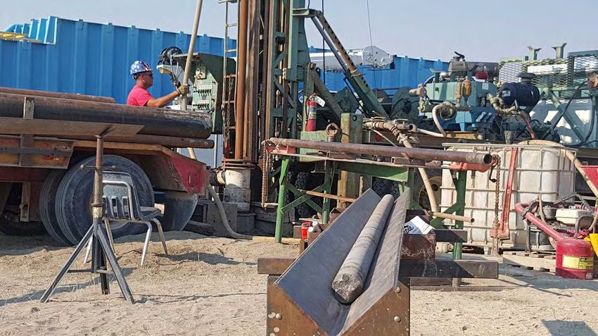
Cover: U.S. Geological Survey hydrologic technician pulling drill core from borehole
TAN-2312 at the Idaho National Laboratory, Idaho. Photograph by Brian V. Twining, U.S.
Geological Survey, August 3, 2017.
Completion Summary for Borehole
TAN-2312 at Test Area North, Idaho
National Laboratory, Idaho

By Brian V. Twining, Roy C. Bartholomay, and Mary K.V. Hodges

DOE/ID-22247
Prepared in cooperation with the U.S. Department of Energy

Scientific Investigations Report 2018–5118

U.S. Department of the Interior
U.S. Geological Survey
U.S. Department of the Interior
RYAN K. ZINKE, Secretary

U.S. Geological Survey
James F. Reilly II, Director

U.S. Geological Survey, Reston, Virginia: 2018

For more information on the USGS—the Federal source for science about the Earth, its natural and living
resources, natural hazards, and the environment—visit https://www.usgs.gov or call 1–888–ASK–USGS.
For an overview of USGS information products, including maps, imagery, and publications,
visit https://store.usgs.gov.

Any use of trade, firm, or product names is for descriptive purposes only and does not imply endorsement by the
U.S. Government.

Although this information product, for the most part, is in the public domain, it also may contain copyrighted materials
as noted in the text. Permission to reproduce copyrighted items must be secured from the copyright owner.

Suggested citation:
Twining, B.V., Bartholomay, R.C., and Hodges, M.K.V., 2018, Completion summary for borehole TAN-2312 at Test Area
North, Idaho National Laboratory, Idaho: U.S. Geological Survey Scientific Investigations Report 2018-5118 (DOE/
ID-22247), 29 p., plus appendixes, https://doi.org/10.3133/sir20185118.

ISSN 2328-0328 (online)
iii

Contents
Abstract............................................................................................................................................................1
Introduction.....................................................................................................................................................2
      Purpose and Scope...............................................................................................................................2
      Hydrogeologic Setting..........................................................................................................................2
Previous Investigations.................................................................................................................................5
Drilling and Borehole Construction Methods............................................................................................6
      Drilling Techniques and Equipment....................................................................................................6
      Detailed Drilling Activity.......................................................................................................................6
Geologic and Geophysical Data...................................................................................................................9
      Geology..................................................................................................................................................10
      Geophysical Logs.................................................................................................................................11
            Natural Gamma Logs..................................................................................................................11
            Caliper Logs.................................................................................................................................11
            Neutron Logs...............................................................................................................................11
            Gamma-Gamma Dual Density Logs.........................................................................................14
            Fluid Logs.....................................................................................................................................14
            Electric Logs................................................................................................................................14
            Acoustic Televiewer Logs.........................................................................................................14
            Electromagnetic Flow Meter Logs...........................................................................................15
            Gyroscopic Deviation Survey...................................................................................................15
Aquifer Test....................................................................................................................................................17
      Aquifer-Test Procedures....................................................................................................................17
      Analysis of Aquifer-Test Data............................................................................................................17
      Hydraulic Property Estimates............................................................................................................19
Water-Sample Collection.............................................................................................................................21
      Sample Collection Methods...............................................................................................................21
      Analytical Methods.............................................................................................................................21
      Guidelines for Interpretation of Analytical Results........................................................................21
            Inorganic Chemistry Data..........................................................................................................23
            Organic Chemistry Data.............................................................................................................23
            Stable Isotope Data....................................................................................................................24
            Radiochemical Data...................................................................................................................24
Summary........................................................................................................................................................24
References Cited..........................................................................................................................................25
Appendixes....................................................................................................................................................29
      Appendix 1. Material Safety Data Sheets for Drilling Mud...........................................................29
      Appendix 2. Driller Log for TAN-2312................................................................................................29
      Appendix 3. Core Logs and Photographs for Borehole TAN-2312...............................................29
      Appendix 4. Archive Approval Memo...............................................................................................29
iv
Figures
1. Map showing location of selected facilities at the Idaho National Laboratory, Idaho......3
2. Map showing location of well TAN-2312 and selected monitor wells, Test Area
North, Idaho National Laboratory, Idaho...................................................................................4
3. Diagram and graphs showing iIdealized typical olivine tholeiite pahoehoe basalt flow..5
4. Diagram and photographs showing HQ-size coring system similar to one used for
coring. HQ refers to core rod sizing (drill-bit size about 3.8-in. outer diameter).................7
5. Diagram showing final constructed well TAN-2312, Test Area North, Idaho National
Laboratory, Idaho...........................................................................................................................8
6. Geophysical logs run from total depth to land surface and lithologic logs described
from cores, video logs, and geophysical logs for borehole TAN-2312, Test Area
North, Idaho National Laboratory, Idaho.................................................................................12
7. Expanded geophysical and lithologic logs with focus on depths 240–525 feet below
land surface for borehole TAN-2312, Test Area North, Idaho National Laboratory,
Idaho..............................................................................................................................................13
8. Diagrams showing gyroscopic deviation data collected for borehole TAN-2312, Test
Area North, Idaho National Laboratory, Idaho.......................................................................16
9. Idealized schematic showing pressure sensor(s) and pump placements during the
aquifer test at well TAN-2312, Test Area North, Idaho National Laboratory, Idaho.........17
10. Graphs showing barometric pressure, air temperature, and discharge rate
measured during the aquifer test in well TAN-2312, Test Area North, Idaho National
Laboratory, Idaho.........................................................................................................................18
11. Graph showing aquifer test data for well TAN-2312, Test Area North, Idaho National
Laboratory, Idaho.........................................................................................................................20
Tables
1. Location and completion information for well TAN-2312, Test Area North, Idaho
National Laboratory, Idaho...........................................................................................................9
2. Summary of geophysical and video log data collected from borehole TAN-2312,
Test Area North, Idaho National Laboratory, Idaho..............................................................10
3. Gyroscopic deviation data from processed survey for borehole TAN-2312, Idaho
National Laboratory, Idaho.........................................................................................................16
4. Comparison of transmissivity values estimated from aquifer tests conducted at
wells within the vicinity of well TAN-2312, Idaho National Laboratory, Idaho. ................20
5. Concentrations of selected chemical and radiochemical constituents in water from
well TAN-2312, Test Area North, Idaho National Laboratory, Idaho...................................22
5. Concentrations of selected chemical and radiochemical constituents in water from
well TAN-2312, Test Area North, Idaho National Laboratory, Idaho...................................23v
Conversion Factors
U.S. customary units to International System of Units
Multiply By To obtain
Length
inch (in.) 2.54 centimeter (cm)
foot (ft) 0.3048 meter (m)
mile (mi) 1.609 kilometer (km)
Volume
gallon (gal) 3.785 liter (L)
cubic foot (ft3) 28.32 cubic decimeter (dm3)
cubic foot (ft3) 0.02832 cubic meter (m3)
liter (L) 33.82 ounce, fluid (fl. oz)
Flow rate
foot per minute (ft/min) 0.3048 meter per minute (m/min)
foot per day (ft/d) 0.3048 meter per day (m/d)
gallon per minute (gal/min) 0.06309 liter per second (L/s)
Pressure
atmosphere, standard (atm) 101.3 kilopascal (kPa)
pound per square inch (lb/in2) 6.895 kilopascal (kPa)
Radioactivity
picocurie per liter (pCi/L) 0.037 becquerel per liter (Bq/L)
Specific capacity
gallon per minute per foot [(gal/min)/ 0.2070 liter per second per meter [(L/s)/m]
ft)]
Hydraulic conductivity
foot per day (ft/d) 0.3048 meter per day (m/d)
Hydraulic gradient
foot per mile (ft/mi) 0.1894 meter per kilometer (m/km)
Transmissivity*
foot squared per day (ft2/d) 0.09290 meter squared per day (m2/d)
Temperature in degrees Celsius (°C) may be converted to degrees Fahrenheit (°F) as follows:
°F=(1.8×°C)+32.
Supplemental Information
*Transmissivity: The standard unit for transmissivity is cubic foot per day per square foot times
foot of aquifer thickness [(ft3/d)/ft2]ft. In this report, the mathematically reduced form, foot
squared per day (ft2/d), is used for convenience.
Specific conductance is given in microsiemens per centimeter at 25 degrees Celsius (µS/cm at
25 °C).
Concentrations of chemical constituents in water are given either in milligrams per liter (mg/L)
or micrograms per liter (µg/L).vi
Datums
Vertical coordinate information is referenced to the National Geodetic Vertical Datum of 1929
(NGVD 29).
Horizontal coordinate information is referenced to the North American Datum of 1927 (NAD 27).
Altitude, as used in this report, refers to distance above the vertical datum.
Abbreviations
ATR Complex Advanced Test Reactor Complex (formerly RTC, Reactor Technology
Complex and TRA, Test Reactor Area)
API American Petroleum Institute
BLS below land surface
CFA Central Facilities Area
CPS counts per second
CTF Contained Test Facility
DLDQ detection limit by DQCALC
DOE U.S. Department of Energy
DQCALC detection and quantitation calculation
EMFM electromagnetic flow meter
EPA Environmental Protection Agency
ESRP eastern Snake River Plain
INL Idaho National Laboratory
INTEC Idaho Nuclear Technology and Engineering Center
MFC Materials and Fuels Complex
MRL minimum reporting level
N nitrogen
NRF Naval Reactors Facility
NWQL National Water Quality Laboratory (USGS)
P phosphorus
HQcore rod sizing
RESL Radiological and Environmental Sciences Laboratory (DOE)
RSIL Reston Stable Isotope Laboratory
RWMC Radioactive Waste Management Complex
s sample standard deviation
TAN Test Area North
USGS U.S. Geological Survey
VOC volatile organic compoundCompletion Summary for Borehole TAN-2312 at
Test Area North, Idaho National Laboratory, Idaho
By Brian V. Twining, Roy C. Bartholomay, and Mary K.V. Hodges
Abstract texture for borehole TAN-2312 generally was described as
aphanitic, phaneritic, and porphyritic. Basalt flows varied from
In 2017, the U.S. Geological Survey, in cooperation highly fractured to dense with high to low vesiculation.
with the U.S. Department of Energy, drilled and constructed Geophysical and borehole video logs were collected after
borehole TAN-2312 for stratigraphic framework analyses and core drilling and after final construction at borehole TAN-
long-term groundwater monitoring of the eastern Snake River 2312. Geophysical logs were examined synergistically with
Plain aquifer at the Idaho National Laboratory in southeast available core material to suggest zones where groundwater
Idaho. The location of borehole TAN-2312 was selected flow was anticipated. Natural gamma log measurements were
because it was downgradient from TAN and believed to be used to assess sediment layer thickness and location. Neutron
the outer extent of waste plumes originating from the TAN and gamma-gamma source logs were used to identify fractured
facility. Borehole TAN-2312 initially was cored to collect areas for aquifer testing. Acoustic televiewer logs, fluid logs,
continuous geologic data, and then re-drilled to complete and electromagnetic flow meter results were used to identify
construction as a monitor well. The final construction for fractures and assess groundwater movement when compared
borehole TAN-2312 required 16- and 10-inch (in.) diameter against neutron measurements. Furthermore, gyroscopic
carbon-steel well casing to 37 and 228 feet below land deviation measurements were used to measure horizontal and
surface (ft BLS), respectively, and 9.9-in. diameter open-hole vertical displacement for borehole TAN-2312.
completion below the casing to 522 ft BLS. Depth to water After construction of borehole TAN-2312, a single-well
is measured near 244 ft BLS. Following construction and aquifer test was completed September 27, 2017, to provide
data collection, a temporary submersible pump and water- estimates of transmissivity and hydraulic conductivity.
level access line were placed near 340 ft BLS to allow for Estimates for transmissivity and hydraulic conductivity
aquifer testing, for collecting periodic water samples, and for were 1.51×102 feet squared per day and 0.23 feet per day,
measuring water levels. respectively. During the 220-minute aquifer test, well TAN-
Borehole TAN-2312 was cored continuously, starting 2312 had about 23 ft of measured drawdown at sustained
at the first basalt contact (about 37 ft BLS) to a depth of pumping rate of 27.2 gallons per minute. The transmissivity
568 ft BLS. Not including surface sediment (0–37 ft), and hydraulic conductivity estimates for well TAN-2312 were
recovery of basalt and sediment core at borehole TAN-2312 lower than the values determined from previous aquifer tests
was about 93 percent; however, core recovery from 170 to in other wells near Test Area North.
568 ft BLS was 100 percent. Based on visual inspection of Water samples were analyzed for cations, anions, metals,
core and geophysical data, basalt examined from 37 to 568 nutrients, volatile organic compounds, stable isotopes, and
ft BLS consists of about 32 basalt flows that range from radionuclides. Water samples for most of the inorganic
approximately 3 to 87 ft in thickness and 4 sediment layers constituents showed concentrations near background levels
with a combined thickness of approximately 76 ft. About for eastern regional groundwater. Water samples for stable
2 ft of total sediment was described for the saturated zone, isotopes of oxygen, hydrogen, and sulfur indicated some
observed from 244 to 568 ft BLS, near 296 and 481 ft BLS. possible influence of irrigation on the water quality. The
Sediment described for the saturated zone were composed of volatile organic compound data indicated that this well had
fine-grained sand and silt with a lesser amount of clay. Basalt some minor influence by wastewater disposal practices at Test
Area North.2 Completion Summary for Borehole TAN-2312 at Test Area North, Idaho National Laboratory, Idaho
Introduction coring, construction, geophysical logging, aquifer testing, and
water sampling for borehole TAN-2312. General lithologic
The U.S. Geological Survey (USGS), in cooperation with descriptions of the drill core for borehole TAN-2312 are
the U.S. Department of Energy (DOE), has collected borehole provided and detailed descriptions are included in appendixes
information at the Idaho National Laboratory (INL) since 1–3. This report presents a comprehensive suite of water
1949 to provide baseline data concerning the migration and samples analyzed for inorganic, organic, stable isotopes, and
disposition of radioactive and chemical wastes in the eastern radionuclide constituents, and results.
Snake River Plain (ESRP) aquifer. The USGS is refining
numerical models for the movement of groundwater and Hydrogeologic Setting
contaminants in the ESRP aquifer. Additional hydrogeologic
and borehole information downgradient from Test Area The INL is in the west-central part of the ESRP (fig. 1).
North (TAN) is needed to understand groundwater flow for The ESRP is a northeast-trending structural basin about 200
ongoing studies (fig. 1). Borehole TAN-2312 was located as a miles (mi) long and 50–70 mi wide. Formation of the ESRP
downgradient well for monitoring radiochemical and chemical was caused by the passage of the North American tectonic
constituents that were previously discharged from TAN. plate over the Yellowstone Hot Spot (Pierce and Morgan,
Geologic data along with hydraulic properties (transmissivity 1992). The ESRP is subject to continuing basaltic volcanism
and hydraulic conductivity) are needed to define groundwater and subsidence because disruption to the crust resulted
movement as it relates to contaminant transport of waste in increased heat flow (Blackwell and others, 1992) and
plumes at TAN. emplacement of a dense, mid-crustal sill (Shervais and others,
The week of July 17, 2017, the USGS mobilized 2006). The subsiding ESRP basin was filled with interbedded
equipment to TAN to begin drilling for borehole TAN- terrestrial sediments and Pleistocene to late Pliocene basalt,
2312 (fig. 2). Borehole TAN-2312 was cored from the first 0.6–1.2 mi thick (Whitehead, 1992). The basaltic rocks and
basalt contact to a depth of 568 ft below land surface (BLS) sedimentary deposits make up the ESRP aquifer.
and constructed as a monitor well at completion of coring. The ESRP is composed mostly of olivine tholeiite basalt
Borehole TAN-2312 was constructed with 16-in. diameter flows, which erupted as tube-fed, inflated, pahoehoe flows
surface casing to 37 ft BLS (first basalt contact), 10-in. well that make up more than 85 percent of the subsurface volume
casing to 228 ft BLS, and 9.9-in. open-hole to 522 ft BLS. The of the ESRP at the INL (Anderson and Liszewski, 1997).
section of borehole from 522 to 568 ft BLS was not re-drilled Figure 3 includes a diagram of a lobe of a tube-fed pahoehoe
and borehole video, collected after construction, shows that ESRP basalt flow, showing cooling fractures that develop
section of borehole had filled with drill cuttings. Drilling and perpendicular to the exterior surfaces, vesicle zones and
construction were completed September 20, 2017, for aquifer sheets, pipe vesicles, interior mega vesicles, and a diktytaxitic
testing and groundwater sampling. to massive core. The distribution of basalt flows is controlled
Various data were collected throughout the drilling by topography, rate of effusion, and duration of eruption. Near-
process and compiled within this report. Geophysical data and vent flows are thinner than distal flows, and accumulations of
downhole video were collected and examined to confirm open thin flows have a larger volume of high conductivity zones
borehole conditions and identify areas of fractured and dense than the same volume of thick flows (Anderson and others,
basalt. After construction, aquifer testing was done for well 1999).
TAN-2312 on September 27, 2017. Additionally, an extensive The part of the Snake River Plain aquifer that underlies
suite of groundwater samples was collected after purging to the ESRP is one of the most productive aquifers in the United
examine water chemistry. States (U.S. Geological Survey, 1985, p. 193). Groundwater
in the ESRP aquifer generally moves from northeast to
southwest, eventually discharging to springs along the
Purpose and Scope Snake River downstream of Twin Falls, Idaho—about 100
The purpose of this study is to better understand the mi southwest of the INL (Whitehead, 1992). Water moves
hydrogeology in the northern part of the INL, specifically at through basalt fracture zones at the tops, bases, and sides
TAN. Borehole TAN-2312 was located downgradient from the of basalt flows. Infiltration of surface water, groundwater
TAN facility; data collected will be used to characterize both pumping, geologic conditions, and seasonal fluxes of recharge
radiochemical and chemical waste plumes that are currently and discharge locally affect the movement of groundwater
undergoing treatment. Geologic, geophysical, and aquifer (Garabedian, 1986). Recharge to the ESRP aquifer is primarily
test data were collected and analyzed to determine lithologic from infiltration of applied irrigation water, streamflow,
and hydraulic properties. Additionally, water samples were precipitation, and groundwater inflow from adjoining
collected and analyzed to provide water-quality data after mountain drainage basins (Ackerman and others, 2006).
construction. This report presents results of the drilling,Introduction 3
113°00' 112°30'
BITTERROOT
RANGE
Bir
EXPLANATION
ch
44° Mountain ranges
00'
Cre
Rhyolite domes
ek
Approximate location of mountain front
Idaho National Laboratory facility and identifiers
RWMC Radioactive Waste Management Complex
LE
ATR Advanced Test Reactor
MH
INTEC Idaho Nuclear Technology and Engineering Center
IR
CFA Central Facilities Area
Lit
A
NRF Naval Reactors Facility tle Mud
NG
TAN Test Area North Lake
E
MFC Materials and Fuels Complex See Figure 2
Mud
Lake Terreton
Lo
TAN
st
Birch Creek 33
Ri sinks
ve
r
Howe
LO
ST
Big Lost River
Sinks and
RI
VE
Playas
RR
ANG
E
Arco NRF
Bi 26 20
g ATR
Complex MFC
Lo INTEC
st
Riv 20
er
CFA
43°
30'
RWMC
Spreading East
areas Butte
Middle
Butte
Atomic
City
IDAHO Eastern Snake
River Plain
Idaho National 26
Laboratory Big Southern
Boise Butte
Idaho
0 5 10 15 MILES
Falls
Pocatello 0 5 10 15 KILOMETERS
Twin Falls
Base from U.S. Geological Survey digital data, 1:24,000 and 1:100,000
Universal Transverse Mercator projection, Zone 12
Datum is North American Datum of 1927
Figure 1. Location of selected facilities at the Idaho National Laboratory, Idaho.
tac18-1243_fig 014 Completion Summary for Borehole TAN-2312 at Test Area North, Idaho National Laboratory, Idaho
112°45’ 112°44’ 112°43’ 112°42’
ANP-6
Bi
rc
hC
re
ek
CTF
TAN-2271
43° TAN-2
51’
TAN-CH2
TAN
TAN Disposal
TAN-1
TAN-2272 ANP-3 USGS-24
Fire
hydrant
TAN-CH1
43°
50’
GIN-05
EXPLANATION
GIN-02
TAN-CH2 Local well location and identifier TAN-2312
TAN-2312 Local well location identifier for well
drilled for this study
Water supply well used for drill water
TAN Test Area North (Idaho National
Laboratory facility) 0 0.5 1 MILE
CTF Contained Test Facility (Idaho
National Laboratory facility) 0 0.5 1 KILOMETER
Figure 2. Location of well TAN-2312 and selected monitor wells, Test Area North, Idaho National
Laboratory, Idaho.
Throughout the INL, the March–May 2015 water-table mi); the average is about 4 ft/mi (Bartholomay and others,
altitude ranged from about 4,560 to 4,410 ft (Bartholomay 2017, fig. 9). Horizontal flow velocities of 2–20 feet per day
and others, 2017, fig. 9); at borehole TAN-2312, the altitude (ft/d) have been calculated based on the movement of various
of the water table is about 4,544 ft. Depth to water ranges chemical and radiochemical constituents in different areas
from about 200 ft BLS in the northern part of the INL to of the ESRP aquifer at the INL (Robertson and others, 1974;
more than 900 ft BLS in the southeastern part; depth to water Mann and Beasley, 1994; Cecil and others, 2000; Busenberg
measured in borehole TAN-2312 is about 244 ft BLS. Most and others, 2001). These flow rates equate to a travel time
groundwater moves through the upper 200–800 ft of basaltic of about 70–700 years for water beneath the INL to travel to
rocks (Mann, 1986, p. 21). The estimated transmissivity springs that discharge at the terminus of the ESRP aquifer near
for the upper part of the ESRP aquifer is 1.1–760,000 feet Twin Falls, Idaho (fig. 1). Localized tracer tests at the INL
squared per day (ft2/d) reported by Ackerman (1991, p. 30) have shown vertical and horizontal transport rates as high as
and Bartholomay and others (1997, table 3). The hydraulic 60 and 150 ft/d, respectively (Nimmo and others, 2002; Duke
gradient at the INL ranges from 2 to 10 feet per mile (ft/ and others, 2007).
TAC18-1243_fig 02Previous Investigations 5
Pahoehoe
lobe surface Fracture frequency Percent volume Vesicle characteristics
Highly
Unfractured fractured Vesicle Mean diameter, in inches
0 1 2 3 4 0 20 40 0 1 2 3
Fractured
upper crust
(most Vesicle zone
conductive)
Fracture
Vesicle zone
Vesicle zone
Diktytaxitic
to massive
interior Vesicle sheet
(least Mega vesicle
conductive)
Vesicle cylinder
Lower crust
(moderately
conductive)
Pipe vesicle
Vesicle zone
Figure 3. Idealized typical olivine tholeiite pahoehoe basalt flow (modified from Self and others, 1998, fig. 3, p. 90). The basalt
flow is divided into three sections based on vesicle characteristics and fracture frequency. Hydraulic conductivity is highest for
the fractured upper crust, moderate for the lower crust, and lowest for the diktytaxitic to massive interior. The photograph of the
pahoehoe lobe surface is courtesy of Scott Hughes, Emeritus Professor, Idaho State University, Pocatello, Idaho.
Previous Investigations through gyroscopic and magnetic methods and presents
correction factors for water-level observations at well sites at
The USGS INL Project Office has been involved with and near the INL.
providing completion reports for special studies addressing Twining and others (2016) summarizes the data
drilling and testing of wells for the ESRP aquifer at the INL. collected during the drilling, construction, and testing
USGS INL Project Office has also been involved with the of boreholes TAN-2271 and TAN-2272. Data collected
collection and interpretation of geophysical data collected include: geophysical logging data, aquifer testing data, and
throughout the INL and surrounding area. A comprehensive groundwater sampling data. The collection methods and
listing of publications by the USGS is available through analysis described for boreholes TAN-2271 and TAN-2272
weblink—https://www.usgs.gov/centers/id-water/science/ are very similar methods and analysis used for borehole
publications-idaho-national-laboratory?qt-science_center_ TAN-2312. The reported data were provided to DOE and the
objects=0#qt-science_center_objects. supporting contractor for ongoing monitoring at the TAN
Twining (2016) investigates borehole deviation data facility.
for wells constructed within the ESRP aquifer. This well
completion summary report examines deviation data collected
tac18-1243_fig 036 Completion Summary for Borehole TAN-2312 at Test Area North, Idaho National Laboratory, Idaho
Drilling and Borehole Construction to keep the borehole straight and plumb while reaming. Air
and water were the primary fluids while reaming; however,
Methods Baroid® Quik-Foam® (foam) was introduced to improve
cutting returns to surface, when necessary (appendix 1).
Drilling, well construction, and hydraulic testing by Pressurized air and water were used to complete
the USGS took place between July 25, 2017, and September HQ-coring for borehole TAN-2312 from about 37 to 568
27, 2017. All activities were in accordance with the USGS ft BLS. Water and air usage ranged from 2 to 5 gallons per
INL Site Safety Plan (Roy Bartholomay, U.S. Geological minute (gal/min), with air pressures ranging from 100 to 350
Survey, written commun., December 16, 2016) and the lb/in2. Core drilling fluid from land surface to about 244 ft
INL Environmental Checklist requirements. Prior to BLS was disposed to the ground; however, drill fluid returns
drilling startup, construction barriers were established and from about 244 to 568 ft BLS were diverted to frac-tanks for
a job-site, pre-job, safety briefing was held July 25, 2017. later disposal. Core drilling for borehole TAN-2312 generated
Regular equipment inspections and safety discussions were approximately 4,000 gal of drill fluid returns.
documented and weekly drilling updates were distributed by Pressurized air, water, and drill foam were used during
email during the project. Safety Data Sheets for chemicals reaming 15-in., 13-in., and 9.9-in. diameter sections in
used during drilling are included in appendix 1. A summary borehole TAN-2312. Drilling fluid was continuously injected
of driller notes along with daily activity are included in at rates of about 2–4 gal/min. Reaming was completed and
appendix 2. well casing placed down to 228 ft BLS before core drilling
Where drilling was done downgradient of the TAN into the aquifer. Borehole TAN-2312 was constructed as
facility (fig. 1), State regulatory agencies required drill fluid open hole (9.9-in. diameter) between 228 and 522 ft BLS,
returns to be diverted to holding tanks (frac-tanks) after 244 see fig. 5. Drill fluid and cutting material for the 9.9-in.
ft BLS, approximate depth to ESRP aquifer. Drill cuttings and diameter borehole were diverted to 21,000 gal frac-tanks.
fluid returns, diverted to frac-tanks, were handled by Waste Approximately 38,000 gal of fluid returns were generated
Generator Services at the INL for disposal. Water used during during reaming and approximately 3,000 gal of water were
coring, reaming, and well construction was supplied from a generated during development of borehole TAN-2312 from
fire hydrant located at TAN (fig. 2). 244 to 522 ft BLS.
Drilling Techniques and Equipment Detailed Drilling Activity
Borehole TAN-2312 was continuously cored from about Drilling at borehole TAN-2312 started July 25, 2017,
37 to 568 ft using a Christensen™ CS 1500 rotary drilling rig using a modified tri-cone to drill to the first basalt. After
and HQ-size coring system, where HQ refers to core rod sizing removing the bit assembly, 16-in. diameter well casing was
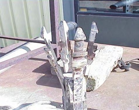
(drill-bit size about 3.8-in. diameter). The core system was placed to a depth of 37 ft on July 26, 2017, and about 5 ft3 of
setup with carbide and diamond core bits, core catchers, and granular bentonite casing seal was set behind the casing on
latch assembly for core retrieval (fig. 4). Core was retrieved in July 31, 2017. Once the surface casing was in the ground, the
10-ft sections using a four-part wireline latching mechanism SD-300 drill rig was changed out for the CS-1500 core rig.
(quadlatch) at the top of the core-barrel assembly. After Core drilling (HQ-size) in borehole TAN-2312 was done
removal from the borehole, core was marked for orientation in two stages, stage 1 involved coring from about 37 to 227
and depth in the field before boxing. Once cleared, the cores ft BLS (August 1–3, 2017) and stage 2 included core drilling
where taken to CFA-663 to be photographed and archived at from 228 to 568 ft BLS (August 17–30, 2017). Reaming for
the INL Lithologic Core Storage Library (appendix 3), which borehole TAN-2312 was completed following coring for both
is operated by the USGS at the Central Facilities Area (CFA) stage 1 (unsaturated zone) and stage 2 (saturated zone).
(fig. 1). On completion of stage 1 core drilling, borehole TAN-
Rotary tri-cone drilling, downhole hammer (DHH) 2312 was reamed to 15-in. diameter from 37 to 84 ft BLS
drilling, and setting well casing segments were performed on August 7, 2017 (appendix 2). Afterwards, temporary well
using a GEFCO™ SD-300. The rig was initially used to tri- casing (14-in. diameter) was placed down to 84 ft BLS to hold
cone drill and drive 16-in. diameter casing to the first basalt back an unstable sediment layer that existed from about 52
contact in borehole TAN-2312. Additionally, the SD-300 to 82 ft BLS (appendix 2). The 14-in. diameter well casing
drill rig was used to re-drill (ream) 15-in, 13-in., and 9.9-in. was placed as a precautionary measure to prevent potential
diameter borehole sections during the construction phase. problems when reaming to 13-in. diameter. The 14-in.
Spiral stabilizers, sized to the drill bit diameter, were used diameter well casing was removed August 14, 2017.Drilling and Borehole Construction Methods 7
A. Quadlatch assembly
Quadlatch
finger
Tension
spring
Pivot
bearing B. Core catcher with inner barrel
Outer core Inner barrel
barrel
Core catcher
Bearing
assembly
Drill rod
Check ball
C. Core bit
Inner core Drill rod
barrel
Core
catcher
Core bit
Modified from Christensen Products (1997).
Figure 4. HQ-size coring system similar to one used for coring. HQ refers to core rod sizing (drill-bit size about 3.8-in. outer
diameter).
tac18-1243_fig 048 Completion Summary for Borehole TAN-2312 at Test Area North, Idaho National Laboratory, Idaho
TAN-2312
Top view
Well ID:
434939112421601 16-in. schedule 40-
Site ID: carbon steel casing 10-in. schedule 40-
carbon steel casing
Notes: Well configuration for aquifer test
September 27, 2017; ft BLS, foot below land
surface; in., inch
Cement Pad
0 0
EXPLANATION 16-in. casing set to 37 ft BLS
18-in. borehole drilled with
Bentonite casing seal tri-cone bit down from 0 to 37 ft
Cement BLS
15-in. borehole drilled with
button-bit down hole hammer
from 37 to 84 ft BLS
13-in. borehole drilled with
button-bit down hole hammer
100 from 84 to 228 ft BLS 100
10-in. casing set to 228 ft BLS
Bentonite casing seal set
from 0 to 228 ft BLS
200 200
Water level - 244.40 ft. BLS
measured 9/27/2017 at 10:19AM 1-in. stainless steel water level
Depth, in feet below land surface
Depth, in feet below land surface
taken before aquifer test access line set to 280 ft. BLS
1-in. stainless steel water level
access line set to 338 ft. BLS
9.87-in. open borehole drilled
from 228 to 522 ft. BLS
300 300
4-in. pump assembly
(5-horsepower pump) set near
340 ft. BLS
400 400
500 500
Total depth about 522 ft. BLS
3.8-in. corehole filled with cutting
material 522 to 568 ft. BLS
600 600
Figure 5. Final constructed well TAN-2312, Test Area North, Idaho National Laboratory, Idaho.
tac18-1243_fig 05Geologic and Geophysical Data 9
Starting August 9, 2017, borehole TAN-2312 was reamed Table 1. Location and completion information for well TAN-2312,
to 13-in. diameter from 84 to 228 ft BLS, 1 ft past where core Test Area North, Idaho National Laboratory, Idaho.
drilling stopped. Afterwards, 10-in. diameter well casing was
[Location of well is shown in figure 2. Local name: Local well identifier used
placed down to 228 ft BLS and the borehole annular space in this study. Site identifier: Unique numerical identifier used to access well
was filled in with approximately 42 ft3 of bentonite casing seal data (http://waterdata.usgs.gov/nwis). Longitude, Latitude, and Measurement
on August 15, 2017 (fig. 5). The bentonite casing seal was point elevation: Survey taken at brass survey marker (brass cap) located
installed dry; Izbiki and others (2000) have shown through adjacent to well head on cement pad. Aquifer thickness: The altitude of the
base of the aquifer as interpreted from geophysical surveys (Whitehead,
repeated neutron logging that bentonite hydrates and forms
1992) subtracted from the measured depth to water (altitude of water table).
an effective low-permeability seal after installation within Open borehole diameter: Based on drilled diameter of open borehole interval.
the borehole. Frequent sounding measurements along with TAN-2312: NAD 27, North American Datum of 1927; NGVD 29, National
approximated material volume calculations were used to Geodetic Vertical Datum of 1929; AMSL, above mean sea level; BLS, below
confirm accurate backfill material placement. land surface; ft, foot; in., inch]
The second stage of coring, followed by reaming,
required fluids to be placed in frac-tanks. Core drilling was Local name TAN-2312
halted at a depth of 568 ft BLS, stopping in dense basalt. Site identifier 434939112421601
Reaming was completed from 228 to 522 ft BLS (September Longitude 112°42'16.6" (NAD 27)
6–20, 2017). Reaming was halted at 522 ft BLS, completing Latitude 43°49'39.7" (NAD 27)
the well about 278 ft into the ESRP aquifer (244 to 522 ft Measurement point elevation 4,796 ft (NGVD 29) AMSL
BLS). Near 500 ft BLS, reaming to 9.9-in. diameter started to (approximate)
slow because of fluid pressure over the DHH bit. At a depth of Aquifer thickness 700 ft
518 ft BLS, drilling was halted and the DHH was changed out Completion depth 522 ft BLS
for a tri-cone bit assembly on August 19, 2017. Reaming using Drill depth 568 ft BLS
a 9.9-in. diameter tri-cone bit assembly was resumed from Open borehole diameter 9.9 in.
518 to 522 ft BLS; however, progress was very slow through Casing diameter 10 in.
dense basalt sections. After reaming and before removing Top of open borehole 228 ft BLS
the tri-cone assembly, borehole TAN-2312 was developed by Bottom of open borehole 522 ft BLS
blowing air to develop from the bottom of the borehole, this Depth to water 244.40 ft BLS, measured
generated approximately 3,000 gal of water. The afternoon of September 27, 2017, at
August 20, 2017, drilling was stopped and the tri-cone drilling 10:19 a.m.
assembly was removed from borehole TAN-2312 to allow it
to sit and clear up over the weekend. A borehole video, taken
August 25, 2017, confirmed the completion depth of 522 ft
BLS and that the cored section, from 522 to 568 ft BLS, was
Geologic and Geophysical Data
filled with drill cutting material and was not accessible (fig. 5,
Geologic data were collected and analyzed from
appendix 2).
core material to provide rock and sediment properties;
On September 27, 2017, borehole TAN-2312 was
additionally, geologic and hydrologic data, including geologic
configured with a temporary Grundfos™ 5-horsepower
contacts, were interpreted from geophysical logs collected
SS submersible pump, 4-wire (7 gauge) pump wire, 1-in.
and analyzed for borehole TAN-2312. Geophysical logs
diameter SS discharge line, and 1-in. diameter SS water-level
provide a complete and continuous formation representation
line placed (fig. 5). The submersible pump intake was set
adjacent to the well bore and offer more consistency when
near 340 ft BLS for aquifer testing and well development,
selecting depths for geologic contacts, when core recovery
and the 1-in. diameter measuring line was installed down to
is sometimes incomplete. Rock and sediment core recovered
about 280 ft BLS. The final construction of borehole TAN-
from borehole TAN-2312 was photographed and labeled to
2312 (fig. 5) includes (1) 16-in. diameter carbon steel casing
provide detailed lithologic descriptions from 37 to 568 ft BLS.
extending from 3.5 ft above land surface to 37 ft BLS, (2)
Core photographs and lithologic descriptions are presented in
10-in. diameter threaded carbon steel casing extending from
appendix 3.
2.8 ft above land surface to 228 ft BLS, and (3) 9.9-in. inside
diameter open borehole from 228 to 522 ft BLS. Surface
completion includes a 4-ft diameter concrete pad complete
with a brass survey marker, and a locking wellhead (table 1).10 Completion Summary for Borehole TAN-2312 at Test Area North, Idaho National Laboratory, Idaho
The wireline geophysical logging equipment, operated table 2. Geophysical data are available upon request through
by the USGS, was used to collect data in borehole TAN- the USGS INL Project Office or through weblink—https://
2312. Geophysical data were collected during various stages webapps.usgs.gov/GeoLogLocator/#!/.
of drilling and construction; additionally, video data were
collected and used to evaluate the condition of borehole TAN-
2312. Geophysical log data included: natural gamma, neutron, Geology
gamma-gamma dual density, acoustic caliper, temperature,
The land surface at borehole TAN-2312 is sparsely
specific conductance, electromagnetic flow meter (EMFM),
vegetated loess. Surface sediment was not cored, but
acoustic televiewer, and gyroscopic deviation. Geophysical
described in drill cuttings as an unconsolidated mixture of
log data were collected and saved as electronic files in the
poorly developed soil consisting of fine to coarse sand to the
form of physical measurement and depth and processed using
first basalt contact, near 37 ft BLS. Surface materials were
WellCAD™ software. Geophysical data, once processed, were
described from drill cuttings observed while drilling and
used to suggest geologic and hydrologic characteristics. The
driving 16-in. diameter surface casing (appendix 2).
geophysical and video log data collected are summarized in
Table 2. Summary of geophysical and video log data collected from borehole TAN-2312, Test Area North, Idaho National
Laboratory, Idaho.
[Geophysical data presented in this report were collected using one or more of the following logging tools listed below. Log type: Description of geophysical
log trace presented. Tool ID: Century Geophysical Corporation ™ tool number as referenced on web site http://www.century-geo.com/; WC-1750 camera
designed by Aries™ Industry. Depth: Logging depth reported from land surface measurement point. Date and Time: Refers to date and local time the log was
time stamped in month-day-year and hours:minutes. Sensor uncertainty: Uncertainty specfied by tool manufacturer. Comments: explanations where needed.
Abbreviations: ID, Identifier; NA, not applicable; BLS, below land surface; in., inch; ft, foot;
ft/min, foot per minute; gal/min, gallon per minute]
U.S. Geological Survey geophysical logging files
Depth (ft BLS) Sensor
Log type Tool ID Date Time Comments
Top Base uncertainty
Natural Gamma 9057A 0 567 09-05-17 11:07 ±5 percent Run after coring HQ-size (3.8-in.) drill rod set
at 568 ft BLS
Acoustic Caliper 9804C 230 522 09-25-17 11:30 ±0.1 in. Run after reaming to 9.9-in., open hole from
228–522 ft BLS
Neutron 9057A 0 567 09-05-17 11:30 ±5 percent Run after coring HQ-size (3.8-in.) drill rod set
at 568 ft BLS
Gamma-gamma density 0024A 0 566 09-05-17 13:22 ±5 percent Run after coring HQ-size (3.8-in.) drill rod set
at 568 ft BLS
Temperature and specific 9042A 0 521 09-26-17 08:35 ±5 percent Run after reaming to 9.9-in., open hole from
conductance 228–522 ft BLS
Gyroscopic deviation 9095 0 553 09-05-17 11:23 ±0.5 degree Down log, run after coring HQ-size (3.8-in.)
drill rod set at 568 ft BLS
9095 0 553 09-05-17 11:51 ±0.5 degree Up log, run after coring HQ-size (3.8-in.) drill
rod set at 568 ft BLS
Electromagnetic flow 9721 250 500 09-25-17 13:51 ±5 percent Ambient stations - run after reaming to 9.9-in.
meter (EMFM) open hole 228–522 ft BLS
9721 250 513 09-26-17 10:13 ±5 percent Trolling up at 5 ft/min - run after reaming to
9.9-in. open hole 228–522 ft BLS
9721 250 514 09-26-17 11:18 ±5 percent Trolling up at 10 ft/min - run after reaming to
9.9-in. open hole 228–522 ft BLS
Acoustic Televiewer 9804C 0 522 09-25-17 11:30 ±5 percent Run after reaming to 9.9-in., open hole from
228–522 ft BLS
Borehole Video WC-1750 0 522 09-25-17 11:30 ±0.15 in. Run after reaming to 9.9-in., open hole from
228–522 ft BLS - cloudy
WC-1750 225 523 10-10-17 11:30 ±0.15 in. Run after reaming to 9.9-in., open hole from
228–522 ft BLS - mostly clearGeologic and Geophysical Data 11
Excluding surficial sediment (0–37 ft BLS), four borehole TAN-2312 (fig. 6 and appendix 3). Sediment layer
sediment layers were observed between 37 and 568 ft BLS thickness ranges from 37 ft (surface sediment) to less than 2
in borehole TAN-2312 (appendix 3). Including surficial ft and mostly consisted of fine grained sand, silt, and some
sediment, sediment constitutes about 14 percent (77 of 568 ft) clay. Most of the sediment reported in borehole TAN-2312
by volume of borehole TAN-2312. Most of the sediment is present within the unsaturated zone, above 244 ft BLS.
for borehole TAN-2312 was described for the unsaturated Approximately 3 ft of sediment resides in the saturated zone
zone, above 244 ft BLS. Sediment layer(s) described for described at this well location. Fine grained sediment fill,
the saturated zone were minor and makeup a very small described in borehole TAN-2312 fractures, did now show
percentage of the saturated zone. Sediment layers described up in natural gamma traces (fig. 6); however, sediment was
for borehole TAN-2312 consist of fine sand, silt, and clay. described in core material (appendix 3).
Upon inspection of geophysical data, about 32 basalt
flows were observed in borehole TAN-2312 (appendix 3).
Core material presented in appendix 3 confirms location of Caliper Logs
most basalt flows; however, some material was missing and The acoustic caliper log scans the borehole and converts
not all flow contacts were labeled. Basalt textures for borehole the reflected travel time to distance between the sonde and the
TAN-2312 varied between aphanitic, phaneritic, diktytaxitic, borehole wall. The acoustic caliper log uses acoustic transit
and porphyritic. In general, the basalts are medium to dark and velocity data to generate directional caliper in the X and
gray in color. Basalt flows in borehole TAN-2312 ranged in Y directions, noted as ATV X and ATV Y respectively (fig. 7).
thickness from about 3 to 82 ft and varied from massive to The acoustic caliper log generates a continuous profile of the
fractured, with varying degrees of vesiculation. Detailed core borehole diameter as the tool is raised from the bottom of the
descriptions and photographs for borehole TAN-2312 (37–568 borehole. The acoustic caliper tool can detect subtle changes
ft BLS) are included in appendix 3. in borehole diameter, greater than or equal to 0.1-in.
Acoustic caliper logs were collected after reaming
Geophysical Logs borehole TAN-2312 to 9.9 in. (fig. 7) and used to confirm rock
property changes, such as fractured and vesicular to dense
Geophysical data were collected using Century basalt. Acoustic caliper data collected for borehole TAN-2312
Geophysical Corporation™ logging equipment, and the show remnant traces of the drilled HQ-size corehole, drilled
resulting data files were processed using WellCAD™ analytical before reaming (fig. 7). The drilled corehole trace is detected
software. Borehole video logs were recorded using an Aries as noise recorded in the acoustic caliper data. Fractured and
Industry™ WC-1750 downhole color camera. The USGS (or) vesicular zones, identified in caliper logs, correlate with
calibrates geophysical logging equipment annually; logging elevated neutron porosity data and changes in density. Fracture
equipment sensor uncertainty is specified on table 2. A and (or) vesiculated zones are considered the primary water
composite of natural gamma, neutron, and gamma-gamma producing zones where groundwater flow is expected.
dual density along with well design and general lithology from
land surface to completion depth are shown in figure 6.
Neutron Logs
Neutron measurements are a general indicator of
Natural Gamma Logs hydrogen content; when they are combined with natural
Natural gamma logs record gamma radiation emitted by gamma logs for sediment location, they can be used
naturally occurring radioisotopes. The USGS uses these logs to identify perched water. The neutron log records the
at the INL to identify sedimentary layers in boreholes and to continuous measurement of the induced radiation produced by
distinguish between basalt flows that contain varying amounts bombarding surrounding media (casing, formation, and fluid)
of potassium-40. The natural gamma detector measures total with fast neutrons (energies greater than 105 electron volts
gamma radiation without distinguishing between individual from a sealed neutron source, which collide with surrounding
contributions of the various isotopes. atomic nuclei until they are captured (Keys, 1990, section 5,
Natural gamma logs were collected after coring to p. 95). The neutron tool used by the USGS INL Project Office
568 ft BLS, with drill rods placed on the bottom (fig. 6). has an americium/beryllium neutron source and a Helium-3
Excluding surface sediment, the tops of sediment layers detector.
were at approximately 52, 159, 296, and 481ft BLS in12 Completion Summary for Borehole TAN-2312 at Test Area North, Idaho National Laboratory, Idaho
Natural gamma Neutron Gamma-gamma Well completion TAN-2312 Lithology, construction, EXPLANATION
Lithology
(Ci-137) and aquifer test information
GAM(NAT) Neutron (Am/Be-241) Density (SS) TAN-2312 Zero reference top of ground Definition of terms
0 (API) 150 0 (API) 3,000 65,000 (CPS) 160,000 (Depth in feet BLS)
Am/Be-241 -
Porosity Density (LS)
Americium
0 Percent 3,000 0 (CPS) 20,000 Beryllium
0
Note: Lithology (basalt/sediment) contacts API - American
were estimated from natural gamma and Petroleum Institute
25 neutron logs taken 09-05-2017. BLS, below BLS - below land
land surface surface
TAN-2312 Construction CPS - counts per
50 second
* 16-in. casing set to 37 ft. BLS.
* 15-in. drilled hole to 84 ft. BLS Density (SS) - short-
* 13-in. drilled hole 84 to 228 ft. BLS spaced density
75 Density (LS) - long-
* 10-in. casing set to 228 ft. BLS
* 9.9-in. hole drilled from 228 to 522 ft. BLS spaced density
after coring. ft. - feet
100
Gam(Nat) - natural
* HQ-core (3.8-in.) collected from 37 to 568 gamma radiation
ft. BLS beforereaming
125 in. - inches
* 3.8-in. corehole from 522 to 568 ft. BLS
filled in with cutting material (sluff) Neutron - hydrogen
index
150
General Lithology (0 to 228 ft. BLS) Porosity - liquid-filled
* Suface sediment - 0 to 37 ft. BLS porosity
* Basalt - 37 to 52 ft. BLS approximate
175
* Sediment - 52 to 82 ft. BLS Lithology
* Basalt - 82 to 159 ft. BLS
Basalt
200 * Sediment - 159 to 166 ft. BLS
* Basalt - 166 to 228 ft. BLS Sediment
Well completion
225
Depth, in feet below land surface
Well casing
Water level
250
General Lithology for open borehole (228 to
558 ft. BLS)
275 * Basalt - 228 to 296 ft. BLS
* Sediment in fractures - 296 to 297.5 ft. BLS
(fracture infill noted)
300 * Basalt - 297.5 to 481 ft. BLS
* Sediment - 481 to 482.5 ft. BLS (fine grained
silt/clay)
325 * Basalt - 482.5 to 568 ft. BLS
Aquifer Test Data (09/27/2017)
- Water level taken pre-aquifer test 244.40 ft.
350
BLS taken - 09/27/2017 @10:19 AM)
Aquifer test summary (220 minute test)
* Starting water level - 244.40 ft. BLS
375
* Ending water level at 220 minutes - 267.40
ft. BLS
400 * Average pumping rate (Q) - 27.2 gallons per
minute
* Drawdown at 220 minutes - 23 feet
425 * Volume of water pumped - 5,990 gallons
Basalt flows (greater than 20 ft.): 289 to 320
ft. BLS; 414 to 440 ft. BLS; 440 to 470 ft. BLS;
450 482 to 569 ft. BLS
Approximate depth to fracture(s) that
groundwater flow is anticipated: 288 ft.
475 BLS; 340 ft. BLS; 362 ft. BLS; 404 ft. BLS; 440
ft. BLS; 483 ft. BLS
500
525
550
Figure 6. Geophysical logs run from total depth to land surface and lithologic logs described from cores,
video logs, and geophysical logs for borehole TAN-2312, Test Area North, Idaho National Laboratory, Idaho.
tac18-1243_fig 06Geologic and Geophysical Data 13
Neutron Resistivity ATV EMFM Temperature Caliper EXPLANATION
Neutron (Am/Be-241) RES(16N) T_TIME AMPL Troll_5ft/min Temp ATV X Cal Definition of terms
0 (API) 1,600 115 (Ohm-m) 700 0° 90° 180° 270° 0° -2 (gal/min) 0 50 Deg (F) 52 7 (inch) 20
Am/Be-241 -
0 µsec 255 Americium
Porosity RES(64N) Troll_10ft/min SpC ATV Y Cal
-2 (gal/min) 0 278 (uS/cm) 300 7 (inch) 20
Beryllium
15 Percent 100 100 (Ohm-m) 590
Station measurement AMPL - amplitude
-1 (gal/min) 1 API - American
240
Petroleum Institute
ATV - Acoustic
250
televiewer log
ATV X Cal - Acoustic
260 televiewer caliper
ATV Y Cal - Acoustic
270 televiewer caliper
CPS - counts per
280 second
Deg (F) - degrees
290 Fahrenheit
EMFM -
300 electromagnetic
flow meter
310 ft/min - feet per minute
gal/min - gallon per
minute
320
Neutron - hydrogen
index
330
Ohm-m - Ohm meters
Porosity - liquid-filled
340
porosity
RES - resistivity
Depth, in feet below land surface
350
16N - 16-in. normal
360 64N - 64-in. normal
SpC - specific
conductance
370
uS/cm - micro-
siemens per
380 centimeter
µsec - microseconds
390
Troll_5ft/min - ambient
trolling up
400
Troll_10ft/min -
ambient trolling up
410 T_TIME - travel time
420 Station measurement
430
440
450
460
470
480
490
500
510
520
Figure 7. Expanded geophysical and lithologic logs with focus on depths 240–525 feet below land surface for
borehole TAN-2312, Test Area North, Idaho National Laboratory, Idaho.
tac18-1243_fig 0714 Completion Summary for Borehole TAN-2312 at Test Area North, Idaho National Laboratory, Idaho
Neutron logs were collected after HQ-size coring and temperature provide a general indicator for changing
(borehole 3.8-in. diameter) and with temporary drill casing water chemistry and can indicate where groundwater is
extended to bottom of the borehole. Review of the neutron moving through factures and (or) sediments to a borehole in a
data indicated no evidence of perched water (land surface basalt-sediment aquifer system.
to about 244 ft BLS). Neutron logs were examined for the Specific conductance in borehole TAN-2312 ranged
open-hole section of aquifer to identify areas of high and from about 278 to 298 microsiemens per centimeter (µS/ cm;
low hydrogen content in borehole TAN-2312 (fig. 7). A color fig. 7). Specific conductance data suggest fractures near
gradient, ranging from red (high hydrogen content) to white 288 and 340 ft BLS indicate a 20 µS/cm and 10 µS/cm
(low hydrogen content), was applied to approximate the conductance increase, respectively, likely from groundwater
location of water-producing zones in figure 7. The neutron inflow. Fractures near 288 and 340 ft BLS were also identified
logs show good agreement with HQ-size core collected by neutron logging. Specific conductance does not change
from borehole TAN-2312 (fig. 7, appendix 3), where areas much, if any, for fractures below 340 ft BLS. In general, the
of low hydrogen content correlate with areas of dense and specific conductance profile for borehole TAN-2312 suggests
massive basalt, and areas of high hydrogen content correlate that the groundwater chemistry is very similar throughout the
with areas of fractured and vesicular basalt. Based on basalt- water column, but the upper 100 ft of the aquifer appears to be
hydrogen correlations, neutron logs show evidence for where most groundwater movement occurs.
fractured and vesicular basalt, indicative of more productive Water temperature in borehole TAN-2312 ranged from
water-producing zones, within the open-hole intervals at these 50.1 to 51.7 °F (fig. 7). Water temperature changes about
approximate depth(s): 282–288; 339–342; 360–363; 402–406; 1.6 °F over 278 ft, suggesting a temperature gradient of
438–441; and 481–484 ft BLS (figs. 6 and 7). approximately 0.6 °F per 100 ft. The temperature data suggest
that groundwater inflow and outflow within the fluid column
profiled are minimal for borehole TAN-2312.
Gamma-Gamma Dual Density Logs
The principle behind density logging is the detection of Electric Logs
Compton-scattered gamma rays that originate from a small
radioactive source. The intensity of the gamma radiation Electric logs were collected after reaming borehole
reflected to the probe is primarily a function of electron TAN-2312 out to 9.9-in. diameter. These electric logs include
density of the media after it is backscattered or absorbed in normal resistivity logs (16-in. normal and 64-in. normal).
a drill hole, borehole fluid, or surrounding media. The type The normal-resistivity logs record the electrical resistivity
of density probe used for this investigation is the omni- of the surrounding rocks and groundwater as measured
directional, dual detector sonde that responds to density by variably spaced potential electrodes, located on the
variation in counts per second (CPS), registering higher CPS logging probe. Normal resistivity logs were used to confirm
counts for lower density material. stratigraphic layering in basalt flow units within borehole
Gamma-gamma dual density logs were collected after TAN-2312 (fig. 7).
coring to 568 ft BLS in borehole TAN-2312 (fig. 6). Density
logs were used to identify areas of dense, as opposed to
fractured, basalt. The location of fracture zones indicated by Acoustic Televiewer Logs
gamma-gamma logs are consistent with zones indicated by Acoustic televiewer (ATV) logs display high resolution
other geophysical methods. images of the borehole wall by rotating a transducer that
transmits digital ultrasonic pulses. The transit time (T_Time)
Fluid Logs and amplitude (AMPL) of the reflected acoustic signal are
recorded as photographic-like images (fig. 7). The image data
Fluid specific conductance and temperature were are captured once the probe enters the saturated zone and can
measured after reaming borehole TAN-2312 to 9.9-in. (fig. 7). be run within water or light drilling mud filled borehole(s).
Specific conductance and temperature were measured within Lithologic changes, foliations, bedding, and sealed fractures
the fluid column, from 244 to 522 ft BLS, after the boreholes may be detected even when there is no change in the borehole
had about 6 days to stabilize from drilling activity. Specific diameter if there is sufficient acoustic contrast (Williams
conductance measures the ability of a fluid to conduct electric and Johnson, 2004). The USGS uses the ATV log data along
current; changes in specific conductance are generally related with the borehole core to determine the location of fractures,
to amount of dissolved solids in a fluid. Specific conductance fracture thickness, and sediment zones.You can also read