US Army Wingman Joint Capability Technology Demonstration (JCTD): Initial Soldier and Marine Feedback on Manned-Unmanned Gunnery Operations
←
→
Page content transcription
If your browser does not render page correctly, please read the page content below
ARL-TR-8663 ● MAR 2019

US Army Wingman Joint Capability Technology
Demonstration (JCTD): Initial Soldier and
Marine Feedback on Manned–Unmanned
Gunnery Operations

by Kristin E Schaefer, Ralph W Brewer, Anthony L Baker, E Ray
Pursel, Brandon Gipson, Steve Ratka, James Giacchi, Eduardo
Cerame, and Kristin Pirozzo

Approved for public release; distribution is unlimited.
NOTICES
                                    Disclaimers
The findings in this report are not to be construed as an official Department of the
Army position unless so designated by other authorized documents.
Citation of manufacturer’s or trade names does not constitute an official
endorsement or approval of the use thereof.
Destroy this report when it is no longer needed. Do not return it to the originator.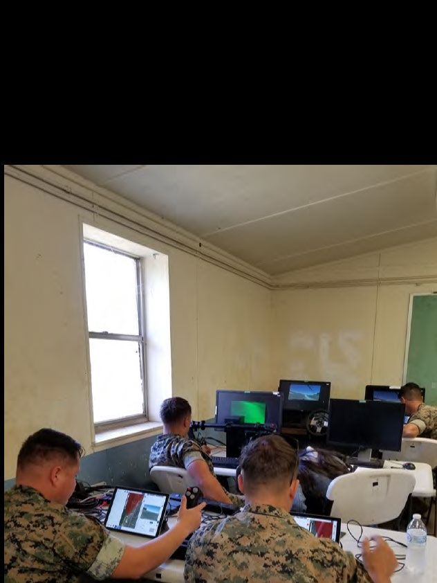
ARL-TR-8663 ● MAR 2019

US Army Wingman Joint Capability Technology
Demonstration (JCTD): Initial Soldier and Marine
Feedback on Manned–Unmanned Gunnery
Operations
by Kristin E Schaefer and Anthony L Baker
Human Research and Engineering Directorate, CCDC Army Research Laboratory

Ralph W Brewer
Vehicle Technology Directorate, CCDC Army Research Laboratory

E Ray Pursel and Brandon Gipson
Naval Surface Warfare Center Dahlgren Division

Steve Ratka
DCS Corp.

James Giacchi
CCDC Armaments Center

Eduardo Cerame and Kristin Pirozzo
CCDC Ground Vehicle Systems Center

Approved for public release; distribution is unlimited.

Form Approved
                                 REPORT DOCUMENTATION PAGE                                                                                                         OMB No. 0704-0188
Public reporting burden for this collection of information is estimated to average 1 hour per response, including the time for reviewing instructions, searching existing data sources, gathering and maintaining the
data needed, and completing and reviewing the collection information. Send comments regarding this burden estimate or any other aspect of this collection of information, including suggestions for reducing the
burden, to Department of Defense, Washington Headquarters Services, Directorate for Information Operations and Reports (0704-0188), 1215 Jefferson Davis Highway, Suite 1204, Arlington, VA 22202-4302.
Respondents should be aware that notwithstanding any other provision of law, no person shall be subject to any penalty for failing to comply with a collection of information if it does not display a currently
valid OMB control number.
PLEASE DO NOT RETURN YOUR FORM TO THE ABOVE ADDRESS.
1. REPORT DATE (DD-MM-YYYY)                             2. REPORT TYPE                                                                      3. DATES COVERED (From - To)
March 2019                                              Technical Report                                                                    October 2018–June 2019
4. TITLE AND SUBTITLE                                                                                                                       5a. CONTRACT NUMBER
US Army Wingman Joint Capability Technology Demonstration (JCTD): Initial
Soldier and Marine Feedback on Manned–Unmanned Gunnery Operations                                                                           5b. GRANT NUMBER

                                                                                                                                            5c. PROGRAM ELEMENT NUMBER

6. AUTHOR(S)                                                                                                                                5d. PROJECT NUMBER
Kristin E Schaefer, Ralph W Brewer, Anthony L Baker, E Ray Pursel, Brandon
Gipson, Steve Ratka, James Giacchi, Eduardo Cerame, and Kristin Pirozzo                                                                     5e. TASK NUMBER

                                                                                                                                            5f. WORK UNIT NUMBER

7. PERFORMING ORGANIZATION NAME(S) AND ADDRESS(ES)                                                                                          8. PERFORMING ORGANIZATION REPORT NUMBER
US Army Combat Capabilities Development Command
Army Research Laboratory                                                                                                                    ARL-TR-8663
ATTN: FCDD-RLH-FD
Aberdeen Proving Ground, MD 21005-5425
9. SPONSORING/MONITORING AGENCY NAME(S) AND ADDRESS(ES)                                                                                     10. SPONSOR/MONITOR'S ACRONYM(S)
Army Research Laboratory, APG, MD                                                                                                           ARL/GVSC
Ground Vehicle Systems Center, Warren, MI                                                                                                   11. SPONSOR/MONITOR'S REPORT NUMBER(S)

12. DISTRIBUTION/AVAILABILITY STATEMENT
Approved for public release; distribution is unlimited.

13. SUPPLEMENTARY NOTES

14. ABSTRACT
This report is part of the Wingman Joint Capabilities Technology Demonstration program. During the week of 22–26 October
2018, two crews (one Soldier crew and one Marine crew) participated in a joint manned–unmanned teaming exercise to
evaluate training and operation during gunnery operations on a live-fire range. This report provides the general feedback on
the Wingman program training, teaming, robotic technology, and design of the Warfighter Machine Interface display. Specific
advancements related to robotic vehicle technology, the displays, and training are reported.

15. SUBJECT TERMS
Wingman, robot, manned–unmanned teaming, next generation combat vehicle, lethality
                                                                                         17. LIMITATION               18. NUMBER            19a. NAME OF RESPONSIBLE PERSON
16. SECURITY CLASSIFICATION OF:                                                             OF                           OF
                                                                                                                                            Kristin E Schaefer-Lay
                                                                                            ABSTRACT                     PAGES
a. REPORT                  b. ABSTRACT                   c. THIS PAGE                                                                       19b. TELEPHONE NUMBER (Include area code)
                                                                                                  UU                         41
Unclassified                 Unclassified                   Unclassified                                                                    (410) 278-5972
                                                                                                                                                                                         Standard Form 298 (Rev. 8/98)
                                                                                                                                                                                        Prescribed by ANSI Std. Z39.18

                                                                                                         ii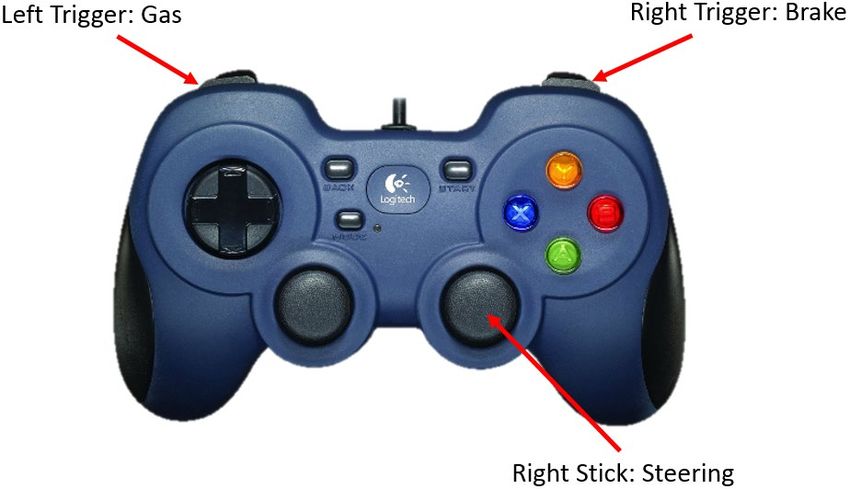
Contents

List of Figures                                              v

List of Tables                                               v

Summary                                                     vi

1.     Introduction                                          1
       1.1 Wingman Manned–Unmanned Teaming                   1
       1.2 Wingman Simulation Testbed                        4
       1.3 Soldier and Marine Event                          6
           1.3.1 Crews                                       6
           1.3.2 Schedule of Events                          7
           1.3.3 Training                                    7
           1.3.4 Dry-Fire Engagement Run                     9
           1.3.5 Blank-Fire Engagement Run                   9
           1.3.6 Stationary Live-Fire Engagement Runs       10

2.     Feedback                                             10
       2.1 Training Overview                                10
       2.2 Training Feedback                                11
           2.2.1 Areas for Improvement                      11
           2.2.2 Positive Feedback                          12
           2.2.3 WMI Display Questions                      13
           2.2.4 Controller Questions                       13
       2.3 MUM-T Operations Feedback                        14
           2.3.1 RVO Crewstation                            14
           2.3.2 RVG Crewstation                            14
           2.3.3 LRAS3 Operator Crewstation                 16
           2.3.4 VC Crewstation                             17
           2.3.5 Team Communication                         17
       2.4 Feedback Specific to the WMI Display Design      18
           2.4.1 General WMI Comments                       18

Approved for public release; distribution is unlimited.
                                                      iii
2.4.2      Camera Sensor Widget                    18
               2.4.3      Map Widget                              19
               2.4.4      BSO                                     19
       2.5 Feedback on General Operations                         20
           2.5.1 Situation Awareness and Battlefield Management   20
           2.5.2 Trust                                            21
           2.5.3 Interaction and Control                          23

3.     Conclusions                                                24

4.     References                                                 26

Appendix. Scoring Matrix                                          28

List of Symbols, Abbreviations, and Acronyms                      32

Distribution List                                                 33

Approved for public release; distribution is unlimited.
                                                      iv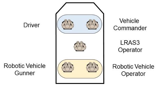
List of Figures
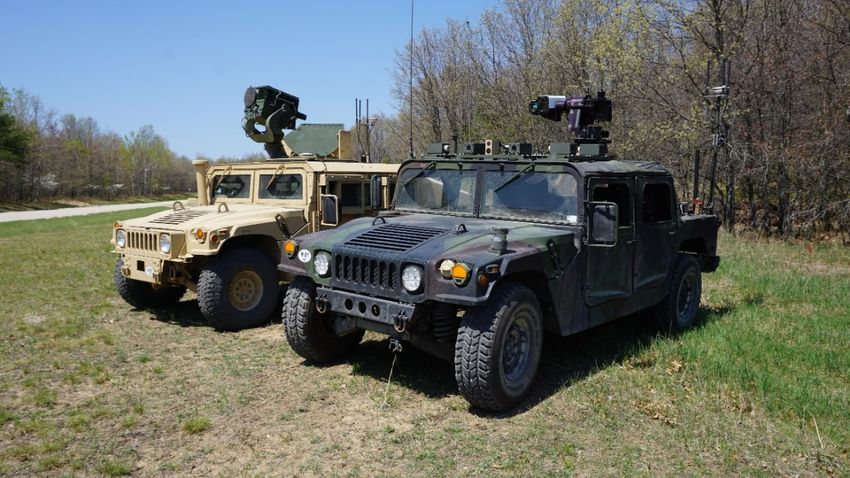
Fig. 1 Image of the real-world manned vehicle (left) and robotic weaponized
vehicle (right) ........................................................................................ 2
Fig. 2 Example of the three WMI displays for the commander (left), robotic
vehicle gunner (center), and robotic vehicle operator (right) ............... 3
Fig. 3 Simulation testbed at Fort Benning, Georgia (left); crewstation layout
in the C2 vehicle (right) ........................................................................ 4
Fig. 4 RVG control grip and button layouts. ................................................... 4
Fig. 5 Gamepad controller for the RVO crewstation ...................................... 5
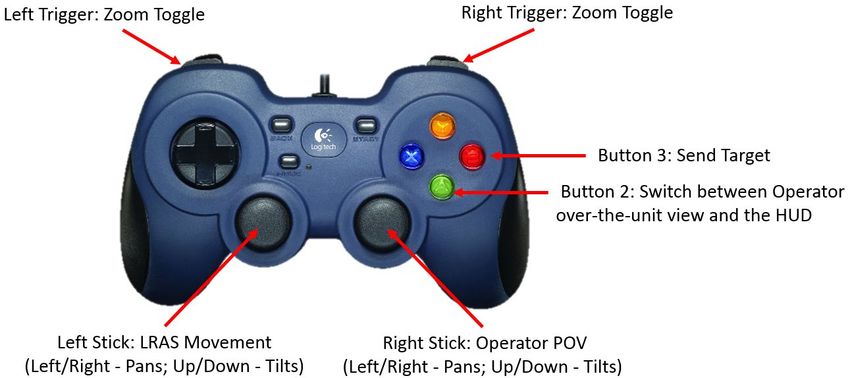
Fig. 6 Gamepad controller layout for LRAS3 operator crewstation ............... 5
Fig. 7 Outline of when to use a type of fire command .................................... 8
List of Tables
Table 1 Issues Warfighters encountered during dry, blank, and stationary live
fire runs ............................................................................................... 21
Table A-1 Table IV performance scores per run.................................................. 29
Table A-2 Performance scores for dry runs ......................................................... 30
Table A-3 Performance scores for blank runs ...................................................... 30
Table A-4 Performance scores for stationary live-fire runs ................................. 31
Approved for public release; distribution is unlimited.
vSummary
The larger scientific community is developing processes for accurate and
appropriate training and assessment of human–robot teams. One of the main
difficulties in identifying these methods is the lack of real-world robotic systems
that require the interoperability of the team to meet set performance metrics. During
the week of 22–26 October 2018, two five-man crews (one Marine crew and one
Soldier crew) performed real-world manned–unmanned teaming conducting live-
fire gunnery evaluation exercises for the Wingman Joint Capability Technology
Demonstration program.
The five-man crew was located onboard a Command and Control vehicle and
operated a separate weaponized unmanned Robotic Wingman vehicle. Both
vehicles were the High-Mobility Multipurpose Wheeled Vehicles. The Warfighter
teams first used the Robotic Wingman simulation testbed for training prior to
operating the real-world Robotic Wingman vehicles during multiple gunnery
operations on the Carmouche Range located at Ft Benning, Georgia. Operations
included observation of a full live-fire demonstration conducted by the engineering
team, and the Soldier and Marine teams engaged in dry-fire, blank-fire, and
stationary live-fire conditions.
Following the events, the Warfighters provided feedback related to training and
their experiences with the various aspects of the exercises. This report provides the
Warfighter feedback to support the development of appropriate training, technical
needs for the simulation testbed to support effective training, and interaction with
the real vehicles, controllers, and Warfighter Machine Interface displays.
Approved for public release; distribution is unlimited.
vi1. Introduction
The US Army seeks to identify current and emerging technologies and projections
of technology-enabled concepts that could provide significant military advantage
during operations in complex, contested, or congested environments between now
and 2028. These include advanced technologies that support integration of joint
manned–unmanned teaming (MUM-T) initiatives. As unmanned technologies
advance from traditional teleoperation to more interdependent operations with
advanced autonomous decision-making capabilities, it is essential to develop
appropriate collaboration between the human and autonomy-enabled team
members (Phillips et al. 2011). For effective teaming to occur, throughout the
development life cycle of the technology, it must include human team members to
advance the potential for trusted team development. A driving reason for this focus
on the human element in MUM-T operations is that effective teaming and
appropriate use of the technology depend on the human’s understanding of the
system, its behaviors, and the reasoning behind those behaviors (Chen et al. 2014).
If human expectations do not match system behaviors, people will question the
accuracy and effectiveness of the system’s action (Bitan and Meyer 2007; Seppelt
and Lee 2007; Stanton et al. 2007). Such skepticism can lead to degraded trust
which, in turn, can be directly linked to misuse or disuse of the system, even if it is
operating effectively (Lee and See 2004; Schaefer and Straub 2016).
1.1 Wingman Manned–Unmanned Teaming
The US Army Robotic Wingman program provides a real-world example for
understanding manned–unmanned teaming that occurs throughout system
development. The goal of the Wingman program is to provide advanced robotic
technologies as well as experimentation to assess and demonstrate increased
autonomous capabilities for joint manned and unmanned ground combat vehicles.
The team currently consists of a five-man crew on the Command and Control (C2)
vehicle (left side Fig. 1) comprising the manned vehicle driver, vehicle commander
(VC), long-range advanced scout surveillance system (LRAS3) operator, robotic
vehicle operator (RVO), and robotic vehicle gunner (RVG), paired with a single
unmanned weaponized robotic ground vehicle (right side Fig. 1).
Approved for public release; distribution is unlimited.
1Fig. 1 Image of the real-world manned vehicle (left) and robotic weaponized vehicle (right)
Mobility operations are being developed to support multiple levels of autonomy
including control-by-wire or teleoperation, waypoint finding, and semi-
autonomous driving via defined go/no-go zones, leading to advanced autonomy. In
line with most research discussions on levels of autonomy (e.g., Parasuraman et al.
2000), it is unlikely that the RVO will maintain only a single type of control
authority throughout a gunnery mission. Therefore, a goal for effective teaming is
to assess the capability of the operator to appropriately toggle between control
authority modes with respect to team or mission needs. What we aim to limit are
inappropriate changes in control authority, or misuse of the system, due to added
stress, workload, fatigue, or a degradation in trust. To reach this end, the operator
must have accurate and appropriate task, mission, and environmental information
from the other human team members as well as from the Wingman vehicle.
Unlike mobility operations, there has been very little research in unmanned gunnery
operations. Gunnery operations require interaction between members of the
manned crew and the robotic vehicle’s mobility and fire control system (FCS). The
autonomy-enabled features of the FCS include detecting potential targets within the
weapon’s field of view, tracking user-selected targets, and keeping the weapon
trained on those targets while applying a ballistic solution. The human team
members are still responsible for any user-applied adjustments and the global
decision-making associated with firing on a target. The VC ultimately authorizes
engagement of a target, and the RVG is in the loop for the actual trigger pull. Due
to the limitations in the current research, there is a specific need for research to
characterize the complexities in detecting, identifying, and engaging targets
Approved for public release; distribution is unlimited.
2revolving around sensor and networking delays and the limited operator situation
awareness (SA) inherent in unmanned weapon systems.
Team coordination and performance are closely related (Salas et al. 2009), and
effective communication results in improvements in other team processes and
outcomes (Mathieu et al. 2000; Kozlowski and Ilgen 2006). Efficient team
communication is critical for target engagement given the coordinated nature of
gunnery operations. Since Wingman adds multiple types of autonomy to the
equation, it is even more important to understand how team communication relates
to performance, given that human–agent interaction still lacks the fluidity of
human–human interaction (Bisk et al. 2016). As such, there is a need to test our
methods for analyzing team communication to ensure they are applicable to the
human–agent context.
Further, performance is a direct result of the MUM-T interoperability, where the
manned vehicle is often located at a remote position with respect to the Wingman
vehicle, which can be outside of direct line of sight. Therefore, in support of prior
research (see Chen et al. 2014; Schaefer et al. 2017c), a technical solution for
providing shared SA amongst the human team and with the robotic combat vehicle
(RCV) is key to effective teaming. Accomplishing this goal rests with the
development of the Warfighter Machine Interface (WMI), which provides
interactive customizable displays for the VC, RVG, and RVO (Fig. 2). Each
Wingman WMI has access to shared SA data, categorized by subsystem across the
bottom of each display, including major subsystems such as map, sensor, and alerts.
The map screen provides an interactive aerial image, MIL-STD-2525B symbols
(1999), mobility plans, sensor fields of view, and grid reference lines. The sensor
screen provides live video feeds with overlays providing SA such as azimuth,
elevation, heading, and field of view. The VC and RVG use the sensor feeds to
positively identify potential targets for engagement. Each WMI also has SA data
available in a common toolbar and prioritized alerts visible as pop-ups at the top of
the screen.
Fig. 2 Example of the three WMI displays for the commander (left), robotic vehicle gunner
(center), and robotic vehicle operator (right)
Approved for public release; distribution is unlimited.
31.2 Wingman Simulation Testbed
The Wingman simulation testbed uses a software-in-the-loop design whereby all
the same vehicle software is accessible in a tabletop configuration to support team
training prior to operation on the real-world vehicles. Specific technical details
outlining the development of this simulation testbed can be found in ARL-TN-0830
(Schaefer et al. 2017b), ARL-TR-8254 (Schaefer et al. 2017a), and ARL-TR-8572
(Schaefer et al. 2018). More information on how the simulation testbed supports
human–agent teaming can be found in Brewer et al. (2018). The current
instantiation of the simulation testbed supports all five crewstations (Fig. 3),
including the three WMI displays for the VC, RVG, and RVO, and the controllers
for the driver, RVG, RVO, and LRAS3 operator.
Fig. 3 Simulation testbed at Fort Benning, Georgia (left); crewstation layout in the C2
vehicle (right)
The design of the RVG crewstation supports the actual gunner handle, as well as a
gamepad and joystick for when the actual handle is not available (Fig. 4 for button
layouts).
Fig. 4 RVG control grip and button layouts.
The RVO crewstation supports a gamepad controller matching the use of the
gamepad controller in the actual vehicle (Fig. 5).
Approved for public release; distribution is unlimited.
4Fig. 5 Gamepad controller for the RVO crewstation
The C2 vehicle driver crewstation supports a Logitech gaming wheel and pedal
controller. The LRAS3 operator crewstation supports a gamepad and the LRAS3
handgrips designed by Night Vision labs. Button configurations and layouts for the
LRAS3 operation can be located in the PdM Ground Sensors MWO Self-Training
Guide for LRAS3 Operation (MCoE 1996). The gamepad controller button layout
is provided in Fig. 6.
Fig. 6 Gamepad controller layout for LRAS3 operator crewstation
For training purposes, the virtual environment used was the gunnery range from
Camp Grayling, Michigan. This terrain was generated using real-world terrain
Approved for public release; distribution is unlimited.
5elevations from the US Geological Survey and has been aligned between the
software of the two game engines. In addition to duplicating the terrain geometry,
targets from the Camp Grayling range are duplicated in position and behavior to
provide targets for detection and engaging. The full training program is described
in Section 2.3.3.
1.3 Soldier and Marine Event
The purpose of this data collection was to get Soldier and Marine feedback on the
training and team operation to conduct gunnery exercises with a manned–
unmanned team. These teams were the first Warfighter teams to ever operate the
Robotic Wingman platform. Outcomes from this study should inform future
training, features of the RCV, and development of the WMI to support future
MUM-T operations.
1.3.1 Crews
Two crews participated in this study: the Marines from the 1st Marine Logistics
Group Combat Skills Training School (CSTS) and the Soldiers from the 3rd
Squadron, 16th Cavalry Regiment. An engineering team member filled the role of
the C2 vehicle driver for both crews. The Warfighters filled the remaining four
crewstations.
The selection of the CSTS Marines for the Wingman Joint Capability Technology
Demonstration (JCTD) was based on their experience and expertise on machine
gun team operations, concept of employment, and employing tactics, techniques,
and procedures (TTPs). As infantry subject matter experts, the CSTS Marines train
Marines and Sailors in regiments, battalions, and companies across the Marine
Logistics Group. Their primary focus is on combat training courses. These courses
cover tactical leadership principles, machine gun functions, combat orders, and
procedures to counter threats and mitigate risks to Marine forces conducting tactical
convoys. Each of the four Marines who attended the JCTD has deployed in support
of Combat Operations during Operation Enduring Freedom/Operation Iraqi
Freedom.
The four Soldiers were selected from the 1st Squadron, 16th Cavalry Regiment,
316th Cavalry Brigade. These Soldiers hold the military occupational specialty of
19D, Cavalry Scout. They are proficient in reconnaissance, surveillance, and target
acquisition, and subject matter experts in movement and maneuver. In addition,
these Soldiers are a part of the 316th Cavalry Brigade, whose only mission is to run
the courses training Cavalry Enlisted Soldiers (19D, 19K One Station Unit
Training), Officer Courses (Armor Officer Basic Course), and Advanced
Approved for public release; distribution is unlimited.
6Reconnaissance Leader Training (Army Reconnaissance Course and Cavalry
Leader’s Course). As such, these Soldiers have a premiere pedigree to understand
the TTPs necessary to fight and win on today’s technologically advanced
battlefield, especially the ability to move, shoot, and communicate. All of the
Soldiers selected were also previously qualified on a Table IV, making them
familiar with the exact requirements of the Wingman event.
1.3.2 Schedule of Events
• Monday, 22 October 2018: Classroom training, simulation training, and one
dry-fire training exercise for each crew
• Tuesday, 23 October 2018: Observed engineering team’s live-fire
demonstration; Soldier and Marine crews each conducted one stationary
live-fire exercise
• Wednesday, 24 October 2018: Soldier and Marine crews each conducted
one blank-fire exercise and two dry-fire exercises
• Thursday, 25 October 2018: Soldier and Marine crews each conducted one
dry-fire exercise and one stationary live-fire exercise
1.3.3 Training
A combination of classroom, simulation, and live field instruction on the gunnery
ranges was used to facilitate crew training. Classroom training consisted of training
from the Training Circular (TC) 3-20.31, Training and Qualification, Crew (DOA1
2015) and TC 3-20.31-4, Direct Fire Engagement Process (DOA2 2015).
Simulation training was used to train the crew on respective crewstation roles,
controllers, and user interface displays, as well as how to work together to engage
targets using the Wingman system. Hands-on field instruction was used to practice
gunnery operations on a live range working as a team with a real robotic system
with direct support and direction from the engineering team.
For classroom training, understanding the crew engagement process is integral in
determining how to effectively conduct live-fire gunnery evaluations. The training
of the direct fire engagement process focused on the direct fire engagement
commands. The discussion centered on the standard structure of the engagement
process, the guidelines for executing conduct of fire, and the techniques that
facilitate rapid and lethal engagements. The engagement process known as DIDEA
is an acronym for Detect, Identify, Decide, Engage, and Assess.
The crew must rapidly acquire targets, identify them as potential threats, make a
decision to engage or not engage a target, engage the target(s), and then assess the
Approved for public release; distribution is unlimited.
7effects of each firing action. The crew initiates the direct fire engagement process
with a fire command. The crews were trained on the different types of commands,
the elements, and the terminology. These included an initial command at the
beginning of an engagement; a subsequent command to continue engaging the same
target; and supplemental commands to service a different target during the same
engagement. The flowchart in Fig. 7 outlines when to use certain commands.
While the crew must know how to effectively engage a target, they must also
understand the evaluation process. Crew evaluations for the manned–unmanned
team are currently using the remote weapon station (RWS) evaluation process
defined by TC 3-20.31-4 (DOA2 2015). The evaluation takes into account the
posture (offense or defense), type of threat, posture of the threat, and the range of
the threat. Evaluators will expose targets during a 50-s window in which the crew
will have the opportunity to engage and destroy the target(s). Scoring consists of
performance, timing, and team communication. Penalties are assessed for safety
violations as well as minor infractions for the crew in response to commands during
the engagement process.
Fig. 7 Outline of when to use a type of fire command
Approved for public release; distribution is unlimited.
8The simulation provided a benign environment in which each crew member was
given one-on-one hands-on training using the controllers and WMI display. This was
followed up with practicing offensive and defensive engagements on a virtual
gunnery range from Camp Grayling, Michigan. Both manuals and guided practice
from the engineering and development team were used to train controller
functionality (i.e., button location and use) to lase targets (LRAS3 operator), control
teleoperation of the RCV (RVO), and engage targets (RVG). Similarly, individualize
instruction was provided to train the features, capabilities, and tasks required to
operate the RCV and communicate between the crew using the WMI displays for the
VC, RVO, and RVG. Manuals were provided as reference materials for each WMI
station. Crews training with the simulation provided an initial opportunity to practice
the concepts on team engagements learned during the classroom portion of the
training during multiple simulated offensive and defensive engagements.
Live field training included three main events. First, each crew member was given
an individualized review with the engineering team on their role, responsibilities,
controllers, and WMI capabilities. Second, the LRAS3 operator and VC were given
the opportunity to go on the range with the C2 driver with an engineering team
member on board the vehicle and the gunnery evaluator on the radio. This training
provided the opportunity for these team members to develop appropriate
communication between the C2 vehicle crewstations outside of the direct DIDEA
process. Training included identifying critical environmental features needed to
improve team communication for mobility (e.g., location of battle positions) for the
VC, and identifying and practicing lasing real targets by the LRAS3 operator. The
third training event was a full vehicle crew walkthrough of all of the daytime
engagements. The engineering team and evaluator were on the radio to provide
step-by-step directions for running through a full engagement exercise and
provided training on how to address technical questions and errors.
1.3.4 Dry-Fire Engagement Run
In a crawl–walk–run approach, the crews began by conducting evaluation exercises
on the course without using any ammunition. The crews would go through motions
of engaging the targets using the DIDEA process and dry firing the gun. This was
important to synchronize their crew duties prior to adding ammunition to the
process.
1.3.5 Blank-Fire Engagement Run
The blank-fire engagement runs were exactly the same as the dry-fire ones, except
with the introduction of blank ammunition. When the gunner pulled the trigger, the
gun would fire the blanks and retort, giving the gunner a more realistic view of
Approved for public release; distribution is unlimited.
9what is seen using live ammunition. The timing of completing the engagement
relied entirely on the sensing of the target by the VC (as was the case with the dry-
fire engagement runs).
1.3.6 Stationary Live-Fire Engagement Runs
Once the Soldiers and Marines were sufficiently trained and evaluated with dry and
blank fire, they were allowed to take part in the stationary live-fire engagement run.
The stationary live-fire engagements were similar to the dry- and blank-fire
engagement runs with two differences. First, the crews used live ammunition.
Second, to comply with an Army Test and Evaluation Command safety memo
restricting live fire while moving, the RCV was chocked to prevent vehicle
movement while the weapon was loaded. Defensive engagements did not change,
but offensive engagements were changed to reflect traffic control points. A traffic
control point engagement treats the evaluation as an offensive one with regard to
timing, but the vehicle does not move.
2. Feedback
Warfighters were given multiple opportunities to provide feedback throughout the
week. This included individual written feedback and group discussion on the
training, and daily group after-action reviews with directed questions. The
following subsections describe the training-specific feedback, MUM-T operations
feedback, and WMI recommendations and requests for future display options.
2.1 Training Overview
Overall, both teams felt that the classroom, simulation, and hands-on training with
the vehicles provided different but important capabilities. The classroom training
provided general instruction for the tasks, ranges, and team interactions. The
simulation training provided initial orientation to the WMI displays and controllers,
and an opportunity to practice team communication. Hands-on directed training
with the actual vehicles on the range provided a more in-depth orientation to the
team operations and the ability to practice what was learned during other training
sessions.
It was clear to both teams that the simulation did not directly match the real vehicle.
There were three major differences:
1) The RVG crewstation handle from the vehicle was not available for use
during training. Therefore, the RVG had initial practice with a gamepad
Approved for public release; distribution is unlimited.
10controller that had different button presses and different sensitivity than the
actual controller.
2) The simulation handle for the LRAS3 station was not as sensitive as the real
system. The LRAS3 operator had to continue to hold the simulation handles
in place to maintain directionality (otherwise it would auto-return to center).
The real system would stay in place.
3) The simulation testbed had the Autonomous Remote Engagement System
(ARES), which added autonomy features that supported gunnery operations
(i.e., autonomous slew-to-cue features) that were not activated on the real
vehicle. Both teams found this technology to be incredibly helpful and
wanted to use it on the actual vehicle.
In order to match the real-world system, engineers updated the software on the
simulation testbed prior to the first day of training. The update to the Robotic
Technology Kernel (RTK) and the Autonomous Navigation Virtual Environment
Laboratory were updated on 1 October 2018. ARES was updated to version
18.4-dev on 17 October 2018. The Unity server and clients were updated to version
4.2 and the WMI software updates on 19 October 2018. As a result, there were
some integration issues that occurred in simulation during training. As an example,
the incorrectly configured RVG WMI was having issues communicating with
ARES. This resulted in an initial inability of the RVG to select targets or slew to an
LRAS3 cue.
2.2 Training Feedback
The following subsections outline the written feedback from each participant
specific to the training program. Each subsection includes a response to how this
feedback could be addressed in either the training program or the technical
development of the Wingman system.
2.2.1 Areas for Improvement
1) Three out of eight participants felt the training was adequate and had no
direct feedback on how to improve training.
2) Two participants requested more hands-on training and practice with the
real-world vehicles. This was in part due to the previously listed deviations
between the simulation and the real system.
3) There was one request for a more in-depth orientation on the weapon system
and vehicle configuration.
Approved for public release; distribution is unlimited.
114) Two participants requested more “free form” or flexible training across
multiple test courses, with multiple target options. Overtraining a single
scenario can overbuild confidence.
5) There should be opportunities to practice potential events and errors that
could occur on the range. For example, what to do when the robotic vehicle
loses communication with the C2 vehicle, or how to address issues that the
robotic gunner noticed, such as the camera would jump when he would arm
the system.
The following procedures, training specifications, and technical developments
describe current work being done to address this feedback:
1) To account for variations between simulation and the real system,
procedures have been requested to have an earlier system development stop
time to allow for the simulation development team to have time for
integration and testing prior to training.
2) Additional classroom training, including videos and manuals, is being
developed to provide a more in-depth orientation on the weapon system and
vehicle configuration.
3) The simulation development team is currently integrating virtual
environments for the Ft Benning Multipurpose Range Center gunnery
ranges for scripted Table VI exercises, as well as more unscripted virtual
environments so Warfighters can get a more realistic feel for the future
capabilities, such as supporting a complex breach scenario.
4) Training is being revised to provide better instruction on handling different
types of events and errors. The best medium for training depends on the
type of errors. The Wingman team is currently looking at identifying the
best training protocols to account for this task.
2.2.2 Positive Feedback
Overall, all participants felt the training was successful. Use of classroom,
simulation, and range time together, with a focus on hands-on learning rather than
lecture, promoted effective team training rather than individual understanding
alone. Having a subject matter expert on hand to answer questions at the time of an
issue (rather than just at after-action review) improved retention on how to use the
controllers, displays, and the system more appropriately. There was a request for
more dry runs on the real system and a recommendation to keep the crews together
through all the training, even when something was role specific; this helps the team
understand the requirements of the other team members.
Approved for public release; distribution is unlimited.
12Participant feedback supports the importance of having classroom, simulation, and
live training, as each provides a different type of learning experience. Additional
multimedia resources are currently in development to support team operations and
role orientations. All future training will keep the crew together, whenever possible,
for all aspects of training.
2.2.3 WMI Display Questions
All participants felt confident using the WMI displays for interaction with the
Wingman RCV following training. There were no direction questions or requests
for clarification. Two questions were posed. First, after using the slew-to-cue
autonomy features in the simulation, participants requested use of this feature on
the real vehicles. They felt that it would greatly improve performance. The second
question was a technical question requesting a way to interface between the LRAS3
and the RVG cameras. The feeling behind this was with that type of extra
technology, the LRAS3 operator could support added shared SA when identifying
and tracking multiple targets.
In response to the participants’ questions, slew-to-cue is an option from the RVG
crewstation. However, due to technical issues with the elevation at this event, it was
not providing accurate referencing and therefore is not recommended for use on the
real system. To assist with shared SA for targeting purposes, the VC has the
capability to both the RVG and LRAS3 video feeds. For safety purposes, only the
gunner is able to slew the weapon system.
2.2.4 Controller Questions
Following training, there were no questions about the different controller features
or buttons. There was, however, a request for future technology to improve
classification of friendly versus hostile targets. Since this classification process
took a great deal of time for the VC to edit on the WMI, it was requested to find a
way for the LRAS3 operator to lase targets as friendly, hostile, or other.
The LRAS does not assign a designator to the target that it lases; the VC can use
the WMI to assign the level of threat, as well as specific features about the target,
using MIL-STD-2525. The current design of the WMI is designed so that users of
the WMI can change its features manually.
This feedback has the potential to influence how the Wingman WMI is designed.
Having users interact with the interface gives the developers much needed feedback
on how the user interface will be utilized and its overall usability. If from feedback
it becomes obvious users are missing how to use part of the interface, that portion
will be reevaluated. This allows the team to decide if it is graphical or a training
Approved for public release; distribution is unlimited.
13problem. Additionally, if many users request similar features, it could indicate to
the designers that the current implementation might need to be updated with said
feature.
2.3 MUM-T Operations Feedback
Notes written by the experimental team and audio recordings of the after-action
reviews were reviewed and compiled into the following feedback areas. The
feedback is separated as crewstation-specific and team communication.
2.3.1 RVO Crewstation
Two major comments specific to waypoint following were provided regarding the
RVO crewstation. First, one operator reported that on the first day, he had trouble
starting a waypoint plan and dropping points, stating that the process was not
intuitive. While this process was demonstrated during one-on-one training with
simulation and practiced with team operations, this comment suggests that more
training is needed prior to operation in the field. Additional training material is also
being developed to provide “how to” manuals and audio-visual training tools.
The second comment was that waypoint placement is offset and not consistent
when operating the real system. This is a technical issue with the real system. To
correct this issue, the map widget on the WMI will need to incorporate more
accurate vehicle localization. It was also noted that there was some difficulty in
creating and editing waypoint paths in a moving C2 vehicle. Additional testing was
done on-site with a stylus but was found to be more difficult than using a finger on
the touch display.
A request was made to be able to program multiple routes (e.g., primary, secondary,
tertiary) and switch between these routes. The current design of the WMI allows a
person to create and save plans that can later be recalled from a file. However,
having this additional on-screen visibility or transfer of paths could advance the
Wingman future capabilities. The WMI development team is currently looking into
the technical capabilities to support this type of feature function.
2.3.2 RVG Crewstation
Multiple comments were specific to controlling the weapon system, accessing
camera sensors, and accessing autonomous support for weapon system control:
1) The location of the arming switch on the handle required two-hand
operation or removal of the hand from the joystick. It is standard practice to
Approved for public release; distribution is unlimited.
14disarm the weapon system between engagements and firing positions. This
increased time and frustration with the controller.
2) Every time the palm was clicked while ARES was running, the gunner
camera jumps. The sudden shift in position can disorient the user and
requires the gunner to manually return to the position prior to the jump. In
addition, the gun sometimes jerks upward when removing the safety.
The operators’ standard procedure of disarming the RWS after every engagement,
including between targets in a single engagement, was not a concept of operation
considered by the development team. Disarming the Picatinny Lightweight Remote
Weapon System (PLWRWS) and then depressing the palm switch (as one would
to move the mount while disarmed) causes the PLWRWS to enter “surveillance
mode”, which super-elevates the weapon while maintaining the current cameral
elevation. This is the designed behavior. A result is that switching between armed
and disarmed, then, will cause the weapon and the camera to move, which will also
cause the operator’s video to jitter. Surveillance mode was disabled in the vehicle’s
remote weapons station firmware; the simulation training system will be updated
to match.
3) The RVG requested the option to switch between thermal and other camera
sensors.
The gunner’s station has the ability to pull up all of the sensor feeds. However, the
RVG was instructed to only pull up the LRAS and the weapons system because the
other feeds could cause encoder conflicts on the real vehicle. This can be rectified
with a video server, but our video server is currently under development. In
addition, there was not a day camera available on the PLWRWS sight package.
4) There is sensitivity in the handle making it difficult to manually adjust
targeting. When on target, the gunner wants to lock to target and for it to
stay. Further, after using ARES in simulation, the RVG wanted the
autonomous slew-to-cue for real engagements.
The sensitivity and responsiveness of the handle to move the RWS while
teleoperating is inherently a manual process (continuously adjusting the sensitivity
as range changes) and is an ongoing effect. The “correct” settings seem to be tied
directly to the operator’s workflow. If the operator relies heavily on selecting
targets on the WMI and letting ARES move the mount to and then track the target,
this is less of an issue than when an operator is more reliant on his own ability to
manipulate the weapon through teleoperation. Both styles should be possible, and
determining how to best enable or balance them requires further study.
Approved for public release; distribution is unlimited.
155) Some additional recommendations were made for specific WMI features to
support gunner operations. These included the capability to create a path for
the gun to rake while shooting; shot targets to be removed from the gunner
map; a notification when the weapon encounters (or clears) a malfunction;
and the addition of a second camera with a wide point of view to allow for
scanning the environment when not engaging targets.
Current discussions are underway with JCTD partners to determine which of these
features are possible to integrate and what could be included in the current
development plan. For example, to increase the capability to increase SA, the WMI
can support an eight-camera 360° SA sensor system (demonstrated in other
programs). However, these sensors are not currently part of the Wingman platform.
Additional updates to the menu books now include documentation on how to
reference both the weapon and gimbal status to determine potential weapon issues.
2.3.3 LRAS3 Operator Crewstation
Following training, the LRAS3 operators identified some concerns with the
controls in the simulation testbed. They noted that the LRAS handle was too jumpy
or jittery at times, which made focusing on precise targets difficult. In addition, the
simulation controller snaps back to a zero position when there is no force applied
to it. This does not match the actual system, which stays in the orientation where it
was left. It was also identified that the laser range finder was oversensitive and
would send multiple battle space object (BSO) symbols to the WMI displays for a
single identified target. This behavior only happened on the controller and not on
the gamepad. Finally, the operators made a suggestion for the simulation to allow
switching to a night mode in order to match the functionality on the actual LRAS3.
They also recommended that it would be beneficial for team performance to allow
the LRAS3 operator the capability to designate a target as friendly or hostile—the
current process for this designation takes the VC multiple menus and button presses
on the WMI display.
Based on this feedback, it was determined that the LRAS3 handle for simulation
was not a suitable interface for training with its current capabilities. The physical
constraints of its joystick-like movement mechanism included a physical spring that
returns the mechanism to center, causing the resolution of the movement encoder
to be insufficient for fine movement at high zoom levels. This was distracting
enough to the operators to be considered a detractor from training. In addition, there
is currently only one of these controllers and plans for several training systems.
Therefore, the simulation development team is looking into alternative options to
the LRAS3 handle.
Approved for public release; distribution is unlimited.
16To address the remaining comments, planned future LRAS3 operator station
development includes implementing the night camera and display. Implementation
of the LRAS3 menu system could enable additional functionality including the
ability for the operator to label a target as friendly or hostile.
2.3.4 VC Crewstation
The major comment regarding the VC crewstation was specific to the threats list.
Currently, the list of targets gets reordered during an engagement. The VC
requested an option to maintain a consistent order despite the arrival of new targets.
In response to this comment, there are current features within the WMI to support
this request. There are multiple ways to sort the threats list. In addition, new or
incoming targets can be added to the beginning or end of the list. Additional testing
will be conducted to identify alternative sorting methods, and the processes will be
included in future iterations of training.
2.3.5 Team Communication
There were three major comments about team communication. First, there was a
recommendation for more training on team communication between the crew
members. It was noted that “most firefights are over in 10s” and that
communication is the key to speeding up operations. Second, more information is
needed in relation to communication with the RCV. General instruction on the
physical parameters should be included in training (e.g., is line of sight necessary?).
It was also requested to have some way to visualize the effective communication
range between the C2 vehicle and the RCV on the WMI display. Third, more
effective error messages are needed when communication breaks down. Currently,
no instructions are provided on how to reestablish comms. Only an error message
is displayed stating that comms went down.
In response to these comments, additional training will be provided to practice crew
communication, identify RCV capabilities for communication (i.e., approximately
1 km) and communication ranges, and identify and recover from errors. Within the
WMI, the error message will be revised to define crew response. For example, when
communication is interrupted, a message will state that the crew needs to wait until
the system reestablishes communication. In addition, the RTK currently has support
to identify lost communication policies that are not currently being used in
Wingman. Additional testing will be conducted to see if there are any alternative
methods for reestablishing communication.
Approved for public release; distribution is unlimited.
172.4 Feedback Specific to the WMI Display Design
Feedback on all the WMI displays has been divided into general feedback and
widget-specific feedback (camera sensor, map, and BSO).
2.4.1 General WMI Comments
1) Users appreciated the height and position of screens on the real vehicle. It
allowed for visibility over the screen and through the windshield when
necessary.
2) It was not obvious how to adjust window sizes within the WMI.
Training manuals are being updated with a reference guide on widget placement,
and training during the classroom and simulation session will be revised to include
specific guidance. The capability to move widgets on the WMI allows for
individual preferences. Therefore, users will need some time to practice with the
display to identify an ideal configuration. From a technical goal, the WMI
development team is working on a way to save this layout customization.
3) When working with the real system, the VC noted difficulty with the screen
registering touches in cold weather (approximately 55° F).
Additional testing is needed for cold weather testing to stress the WMI and identify
its limitations.
4) Users identified a time that the command vehicle icon did not move on the
WMI.
The WMI is designed so that all assets move on the map widget. The only time an
asset would not move on the map widget is if the RTK software was not
functioning, there were lost comms, or there was a localization problem.
2.4.2 Camera Sensor Widget
1) Sensor screens are too small.
There is currently an aspect ratio that calculates the sensor screen size. However,
alternative options for customization are being explored by the development team
to account for “wasted space” on the video screens.
2) Commander requested controls to adjust view clarity of the sensor screens
similar to that of existing thermal optics that have controls to allow
adjustment of contrast and some other features.
Approved for public release; distribution is unlimited.
18The WMI currently has support to control the gain, brightness, and contract of a
sensor; however, only the main operator (not the viewers) has this capability.
Additional training will be included to demonstrate to users how to control these
features.
2.4.3 Map Widget
1) Users wanted the ability to “pinch and zoom” instead of being constrained
to using the slider to zoom in or out on the map or the real vehicle.
There are currently different options for this type of feature within the WMI. The
WMI development team will test these features with the current displays to
determine the best functional design.
2) Users requested contour lines on the map to aid in judgments of elevation.
This feature is not currently supported in the WMI, but it is a possible future feature.
3) Users requested a visible scale on the map to aid in judgment of distances.
The current version of the WMI supports this feature, but it was not operational
during this event. This feature will be tested and included in training.
4) The range fans for the vehicle, gunner, and LRAS3 need to be accurate for
better coordination between the crewstations. In addition, the range length
should match the capabilities of the sensor (not extend indefinitely). Users
also requested a toggle switch to turn on or off the range fans. Sometimes
they obstructed the view on the map.
The WMI development team is testing these features. There was a bug in the
version that was used during this event that caused the range fan to be too large and
too dark in color. A toggle option is being developed.
2.4.4 BSO
1) Users requested the option to customize phase lines with different colors
and names.
The current design of the WMI allows for customization of phase line names and
thicknesses. The variation in coloration is a feature that is currently in development.
Training during the simulation phase will include customizations on BSOs,
including phase lines.
2) Identifying a neutral BSO as either a friendly or hostile target and adding
additional features require a few different menus and multiple button
Approved for public release; distribution is unlimited.
19presses. It was recommended by the users that they be able to edit a BSO
by selecting the object.
It is possible to include a “long hold” type option to pull up the requested menu
features.
3) Vehicle fuel level would be highly practical for the VC to know.
This is a feature that is currently not instrumented on the Wingman vehicle.
2.5 Feedback on General Operations
This section outlines more general feedback regarding interactions with the
Wingman systems and interfaces.
2.5.1 Situation Awareness and Battlefield Management
When asked, Soldiers and Marines reported no instances of information overload.
To the contrary, they requested more information to help improve team and shared
SA.
1) Users noted that there were no issues with voice communication between
crew members.
2) It was requested to add in a small WMI display for the LRAS3 operator (if
possible) to help maintain shared SA with the team. This would reduce the
number of times the operator would need to reenter the C2 vehicle for
additional direction or clarification.
3) Users suggested the inclusion of default layouts (or let users save layouts)
for the WMI. This type of feature would allow users to return to these
default layouts with a click of a button on the display. This helps prevent
users from becoming overwhelmed when the display becomes too cluttered
with docked and pop-up windows
4) Some specific features noted to improve SA include the change in color
when the ammunition round count was low, and the capability to see
multiple crew sensor screens concurrently (e.g., LRAS and gunner). These
features supported team operations during target engagements.
5) VCs noted that the current C2 vehicle cannot effectively support dismounts.
This restricts operational flexibility.
6) In a commonly recurring theme, there was a request for redundant systems,
which would allow the crew to still drive and fire the robotic vehicle in the
event of system failures.
Approved for public release; distribution is unlimited.
202.5.2 Trust
Trust is a critical consideration when humans interact with automated systems.
Ineffective systems can damage operator trust of their equipment and lead to later
issues where systems are not used correctly, so it is important to understand how
the Wingman crews perceive the effectiveness and safety of the robotic system. The
following main trust issues were identified:
1) Multiple comments from crew members indicated that losing connectivity
to the robotic vehicle damaged their trust of the system.
2) The RVO often felt underloaded and could have been assigned more tasks.
3) Users reported feeling unsafe with the weapon system due to reliability issues.
The full list of issues including team coordination, usability, and technical errors
identified from recordings of crew operations is provided in Table 1.
Table 1 Issues Warfighters encountered during dry, blank, and stationary live fire runs
Date Run Crew Type of issue Actual issue Engagement
22 Oct Dry Marine Team Discussing commands for target Before 1
coordination engagement
Usability Coordinate lasing and range finding Before 2
with LRAS and RWS
Technical RCV not working, lost comms with During 3
error RVO
Technical RWS jumped when switching to During 4 & 7
error “fire” (two times)
22 Oct Dry Army Team Discussing incorrect lasing distance Before 3
coordination
Technical RWS jumped when switching to During 4
error “fire”
Technical RVG lase not working correctly During 5
error
23 Oct Live Army Technical RWS misfire (two times) During 3 & 4a
error
Technical Incorrect lasing and range acquisition After 4a
error
Technical Issue regaining control of RWS after Before 4b
error e-stop
Technical RVO WMI station issues: Before 6
error intermittently went blank, freezing,
some problems with RCV movement
Note: Each run had a maximum of seven engagement trials. Some of the engagement trials were attempted more
than once due to an issue that may have occurred.
a First attempt of an engagement trial
b Second attempt of an engagement trial
Approved for public release; distribution is unlimited.
21Table 1 Issues Warfighters encountered during dry, blank, and stationary live fire runs
(continued)
Date Run Crew Type of issue Actual issue Engagement
23 Oct Live Marine Technical RVG did not have control of the Before 3
error weapon
Technical RWS misfire During 3a
error
Team Discussing incorrect lasing distance After 3a
coordination
Technical Incorrect lasing and range acquisition During 6a & 7
error (two times)
24 Oct Blank Marine Technical RWS misfire (two times) During 1 & 3
error
Usability Team requested to remove GoPro After 1
cameras from windshield due to
obstructing visibility
Technical VC WMI was “super pixellated” During 3
error
24 Oct Blank Army No issues No issues noted No issues
noted noted
24 Oct Dry Marine Team VC instructed RVO to move the During 5a
coordination RCV in a way that did not let RVG
point the weapon far enough left; this
led to team retrying the engagement
24 Oct Dry Army Technical RVG video sensor issues: During 3 & 4
error intermittent freezing and “choppy”
feed
24 Oct Dry Marine Technical Lost comms: RVO lost connection to Bounding to 3
error RCV, and lost ability to teleop RCV;
IMU failed
24 Oct Dry Army Technical RCV was moving unusually slow Bounding to 3
error during bound
Training VC needed more training on accurate During 3
slewing of the RWS
25 Oct Live Army Technical RWS jumped up on RVG's screen During 1 & 2
error while “mid-trigger pull” (three times)
Technical RWS fired at incorrectly high angle During 2
error leading to engagement ceasefire
25 Oct Dry Marine Technical RVG feed completely blurry when During 3
error zoomed all the way in
Note: Each run had a maximum of seven engagement trials. Some of the engagement trials were attempted more
than once due to an issue that may have occurred.
a First attempt of an engagement trial
b Second attempt of an engagement trial
Approved for public release; distribution is unlimited.
22You can also read