Evaluation of existing technologies designed for helicopter against wire-strike
←
→
Page content transcription
If your browser does not render page correctly, please read the page content below
Iowa State University Capstones, Theses and
Graduate Theses and Dissertations                                                            Dissertations

2021

Evaluation of existing technologies designed for helicopter
against wire-strike
Lionel Mizero
Iowa State University

Follow this and additional works at: https://lib.dr.iastate.edu/etd

Recommended Citation
Mizero, Lionel, "Evaluation of existing technologies designed for helicopter against wire-strike" (2021).
Graduate Theses and Dissertations. 18563.
https://lib.dr.iastate.edu/etd/18563

This Thesis is brought to you for free and open access by the Iowa State University Capstones, Theses and
Dissertations at Iowa State University Digital Repository. It has been accepted for inclusion in Graduate Theses and
Dissertations by an authorized administrator of Iowa State University Digital Repository. For more information,
please contact digirep@iastate.edu.

Evaluation of existing technologies designed for helicopter against wire-strike

                                                 by

                                           Lionel Mizero

                             A thesis submitted to the graduate faculty

                    in partial fulfillment of the requirements for the degree of

                                      MASTER OF SCIENCE

                        Major: Civil Engineering (Structural Engineering)

                                 Program of Study Committee:
                             David J. Eisenmann, Co-major Professor
                              Simon Laflamme, Co-major Professor
                                          Jiehua J. Shen

 The student author, whose presentation of the scholarship herein was approved by the program
of study committee, is solely responsible for the content of this thesis. The Graduate College will
ensure this thesis is globally accessible and will not permit alterations after a degree is conferred.

                                       Iowa State University

                                            Ames, Iowa

                                                2021

                      Copyright © Lionel Mizero, 2021. All rights reserved.
ii
TABLE OF CONTENTS
Page
LIST OF FIGURES ....................................................................................................................... iv
LIST OF TABLES ......................................................................................................................... vi
NOMENCLATURE ..................................................................................................................... vii
ACKNOWLEDGMENTS ........................................................................................................... viii
ABSTRACT ................................................................................................................................... ix
CHAPTER 1. INTRODUCTION ....................................................................................................1
Problem Statement ..................................................................................................................... 1
Research Objectives .................................................................................................................. 2
Research Significance................................................................................................................ 2
Data Sources and Methodology ................................................................................................. 3
Organization of the Thesis ......................................................................................................... 3
CHAPTER 2. WIRE-STRIKE ACCIDENTS DATA ANALYSIS ................................................4
Overview of Wire-Strike Accident ............................................................................................ 4
Wire-Strike Accidents by Operation Category .................................................................... 6
Helicopter Model Involved in Wire-Strike .......................................................................... 8
Helicopters Equipped with Onboard Devices .................................................................... 11
Number of Pilots Involved in Wire-Strike Accidents between 2005 and 2018 ................. 12
Fatal Accidents Investigation ............................................................................................. 14
Profile of Pilots Engaged in Fatal Wire-Strike................................................................... 17
Probable Causes of Wire-Strike Accidents ........................................................................ 19
Types of Wires of Concern ...................................................................................................... 19
Summary of Wire-Strike Accidents ........................................................................................ 21
Nature of Helicopter Flights .................................................................................................... 22
Rotorcraft Pilots Need to Fly Safely........................................................................................ 23
CHAPTER 3. WIRE-STRIKE EXISTING TECHNOLOGIES ....................................................24
Powerline Detection System (PDS) ......................................................................................... 24
Obstacle Warning System (OWS) ........................................................................................... 28
Helicopter Laser Radar (HELLAS) .................................................................................... 28
Laser Obstacle Avoidance Marconi (LOAM) .................................................................... 31
Helicopter Terrain Awareness and Warning System (HTAWS) ............................................. 33
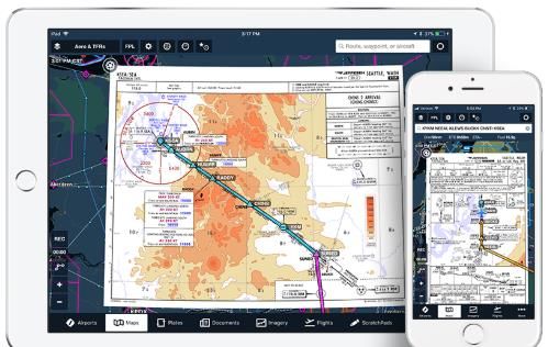
Sandel's ST3400H HeliTAWS ........................................................................................... 34
Obstruction Collision Avoidance System (OCAS) ................................................................. 36
Obstacle Collisions Avoidance System AS........................................................................ 36
Terma Obstruction Light Control (OLC) ........................................................................... 39
Aerial Wire Markers ................................................................................................................ 41
Wire Strike Protection System (WSPS) .................................................................................. 43
iii

    Electronic Flight Bag (EFB) .................................................................................................... 45
       Foreflight Mobile Application............................................................................................ 45
    Summary of Technologies ....................................................................................................... 47

CHAPTER 4. SUMMARY OF FINDINGS AND RECOMMENDATIONS .............................51
  Summary of Findings .............................................................................................................. 51
  Recommendation ..................................................................................................................... 52
    Future Work for Phase II: Sensor Package Design ............................................................ 53

CHAPTER 5. CONCLUSION.......................................................................................................55

REFERENCES ..............................................................................................................................57
iv

                                                  LIST OF FIGURES

                                                                                                                           Page

Figure 1. Number of wire-strike accidents per year from 2005 to 2018......................................... 4

Figure 2. Comparison of wire-strike accidents between two decades ............................................ 6

Figure 3. Number of accidents by operation type ........................................................................... 7

Figure 4. Accidents occurred in general aviation and agricultural operations ............................... 8

Figure 5. Accident distribution per operation category .................................................................. 8

Figure 6. Distribution of wire-strike by aircraft type ................................................................... 11

Figure 7. The age ranges for pilots involved in all strike cases .................................................... 13

Figure 8. Flying experience of pilot involved in all strike events ................................................ 13

Figure 9. Fatal accident by operation type .................................................................................... 14

Figure 10. Distribution of fatal accident by operation type .......................................................... 15

Figure 11. Distribution of wire-strike by aircraft type involved in fatal accidents....................... 16

Figure 12. Ages ranges of pilots engaged in fatal accidents ......................................................... 18

Figure 13. Flight experience of pilots involved in fatal accidents ................................................ 18

Figure 14. Phases of flight by strike category............................................................................... 19

Figure 15. Powerline, Highway 35, and Cambridge ..................................................................... 20

Figure 16. Communication tower guy-wires, I-35 West .............................................................. 20

Figure 17. Distribution of strike by wire type............................................................................... 21

Figure 18. Powerline Detection System main unit (Craig, 2016a) ............................................... 25

Figure 19. The HELLAS SHU (Münsterer et al., 2014) ............................................................... 29

Figure 20. LOAM Sensor Head Unit (Sabatini et al., 2014) ........................................................ 31

Figure 21. ST34000H HeliTAWS® (Avionics, S., 2016). ........................................................... 34

Figure 22. OCAS AS (Vangen, 2011) .......................................................................................... 37
v

Figure 23. Terma OLC radar SCANTER 5202 (Patterson Jr & Canter, 2018) ............................ 39

Figure 24. Ball marker (FAA Wag Aero, 2020) ........................................................................... 41

Figure 25. ForeFlight EFB (Liya, 2017) ....................................................................................... 46
vi

                                                   LIST OF TABLES

                                                                                                                          Page

Table 1. Number of wire-strike accidents that occurred between 2005 and 2018 .......................... 5

Table 2. Rotorcraft type involving in wire-strike accidents ........................................................... 9

Table 3. Aircraft type involved in wire-strike equipped with safety devices aboard ................... 12

Table 4: Helicopter model resulted in fatal accident .................................................................... 15

Table 5. Aircraft type with onboard devices that resulted in fatal accidents ................................ 17

Table 6. Comparison of current technologies ............................................................................... 48

Table 7. Basic specifications of the systems ................................................................................. 49
vii

                NOMENCLATURE

FAA                  Federal Aviation Administration

NTSB                 National Transportation Safety Board

ATSB                 Australian Transport Safety Bureau

TSB of Canada        Transportation Safety Board of Canada

VFR                  Visual Flight Rules

GPS                  Global Positioning System

HTAWS                Helicopter Terrain Awareness & Warning System

LOAM                 Laser Obstacle Awareness Monitoring

HELLAS               Helicopter Laser Radar

PDS                  Powerline Detection System

Terma OLC            Terma Obstruction Light Control

EFB                  Electronic Flight Bags

OCAS                 Obstacle Collision Avoidance System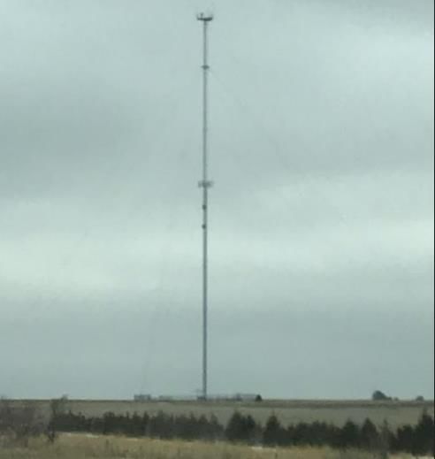
viii

                                    ACKNOWLEDGMENTS

        I would like to express my gratitude for the opportunity given to me by Dr. David

Eisenmann, and Dr. Simon Laflamme, and also for their support, encouragement, and direction

throughout the research. I also want to thank Dr. Jay Shen for being part of my committee

members, especially for his efforts and contributions to this work. It is appreciated.

       I would also like to thank my family, my parents, Vincent Twizeyimana and Jeanne

D’Arc Musabyimana, my brothers, Lambert Ngenzi, Boris Bugingo and Ghislain Bugingo, and

my sister Aimee Ingabire for always being there when I needed them, and also providing me

with their moral and financial support.

       And lastly, my thanks go to my colleagues and also the wonderful department faculty and

staff for making my time at Iowa State University a great experience.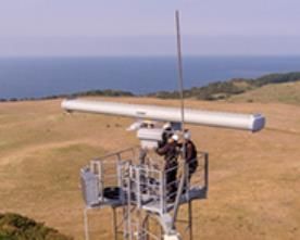
ix

                                            ABSTRACT

        The typical missions of rotorcraft involve flight paths at low altitudes. During low-

altitude flights, helicopter pilots are at risk of colliding with objects located close to the ground.

One of the highest contributing factors in helicopter accidents is a wire-strike. A study from FAA

showed that wire-strike accidents accounted for 5% of all aviation accidents. Wire-strikes occur

when a helicopter pilot hits wires, e.g., powerlines, cables, etc. Data from the National

Transportation Safety Board indicated that wire-strike was responsible for 95 helicopter

accidents, in which 100+ lives lost from 2005 to 2018. Many of these events occurred during

daylight, with good weather conditions.

        Due to the frequency of these events, several warning devices, such as laser, radar, and

database dependent systems, wire markers, etc., were developed to aid the pilot to the proximity

of wires. Despite such developments, wire-strike remains a serious threat to rotorcraft aviation.

        In this study, commercially available wire detection systems designed to increase

rotorcraft safety were reviewed. Their potential for detecting all wires and protecting aircraft in

the events of wire contact was evaluated. Based on these assessments, existing technologies were

found to be inadequate for preventing wire-strike events. Recommendations were provided on

improving current devices and developing a new sensor that meets the needs of rotorcraft flight

in an environment of wires. With the implementation of a wire strike protection and prevention

system in all rotorcrafts, wire-strike events will be significantly reduced by providing safer flight

missions and minimizing hazards in the flight path.
1
CHAPTER 1. INTRODUCTION
Problem Statement
Most of the helicopter (i.e., rotorcraft type) operations, such as agriculture spraying, law
enforcement, or search & rescue, inherently involve low level-flights. Missions such as these put
pilots at risk of striking objects, e.g., wires or other manmade structures, in their flight path. As
the use of rotorcraft is increasing in many applications, the number of rotorcraft events continues
to grow. One of the contributing factors to rotorcraft accidents is the wire-strike. According to
the FAA study, wire-strike events account for 5% of all aviation accidents from 1963 to present.
Wire-strike is a serious threat to rotorcrafts (ATSB, 2006; Nagaraj & Chopra, 2008; TSB
of Canada, 2013; Tuomela & Brennan, 1980). Database from the TSB of Canada indicated that
wire-strikes events represented 70% of all accidents from 2005 to 2013. In that same time frame,
the NTSB file showed 67 cases in the U.S. involving helicopters colliding with wires.
A study done by the ATSB from 2001 to 2010 ranked wire-strike as the primary cause of
accidents in agricultural activity, which accounted for 100 of 180 events reported (ATSB, 2013).
Studies also indicated that most wire strike accidents occurred during daylight in clear
weather conditions (ATSB, 2006; Barbara S. Reynolds, Rebecca H. Ivey, Parley P. Johnson,
1997; Nagaraj & Chopra, 2008). The average flying experience of pilots involved in those events
was over 2,000 hours, with an average age of 47.3-years (Nagaraj & Chopra, 2008).
In general, wires can be hard to see during daylight and tend to blend into the
background. Studies showed that pilots are aware of wire location before a strike. The ATSB
study showed that 63% of pilots striking wires were aware of their positions before collision
(ATSB, 2006). Because of the urgency of their missions, pilots tend to forget about them.2
Due to the frequency of these events, several technologies using laser, radar, and
database-dependent systems were developed to aid the pilot in the proximity of wires. Despite
such developments, wire-strike remains a serious threat to rotorcrafts. In this paper, existing wire
detection systems designed for rotorcrafts were investigated. With a good implementation of
wire-strike prevention systems in all rotorcrafts, wire-strike events can be significantly avoided
by providing safer flight missions to pilots and minimizing hazards in the flight path.
Research Objectives
The objective of this research was to study available technologies that were best fit for
reducing rotorcraft incidents. To accomplish the task, the team established the following tasks:
• Review existing sensors and detection systems (i.e., commercially available technologies
used to detect guy wires and other types of wires).
• Evaluate the potential of these devices and their applicability to various types of wires.
• Provide recommendations on how to improve the existing technologies and to develop a new
sensor system that meets the needs of pilots flying in an environment containing wires
Research Significance
The significance of this research is to increase rotorcraft safety during missions of pilots
involving low altitude flight. This research will illustrate the lack of or shortcomings of existing
sensors and detection systems designed for wire strike prevention in rotorcrafts. The thesis will:
• Provide the FAA with a better understanding of the needs of rotorcraft for safer flights.
• Show areas of currently available technologies that are lacking.
• Illustrate the criteria of a new sensor system design should include providing safer flights for
pilots and passengers.3
• Outline what is needed to meet the goal of the FAA to reduce significantly the number of
rotorcraft accidents involving wire-strike.
Data Sources and Methodology
To illustrate the needs for the research, the team compiled data on wire-strike events from
2005 to 2018 through the NTSB website. Information on each case was reviewed and then
summarized. The data includes the number of injuries, aircraft involved, etc. In addition, if an
aircraft was equipped with a device aboard, the type of device was recorded.
Once data on wire strike events was complete, available technologies used for wire
detection were investigated. The team contacted each manufacturer to obtain information about
their products. Most manufacturers shared their product brochure that contains information, i.e.,
system technical specifications and installation procedures. Other product information was
collected online. Next, the team reviewed the system's capabilities of detecting all wires, studied
how these devices worked (i.e., understand their sensing mechanism and how they interact with
the aircraft and pilot), and identified their shortcomings. The systems studied include laser and
radar, database-dependent systems, etc. With this information gathered about the devices, the
systems were evaluated against each other using a table that showed their abilities. Color-coded
in the table was used to contrast the technologies: Green=Good, Yellow=Fair & Red=Poor.
Organization of the Thesis
The thesis paper is organized as follows. Chapter 1 describes the problem statement,
objectives, and methods used to conduct the study. Chapter 2 presents wire strike accidents
involving helicopters, pilot's flying experience, and pilot needs. In Chapter 3, current wire
detection systems with their limitations are discussed. Chapter 4 provides a summary of findings
and recommendations and proposes future work for the design of a new sensor. Lastly, Chapter 5
concludes the study and provides guidance for future work to meet the FAA goal.4
CHAPTER 2. WIRE-STRIKE ACCIDENTS DATA ANALYSIS
The following section describes the analysis of data on helicopter wire-strike accidents
from 2005 through 2018. This includes but is not limited to the number of helicopters involved
in wire-strike accidents, the model/type aircraft involved, causes of accidents, and the age of
pilots and their flight experience.
Overview of Wire-Strike Accident
From 2005 to 2018, a total number of 95 accidents involved helicopters colliding with
wires, such as cable wire, guy wire, electrical transmission line, and other wires types. Of the 95
reported accidents, 28 of which were fatal accidents. Figure 1 shows the number of helicopters
involved in wire strike accidents per year. The number of accidents per year varies between 2
and 11, with an average of 6.8. Figure 1 also indicates that the number of helicopters engaged in
Total accidents Fatal accident
12
10
Number of helicopters
8
6
4
2
0
2005 2007 2009 2011 2013 2015 2017
year
Figure 1. Number of wire-strike accidents per year from 2005 to 2018
fatal events fluctuated from 0 to 4 and corresponds to a mean of 1.1.5
Table 1 presents the captured data due to wire-strike accidents. Between 2005 and 2018,
28 of fatal accidents resulted in 54 people losing their lives. In all 95 helicopter accidents, 68
people had fatal injuries, 37 received serious injuries, and 81 escaped with either minor or no
injuries.
Table 1. Number of wire-strike accidents that occurred between 2005 and 2018
Event Total Fatal Fatal Serious Minor No
date accidents accident injury Injury injury injury
2005 10 1 4 9 5 2
2006 8 2 8 8 0 0
2007 2 1 3 1 0 0
2008 6 4 9 0 0 2
2009 11 3 9 3 0 10
2010 8 2 7 3 6 5
2011 6 1 1 0 4 10
2012 8 3 10 3 3 0
2013 8 4 7 4 1 2
2014 8 5 6 1 4 2
2015 6 0 0 2 4 7
2016 3 0 0 1 1 1
2017 5 1 1 0 3 1
2018 6 1 3 2 6 2
Total 95 28 68 37 37 44
The major causes for these accidents were helicopters striking power lines (70), of which 18
were fatal events. Guy wires accounted for 8, in which four led to fatal accidents, and 20
involved static wire (including unmarked cables) in which six passengers aboard aircraft died.
Figure 2 shows a comparison between the numbers of accidents for two decades. From
1994 to 2004 (Nagaraj & Chopra, 2008) and from 2005 to 2015, the number of accidents because
of wire strike decreased by 34.68%. Minor injuries between both periods of years were down by
35.71%. Although the number of serious injuries decreased by 24.4%, the rate of fatalities per
wire-strike between these two periods increased by a difference of about 0.266. This indicates6
that for every helicopter involving collision with a wire, there is a high chance for the event to
result in fatalities.
2005-2015 1994-2004
Fatal injuries
Serious
injuries
Minor injuries
Total
accidents
0 20 40 60 80 100 120 140
Accidents
Figure 2. Comparison of wire-strike accidents between two decades
Wire-Strike Accidents by Operation Category
Wires are the most dangerous things in pilots’ eyes because they are extremely difficult
to identify from a distance. Moreover, the color of the wires tends to hide in the sun’s glare (see
Figures 15 and 16), making it difficult for pilots inside the cockpit to spot.
Figure 3 shows the number of accidents per operation type from 2005 to 2018. Of the 95
accidents analyzed, General Aviation (GA) accounted for 50, agricultural operations involved in
nearly 32 of all accidents, and Air Taxi& Commuter, Public Aircraft, and Rotorcraft Eternal load
accounted for 7, 4, and 2 accidents, respectively.7
General Aviation Agricultural Air Taxi & Commuter
Rotorcraft External Load Public Aircraft
9
8
Number of helicopter accidents
7
6
5
4
3
2
1
0
05 06 07 08 09 10 11 12 13 14 15 16 17 18
Year
Figure 3. Number of accidents by operation type
Figure 4 illustrates the number of wire accidents involving helicopter wire-strikes in both
agricultural activities and general aviation. Helicopters engaged in agriculture occupy second
place in the number of wire strike accidents. From 2005 through 2018, agriculture activities were
responsible for 32 (34%) of 95 accidents while general aviation was nearly 53 percent of all
accidents, with the other 13% caused by other types of accidents and as illustrated in Figure 5.8
General Aviation Agricultural
9
8
7
Number of accidents
6
5
4
3
2
1
0
2005 2007 2009 2011 2013 2015 2017
Year
Figure 4. Accidents occurred in general aviation and agricultural operations
Rotorcraft External Load Public
2% Aircraft
4%
Air Taxi & Commuter
7%
Agricultural
34% General Aviation
53%
Figure 5. Accident distribution per operation category
Helicopter Model Involved in Wire-Strike
Table 2 presents the number of aircraft types engaged in wire-strike from 2005 and 2018.
Robinson R44 and its variant R22 accounted for 30 of all accidents, Bell 206B and its variants
were involved in 19 accidents, Bell 47G and its variants accounted for ten accidents, with other
models accounting for 36 of the 95 rotorcraft accidentsTable 2. Rotorcraft type involving in wire-strike accidents
Type Aircraft 2005 2006 2007 2008 2009 2010 2011 2012 2013 2014 2015 2016 2017 2018 Total
Robinson R22 Beta 1 1 2 1 2 1 8
Aerospatiale AS 355F2 1 1
Aerospatiale AS350-B2 1 1
Aerospatiale AS350B 1 1
Bell 206 2 1 1 1 5
Bell 206B 1 1 3 1 2 4 12
Bell 206L-3 1 1 2
Bell 47G 2 1 3
Bell 47G-2A 1 1 1 3
Bell 47G-4A 1 1 2
Bell Oh 58A 1 1
Bell 222 1 1
9
Bell 47G 5 1 1 2
Bell Oh 58 1 1 2
Bertram William J
1 1
Bertram 2000
Brantly Helicopter B2B 1 1
Eurocopter Ec 130 B4 1 1
Eurocopter France
1 1
AS-350-B2
Garlick Helicopters
1 1
Inc OH-58C
Hiller UH-12E 1 1 2
Hughes 269A 1 1 2
Hughes 369D 1 1 1 1 4
Hughes 369E 1 1Table 2. Continued
Type Aircraft 2005 2006 2007 2008 2009 2010 2011 2012 2013 2014 2015 2016 2017 2018 Total
Hughes OH-6A 1 1
Hughes 269B 1 1 2
Hughes 369 1 1 1 3
Hughes OH-6A 1 1
MD Helicopter
1 1
Inc MD 900
MD Helicopters
1 1
Inc 369E
Robinson R44 1 1 1 3 1 1 3 3 3 3 2 22
Schweizer 269 C-1 1 1 2
Sikorsky S-55B 1 1
Texas Helicopter
1 1
10
Corp Oh-13E/M74
Texas Helicopter
1 1
Corp Oh-13H/M74A
PIASECKI/PIKE PV-18 1 111
Figure 6 shows the distribution of the total accident. 31.58 percent of the cases involved
Robinson models, Bell 206 accounted for 20.00% of the accidents, and Bell 47G and other
models accounted for 10.5% and 37.89%, respectively.
Bell 47G, 47G-2A, Others,
47G-4A, 47G-5, 37.89%
10.5%
Bell 206, 206L-
3, 206B, 20.00%
R22 & R44,
31.58%
Figure 6. Distribution of wire-strike by aircraft type
Helicopters Equipped with Onboard Devices
Of the 95 helicopter accidents filed in the NTSB dataset, 18 (18.9%) were equipped with
some form of protection and onboard warning systems. Ten out of the 18 helicopters were
equipped with onboard devices, but this resulted in fatal accidents. The other 77 accidents
reported no indication of devices aboard aircraft (National Transportation Safety Board, n.d.).
Table 3 depicts all the helicopters that were equipped with some sort of device aboard the
aircraft.12
Table 3. Aircraft type involved in wire-strike equipped with safety devices aboard
Registration # Aircraft Type Devices
N16673 BELL 206B maps & marker balls
N2011A SCHWEIZER 269 C-1 Garmin GPSMAP 496
N207DS BELL 206L 3 Infrared camera (IR), GeoStamp+
N263CH BELL 206B Wire cutters
N2877F Bell 206B Wire cutters
N368PD HUGHES OH-6A Spectrolab Nightsun SX-5 searchlight
N369AW HUGHES 369D WSPS, Garmin GPSMAP 496
N4191A HUGHES OH-6A GPS unit
ROBINSON HELICOPTER
N428JG R44 Digital map
N469E HUGHES 269B Garmin GPSMap 296
N484AE BELL 206 Wire cutters
Garmin III GPS, WSPS, Trimble TNL 1000
N5016U BELL 206B GPS
N7089J BELL 47G 5 AgNav Guia P152 GPS
ROBINSON HELICOPTER
N7189W R44 Radar Altimeter
N729DP AEROSPATIALE AS350B DataToys (Flight Recorders)
MD HELICOPTERS INC
N765WH 369E A hand-held GPS receiver
N8533F BELL 206 WSPS, Garmin GPSMap 496 handheld GPS
N992AA BELL 222 Garmin GNS 430, radar altimeter
As shown in Table 3, six models involved in wire-strike accidents were equipped with a wire
strike protection system, 4 of which resulted in 8 fatal injuries while four people received either
serious or minor injuries. 6 other helicopters involved in these events had installed onboard
Garmin warning devices. Other devices are provided in Table 3 above.
Number of Pilots Involved in Wire-Strike Accidents between 2005 and 2018
Figure 7 shows the age ranges of pilots who engaged in all wire-strike events, while
Figure 8 shows their flight time experience. Many pilots involved in wire-strike accidents were13
over 50 years of age, with a flying experience of over 2,000 hours. The average age of pilots was
about 46.5 years, along with a flying experience of approximately 5,046.9 hours.
30
25
20
Frequency
15
10
5
0
60
Ages
Figure 7. The age ranges for pilots involved in all strike cases
60
50
40
Frequency
30
20
10
0
2000
Flight ime (hrs)
Figure 8. Flying experience of pilot involved in all strike events14
Fatal Accidents Investigation
In the year between 2005 and 2018, the number of fatal helicopter accidents was 28, of
which 54 people lost their lives. Figure 9 shows the number of fatal accidents due to wire-strike
from 2005 to 2018. For the this13-year period, the highest number of toll deaths was three for
2008, 2009, 2012, 2013, and 2014. A high number of deaths was found to be in flights conducted
under general aviation. In the years 2015, 2016, and 2018, no fatal accidents were reported.
General Aviation Agricultural Air Taxi & Commuter
Rotorcraft External Load Public Aircraft
4.5
4
3.5
Number of accident
3
2.5
2
1.5
1
0.5
0
05 06 07 08 09 10 11 12 13 14 15 16 17 18
Year
Figure 9. Fatal accident by operation type
The pie chart illustrates the distribution of fatal accidents by operation type in Figure 10. The
general aviation operations accounted for 68% of fatal accidents, while agricultural activities
accounted for 10%. Public aircraft and Air Taxi & commuter were responsible for 11% of all
lethal events.15
Rotorcraft Public Aircraft
External Load 11%
0%
Air Taxi & Commuter
11%
Agricultural
10%
General Aviation
68%
Figure 10. Distribution of fatal accident by operation type
Table 4 shows the number and types of helicopters that engaged in fatal accidents from 2005 to
2018. Robinson R22 and R44 were responsible for 4 and 7, respectively. Three fatal accidents
involved Bell 206B model. Table 5 showed all aircrafts types which resulted in fatalities.
Table 4: Helicopter model resulted in fatal accident
Aircraft 200 200 200 200 201 201 201 201 201 201 201 201 201
2007
type 5 6 8 9 0 1 2 3 4 5 6 7 8
Robinson
1 1 1 1
R22 Beta
Aerospatial
1
e AS350B
Bell 206B 1 2
Bell 206L-
1
3
Bell 47G 5 1
Hughes
1 1
269A
Hughes
1 1
369D16
Table 4. Continued
Aircraft 200 200 200 200 200 201 201 201 201 201 201 201 201 201
type 5 6 7 8 9 0 1 2 3 4 5 6 7 8
Hughes
1
OH-6A
Hughes 26
1
9B
Robinson
1 1 1 2 1 1
R44
Schweizer
1
269 C-1
BELL 47
1
G5
Sikorsky
1
S-55B
Bell 222 1
PIASECK
I/PIKE 1
PV-18
As depicted in Figure 11, Robinson R22 and R44 models were responsible for about 39.29% of
fatal cases, while Bell 206 and its variants involved 14.29%. Hughes 369D and Hughes 268A
and its variants accounted for 7.14% and 10.7%, respectively.
Others,
28.57%
Hughes
369D, 7.14%
Hughes
269A, 269B,
10.7%
Bell 206L-3, R22 & R44,
206B, 39.29%
14.29%
Figure 11. Distribution of wire-strike by aircraft type involved in fatal accidents17
Table 5 presents the number of helicopters that were equipped with onboard devices but resulted
in fatal accidents. Five helicopters involved in wire-strike used Garmin systems.
Table 5. Aircraft type with onboard devices that resulted in fatal accidents
Registration Aircraft type Devices onboard
N992AA BELL 222 Garmin GNS 430, radar altimeter
N2011A SCHWEIZER 269 C-1 Garmin GPSMAP 496
N207DS BELL 206L 3 Infrared camera (IR), GeoStamp+
N368PD HUGHES OH-6A Spectrolab Nightsun SX-5 searchlight
N369AW HUGHES 369D WSPS, Garmin GPSMAP 496
N469E HUGHES 269B Garmin GPSMap 296
N5016U BELL 206B Garmin III GPS, WSPS, Trimble TNL
1000 GPS
N7089J BELL 47G 5 AgNav Guia P152 GPS
N7189W ROBINSON HELICOPTER R44 Radar Altimeter
With the altitude of accidents reported in the NTSB dataset, 25.0% of all accidents occurred at a
flight altitude of fewer than 50 feet, flight heights between 50 feet and 150 feet accounted for
66.6% of all accidents, 8.33% of accidents occurred at flight altitude above 150 feet.
Profile of Pilots Engaged in Fatal Wire-Strike
Of the 95 helicopter accidents investigated, twenty-eight were fatal events. Sixty-four
percent of accidents occurred in clear weather conditions with good visibility. Figures 12
through 13 show the age ranges along with flight history times of pilots. The average age of
pilots involved in those events was about 46.8 years, with a flying experience of about 4835.9
hours.18
12
10
Frequency 8
6
4
2
0
60
Age ranges
Figure 12. Ages ranges of pilots engaged in fatal accidents
16
14
12
10
Frequency
8
6
4
2
0
2000
Figure 13. Flight experience of pilots involved in fatal accidents
Flight time (hrs.)
With the known data reported on phases of flight history, 63% of all accidents occurred
while pilots were in the maneuvering phase, 18 percent of the cases were caused by pilots
cruising in low altitude, and take-off combined with climb constituted 13% of all cases. At the
same time, the approach phase was approximately 6% of all accidents (see Figure 15).19
Approach
Cruise
Take-off 6% 18%
8%
Climb
5%
Maneuvering
63%
Figure 14. Phases of flight by strike category
Probable Causes of Wire-Strike Accidents
Common issues identified in wire-strike accidents that occurred between 2005 and 2018
were associated with the following reasons:
• Failure to maintain clearance with wires (48)
• Failure to maintain adequate visual lookout (17)
• Failure to see and avoid a wire (12)
• Failure to maintain proper altitude (5)
• Other reasons include improper pilot decision to fly at low altitude, depart under VFR, (13)
Types of Wires of Concern
More than five million miles of wires are spread throughout the United States of America
territories. As depicted in Figure 15, transmission wires such as electrical power lines are
commonly abundant in the airspace. They can be carried out up to a mile between supports, e.g.,
pylon, which vary in heights from 15 feet up to 1000 feet above the ground (McPartland & F,
1987). Telephone or fiber optics lines are other transmission lines that pilots need to watch for
during flights. Like power lines, they span between support, e.g., towers, post lines, with varying
heights. Such means of distribution can pose a serious threat to helicopters operating in altitudes20
close to the ground. Because the nature of helicopter missions requires low-level flying, pilots
are at risk of hitting these objects, e.g., transmission wires, guyed lines, and towers present in
their flight trajectory.
Figure 15. Powerline, Highway 35, and Cambridge
Other wire types of interest are guy-lines, as illustrated in Figure 16. Guy wires are
attached to a structure for stability. Guy lines are tension cables that are anchored to towers or
pylon and into the ground. The length of a guy wire can extend outward up to a half-mile,
depending on the structure's height.
Figure 16. Communication tower guy-wires, I-35 West21
Data obtained from the NSTB revealed that ninety-five of wire-strikes took place
between 2005 and 2018, power transmissions line accounted for 74% of all cases, cables
constituted about 5% of all accidents, and nearly 8% involved guy wires. Static and fiber optics
represented 13% of all events, as shown in Figure 17.
Guy wire
8% Cable
5% Static or
fiber optic
line
13%
Power lines
74%
Figure 17. Distribution of strike by wire type
Summary of Wire-Strike Accidents
• From 2005 to 2018 there was a total number of 95 helicopters reported due to wire-strike
events, 28 of which were fatal accidents
• Of the 95 accidents recounted, 68 people were fatally injured, 37 received serious injuries,
and 81 others escaped with either minor or no injuries
• Agricultural operations were responsible for 34% of all wire strike accidents, 3 (10%) of
which were fatal accidents
• Eighteen out of 95 helicopters involved in wire-strike accidents were equipped with some
form of safety devices on board. Despite these devices installed aboard the aircraft, 10 out of
18 resulted in fatal accidents.22
• Out of 95 incidents reported, 9.47% of rotorcrafts operating under General Aviation were
equipped with some form of safety systems to aid pilot of the hazard, while in agricultural
activities, only 2.11% of the aircraft was equipped with some sort of detection systems
• With the known altitude of the accident reported in the NTSB dataset, it was found that:
o 25% of fatal accidents occurred at flight level below 50 feet
o 66.6% took place at flight altitudes between 50 feet and 150 feet
• Also, with the reported phase of flight history, 63% of accidents occurred in the maneuver
phase
• Powerlines were the major causes of accidents and accounted for 74% of all wire-strike
accidents between 2005 and 2018.
• The data file from NTSB also revealed that the average age of pilots engaged in fatal
accidents was 46.8 years with an average flying experience of about 4835.9 hours.
• 64.28% of fatal accidents occurred during daylight, clear weather with visibility greater than
five miles, and most of these operations were conducted within visual flight rules.
• The main causes associated with these accidents were identified. For instance, twenty-nine of
wire-strike cases involved the failure of the pilot to maintain an adequate visual lookout and
failure to see and avoid a wire.
• The NTSB report on wire strike showed that many accidents could have been prevented if all
rotorcrafts were equipped with some form of devices aboard the aircraft to increase the
pilot’s situational awareness of obstacles nearby.
Nature of Helicopter Flights
Data gathered on helicopter wire-strike accidents from the NTSB indicated that the nature
of helicopter missions involves various operational regimes, e.g., hover, sideward or reverse23
flight, and forward flight. Hence, suitable devices should provide warnings to pilots if a wire is
close to the aircraft for all different phases of rotorcrafts flights.
Rotorcraft Pilots Need to Fly Safely
Due to the nature of helicopter missions, sensor systems to be recommended or
developed should satisfy the following criteria below:
• Be capable of detecting all types of wires
• Provide both optical and acoustic alerts
• Detect wire around the rotorcraft in any direction (within 50 feet envelope as required by
the FAA)
• Indicate the location of obstacles with reference to the rotorcraft.
• Preferably sensors that do not require obstacle information.
• Not be affected by weather (e.g., fogs, clouds, rain…)
• Reduce pilot workload
• **Be affordable for all civil helicopters24
CHAPTER 3. WIRE-STRIKE EXISTING TECHNOLOGIES
The following section describes currently available warning systems designed to assist
pilots in avoiding collisions between aircraft and obstacles such as wire cables when their
missions require low-level flights and including their shortcomings.
Powerline Detection System (PDS)
The PDS is a system that alerts a pilot if an aircraft is in the vicinity of active power lines
(Greene & Greene, 1999). The system uses basic radio techniques to sense the presence of
electromagnetic fields (EMF) emitted from lines (Greene & Greene, 1999). An audio signal
indicates the existence of power lines via the pilot’s aircraft audio system and a visual signal.
The system, however, will not alert a pilot if lines do not generates electric fields at power line
frequency (Craig, 2016a). Such lines include unpowered lines, guy wires, static lines or cables.
In addition, equipment that run on DC power, e.g., radio towers communication, will not be
alerted by the system.
The PDS is based on the concept that when power lines operate at alternating current
(AC) power, an electric and magnetic field is produced. For instance, power lines in the United
States of America use 60 hertz (Hz), while in Europe use 50Hz. Both fields consist of a very low
frequency on the electromagnetic spectrum, which can be detected. Consequently, Safe Flight
designed the PDS system for detecting the electrical component of the two fields. The main
components of the PDS system are a Powerline Detector unit, a whip antenna, an antenna
coupler, and their connecting wires.
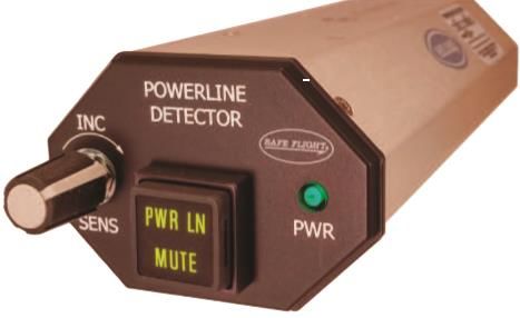
The Powerline Detector (PLD) is the main part of the PDS system (see Figure 18). It is
mounted on the aircraft’s instrument panel, within a pilot’s reach, see Figure 18. The PLD acts
both as a display unit and receiver. The PLD display is available in two configurations. The PLD25
contains the system functions, such as a sensitivity button for adjusting the receiver's sensitivity,
an amber mute text for showing whether or not the audio signal is muted, and an alert text on the
front panel of PLD for indicating the presence of a power line.
Figure 18. Powerline Detection System main unit (Craig, 2016a)
The PLD receiver is a passive detector that uses narrow tuned receivers to respond to AC
signals of 50Hz and 60Hz. It is directly connected to an antenna. A typical specification of the
PLD is included in Table 7. The system operates in the frequency range between 0.2 and 11kHz
(Greene and Greene, 1999). Since different frequency signals are detectable at the antenna, the
PLD receiver is built with band-pass filters, which allow only frequencies generated at power
line frequency and block all other frequencies. Hence, the PLD receives radio signals from the
antenna and then drives these signals into audio output to warn a pilot of a potential danger in the
aircraft flight path.
For picking up AC signals emitted from power lines, an antenna is fixed on the aircraft's
exterior airframe. At 60 Hertz, the required electrical antenna corresponds to a wavelength of
5,000km, which is not feasible to be fixed on the helicopter. However, Safe Flight uses a whip
antenna that does not follow the antenna theory. The whip antenna used is a quarter-wave
antenna, which consists of small capacitors connected to the PLD receiver. This type of antenna
is also known as “short antenna,” which requires very high impedances at 50Hz or 60Hz fields,
meaning the impedance of the antenna for both fields would have to match the PLD receiver. In26
order to maximize the power transfer from the receiver and the antenna, the coupler is attached
to the whip antenna. This allows supplying the correct impedance matching of the antenna and
the receiver.
The short antenna is characterized by a ground plane antenna; therefore, the full body of
an aircraft becomes an essential part of the antenna. The airframe of the aircraft acts like an
electrical ground plane for the antenna in free space. Prior to antenna installation, Safe Flight
performs an ‘electromagnetic field modeling’ test on the aircraft body to determine the antenna
location.
Since an aircraft can approach a power line from any direction, the antenna sensor of the
system is omnidirectional. This means that the system will still warn the pilot even if a wire is
located behind an aircraft.
The PDS gives warnings using audio and visual signals. For instance, when a pilot is
flying near the location of power lines, the system senses energy given off from the line, which
triggers an audio sound to alert a pilot of a power line nearby. The audio signal is heard through
aircraft’s audio system. The audio sound produced by the system is a sequence of clicks that
sound like a Geiger-counter. The nearness of a power line is indicated by an increase in the
volume sound of the system. As a backup to the audio signal, a warning lamp indicator is
activated. Depending on the PLD configuration used, a red “WARN” or amber “PWR LN” light
text is displayed for a pilot. With mute control on the unit, a pilot can turn off the sound if
desired. When the system's audio output is muted, the warning lamp will remain on as an
indication of a power line nearby. In addition, a sensitivity knob for the detector enables a pilot
to adjust the receiver sensitivity when working in places with low level of line fields, e.g., close27
to the ground or congested areas. Safe Flight recommends the knob for sensitivity to be set at the
maximum level when operating in unknown territories.
The distance from which a power line is sensed depends on the voltage in the
transmission line. For example, power lines with low voltage can be sensed between 500 and
1000 feet, while electrical transmission lines with high voltage can be detected up to a ½ mile
(Craig, 2016b). Yet, for each aircraft, the distance from which a wire is detected can vary due to
antenna installation on the aircraft body.
The system does not provide the location of wire sensed with reference to an aircraft.
However, it gives a pilot enough time to identify the hazard in the path of flight visually. The
PDS is claimed to increase pilot reaction time from 10 to15 seconds (Craig, 2016b) from the first
scan. The system can be deployed for missions conducted at nighttime. The cost of PDS is
estimated at around $12,500 (Chandrasekaran et al., 2020).
The following are some of the advantages and disadvantages of the PDS to consider:
Advantages:
• Detect only obstacles that radiate electric field at power line frequency
• All-weather conditions
• Simple, lightweight, and easy to install
Limitations:
• Cannot detect lines that do not carry current, e.g., guy wires, unpowered lines, cables, etc.
• Cannot detect equipment that operates at DC power, such as radio towers.
• Cannot provide the location of the power line with reference to the aircraft
• The strength of the field determines the distance at which a wire can be sensed.28
Obstacle Warning System (OWS)
Obstacle Warming Systems are laser-based technologies intended to provide a flight crew
with safe flight missions carried out the near-earth ground. The OWS warns pilots of the danger
of collision between obstacles and aircraft ahead of the flight. The systems can detect objects,
such as small wires, guy wires, or cables, and various structures located up to distances of a mile
(Ramasamy et al., 2016; Sabatini et al., 2015). They provide warnings to a pilot utilizing optical
and acoustic alerts. Commercially available OWSs for helicopters are Laser Obstacle Avoidance
Marconi and Helicopter Laser Radar.
Helicopter Laser Radar (HELLAS)
The HELLAS is a laser-based obstacle warning system (Davis & Centolanza, 2003) for
scanning objects ahead of the helicopter flight trajectory, and it presents detected obstacles to a
flight crew if there is a threat along the aircraft trajectory. It can produce a 3D image of an object
in real-time. The two available versions of HELLAS (Bers et al., 2005; Seidel et al., 2008, 2006)
are HELLAS-Warning (HELLAS-W) and HELLAS-Awareness (HELLAS-A). Both systems
give warnings to a pilot through an audio and visual alert. Of these two systems described,
HELLAS-A is the most advanced system, and it is used in many military applications and is also
available for civil applications. The current civilian version of HELLAS-A is called Sferisense
500. Its main components are the sensor head unit (SHU) and control panel unit.
The SHU of Sferisense 500 is illustrated in Figure 19. The sensor system is mounted
under an aircraft’s nose and connected to an aircraft navigation system and intercom system
(Seidel et al., 2006). The SHU consists of a laser transmitter for emitting pulses of light, a
receiver (or avalanche photodiode) for receiving a light beam bounced off from an object, and an
oscillating mirror that performs a horizontal scan axis. The sensor head scans every object
around an aircraft in the forward flight direction of the aircraft. The sensor scans object using a29
field of view of ±18° in the horizontal direction and ±21° in the vertical direction. The scan field
of view of the system can be adjusted by ±12° in both the vertical and horizontal directions
[(Seidel et al., 2008), centered on its axis.
Figure 19. The HELLAS SHU (Münsterer et al., 2014)
The pulsed laser of the sensor system operates at an eye-safe solid-state diode-pumped
erbium fiber laser of about 1.54-m, utilizing a peak power of 15kW (Seidel et al., 2006). A
typical specification of the sensor system is provided in Table 7. The sensor head of the system
transmits laser pulses with a repetition frequency of about 60 kHz to scan the aircraft flight path
and analyses the pattern of laser lights reflected from objects at its optical sensor head. The scan
pattern produced by the sensor head consists of vertical and horizontal lines for generating a
three-dimensional representation of an object in real-time using two-axis scanning laser radar.
An oscillating mirror performs the vertical scan while the horizontal scan is carried out by a fiber
optical scanner (Seidel et al., 2006). The scan per frame rate of the system is 3Hz.
Because the HELLAS sensor captures every single object in the front of an aircraft, the
HELLAS system is built-in advanced algorithms (Seidel et al., 2006) to classify isolating and
prioritize detected obstacles like wires, trees, or building in order to provide only relevant
information to a pilot. HELLAS systems algorithms [2] group all objects captured and classifies
them based on their shape and types to accomplish this task. For example, wires in the HELLAS30
system are categorized as thin objects. More details about obstacle classification are provided in
(Seidel et al., 2008). In order to trigger warnings, the HELLAS system performs an analysis for
risk level on detected obstacles to alert a pilot on time.
The distance to objects detected is calculated using time of flight measurement of the
pulsed laser, which is when it takes for a light beam to travel from the sensor head to the object
and back from the object to the detector, i.e., HELLAS SHU. With flight state information
received from an aircraft navigation data bus (ARINC 429), the echo range is computed.
Obstacle information is superimposed on the aircraft cockpit’s Multi-Function Display (MFD)
(Seidel et al., 2008) for a pilot to see. However, the operating range of the sensor head is
restricted to 50m to 1.2km.
If a course of the aircraft indicates there will be a threat along the aircraft’s flight path
that a pilot should be aware of, the HELLAS system overlays obstacle information on the MFD.
As an additional means of warning, the HELLAS system provides an audio alert to a pilot via the
aircraft’s intercom system if necessary.
The HELLAS can be controlled and given commands from aircraft interfaces via avionic
bus (MBUS-1553B or Ethernet). An optional Control Panel (CP) unit can be included, which is
mounted inside the cockpit, with a pilot’s reach. The CP enables a flight crew to give commands
to the system functions, e.g., range selections, warning, or display (Bers et al., 2005).
The HELLAS sensor system has a large range of detection obstacles. It can detect wires
with a detection probability of over 99.5% within a second. For instance, the system can detect
large objects located up to 1.2 km in good visibility. It can also detect a 5-mm diameter wire
from 725m in good visibility. However, the sensor system cannot detect objects within 50-meter
of an aircraft radius (Seidel et al., 2008).31
Laser Obstacle Avoidance Marconi (LOAM)
LOAM is another active obstacle warning system based on laser technology. It scans the
area in the front of an aircraft flight path using an eye-safe laser of 1.55-m. If there is a threat
along the aircraft course, LOAM displays information about the threat to a flight crew via
aircraft cockpit's MFD. The main components of LOAM are a sensor head unit, a control panel
unit, and an optional warning unit.
The LOAM uses the same principles as the HELLAS system. However, LOAM differs
from HELLAS sensors when it comes to scanning methods.
LOAM uses a palmer scan (Sabatini, Gardi, and Richardson 2014) instead of a raster
scan which is performed by the HELLAS (Schulz, Scherbarth, and Fabry 2002).
Figure 20. LOAM Sensor Head Unit (Sabatini et al., 2014)
Figure 20 shows the sensor head unit (SHU) of the LOAM system. It is installed under an
aircraft’s nose and connected to interfaces of an aircraft flight management system. The SHU
transmits the pulse of lights based on an eye-safe solid-state diode-pumped erbium fiber laser
with a peak power of 10kW (Sabatini et al., 2014). The laser pulse is emitted with a pulse
repetition rate of about 60 kHz to detect objects in the aircraft flight path. A basic specification
of the LOAM sensor is shown in Table 7. The sensor system scans objects in front of an aircraft,
in the forward flight motion (Sabatini, 2013). The LOAM sensor listens and analyses the pattern
of laser lights reflected from objects at the optical sensor head. The sensor scan has a field of32
view of 40° in azimuth and 30° in elevation. As an addition, the sensor FOV can be steered by
±20° in horizontal and vertical directions. The scan pattern performed by the LOAM sensor is an
elliptical pattern at a frame rate of 4x per second (Sabatini et al., 2014). This elliptical scan
produced by the LOAM scanner is also known as a palmer scan.
Just like the HELLAS system, the LOAM sensor scans all objects in the front of an
aircraft. With software algorithms built into the system (Sabatini et al., 2014), LOAM can
isolate, classify, and prioritize obstacles detected. Only relevant information is displayed to a
pilot on the unit device for warnings.
The range of obstacles detected is computed using the laser pulse time of flight.
Combined with flight data received from aircraft navigation data bus (ARINC 429), the echo
range is computed. Obstacle information is superimposed on the aircraft’s Multi-Function
Display (MFD) (Sabatini et al., 2014) for a pilot to see. If a threat becomes imminent, LOAM
offers an audio alert to a pilot via an aircraft’s intercom system.
Similar to HELLAS, LOAM is fully integrated into aircraft avionic systems. LOAM can
be controlled by the Control Panel (CP). It is placed inside of the cockpit, within a pilot’s reach.
The CP allows a flight crew to give commands to LOAM (Sabatini et al., 2014) if necessary.
LOAM has a great range of obstacle detection. For instance, the system can detect a large
object from a distance up to 2-km in good visibility. It can also detect a 5-mm diameter wire
located up to 620 meters in a visual range of 10km. However, the detection range of the system
is affected by weather conditions.
Both current OWS have proven to be deployed in uncharted regions, provide obstacles
information to a pilot in real-time, have a good detection range, and do not require a database of
obstacles. However, distance detection can be affected by fog, clouds, dust, rain, etc. The sensors33
systems have higher power consumption (see table 7). The cost of the current OWS is several
$100,000 (not including the additional cost of installation from the manufacturer).
The following are the advantages and disadvantages of these systems to consider.
Advantages:
• Can detect thin wires and other objects up to a mile
• Do not require obstacles database to operate
• Provide obstacles information in real-time
• Can be deployed in uncharted regions
Limitations:
• Expensive and heavy systems
• The detection range can be affected by weather, e.g., rain, clouds, and fog
• Minimum detection range is 50-meters
• Detect objects only in forward flight motion of the aircraft
• Narrow field of view
• Ambient temperature can cause the system not to work properly
Helicopter Terrain Awareness and Warning System (HTAWS)
The HTAWS are systems based on mapping databases designed to improve pilot
situational awareness when missions involve flights near terrain or obstacles. The HTAWS
provides information on terrain and obstacles on 2D displays units. The HTAWS is a modified
version of the current Terrain Awareness and Warning System (TAWS), known as forward-
looking terrain awareness, developed to prevent controlled flight into terrain (CFIT) accidents.
Current HTAWS include a wire database information or structures, such as buildings, towers,
and other human-made structures. Based on this information, the system can alert a pilot if there
is a danger of collision between an aircraft and obstacles.You can also read