WASTE HEAT RECOVERY SYSTEMS - FILIP GUSTAFSSON FUEL ENERGY UTILISATION FOR A MARINE DEFENCE PLATFORM - DIVA
←
→
Page content transcription
If your browser does not render page correctly, please read the page content below
Master of Science in Mechanical Engineering
 June 2020

 Waste heat recovery systems
c Fuel energy utilisation for a marine defence platform

 Filip Gustafsson

 Faculty of Engineering, Blekinge Institute of Technology, 371 79 Karlskrona, Sweden
This thesis is submitted to the Faculty of Engineering at Blekinge Institute of Technology in partial
fulfilment of the requirements for the degree of Master of Science in Mechanical Engineering. The
thesis is equivalent to 20 weeks of full time studies.

The author declare that they are the sole authors of this thesis and that they have not used any sources
other than those listed in the bibliography and identified as references. They further declare that they
have not submitted this thesis at any other institution to obtain a degree.

 Contact Information:
 Author: Filip Gustafsson
 E-mail: filip.gustafsson1@gmail.com

 University advisor: Ansel Berghuvud
 Department of Mechanical Engineering

 Faculty of Engineering Internet : www.bth.se
 Blekinge Institute of Technology Phone : +46 455 38 50 00
 ii
 SE-371 79 Karlskrona, Sweden Fax : +46 455 38 50 57
ABSTRACT
This report is a thesis for BTH in collaboration with the company Saab Kockums AB. In order to meet
future environmental and economical demands, a vessel must reduce its fuel consumption to have
smaller climate impact and save money.

Waste heat recovery systems (WHRS) captures the thermal energy generated from a process that is not
used but dumped into the environment and transfers it back to the system. Thermal energy storage
(TES) is the method of storing thermal energy which allows heat to be used whenever necessary.
Some applications of TES are seasonal storage, where summer heat is stored for use in the winter or
when ice is produced during off-peak periods and used for cooling later.

The purpose of this study is to investigate the possibilities of utilising a vessel’s waste heat by
converting thermal energy into electrical energy. This thesis also aims to investigate conditions for
SaltX Technology’s nano-coated salt as a potential solution for thermal energy storage.

Initially, the expectations and requirements a future WHRS were investigated in a function analysis.
Continuously, the method consisted of a combination of a literature review and dialogue with stake
holders. The literature review was used as a tool to identify, select and study concepts of interest built
on scientifically proven facts. Dialogues with stake holders were held as a complement to the literature
study to find information.

The study showed that an organic Rankine cycle has the highest efficiency for low-medium
temperature heat and is therefore most suitable to recover thermal energy from the cooling water. The
concept of a steam Rankine cycle is most suitable for recovering thermal energy from the exhaust
gases for direct use. The study obtained conditions and important properties for storing thermal energy
in salt for later use. Finally, the result showed that a Stirling engine is the most efficient concept for
conversion of stored energy into electrical energy.

The conclusions are that there are great possibilities for waste heat recovery on marine defence
platforms. A Stirling engine for energy conversion in combinations with thermal energy storage shows
most promise as a future waste heat recovery system on this type of marine platform.

Key words: Waste heat, Efficiency, Energy, Thermal energy storage, Marine

 iii
SAMMANFATTNING
Denna rapport är ett examensarbete för BTH i samarbete med företaget Saab Kockums AB. Arbetet
utforskar möjligheterna att möta framtida miljömässiga och ekonomiska krav genom att låta fartyg
minska sin bränsleförbrukning.

System för återvinning av spillvärme (WHRS) fångar upp värmeenergi som vanligtvis kyls ner eller
släpps ut i naturen och för den tillbaka till systemet. Termisk energilagring (TES) är metoder för
lagring av värme som gör det möjligt att använda termisk energi när det behövs. Vissa applikationer
av TES är säsongslagring, där sommarvärme lagras för användning på vintern eller när is produceras
under vintern och används för kylning senare.

Syftet med denna studie är att undersöka möjligheterna att utnyttja ett fartygs spillvärme genom att
omvandla termisk energi till elektrisk energi. Detta examensarbete syftar också till att undersöka
förhållandena för hur SaltX Technology’s nanobelagda salt kan användas som en potentiell lösning för
lagring av termisk energi.

Inledningsvis undersöktes WHRS:s förväntningar och krav i en funktionsanalys. Fortsättningsvis
bestod metoden av en kombination av en litteraturstudie och dialoger med intressenter.
Litteraturstudien användes som ett verktyg för att identifiera, välja och studera intressanta koncept
baserade på vetenskapligt beprövade fakta. Dialoger hölls som ett komplement till litteraturstudien för
att hitta information.

Studien visade att en organisk Rankine-cykel har den högsta verkningsgraden för låg-medelhög
temperatur och därför är bäst lämpad för att återvinna energi buren i kylvattnet samt att en ång-
Rankine-cykel är bäst lämpad för att utnyttja energin från avgaserna för direkt användning. Studien
erhöll förhållanden för termisk energilagring i salt samt viktiga parametrar för systemet. Slutligen
visade resultatet att en Stirlingmotor är det mest effektiva konceptet för omvandling av lagrad energi
till elektrisk energi.

Slutsatserna är att det finns stora möjligheter för återvinning av restvärme på marina
försvarsplattformar. En Stirlingmotor för energiomvandling i kombination med termisk energilagring
visar störst potential som ett framtida system för återvinning av spillvärme på denna typen av
plattformar.

Nyckelord: Restvärme, Verkningsgrad, Energi, Termisk energilagring, Marin

 iv
ACKNOWLEDGEMENTS
I would like to take some time thanking the people who have helped me through this degree project.

At first, Saab Kockums AB and Carl Snaar for your mentoring and the opportunity to be a part of
your team.

Filip Mattsson, Peter Nilsson and Karl-Axel Olsson at Saab Kockums AB for the guidance and
interesting discussions throughout the project.
Ansel Berghuvud who supervised the degree project through Blekinge institute of Technology.

Karlskrona, June 2020
Filip Gustafsson

 v
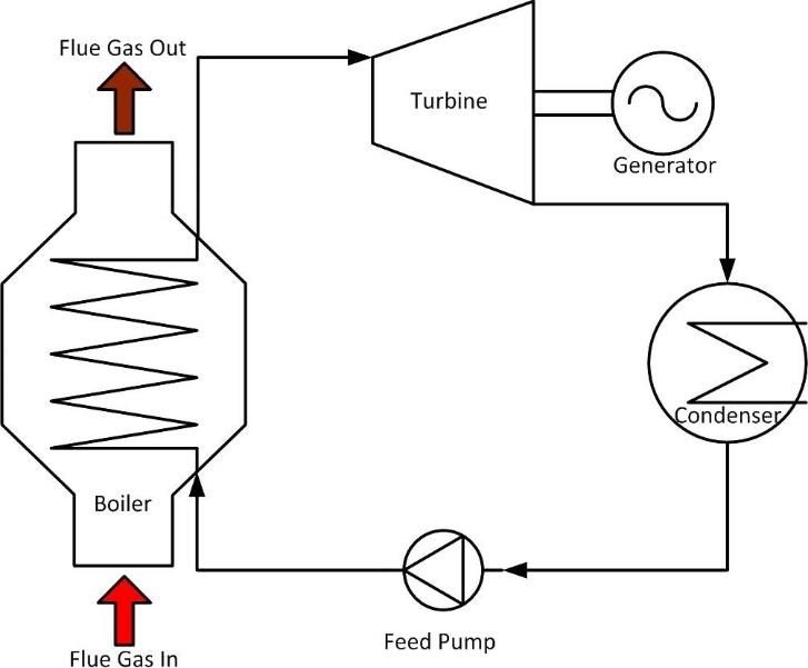
TABLE OF CONTENTS
 ABSTRACT ................................................................................................................................................ III

 SAMMANFATTNING ............................................................................................................................... IV

 ACKNOWLEDGEMENTS .........................................................................................................................V

 TABLE OF CONTENTS ........................................................................................................................... VI

 NOMENCLATURE ..................................................................................................................................... 3

 LIST OF FIGURES ...................................................................................................................................... 5

 LIST OF TABLES ........................................................................................................................................ 6

 1 INTRODUCTION ............................................................................................................................... 7

 1.1 PURPOSE OF THIS STUDY ................................................................................................................ 8
 1.1.1 Thesis questions ........................................................................................................................ 8
 1.2 LIMITATIONS ................................................................................................................................. 8
 1.3 ETHICAL AND SUSTAINABILITY ASPECTS ....................................................................................... 9
 1.3.1 Ethical aspects .......................................................................................................................... 9
 1.3.2 Environmental aspects.............................................................................................................. 9
 1.4 REPORT STRUCTURE AND APPROACH ............................................................................................. 9
 1.5 BACKGROUND ............................................................................................................................. 10
 1.5.1 Waste heat recovery systems .................................................................................................. 10
 1.5.2 Thermal energy storage .......................................................................................................... 11

 2 THEORY ............................................................................................................................................ 13

 2.1 THERMAL ENERGY STORAGE ....................................................................................................... 13
 2.1.1 Thermo chemical heat storage in salt ..................................................................................... 13
 2.2 CONVERSION OF THERMAL ENERGY............................................................................................. 14
 2.2.1 Rankine cycle .......................................................................................................................... 14
 2.2.2 Organic Rankine cycle ........................................................................................................... 16
 2.2.3 Stirling cycle ........................................................................................................................... 17

 3 METHOD ........................................................................................................................................... 20

 3.1 DIALOGUE WITH STAKE HOLDERS ................................................................................................ 21
 3.2 CURRENT SYSTEM CHARACTERISTICS .......................................................................................... 21
 3.2.1 Calculation of available thermal energy ................................................................................ 23
 3.2.2 Important properties of a waste heat recovery system ........................................................... 25
 3.3 THERMAL ENERGY STORAGE ....................................................................................................... 26

 vi
3.3.1 Identification thermal energy storage methods ...................................................................... 26
 3.3.2 Selection of thermal energy storage methods ......................................................................... 26
 3.3.3 Study of thermal energy storage in salt .................................................................................. 27
 3.3.3.1 Calculations of storage properties..................................................................................................... 29
 3.4 CONVERSION OF THERMAL ENERGY............................................................................................. 29
 3.4.1 Identification of concepts for conversion of thermal energy .................................................. 29
 3.4.2 Selection of concepts for conversion of thermal energy ......................................................... 30
 3.4.3 Concept study ......................................................................................................................... 32
 3.4.3.1 Direct conversion of energy .............................................................................................................. 38
 3.4.3.2 Conversion of stored energy ............................................................................................................. 39

4 RESULTS ........................................................................................................................................... 40

 4.1 THERMAL ENERGY STORAGE ....................................................................................................... 40
 4.1.1 Identification of thermal energy storage methods .................................................................. 40
 4.1.2 Selection of thermal energy storage methods ......................................................................... 40
 4.1.3 Study of thermal energy storage in salt .................................................................................. 40
 4.1.3.1 Calculations of storage properties..................................................................................................... 41
 4.2 CONVERSION OF THERMAL ENERGY............................................................................................. 41
 4.2.1 Identification of concepts for conversion of thermal energy .................................................. 41
 4.2.2 Selection of concepts for conversion of thermal energy ......................................................... 42
 4.2.3 Concept study ......................................................................................................................... 42
 4.2.3.1 Direct conversion of energy .............................................................................................................. 43
 4.2.3.2 Conversion of stored energy ............................................................................................................. 44

5 DISCUSSION ..................................................................................................................................... 46

 5.1 THERMAL ENERGY STORAGE ....................................................................................................... 46
 5.1.1 Identification of thermal energy storage methods .................................................................. 46
 5.1.2 Selection of thermal energy storage methods ......................................................................... 46
 5.1.3 Study of thermal energy storage in salt .................................................................................. 46
 5.1.3.1 Calculation of storage properties ...................................................................................................... 49
 5.2 CONVERSION OF THERMAL ENERGY............................................................................................. 49
 5.2.1 Identification of concepts for conversion of thermal energy .................................................. 49
 5.2.2 Selection of concepts for conversion of thermal energy ......................................................... 49
 5.2.3 Concept study ......................................................................................................................... 49
 5.2.3.1 Direct conversion of energy .............................................................................................................. 50
 5.2.3.2 Conversion of stored energy ............................................................................................................. 51

6 CONCLUSIONS ................................................................................................................................ 53

7 FUTURE WORK ............................................................................................................................... 54

8 REFERENCES .................................................................................................................................. 55

SUPPLEMENTAL INFORMATION ....................................................................................................... 59

 vii
8.1 APENDIX A. DATA FROM ENGINE MANUFACTURER ..................................................................... 59

 viii
Faculty of Engineering, Blekinge Institute of Technology, 371 79 Karlskrona, Sweden
NOMENCLATURE
 ∆ Reaction enthalpy (kWh/mol)
 Entropy (J/kgK)
 Ƞ ℎ Thermal efficiency (dimensionless)
 Ƞ Concept efficiency (dimensionless)
 Ƞenergy Energy efficiency (dimensionless)
 Ƞtemp Temperature efficiency (dimensionless)
 Ƞsystem Total system efficiency (dimensionless)
 Nominal engine power (MW)
 Fuel power (MW)
 Cold temperature source (K)
 ℎ High temperature source (K)
 Specific fuel consumption (g/kWh)
 Heat value (MJ/kg)
 Temperature (K)
 Pressure (bar)
 ℎ Thermal energy (MWh)
 Electrical energy (MWh)
 Product A (dimensionless)
 Product B (dimensionless)
 Product C (dimensionless)
 Available energy (MWh)
 Storage density (MWh/m3 )
 Storage density (MWh/ton)
 Density (ton/m3 )
 Required volume (m3 )
 Mass
 Tch Charge temperature (°C)
 Tdc Discharge temperature (°C)
 Stored energy (MWh)
 Required energy (MWh)

 3
Abbreviations
 EM Electric motor
 ME Main engine
 DG Diesel generator
 TES Thermal energy storage
 SHS Sensible heat storage
 LHS Latent heat storage
 CHS Chemical heat storage
 PCM Phase change material
 WHRS Waste heat recovery system
 SRC Steam Rankine cycle
 ORC Organic Rankine cycle
 TEG Thermo electric generator

 4
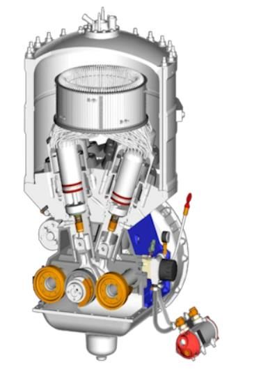
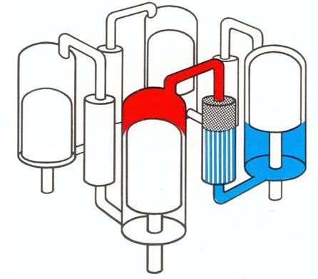
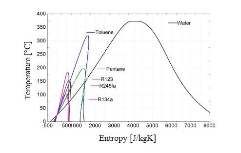
LIST OF FIGURES
Figure 1. Classification of thermal energy storage. [9] ......................................................................... 11
Figure 2. Principle of thermochemical heat storage [12]. ..................................................................... 13
Figure 3. The principle layout of the closed adsorption process [13]. .................................................. 14
Figure 4. A simple Rankine cycle configuration with main components [17]. ..................................... 15
Figure 5. A temperature - entropy diagram of the Rankine cycle, inspired by [18].............................. 16
Figure 6. Comparison of entropy for different working fluids. The figure is inspired by [20]. ............ 17
Figure 7. Pressure-volume diagram of the Carnot processes [23]......................................................... 18
Figure 8. Temperature-entropy diagram of the Carnot processes [23].................................................. 18
Figure 9. Pressure-Volume graph for the Stirling cycle [24]. ............................................................... 19
Figure 10. Intended structure of how the literature review was carried out. ......................................... 21
Figure 11. Example platform with propulsion and power generation. .................................................. 23
Figure 12. Researched and interpolated efficiencies of a steam Rankine cycle. ................................... 33
Figure 13. A double acting four cylinder alpha type Stirling engine from two perspectives [55]. ....... 34
Figure 14. The theoretical efficiency of a Stirling engine for different temperature differentials. ....... 35
Figure 15. An example installation of four Climeon modules [67]....................................................... 37
Figure 16. The salts energy storage capacity in relation to the volume and mass. ................................ 41
Figure 17. Possible operating temperatures for each concept. .............................................................. 43
Figure 18. Probable efficiencies for each concept................................................................................. 43
Figure 19. System for direct conversion of thermal energy. ................................................................. 44
Figure 20. System design for later conversion of heat. ......................................................................... 45
Figure 21. Data from engine manufacturer 1. ....................................................................................... 59
Figure 22. Data from engine manufacturer 2. ....................................................................................... 60

 5
LIST OF TABLES
Table 1. Waste heat sources from industries [5]. .................................................................................. 10
Table 2. Example of operating modes. .................................................................................................. 24
Table 3. Fuel and engine data for calculation of thermal energy. ......................................................... 24
Table 4. Summary of the daily available thermal energy. ..................................................................... 25
Table 5. Data for thermal energy storage in salt. .................................................................................. 40
Table 6. Properties of the salt to store available energy per day. .......................................................... 41
Table 7. System properties for direct use of thermal energy. ................................................................ 44
Table 8. Summary of system data for conversion for later use. ............................................................ 45
Table 9. Storage data to supply enough power to propel the vessel by electric motors for one day. .... 45

 6
1 INTRODUCTION
It has never been a more important topic than it is today when it comes to energy consumption. In
today's society, fossil fuels are the main energy source and are used in most vehicles such cars and
ships but also in power plants. Ships are of special interest here since that is the area this project will
focus on in more detail. Most modern vessels are diesel powered and the efficiency of a normal
combustion engine is approximate 40 %, which means that 60 % of the energy is lost, most of it in the
form of heat. According to the first law of thermodynamics, which refers to the conservation of
energy, the energy is indestructible and can only be transformed into other forms. This thesis is
relevant to the subject because it explores the possibility to utilise the available waste heat on a marine
platform and transform that thermal energy into electrical energy.

This waste heat recovery study is based on the fact that the vessels of interest are of military grade. At
this point, most of the heat is quickly cooled down to reduce the IR-signature of the vessel and
therefore increasing stealth properties of the vessel. If the thermal energy instead could be converted
and utilised as electrical power, the efficiency of the vessel would be improved and fuel consumption
reduced. The vessels range of service can be extended and possibly the IR-signature of the vessel
could be decreased even further. A working solution could also lead to smaller engines or less fuel
storage which in turn enables more storage space on the vessel. Although the thesis aims to recover
thermal energy for a military vessel, a waste heat recovery solution could be used at the civilian
market as well. Wherever heat is lost there is potential to apply this work and save resources. Another
reason for this project is to meet future demands for climate and environmental adaptions. If the
vessels can reduce their fuel consumption it will lead to less emissions and a smaller climate impact.
This can be done by utilising waste heat to optimise electricity consumption.

An important feature of a waste heat recovery system on a ship is to be able to utilise the heat when
needed. It is not always the case that there is a need for heat at the exact moment it is generated. Thus,
the ability to store thermal energy is considered important.

One of the most interesting and promising concepts for heat storage is the Swedish company SaltX
Technology’s saline solution [1]. SaltX is frequently mentioned when researching thermal energy
storage solutions. The salt is particularly interesting because of the ability to store both low and high
temperature heat for months without deterioration of the quality with high efficiency. This is a
desirable attribute for a ship operating in different environments during long periods of time. This type
of solution provides the opportunity to produce electricity when needed instead of using the heat

 7
directly when generated. Because of these properties, an interesting aspect of the project will be to
investigate this salt as a possible solution to solve the problem of storage of thermal energy.

In order to make the study as clear as possible, this study will be split into two sub-studies where each
study will focus on a certain area. The first study focuses on how thermal energy can be stored in salt
and the second study focuses on how thermal energy can be converted into electrical energy.

 1.1 Purpose of this study
The purpose of this study is to investigate the possibilities of utilising a vessel’s waste heat by
converting the thermal energy into electric energy and thus utilising fuel consumption. This thesis also
aims to investigate conditions for salt as a potential solution for thermal energy storage. The purpose
of this study will be fulfilled by answering the following thesis questions.

1.1.1 Thesis questions
This thesis aims to determine the amount of thermal energy that can be recovered and converted daily
by answering the following thesis questions:
 1. Under what conditions can the available thermal energy be stored in salt and which are the
 most important properties of the storage system?
 2. In what way is the thermal energy most efficiently converted into electricity for direct use?
 3. How can the stored thermal energy most efficiently be converted into electricity?

 1.2 Limitations
This thesis aims to investigate waste heat recovery options for different types of marine defence
platforms. The project is limited to investigating possible solutions for surface ships powered by diesel
engines as their main propulsion, such as: destroyers, corvettes and frigates. The available waste heat
sources are limited to cooling water and exhaust gas from diesel engines.

A part of the thesis is to investigate methods for how thermal energy is converted into electrical
energy. There are many important parameters that affect the working conditions of a thermodynamic
cycle. In this thesis, temperatures and efficiencies are the main parameters that are investigated. The
other part of the thesis studies thermal energy storage. The area which focuses on thermal energy
storage is limited to investigation of the salt provided by SaltX. A brief study for alternative solutions
will be performed to make sure no obvious solutions are missed out, but the focus will be on the
specific salt.

 8
1.3 Ethical and sustainability aspects
1.3.1 Ethical aspects
There is always an ethical aspect to consider when developing new products or finding solutions to
problems. This thesis is about utilising fuel consumption for a ship classified as a defence platform
used by the navy and it is important to be aware of the field of application, regardless if the solution in
this thesis is necessarily ethically questionable or not. If a solution is found, there are many fields of
application, both within the navy but also at the civilian market. At the civilian market, the ethical
aspects are more related to environmental conditions rather than where the solution can be used.

1.3.2 Environmental aspects
The environmental impact of a solution would primarily be less fuel consumption and therefore
smaller environmental devastation. There are no downsides from an environmental or sustainable
perspective of utilising otherwise wasted thermal energy and converting it into something useful. All
energy that can be recovered will contribute to higher efficiency of the vessel and reduced
environmental impact. At the end of the thesis, the solutions themselves must be evaluated to
understand the positive and negative impacts they could have on the environmental.

The method of storing energy in salt can basically be considered as a type of battery or accumulator.
Today lead acid batteries are used because they are relatively safe and well trusted. There are other
types of batteries like, lithium-ion which have advantages in terms of higher storage capacity and
cycle repetition. Lithium-ion batteries also have great disadvantages, for example in the event of a
meltdown or accident; the resulting effects would be devastating. It is therefore necessary to explore
new sustainable, harmless methods to store energy. A solution that includes thermal energy storage
instead of electrical energy storage could possibly reduce these negative aspects that today’s batteries
possess.

 1.4 Report structure and approach
After the introduction, background information about the subjects; waste heat recovery respectively
thermal energy storage will be presented. The theory section will explain the chosen concepts in more
detail and introduce the reader to necessary knowledge. The method of the project will be separated
into two sub-studies. The first study aims to answer the first thesis question while the second study
will answer thesis question two and three. They will be answered, mainly by a literature study but also

 9
by dialogues with stake holders. The results will answer the thesis questions and presents the amount
of energy that can be saved daily with a real-life example as a reference. In the discussion, the results,
strengths and weaknesses etc. will be discussed and presented in the form of conclusions. Finally,
propositions for future work will be stated.

 1.5 Background
1.5.1 Waste heat recovery systems
Waste heat is the heat generated by a process, usually a combustion process, that is not used but
dumped into the environment. In the work by Jouhara [2], he classifies waste heat in three categories,
low temperature heat (400 °C). Waste heat recovery systems (WHRS) are used to capture that heat with an energy carrier,
such as a gas or a liquid, and transfer it back to the system or to be used somewhere else where extra
heat is needed. The captured thermal energy can be used as district heating or to generate mechanical
and electrical power [2]. Waste heat recovery in the marine sector is a very important subject at
present and as the shipping industry stands for over 900 million tonnes of CO² annually and is
projected to increase even further [3].

It is generally easier to convert high temperature thermal energy into mechanical work and/or
electricity. Carnot’s theorem (see section 2.2.3) states that large temperature differences have the
potential for high efficiency. Thus, hot temperature sources are highly desired in the process of
transforming thermal energy into mechanical work. Most of the waste heat generated globally is
classified as low-medium temperature heat (see table 1) and is therefore more problematic to recover
and recycle efficiently.

 Table 1. Waste heat sources from industries [5].
 Waste Heat Source Temperature (°C) Type
 Gas turbines 370 - 450 Gas
 Steam turbines 200 - 430 Gas
 Refineries 150 - 300 Liquid, gas
 Pulp and paper 200 - 400 Liquid, gas
 Aluminium plants 100 - 350 Gas

The wasted heat on a marine vessel is primarily the heat generated in various combustion processes
due to propulsion and power generation. Usually there are four heat sources which are considered

 10
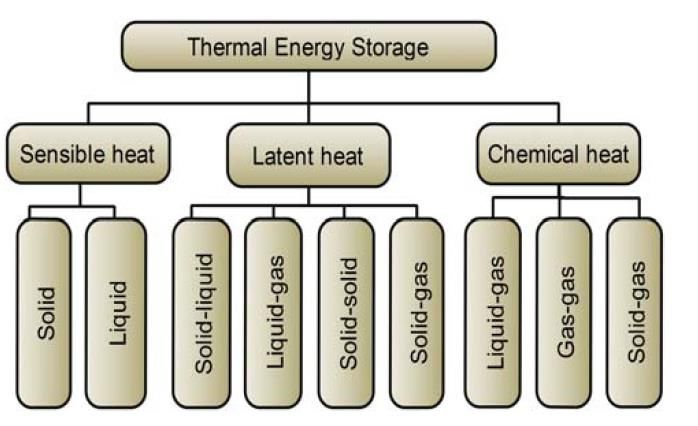
usable due to heat flow and temperature; heat from exhaust gas, heat from cooling water, heat from
lubricating oil cooling water and heat from turbocharger cooler [4].

Even though progress related to WHRS is made within the marine shipping industry, the most
explored area is common land-based industries. This is mainly because the industrial sector is much
larger and therefore stands for a larger portion of the produced waste heat [5]. Also, the shipping
industry has the disadvantage of limited space and a demand for mobility compared to the industrial
sector which makes a waste heat recovery solution more complicated.

1.5.2 Thermal energy storage
Thermal energy storage (TES) is the method of storing heat which allows thermal energy to be used
whenever necessary, it could be hours, days or months away from when it first was generated. The
method of TES is applicable in many fields and is therefore widely used by all kinds of industries.
Some applications of TES are seasonal storage, where summer heat is stored for use in the winter or
when ice is produced during off-peak periods and used for cooling later. It could also be waste heat
generated in industrial processes which is stored and used as district heating [6].

According to several sources, thermal energy storage is usually classified into three categories.
Thermal energy can be stored as sensible heat, latent heat, and thermo-chemical heat or by combining
them (see figure 1) [7]-[8].

 Figure 1. Classification of thermal energy storage [9].

Sensible heat storage (SHS) is the simplest concept and is the method of heating or cooling a solid or a
liquid without changing its phase. The most popular SHS medium is water because it is cheap, easy to
acquire, non-toxic and has high specific heat capacity [8]. Therefore, it is widely used for industrial

 11
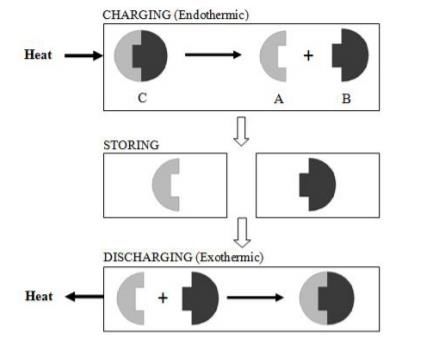
applications. Latent heat storage (LHS), also known as phase change storage, releases or absorbs
energy when the material change phase. By melting and solidifying the material at the phase change
temperature, a phase change material (PCM) can store and release energy [9]. Compared to sensible
heat storage, LHS has higher energy density and the ability to absorb and release heat at almost the
exact same temperature [8]. Chemical heat storage (CHS) uses thermo-chemical materials to store and
release energy in a reversible endothermal/exothermal reaction. When heat is applied to the material in
a charging process, the material separates into two parts which can be stored separately until the
discharging process is desired. The greatest advantage of CHS is high thermal efficiency due to small
thermal losses during the storage period [10].

 12
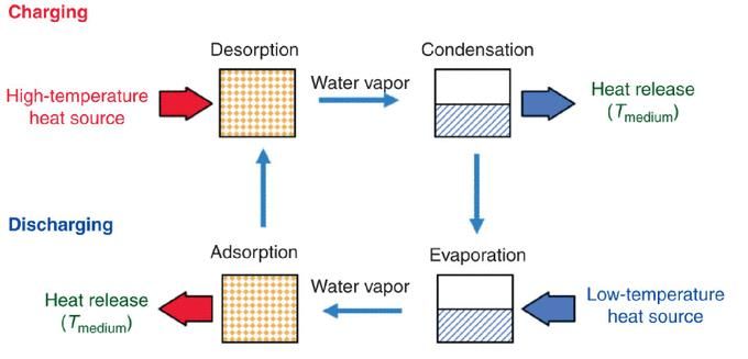
2 THEORY

 2.1 Thermal energy storage
2.1.1 Thermo chemical heat storage in salt
It has been known for a long time that it is possible to store thermal energy in salt. The main principle
of thermochemical heat storage is based on a reaction that can be reversed:

 + ∆ ⇔ + (1)

, where ∆ is the reaction enthalpy.
In this reaction, a thermo chemical material (C) absorbs thermal energy and is converted chemically
into two components (A and B), which can be stored in separate containers. The reverse reaction
occurs when materials A and B are combined, and C is formed again (see figure 2) [11]. The energy
required for the endothermic reaction can be provided by heat from any source. The thermo chemical
material in this case is the salt, ( )2 which splits into and 2 .

 Figure 2. Principle of thermochemical heat storage [12].

Figure 3 shows a principle layout of the salt accumulator system.

 13
Figure 3. The principle layout of the closed adsorption process [13].

During the charging process when heat is applied to the reactor compartment, water vapor detaches
from the salt and is transported to the other container where it condenses. A valve is closed and keeps
the two from each other until the discharge process is required. During the storage period, the salt
oxide can be stored in a sealed space for a an unlimited period of time without because there are no
thermal losses during the storage period [11].

To initiate the discharge process, the water stored in the container is vaporised and the valve is opened
to let the vapor travel back to the salt where the exothermal reaction takes place. The solid adsorbs the
water vapor to form the original product and the adsorption enthalpy is released in the form of heat. As
this is a reversible reaction, the same amount of heat which is released must also applied to initiate the
charging process and decompose the salt into two products [14].

The heat makes the reactor warm and the container where the water was stored gets cold due to an
equalisation of the energy balance [11]. The reaction ends when the all water vapor has moved back to
the reactor and the other container is empty. When the reaction is complete, the initial thermochemical
material is obtained [15].

Because of the nano-coating of the salt, this process can be repeated basically unlimited times without
the quality of the salt degrades [16].

 2.2 Conversion of thermal energy
2.2.1 Rankine cycle
The Rankine cycle was first described in 1859 by Scottish engineer William J.M Rankine. The
Rankine cycle is a thermodynamic cycle which converts thermal energy into mechanical work which

 14
in order can generate electrical power. A simple setup of a Rankine cycle can be seen in figure 4 with
all the primary components. The components include a boiler, expansion device (most likely a
turbine), generator, a condenser and a pump.

 Figure 4. A simple Rankine cycle configuration with main components [17].

The overall process involves a liquid which is heated and condensed repeatedly. There are four
processes happening (see figure 5). At first an isentropic compression takes place where the working
fluid is pumped from low to high pressure (1-2). The working fluid, now at high pressure, is heated
with the external heat source in an isobar process and is evaporated (2-3). The working fluid, which
now is a gas, is superheated (3-4) to reduce condensation as the gas expands through the expansion
device in an isentropic expansion and generates mechanical work (4-5). At this stage there is still some
condensing that occurs which causes corrosion on the turbine blades. The wet vapor runs through the
condenser where it once again becomes a liquid (5-1), this cycle is as mentioned repeated.[18]

1
 Superheated steam is steam at a temperature higher than its vaporization point.

 15
Figure 5. A temperature - entropy diagram of the Rankine cycle, inspired by [18].

The Rankine cycle itself has not a specific working fluid defined but is a description of the general
thermodynamic process. Originally, steam was used as the working fluid and therefore the
conventional Rankine cycle is also usually referred to as the steam cycle, although other working
fluids can be used. Over the years, much research has been done and several new variants of the
conventional Rankine cycle have been developed, an example of such cycle is the organic Rankine
cycle which is described in the next section.

2.2.2 Organic Rankine cycle
The organic Rankine cycle is based on the same principle as the conventional Rankine cycle but uses
an organic compound as the working fluid instead of water/steam, such as ammonia (R-123, R-134a,
R-245fa), pentane (C5H12) or toluene (C7H8) [19]. The overall process of the cycle is the same as
that of the Rankine cycle and the system often consists of the same components [17]. Sometimes a
recuperator can be installed as a liquid preheater between the pump outlet and the expander outlet to
reduce the amount of heat needed to vaporise the fluid in the evaporator [20].

The thermodynamic processes of the cycle remain the same as that of the steam Rankine cycle, the
difference is that the properties of the cycle differentiate. Figure 6 displays the temperature – entropy
diagram for some of the organic fluids compared to the water.

 16
Figure 6. Comparison of entropy for different working fluids. The figure is inspired by [20].

As seen in figure 6, the right slope of the globe is much steeper for the organic working fluids and
consequently the vapor remains superheated at the end of the expansion process. The entropy
difference is smaller for the organic fluids; hence, the vaporisation enthalpy is less. To compensate for
less enthalpy, the mass flow rate of the organic fluid must be higher, leading to increased pump
consumption [21].

2.2.3 Stirling cycle
The Stirling cycle is a thermodynamic cycle similar to the Carnot cycle but with some differences. The
Carnot cycle was first proposed by French physicist Sadi Carnot in 1824 and is a theoretical ideal
thermodynamic cycle which provides the highest amount of usable energy in a thermodynamic
process. It is usually used as a reference when efficiencies of engines are compared because it presents
the highest efficiency possible between two temperature sources.

The cycle itself is built up by four processes [22]; isothermal compression, adiabatic compression,
isothermal expansion and an adiabatic expansion. The thermodynamic processes are described below:
Process 1-2 - Isothermal compression
During the reversible isothermal compression (constant temperature) the working fluid is in contact
with the cold reservoir at temperature 1 . The surrounding does work on the gas causing a loss of heat.
The internal energy remains the same but the entropy decreases (see figure 7-8).

Process 2-3 - Adiabatic compression
In this process, the system is thermally insulated from both heat sources. The piston is pushed further
down as the surrounding do more work on the gas, increasing its internal energy and the temperature
to rise from 2 to 3 (see figure 8).

 17
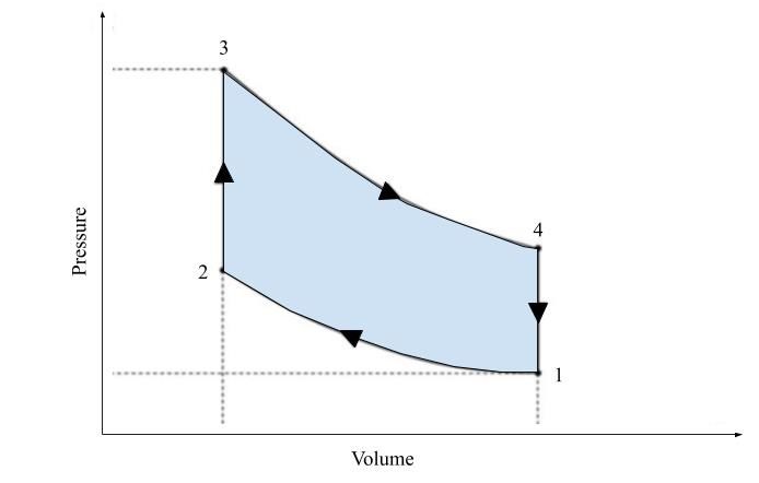
Process 3-4 - Isothermal expansion
During the isothermal gas expansion process the gas is allowed to expand, doing work on the
surroundings by pushing up the piston. The pressure drops from 3 to 4 but the temperature remains
the same because the gas is in contact with the hot reservoir. Heat is absorbed, resulting in increased
entropy (see figure 7).

Process 4-1 - Adiabatic expansion
In this reversible adiabatic gas expansion process, the system is once more thermally insulated. The
gas continues to expand and does work on the surroundings. The loss of internal energy is equal to the
work done by the gas resulting in the temperature decreasing from 4 to 1 . The entropy remains
unchanged (see figure 8).

 Figure 7. Pressure-volume diagram of the Figure 8. Temperature-entropy diagram of
 Carnot processes [23]. the Carnot processes [23].

The efficiency of the Carnot cycle can be derived from the processes described above and can easily
be found from several sources online including the work by Bahman Zohuri [23]. The Carnot
efficiency is given by the expression

 ℎ −
 Ƞ ℎ = (2)
 ℎ

where ℎ is the high temperature source in Kelvin and is the cold temperature source in Kelvin.

Shaw [22] explains the differences between the Carnot cycle and the Stirling cycle. The second (2-3)
and fourth (4-1) processes are different (compare figure 7 and 9). For the Carnot cycle, the second
process is adiabatic compression and the fourth process is adiabatic expansion. To compare those with
the Stirling cycle, where both processes are isochoric meaning the volume is constant. In figure 9 the
pressure-volume graph can be seen for the Stirling cycle.

 18
Figure 9. Pressure-Volume graph for the Stirling cycle [24].

The theoretical efficiency of the Stirling cycle is calculated in the same way as the Carnot efficiency
but it is important to distinguish between a theoretical cycle and how to practically use it. Organ points
out that the Stirling cycle is an implementation, whilst the Carnot cycle is strictly theoretical [25].
Organ [25] lists some of the losses that occurs in a practical implementation and contributes to the
decreasing efficiency:
 • Losses due to heat transfer
 • Pump losses
 • Viscous dissipation (The work done by a fluid on adjacent layers due to shear forces and
 transformed into heat.)
 • Losses due to thermal conductivity
 • Losses due to friction

These losses contribute to a significantly lower efficiency than the Carnot efficiency.

 19
3 METHOD
In this thesis, the method consists of an analysis of the current situation and an investigation of the
interesting areas with the help of a literature review and dialogues with stake holders. The literature
review was used as a tool to identify, select and study concepts of interest built on scientifically
proven facts. The review also aimed to investigate if published literature could provide inspiration for
how previous researchers and students solved similar problems. If similar problems had been
investigated, that information could prove valuable in this study as well. To keep the scientific
relevance, all articles reviewed in this thesis are taken from databases that are assumed to be
scientifically acceptable. The databases used are listed below:
 • Scopus
 • Web of science
 • IEEE explore
 • BTH summon
 • Google Scholar
 • DiVa
 • ScienceDirect

During the review, keywords in both Swedish and English were used to broaden the search as much as
possible, though most of the results were in English. The literature review had to be broad enough in
order to understand the studied literature. A broader review also reduces the probability for any
obvious concepts to be overlooked. However, it was considered more important to choose fewer
concepts to be studied in more detail rather than evaluating as many concepts as possible.

Figure 10 describes the intended method of the literature review, in order to make the method as
efficient as possible the method of approach was planned at the beginning of the project.

 20
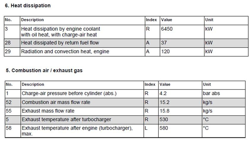
Figure 10. Intended structure of how the literature review was carried out.

 3.1 Dialogue with stake holders
Throughout the entire project, meetings were held as a complement to the literature study to find
information. Meetings with SaltX were held to collect information regarding thermal energy storage in
salt.

It was also considered important to have a continuous discussion with Saab Kockums AB throughout
the project as they could provide an input on certain areas, for example the current conditions on ships
and specific knowledge about certain areas. In addition, contact with the department of Stirling at Saab
Kockums AB was initiated. During the meetings with the Stirling, it was possible to get a basic
understanding for how the engines work and their potential in this study. Some of the information that
needed to be investigated was only possible to find through this communication.

At the initial phase of the project, the plan was to have more meetings and study visits but parts of
them got cancelled due to the effects of COVID-19.

 3.2 Current system characteristics
The analysis of the current system characteristics will not produce a result or answer any of the thesis
questions. It was performed to clarify the impact a waste heat recovery system can make on a vessels
total energy consumption. The current conditions will be used as a reference to the result.

 21
As described in the introduction, the aim of this project is to utilise fuel consumption by recovering
waste heat energy. This thesis is a feasibility study that explores the potential and possibilities for
waste heat recovery for Saab Kockums AB diesel powered platforms. During the analysis, it became
clear that the work could be applied to other platforms as well, other than the ones in in this study.
There are platforms which have different systems and engines etc, therefore, depending on which
platform is used there will be different types of waste heat available. For example, there are ships that
are propelled with gas turbines and the exhaust gas could be another possible waste heat resource.
These vessels have the possibility to utilise thermal sources of approximately 600 °C. These platforms
were not considered in this study. In this study three types of external thermal energy sources are
available, two high temperature sources and low temperature source, they are listed below.
 1. A hot temperature source of approximately 85°C where the energy is carried in water.
 (Cooling water from diesel engines)
 2. A hot source of approximately 250-530 °C where the energy is carried in air. (Exhaust gas
 from diesel engines)
 3. A cold source of approximately 2-15 °C (Sea water)

The second part of the study was to analyse thermal energy storage possibilities. The ability to store
thermal energy and use it when needed is a highly desired feature on a ship where storage and energy
access are limited. At the moment, lead acid batteries are used with a storage capacity of 30-70
kWh/ton [26],[27],[28] to store and supply electrical energy. Other types of batteries with higher
energy density have been investigated by Saab Kockums AB as alternatives. For example, lithium-ion
possesses higher energy density at approximately 120-250 kWh/ton. The substantial disadvantage is
that they are toxic to both crew the environment in if they are overheated or overcharged [28]. The
method of storing thermal energy instead of electrical energy could be a possible solution for
increased power supply but remain harmless to the environment.

The conditions on the vessel are varying depending on the operational profile, each ship operates
differently depending on the vessel type and what kind of mission is to be executed. The operating
profile consists of a set of operational modes which decides how the engines are loaded. Each ship
usually has its own different operational modes, these must be considered when the waste heat
recovery system is designed. The operational modes of a vessel are important because the loading of
the engines impact the available temperatures and energy content of the thermal sources. In the next
section the available heat is calculated for a specific ship and operating profile.

 22
3.2.1 Calculation of available thermal energy
An example of a marine platform is presented in figure 11. The calculations will estimate the amount
of thermal energy which is wasted. Later, this example will be used as a reference for the result. The
platform in this example has two powertrains consisting of one marine diesel engine (ME) as the
primary propulsion, one electric motor (EM) for secondary propulsion (EM) and two diesel generators
(DG) of 2 MW for power generation each. The engine can be used separately or in combination with
each other. There is a constant need for power whether electric motors are used or not. To meet the
constant demand for power, approximately 3 MW, at least two diesel generators are always active to
supply enough power. When the electric motors are used for propulsion, all four diesel generators are
required because of the increased power demand. Each electric motor can deliver 2 MW of electrical
power if requested.

 Figure 11. Example platform with propulsion and power generation.

Table 2 shows a daily operational profile with four sets of operational modes. The operating time for
each mode is taken from a real profile and the temperatures are data from actual engines (see
Appendix A).

 23
Table 2. Example of operating modes.
Mode Engine Operating time, ME DG EM Temp, exhaust Temp, cooling
 Load [%] daily [h] Active Active Active gases [°C] water [°C]
 1 95 3.6 2 2 0 530 85
 2 55 4.8 2 2 0 370 85
 3 30 7.6 2 2 0 250 85
 4 20 8 0 4 2 - -

The wasted thermal energy will be calculated for each mode and added together to obtain the total
amount of available energy. How the energy is calculated will be demonstrated for the first mode only
because the remaining modes follow the same procedure but with different data. All data regarding the
engine and fuel for mode 1 required for the calculations can be seen in table 3.

 Table 3. Fuel and engine data for calculation of thermal energy.
 Parameters Unit Value
 Nominal power for ME MW 10
 Specific fuel consumption at nominal power for ME ( ) g/kWh 198
 Heat value for fuel ( ) MJ/kg 42.80
 Heat to coolant at nominal power for ME kW 6450

The first step is to find out the amount of power that goes to exhaust gases by calculating the total
fuel power for maximum load and subtract the power that goes to coolant using equation 3.

 × × 42.8×198×10 000
 = = = 23 540 = 23.54 (3)
 3600 3600

According to the engine manufacturer, 6450 kW (27.4%) of the fuel power goes to cooling water
and because 10 000 kW is the mechanical output the remaining 7090 kW (30.12%) goes to
exhaust gases.

With the ratio of power to exhaust gases known, the available thermal energy for mode 1 can be
calculated. The total fuel power at 95% load is calculated with data from table 2 and 3 in equation
4.

 ℎ × × 42.8×198×9500
 = 3600
 = 3600
 = 22 363 = 22.363 (4)

 24
The calculated proportions for where the heat goes still apply, out of the total fuel power for mode
1, 27.4% (6127 kW) of heat goes to cooling water and 30.12% (6735 kW) of heat to exhaust
gases. Because there are two powertrains, the numbers are doubled to obtain the total amount of
heat power lost. The generated thermal energy by mode 1 for one day is then calculated by
multiplying the available heat power with the operating time for that mode (see table 2):

 = 6127 × 2 × 3.6 = 44 114 = 44.11 ℎ (5)
 ℎ = 6735 × 2 × 3.6 = 48 492 = 48.50 ℎ (6)

Table 4 below shows a summary of the total amount of available thermal energy for all modes,
calculated in the same way as for mode 1.

 Table 4. Summary of the daily available thermal energy.
 ME load [%] Energy cooling water [MWh] Energy exhaust gas [MWh] Sum [MWh]
 95 44.11 48.50 92.61
 55 33.71 37.06 70.77
 30 14.56 16.00 30.56
 Sum [MWh] 92.38 101.55 193.94

3.2.2 Important properties of a waste heat recovery system
There are many areas on a ship where an extra stock of heat could make a difference. The thermal
energy could be converted into mechanical work and then integrated into the propulsion lines as
support, it could be used for power generation or the heat could be distributed and used as district
heating.

A ship can be compared to a small city, everything a city requires a ship also needs. These
requirements could be everything from water supply, heating and cooling to electricity. Thus, there are
several other ways in which the heat could have been used. After discussions with Saab Kockums AB,
it became clear that the need for electricity is what is most important. Electricity on ships is used
everywhere for example; all kinds of electronics, ventilation, navigation, weapon systems, everyday
use for the crew. An interesting aspect is to investigate if a WHRS could recover enough energy to
supply the ships daily demand for electrical energy in order to power the electric motors.

 25
After the analysis of the current situation, a list of the aspects that were considered most important for
a future energy conversion concept was compiled:
 • Thermal efficiency
 • Generated power of the concept
 • Harmless to the crew and environment
 • Reliability
 • Working fluids
The mentioned parameters must be considered but in discussion with Saab Kockums AB, it was
determined that the thermal efficiency of the concept is the deciding variable for which cycle is the
most suitable in this study.

After analysing the current situation, the following aspects were considered most important for
thermal energy storage:
 • Efficiencies
 • Energy density
 • Storage period
 • Charge and discharge duration
 • Charge and discharge cycles
 • Generated power
 • Toxicity
 • Reliability
 • Heating sources
 • Pressures

 3.3 Thermal energy storage
3.3.1 Identification thermal energy storage methods
The storage solution that was investigated in this thesis was the salt provided from SaltX Technology,
but to put it into perspective, a wider search was performed to identify alternative solutions. In section
1.5.2, thermal energy storage was classified into three groups; sensible, latent and thermo chemical
heat storage.

3.3.2 Selection of thermal energy storage methods
When the sensible heat storage (SHS) methods were researched, it failed to fulfil most of the
requirements of the function analysis and were therefore discarded. SHS has in general low energy
density, low thermal conductivity and requirement for large storage space [10], [9]. SHS was therefore
not relevant enough to be considered for energy storage on ships.

 26
You can also read