BIS VISTA Monitoring - SERVICE INFORMATION MANUAL
←
→
Page content transcription
If your browser does not render page correctly, please read the page content below
BIS VISTA Monitoring
System
SERVICE INFORMATION MANUAL
Aspect Medical Systems, Inc.
Bispectral Index (BIS) Monitoring System
Rx only
EC REP
Aspect Medical Systems, Inc. Aspect Medical Systems International B.V.
One Upland Road 3454 PV De Meern
Norwood, MA 02062 USA Rijnzathe 7d2 0123
(Tel) 617-559-7000 The Netherlands
(Tel) 888-BIS INDE(X) (U.S. only) Tel: +31.30.662.9140
(Fax) 617-559-7400 Fax: +31.30.662.9150
bis_info@aspectms.com amsint@aspectms.com
www.aspectmedical.com
075-0015 1.00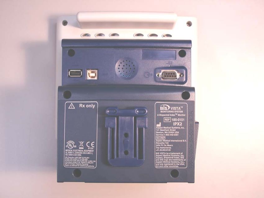
BIS VISTA Monitoring
System
SERVICE INFORMATION MANUAL
Aspect Medical Systems, Inc.
Bispectral Index (BIS) Monitoring System
Copyright, 2006, Aspect Medical Systems. All rights reserved. Copying or other
reproduction of this document is prohibited without prior written consent of Aspect
Medical Systems.
BIS VISTA, BISx and the BISx logo are trademarks of Aspect Medical Systems, Inc.
Aspect, Bispectral Index, BIS, the BIS logo, and Zipprep are trademarks of Aspect Medical
Systems, Inc. and are registered in the USA., EU and other countries.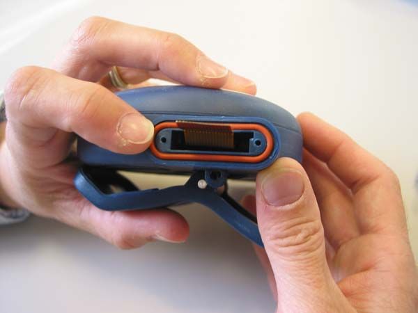
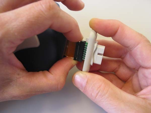
TABLE OF CONTENTS

ABOUT THIS MANUAL ............................................................................................................. VIII

1        SAFETY PRECAUTIONS.................................................................................................... 1-1
    1.1             WARNINGS ................................................................................................................................................. 1-1
    1.2             CAUTIONS ................................................................................................................................................... 1-4
    1.3             KEY TO SYMBOLS ........................................................................................................................................ 1-6
2        BIS VISTA MONITORING SYSTEM OVERVIEW ........................................................... 2-1
    2.1             INTRODUCING THE BIS VISTA MONITORING SYSTEM .......................................................................... 2-1
    2.2             PRINCIPAL COMPONENTS .......................................................................................................................... 2-2
       2.2.1           The BIS VISTA Monitor........................................................................................................................................ 2-2
       2.2.2           The BISx and Patient Interface Cable (PIC) ................................................................................................... 2-4
    2.3             INSTRUMENT IDENTIFICATION .................................................................................................................. 2-4
    2.4             PROPRIETARY INFORMATION AND DEVICES ............................................................................................ 2-5
3        PRINCIPLES OF OPERATION .......................................................................................... 3-1
    3.1      HOW THE BIS VISTA MONITORING SYSTEM WORKS ........................................................................... 3-1
    3.2      SYSTEM ARCHITECTURE ............................................................................................................................. 3-1
       3.2.1    The BISx................................................................................................................................................................... 3-3
       3.2.2    The BIS VISTA Monitor........................................................................................................................................ 3-5
    3.3      SYSTEM FEATURES ....................................................................................................................................... 3-6
       3.3.1    System Self Checks ............................................................................................................................................... 3-6
       3.3.2    Diagnostic Codes ................................................................................................................................................... 3-7
       3.3.3    Monitor Data Memory......................................................................................................................................... 3-7
       3.3.4    BISx Data Memory ............................................................................................................................................... 3-8
       3.3.5    Saved Settings......................................................................................................................................................... 3-8
       3.3.6    Battery Operation.................................................................................................................................................. 3-8
       3.3.7    Data Transfer and Software Updates ............................................................................................................. 3-9
4        PREPARATION FOR USE AND INSTALLATION ......................................................... 4-1
    4.1      ENVIRONMENT ............................................................................................................................................ 4-1
       4.1.1    Shipping and Storage Environment .................................................................................................................. 4-1
       4.1.2    Operating Environment........................................................................................................................................ 4-1
       4.1.3    Power Requirements and System Grounding................................................................................................. 4-2
       4.1.4    Site Preparation: Mounting the Monitor ......................................................................................................... 4-2
    4.2      INSTRUMENT CONNECTIONS.................................................................................................................... 4-4
       4.2.1    Connecting the BISx.............................................................................................................................................. 4-4
       4.2.2    Power Cord Connections...................................................................................................................................... 4-4
    4.3      INSTALLATION AND VERIFICATION PROCEDURE .................................................................................... 4-4
5        CARE AND CLEANING...................................................................................................... 5-1
    5.1      CARE AND CLEANING................................................................................................................................ 5-1
       5.1.1   Cleaning the Monitor and BISx.......................................................................................................................... 5-1
       5.1.2   Disinfecting the Monitor and BISx .................................................................................................................... 5-1
       5.1.3   Cleaning the Monitor Display............................................................................................................................. 5-2
6        PREVENTIVE MAINTENANCE ......................................................................................... 6-1
    6.1      PHYSICAL INTEGRITY INSPECTION ............................................................................................................ 6-1
    6.2      SYSTEM CHECKOUT ................................................................................................................................... 6-1
       6.2.1    Monitor Checkout Procedure.............................................................................................................................. 6-2

                                                                                             v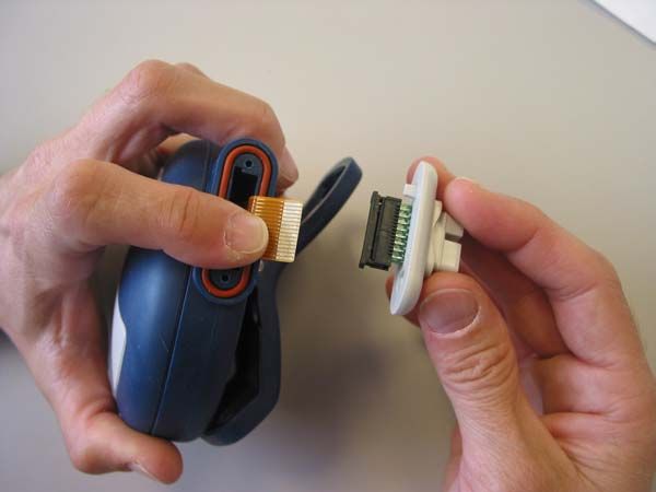
6.2.2   BISx Checkout Procedure .................................................................................................................................... 6-3
        6.2.3   Patient Interface Cable (PIC) Checkout Procedure....................................................................................... 6-4
     6.3      CHECKING THE BATTERY .......................................................................................................................... 6-5
     6.4      CHECKING LEAKAGE CURRENT ................................................................................................................ 6-6
7         DIAGNOSTICS AND TROUBLESHOOTING ................................................................. 7-1
     7.1            GENERAL TROUBLESHOOTING ................................................................................................................. 7-1
     7.2            BIS VISTA MONITORING SYSTEM TROUBLESHOOTING PROCEDURE................................................... 7-2
     7.3            BIS VISTA SYSTEM MESSAGES AND CORRECTIVE ACTIONS .................................................................. 7-4
8         SERVICING THE BIS VISTA SYSTEM.............................................................................. 8-1
     8.1            REPLACING THE PIC................................................................................................................................... 8-1
     8.2            REPLACING THE BISX ................................................................................................................................. 8-1
     8.3            REPLACING THE MONITOR ........................................................................................................................ 8-2
     8.4            REPLACING THE BATTERY .......................................................................................................................... 8-3
     8.5            REPLACING THE POWER SUPPLY ............................................................................................................... 8-4
     8.6            REPLACING THE CLAMP SHOE ................................................................................................................... 8-5
     8.7            REPLACING THE MONITOR INTERFACE CABLE ........................................................................................ 8-6
        8.7.1          Parts and Tools Required .................................................................................................................................... 8-6
        8.7.2          Procedure:................................................................................................................................................................ 8-6
     8.8            REPLACING THE BISX BULKHEAD CONNECTOR ..................................................................................... 8-9
        8.8.1          Parts and Tools Required .................................................................................................................................... 8-9
        8.8.2          Procedure:..............................................................................................................................................................8-10
     8.9            CALIBRATING THE TOUCH SCREEN ........................................................................................................ 8-13
     8.10           USING THE RESET BUTTON ..................................................................................................................... 8-13
     8.11           BISX CHECKOUT AND SAFETY TESTS..................................................................................................... 8-13
     8.12           WHAT TO DO WITH A COMPONENT THAT REQUIRES SERVICE .......................................................... 8-14
     8.13           REPACKAGING FOR SHIPPING AND STORAGE........................................................................................ 8-14
9         SPECIFICATIONS AND WARRANTY ............................................................................. 9-1
     9.1      GENERAL SPECIFICATIONS ......................................................................................................................... 9-1
     9.2      ELECTROMAGNETIC COMPATIBILITY SPECIFICATIONS ............................................................................ 9-5
        9.2.1    Accessories............................................................................................................................................................... 9-5
        9.2.2    IEC 60601-1-2:2001 Electromagnetic Compatibility Guidance............................................................... 9-6
     9.3      WARRANTY .............................................................................................................................................. 9-11
10        APPENDIX I........................................................................................................................ 10-1
     10.1           ACCESSORIES AND SPARE PARTS LIST ..................................................................................................... 10-1
     10.2           SENSOR SIMULATOR: P/N: 186-0137 ........................................................................................... 10-2
     10.3           TEST SENSOR............................................................................................................................................. 10-3
     10.4           SAFETY TESTER CONNECTION WITH PIC.............................................................................................. 10-5
11        APPENDIX II ...................................................................................................................... 11-7
     11.1           DATA FLOW DIAGRAM ............................................................................................................................ 11-7
     11.2           BLOCK DIAGRAM ..................................................................................................................................... 11-8

                                                                                               vi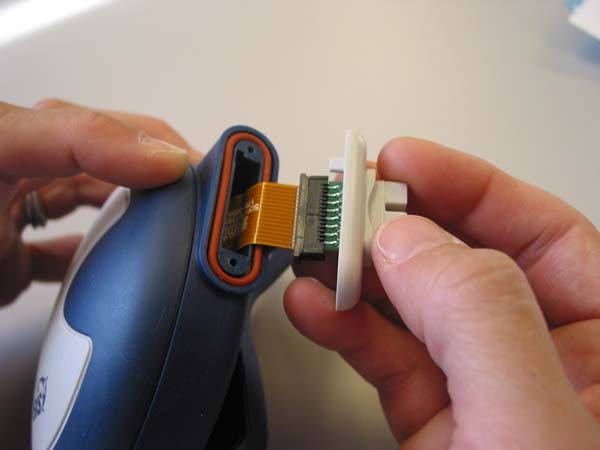
TABLE OF FIGURES

Figure 1 - Symbol Key (page 1 of 3)................................................................................ 1-6
Figure 2- The BIS VISTA Monitoring System.................................................................. 2-2
Figure 3 - Rear Panel ...................................................................................................... 2-3
Figure 4 - The BISx and PIC ........................................................................................... 2-4
Figure 5 - The BIS VISTA System Block Diagram .......................................................... 3-2
Figure 6 - The BIS VISTA Data Flow Diagram .............................................................. 3-3
Figure 7 - Pole Clamp ..................................................................................................... 4-3
Figure 8 - Schematic of Sensor Simulator Circuit........................................................ 10-2
Figure 9 - Sensor Simulator.......................................................................................... 10-3
Figure 10 - BIS Sensor................................................................................................... 10-3
Figure 11 - Connecting electrodes #2 and #4. .............................................................. 10-4
Figure 12 - Connecting electrode #3 with #4, and #1 with #2. .................................... 10-4
Figure 13 - Safety Tester Contact Points....................................................................... 10-5

                                                              vii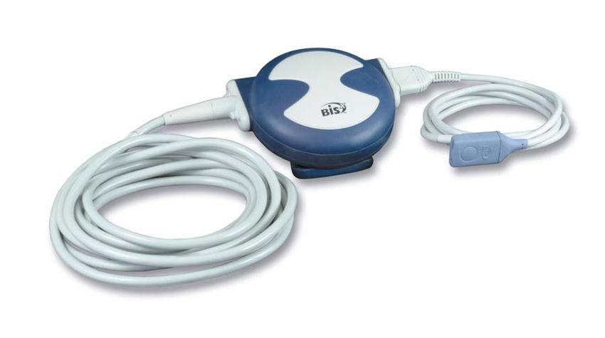
ABOUT THIS MANUAL
_______________________________________________________________________
ABOUT THIS MANUAL
This manual contains information necessary for the customer to install, maintain, service,
identify and prepare for use Aspect Medical Systems’ BIS VISTA Monitoring System. Also
included are directions to diagnose, troubleshoot, and repair the system. A spare parts and
accessories list and system specifications are included.
This manual is intended to be used in combination with the BIS VISTA Monitoring System
Operating Manual.
The BIS VISTA Monitoring System is designed and manufactured using state-of-the-art
components and manufacturing processes. Field repair or customer repairs are therefore
limited by design to replacement of major component assemblies such as the Patient
Interface Cable (PIC), BISx™, or the power supply and battery of the BIS VISTA monitor.
This manual, in conjunction with the BIS VISTA Monitoring System Operating Manual,
contains the maintenance and diagnostic troubleshooting information necessary for
customer qualified technical personnel to test and replace those parts of the equipment that
are replaceable by the customer. Aspect does not authorize nor provide information to
service or repair the internal components of the BIS VISTA monitor, with the exception of
the power supply and battery.
Before attempting to set up or service the BIS VISTA Monitoring System, please familiarize
yourself with the safety information provided in Section 1 of this manual.
viii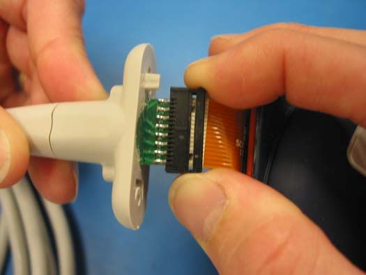
SECTION 1                                       SAFETY PRECAUTIONS
________________________________________________________________________

SECTION 1
1 SAFETY PRECAUTIONS
INTRODUCTION:
                                      Caution:
       Carefully read the BIS VISTA Monitoring System Operating Manual
       entirely before using the monitor in a clinical setting.

WARNINGS, CAUTIONS, AND NOTES

The terms warning, caution, and note have specific meanings in this manual.

   •   A WARNING advises against certain actions or situations that could result in
       personal injury or death.
   •   A CAUTION advises against actions or situations that could damage equipment,
       produce inaccurate data, or invalidate a procedure, although personal injury is
       unlikely.
   •   A NOTE provides useful information regarding a function or procedure.

KEY TO SYMBOLS

A key to the symbols used on the BIS VISTA Monitoring System appears at the end of this
section.

1.1       Warnings
THE USE OF ACCESSORY EQUIPMENT NOT COMPLYING WITH THE
EQUIVALENT SAFETY REQUIREMENTS OF THIS EQUIPMENT MAY
LEAD TO A REDUCED LEVEL OF SAFETY OF THE RESULTING SYSTEM.
CONSIDERATION RELATING TO THE CHOICE SHALL INCLUDE:
  • USE OF THE ACCESSORY IN THE PATIENT VICINITY
  • EVIDENCE THAT THE SAFETY CERTIFICATION OF THE
     ACCESSORY HAS BEEN PERFORMED IN ACCORDANCE TO THE
     APPROPRIATE IEC 60601-1 AND/OR IEC 60601-2-26 HARMONIZED
     NATIONAL STANDARD.

WHEN CONNECTING EXTERNAL EQUIPMENT (e.g., DATA CAPTURE
COMPUTER), THE SYSTEM LEAKAGE CURRENT MUST BE CHECKED
AND MUST BE LESS THAN THE IEC 60601-1 LIMIT.

EXPLOSION HAZARD: DO NOT USE THE BIS VISTA SYSTEM IN A
FLAMMABLE ATMOSPHERE OR WHERE CONCENTRATIONS OF
FLAMMABLE ANESTHETICS MAY OCCUR.

MONITOR IS NOT DESIGNED FOR USE IN MRI ENVIRONMENT.

                                            1-1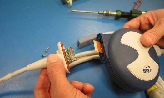
SECTION 1                                       SAFETY PRECAUTIONS
________________________________________________________________________

FOR PROPER GROUNDING, THE POWER RECEPTACLE MUST BE A
THREE-WIRE GROUNDED OUTLET. A HOSPITAL GRADE OUTLET IS
REQUIRED. NEVER ADAPT THE THREE-PRONG PLUG FROM THE
MONITOR TO FIT A TWO-SLOT OUTLET. IF THE OUTLET HAS ONLY
TWO SLOTS, MAKE SURE THAT IT IS REPLACED WITH A THREE-SLOT
GROUNDED OUTLET BEFORE ATTEMPTING TO OPERATE THE
MONITOR.

IF THE INTEGRITY OF THE EXTERNAL PROTECTIVE EARTH GROUND
IS IN DOUBT, THE BIS VISTA SYSTEM SHALL BE OPERATED FROM ITS
INTERNAL BATTERY POWER SOURCE ONLY.

FOR BIS VISTA SYSTEMS USED OUTSIDE OF NORTH AMERICA: A
HARMONIZED LINE CORD WITH CONDUCTORS HAVING A CROSS
SECTIONAL AREA GREATER THAN 0.75 mm2 MUST BE USED.

BE SURE THE MONITOR IS MOUNTED SECURELY IN PLACE TO AVOID
PERSONAL OR PATIENT INJURY.

UNIVERSAL PRECAUTIONS SHALL BE OBSERVED TO PREVENT
CONTACT WITH BLOOD OR OTHER POTENTIALLY INFECTIOUS
MATERIALS. PLACE CONTAMINATED MATERIALS IN REGULATED
WASTE CONTAINER.

WHENEVER AN EVENT SUCH AS SPILLAGE OF BLOOD OR SOLUTIONS
OCCURS, RE-TEST BEFORE FURTHER USE.

DO NOT MIX DISINFECTING SOLUTIONS (e.g., BLEACH AND AMMONIA),
AS HAZARDOUS GASES MAY RESULT.

ELECTRICAL SHOCK HAZARD: THE MANUFACTURER'S INSPECTION OF
THIS APPARATUS VERIFIED THAT THE GROUND LEAKAGE CURRENT
AND THE PATIENT SAFETY CURRENT WERE LESS THAN THE
SPECIFIED LIMITS ESTABLISHED BY THE APPLICABLE SAFETY
STANDARDS. AS A MATTER OF SAFE PRACTICE, THE INSTITUTION
SHOULD CONDUCT PERIODIC TESTS TO VERIFY THESE CURRENTS.

ELECTRICAL SHOCK HAZARD: DO NOT REMOVE MONITOR COVERS
DURING OPERATION OR WHILE POWER IS CONNECTED TO MONITOR.

GROUND WIRE LEAKAGE CURRENT MUST BE CHECKED WHENEVER
INSTRUMENT CASE IS OPENED BY A QUALIFIED BIOMEDICAL
ENGINEERING TECHNICIAN.

POWER SUPPLY IS INTERNALLY FUSED. REPLACE POWER SUPPLY ONLY
WITH ASPECT MEDICAL SYSTEMS BIS VISTA POWER SUPPLY.

                                  1-2
SECTION 1 SAFETY PRECAUTIONS
________________________________________________________________________
ENSURE THAT THE BISx DOES NOT COME INTO PROLONGED
CONTACT WITH PATIENT’S SKIN, AS IT MAY GENERATE HEAT AND
CAUSE DISCOMFORT.
THE CONDUCTIVE PARTS OF ELECTRODES OR SENSOR AND
CONNECTORS, INCLUDING THE NEUTRAL ELECTRODE, SHOULD NOT
CONTACT OTHER CONDUCTIVE PARTS, INCLUDING EARTH.
TO REDUCE THE HAZARD OF BURNS IN THE HIGH-FREQUENCY
SURGICAL NEUTRAL ELECTRODE CONNECTION, THE SENSOR OR
ELECTRODES SHOULD NOT BE LOCATED BETWEEN THE SURGICAL
SITE AND THE ELECTRO-SURGICAL UNIT RETURN ELECTRODE.
THE SENSOR MUST NOT BE LOCATED BETWEEN DEFIBRILLATOR
PADS WHEN A DEFIBRILLATOR IS USED ON A PATIENT CONNECTED
TO THE BIS VISTA SYSTEM.
TO MINIMIZE THE RISK OF PATIENT STRANGULATION, THE PATIENT
INTERFACE CABLE (PIC) MUST BE CAREFULLY PLACED AND SECURED.
SHOCK HAZARD: DO NOT ATTEMPT TO DISCONNECT THE POWER
CORD WITH WET HANDS. MAKE CERTAIN THAT YOUR HANDS ARE
CLEAN AND DRY BEFORE TOUCHING THE POWER CORD.
CONSIDERATIONS WHEN USING ELECTRO CONVULSIVE THERAPY
(ECT) EQUIPMENT DURING BIS MONITORING:
SEPARATE ECT ELECTRODES FROM THE BIS SENSOR AS MUCH AS
POSSIBLE TO MINIMIZE THE EFFECT OF INTERFERENCE.
CERTAIN ECT EQUIPMENT MAY INTERFERE WITH THE PROPER
FUNCTION OF THE BIS MONITORING SYSTEM. CHECK FOR
COMPATIBILITY OF EQUIPMENT DURING PATIENT SETUP.
1-3SECTION 1 SAFETY PRECAUTIONS
________________________________________________________________________
1.2 Cautions
Read this entire manual carefully before using the monitor in a clinical setting.
To turn off all A/C power, disconnect power cord from A/C outlet. Battery can be
removed to shut down unit completely.
Continuous impedance checking may need to be disabled if the 1 nanoampere 128
Hz impedance check signal interferes with other equipment (e.g., evoked potential
monitors).
Do not autoclave the BISx or Monitor. Autoclaving will seriously damage both
components.
Avoid liquid ingress to the Patient Interface Cable. Contact of fluids with the PIC
sensor connector can interfere with PIC performance.
Check the battery periodically by operating a BIS VISTA monitor that has been
disconnected from the wall socket and that has been charged to full capacity (at least
6 hours of charge time). After long periods of storage (e.g., more than 1 month) it
may be necessary to cycle (charge, then discharge) the battery a few times to get full
charge capacity. If the BIS VISTA monitor fails to operate reliably from the battery
for approximately 45 minutes, battery replacement is required.
The BIS VISTA monitor contains an internal lithium ion battery. The battery must
be removed by a qualified service technician and disposed of or recycled in
accordance with the national laws of the country. Contact Aspect Medical Systems,
Inc. or the local distributor for a replacement battery: Aspect part number 186-0208.
All repairs to the BIS VISTA Monitoring System should be made only by a qualified
Biomedical Engineering Technician or other authorized personnel.
Use only the parts and tools specified. Use of any others may damage the
instrument.
Using accessories other than those specified may result in increased electromagnetic
emissions or decreased electromagnetic immunity of the BIS VISTA Monitoring
System.
The BIS VISTA Monitor should not be used adjacent to or stacked with other
equipment. If adjacent or stacked use is necessary, the BIS VISTA monitor should
be observed to verify normal operation in the configuration in which it will be used.
Do not block ventilation inlet holes on the underside of monitor.
1-4SECTION 1 SAFETY PRECAUTIONS
________________________________________________________________________
Do not open the BISx for any reason. The seal to prevent liquids from entering the
BISx may be damaged if opened. Service or repairs must be performed only by
qualified biomedical technicians.
The BIS VISTA system has been designed to operate with a BIS Sensor. The sensor
is a silver/silver chloride electrode array that utilizes Aspect's patented Zipprep
technology and uses a proprietary connector. Use of other electrodes is not
recommended.
Do not disconnect the BISx during the software upgrade.
The BIS VISTA system complies with the electromagnetic compatibility
requirements of EN60601-1-2. Operation of this device may affect or be affected by
other equipment in the vicinity due to electromagnetic interference (EMI). If this
occurs:
• Increase separation between devices
• Re-orient device cabling
• Plug devices into separate outlet circuit branches
Refer to Section 9.2 “Electromagnetic Compatibility Specifications.”
When connecting or disconnecting BISx, take care not to touch the exposed contacts
of either connector. Damage due to electrostatic discharge may result.
All work involving opening the instrument case must be performed in a static-safe
environment to prevent damage to electronic components and assemblies. This
environment includes the operator, work area and tools, and any other test or storage
items that might touch the monitor or BISx assemblies.
Important:
The BIS VISTA systems comply with the European Medical Device Directive
(MDD) and applicable regulatory requirements of the country distributed to and
carry the CEXXXX Marking. Declarations of Conformity provided upon request
where appropriate.
1-5SECTION 1 SAFETY PRECAUTIONS
________________________________________________________________________
1.3 Key to Symbols
Manufacturer
EC REP Authorized Representative in the European Community
Conformité Européenne (CE) Marking of Conformity to European
Medical Device Directive. CEXXXX represents the Notified Body
number
Classified by Underwriters Laboratories Inc. with respect to electric
shock, fire and mechanical hazards only, in accordance with
UL 60601-1 and IEC60601-2-26
Recognized under the Component Recognition Program of
Underwriters Laboratories Inc.
Latex-free product
Type BF Equipment
Type BF Equipment Defibrillator-proof
Crossed out wheelie bin indicates separate treatment from general
waste at end of life
Attention, Consult Accompanying Documents
Attention, Data I/O, RS-232 Serial Port, Consult Accompanying
Documents
Figure 1 - Symbol Key (page 1 of 3)
1-6SECTION 1 SAFETY PRECAUTIONS
________________________________________________________________________
Attention, USB-A, Host. Consult Accompanying Documents
USB-A
Attention, USB-B function. Consult Accompanying Documents
USB-B
Caution: Hot Surface
Alternating Current
D/C Current
Battery Location
Reset Button
Packaging Labelling:
Storage Temperature Limits, Fragile, Do Not Get Wet, and This
Side Up
Monitor Power ON
Monitor Power OFF or Standby Mode
Figure 1 - Symbol Key (page 2 of 3)
1-7SECTION 1 SAFETY PRECAUTIONS
________________________________________________________________________
Operating on Battery
No Battery is Installed in Monitor
Ringing Bell Icon - Alarm Sounding
Green Bell Icon - Alarms Active
Yellow Bell with Dotted Line ‘X’ - Alarms Paused
Red Bell with ‘X’ - Alarms Silenced
A green box denotes ON or active condition.
A red box with an ‘X’ denotes OFF or cancel.
Figure 1 - Symbol Key (page 3 of 3)
1-8SECTION 2 BIS VISTA MONITORING SYSTEM OVERVIEW
_______________________________________________________________________
SECTION 2
2 BIS VISTA MONITORING SYSTEM
OVERVIEW
2.1 Introducing the BIS VISTA Monitoring
System
The BIS VISTA Monitoring System is intended for use under the direct supervision of a
licensed healthcare practitioner or by personnel trained in its proper use. The BIS VISTA
Monitor is intended for use on adult and pediatric patients within a hospital or medical
facility providing patient care to monitor the state of the brain by data acquisition of EEG
signals.
The BIS may be used as an aid in monitoring the effects of certain anesthetic agents. Use of
BIS monitoring to help guide anesthetic administration may be associated with the reduction
of the incidence of awareness with recall in adults during general anesthesia and sedation.
The BIS VISTA Monitoring System processes raw EEG signals to produce a single number,
called the Bispectral Index, or BIS, which correlates to the patient’s level of hypnosis. It
operates from an AC power source of 100V to 240V, 50/60Hz, and provides approximately
45 minutes of automatic back-up battery power.
The monitor is menu-driven with on-screen touch keys. A detailed description of how the
BIS VISTA Monitoring System works is included in the BIS VISTA Operating Manual.
Please refer to the BIS VISTA Operating Manual for additional information.
2-1SECTION 2 BIS VISTA MONITORING SYSTEM OVERVIEW
_______________________________________________________________________
BIS VISTA monitor
BIS sensor
Patient Interface
Monitor Cable (PIC)
Interface
Cable
BISx
Figure 2- The BIS VISTA Monitoring System
2.2 Principal Components
The system is composed of a monitor, a BISx, a Patient Interface Cable (PIC), and BIS
sensor.
2.2.1 The BIS VISTA Monitor
The front panel of the BIS VISTA monitor contains the Touch Screen, BISx port and the
ON/Standby button. See Figure 2.
Touch Screen
The BIS VISTA monitor is designed so that all controls (with the exception of the
ON/Standby button) are accessible by touching a designated area on the monitor screen.
This area is called a touch key. The touch keys are designed to function even when the user
is wearing examination gloves.
2-2SECTION 2 BIS VISTA MONITORING SYSTEM OVERVIEW
_______________________________________________________________________
ON/Standby button
The ON/Standby button is located in the lower right corner of the monitor and is used to
put the monitor in ON or in Standby mode. When the small LED light to the right of the
ON/Standby button is green, the unit is running and providing power to the BISx. When it
is yellow, the battery is charging and the system is in Standby mode. When it is not lit, no
A/C power is available to the unit; pressing the ON/Standby button will start up the
monitor using the battery.
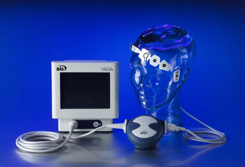
USB Port
(Type A)
Reset Button
USB Port Serial Port
(Type B)
Power Cord
Battery/Power Receptacle
Supply Cover
Clamp Shoe
Figure 3 - Rear Panel
Rear Panel
The rear panel components are pictured in Figure 3. They include: two USB ports (Type A
and B), the clamp shoe, an RS-232 port, the Reset button, the Battery/Power Supply cover,
and the power cord receptacle.
The clamp shoe allows the monitor to slide into the pole clamp so that it can be attached to
a ½" – 1 ½" diameter vertical pole.
2-3SECTION 2 BIS VISTA MONITORING SYSTEM OVERVIEW
_______________________________________________________________________
2.2.2 The BISx and Patient Interface Cable (PIC)
The BISx receives, filters, and processes patient EEG signals. It is located close to the
patient's head where the EEG signal is less subject to interference from other medical
equipment.
Bulkhead Connector
Monitor Interface
Cable
PIC
Figure 4 - The BISx and PIC
The BISx is shown in Figure 4. Its long flexible Monitor Interface Cable connects to the
front of the monitor. The Patient Interface Cable (PIC) connects the BIS sensor to the
BISx.
The attachment clip on the BISx is used to secure it in a convenient location near the
patient's head.
2.3 Instrument Identification
BIS VISTA Monitor
Monitor identification information is permanently marked on the rear panel. This
information includes instrument model and serial numbers, power ratings, cautions, and the
Aspect Medical Systems shipping address.
BISx
The BISx identification information is permanently marked on its rear panel. This
information includes instrument model and serial numbers and cautions.
The PIC
The Patient Interface Cable lot number is stamped on the cable itself.
Software Revision Numbers
Software revision numbers may be displayed by pressing the “Configuration Information”
touch key in the menu system.
2-4SECTION 2 BIS VISTA MONITORING SYSTEM OVERVIEW
_______________________________________________________________________
2.4 Proprietary Information and Devices
Information and descriptions contained in this guide are the property of Aspect Medical
Systems and may not be copied, reproduced or distributed without prior written permission.
Portions of the BIS VISTA Monitoring System design are proprietary and are the subject of
patents and patents pending. See the BIS VISTA Operating Manual for details.
2-5SECTION 2 BIS VISTA MONITORING SYSTEM OVERVIEW
_______________________________________________________________________
2-6SECTION 3 PRINCIPLES OF OPERATION
_______________________________________________________________________
SECTION 3
3 PRINCIPLES OF OPERATION
INTRODUCTION
This section includes:
• How the BIS VISTA Monitoring System works
• The architecture of the BIS VISTA monitor and BISx
• System Features
3.1 How the BIS VISTA Monitoring System
Works
The BIS VISTA Monitoring System consists of:
• The BIS monitor with built-in battery backup and detachable power cord
• The BISx
• Aspect’s Patient Interface Cable (PIC) and BIS sensor.
A sensor placed on the patient’s head transmits EEG signals to the BISx. The BISx filters
the data, analyzes it for artifact and processes it using digital signal processing techniques,
then sends the data to the monitor for display. The purpose of processing the EEG
waveform data is to extract characteristic features from the complex signal in order to
provide easier pattern recognition of changes over time during the recording.
3.2 System Architecture
Hardware is divided into three main components: the monitor, the BISx, and the Patient
Interface Cable (PIC) with BIS sensor. The BISx contains the circuits that acquire and
digitize the EEG signals, digitally process the EEG data, and compute the processed
parameters. The BIS VISTA monitor contains the circuits to display the waveforms and
processed parameters. The PIC and BIS sensor are the patient connection for EEG signal
acquisition.
A block diagram depicting the monitor subassemblies appears in Figure 5. A data flow
diagram appears in Figure 6.
3-1SECTION 3 PRINCIPLES OF OPERATION
_______________________________________________________________________
BISx
Patient Bulk- DIGITIZER
P103 P102
head BOARD
P101 P100
J301 J300
PROCESSOR
BOARD
Reset USB USB Serial
Switch Host Client Port
SW1 J2 J3 J4
CONNECTOR BOARD
J1
SPEAKER
J11 J12
BACKLIGHT CARD
J13
INVERTER ENGINE
MOTHER
BOARD
J7 J4A P4A BISx
DISPLAY
J2 Connector
P4C J4C
TOUCH
J3
PANEL
J4B P4B
J1 J9 J8
ON/STANDBY
SWITCH
AC
Power
BATTERY POWER SUPPLY
BIS VISTA MONITOR
Figure 5 - The BIS VISTA System Block Diagram
3-2SECTION 3 PRINCIPLES OF OPERATION
_______________________________________________________________________
Patient Input Amplification Sigma-Delta
Connection FPGA
Protection and Filtering Modulators
Digital
Serial Signal
BISx Comm. Processor
(DSP)
BIS VISTA Monitor
Serial
Comm.
Color Host Processor
Display
USB RS-232
Host Port
Port
Figure 6 - The BIS VISTA Data Flow Diagram
After passing through input protection circuits, the EEG signals are differentially amplified
and filtered to remove DC and high frequency components. The signals are digitized by
separate one bit sigma-delta analog to digital converters and sent to the Digital Signal
Processor (DSP). The DSP filters the signals and computes the processed variables. The
results are passed to the monitor for display.
3.2.1 The BISx
The BISx contains the inputs, amplifiers, and digitizers for two channels of EEG, and
contains the circuits to digitally process the EEG data and compute the processed
parameters. It has a single point connection that connects via a Patient Interface Cable (PIC)
to a BIS sensor. The sensor and PIC contain circuits for identifying them to the monitor.
This permits the monitor to configure automatically.
The BISx contains circuits for injecting self-test voltages into the amplifier inputs. It
constantly monitors the combined source impedance from the sensor electrodes and is able
to measure the individual impedance of the channel and ground electrodes.
3-3SECTION 3 PRINCIPLES OF OPERATION
_______________________________________________________________________
3.2.1.1 BISx Signal Conditioning
The input protection circuits are designed to protect the input from destruction by electric
shock from sources such as electrostatic discharge (ESD) or defibrillation. The protection
circuits also reduce the effects of high frequency ambient noise from sources such as electro-
cautery and other devices.
Input signals are amplified by instrumentation amplifiers, which have a fixed gain. The
amplifiers have DC servos, which remove the signals below high pass cutoff frequency. In
the event of amplifier overload, the servos are changed to a higher frequency to facilitate fast
recovery (blocking) under control of the host processor.
Each channel is further amplified to the level required by the A/D converters. The
amplifiers also serve as filters to prevent aliasing by the converters.
3.2.1.2 BISx Impedance Testing
In the default state of the BISx the combined channel electrodes’ impedance is continuously
checked. A small current (approximately 1 nanoampere) is injected into each electrode at 128
Hz, just above the EEG band. The resulting voltages are measured. Equal but opposite
currents are injected into the (+) and (-) electrodes simultaneously while the digital signal
processor measures the resulting voltage. BIS monitoring is performed while combined
impedance is checked.
The BISx measures the individual electrode impedance during a sensor check by injecting
current into the REF electrode only. Individual electrode impedance is derived by
subtracting the resulting value from the combined value. BIS monitoring is interrupted while
individual impedance is checked.
The ground electrode impedance is also measured while injecting current into the REF
electrode. BIS monitoring is interrupted while the ground impedance is checked. Ground
impedance checking occurs when a sensor check is performed and thereafter on a 10-minute
schedule during patient monitoring.
The impedance check signal can occasionally interfere with other monitoring equipment
connected to the patient. Evoked potential monitors are particularly susceptible because they
use a wide bandwidth. The automatic impedance check feature can be turned off by selecting
“Impedance Checking – OFF.” (See Operating Manual for specific instructions).
3.2.1.3 BISx Processor and Communications Circuits
The BISx contains: an analog to digital (A/D) converter for each channel, the monitor
interface, the sensor interface and the power supply circuits. A crystal controlled BISx
master clock is on this board. This clock is the system’s BIS processing clock.
A/D Conversion
There are two independent sigma-delta modulators for the two channels. These run at 16384
samples per second.
3-4SECTION 3 PRINCIPLES OF OPERATION
_______________________________________________________________________
Test Signal
A calibrated test signal is generated during the DSC Self Test. The signal is a 2 Hz square
wave of approximately +/-50µV. It is applied to the inputs of the differential amplifiers,
resulting in a test of the entire signal path except for the input connections and protection
circuits. During the Self Test, noise, gain and frequency response are checked.
Interface to the Monitor
Output from the two channels are multiplexed in a field programmable gate array (FPGA).
Multiplexed with the EEG data is status information such as BISx identification,
“lead off” indication, and power supply faults.
The BISx decodes the control information coming from the monitor via a command line.
Commands such as “block” amplifier saturation and conduct impedance tests are
transmitted.
BISx Power Supply (Patented technology)
The BISx derives power from the monitor. Power supply circuitry produces the necessary
voltages for operation. Power for patient-connected circuits is provided through a
transformer. These circuits are isolated for patient safety.
3.2.1.4 The BISx Mechanicals
The BISx is contained in a small custom designed plastic case (see Figure 4). It is connected
to the monitor via the Monitor Interface Cable and connects to the BIS sensor via the
Patient Interface Cable (PIC). Both cables are strain relieved. The cables and the BISx
Bulkhead Connector (used to attach the PIC to the BISx) can be replaced, if necessary, by
the user. The attachment clip on the back of the BISx may be used to secure it to a
convenient location near the patient’s head.
There are no ventilation holes in the BISx case. It will not leak when splashed with liquids.
The case is electrically shielded both to prevent spurious emissions from the BISx and to
prevent externally caused interference with the BISx circuits.
3.2.2 The BIS VISTA Monitor
The BIS VISTA monitor contains the circuits to enable the touch screen, to receive
processed parameters from the BISx, to display the data on the screen, and to communicate
with other devices via USB and RS-232 ports.
The monitor also contains the circuits for powering the monitor and the BISx. An on board
annunciator generates alarm sounds.
A block diagram depicting the monitor subassemblies appears in Figure 5. A data flow
diagram appears in Figure 6. The signals are acquired, digitized, filtered, and processed by
the BISx. The BISx multiplexes the signals onto the BISx communications line. The data are
de-multiplexed in the monitor for display.
3-5SECTION 3 PRINCIPLES OF OPERATION
_______________________________________________________________________
The Main board controls all input and outputs, power, data memory, and clock functions.
The Card Engine controls the screen display.
The Connector board connects the reset button, USB and serial ports to the main board.
There are two USB ports. The USB Type A port is used to export data to a removable drive.
It is also used to upgrade monitor and BISx software. The RS-232 serial port can be used to
transfer data from the monitor.
3.2.2.1 The BISx Interface
The BISx interface is composed of two unidirectional bi-phase encoded serial lines, one
going to the BISx and another bringing data from the BISx.
The power to the interface is under software control. An overcurrent detector circuit
monitors current to the BISx. If the current exceeds the expected value, the power is shut
off to the BISx by the hardware and the user is notified.
3.2.2.2 The Interconnect Board
The Interconnect board provides the physical mounting and electrical connections for the
serial and USB ports. Its mechanical construction includes ESD protection.
3.2.2.3 The Power Supply
The power supply operates on AC power from 100-240 VAC, 50-60 Hz, with output of 12
VDC, 24 watt maximum. It charges the battery; 7.2 V (nominal), 2150 mA hr. Signals are
provided to the processor to indicate AC FAIL, RESET, and LOW BATTERY. The power
supply contains internal fuses.
Caution:
To turn off all A/C power, disconnect power cord from A/C outlet.
Battery can be removed to shut down unit completely.
3.2.2.4 The Battery
The battery is for backup use only. The battery includes temperature and current control
elements, and has a nominal output of 7.2 volts DC. The battery charges whenever the BIS
VISTA monitor is plugged into A/C power. It is capable of supporting monitor operation
for approximately 45 minutes.
Note:
The BIS VISTA monitor may not power up entirely if battery power is
low. If that should occur, connect unit to wall power and press the
Reset button. (Refer to Section 8.10 “Using the Reset Button”).
3.3 System Features
3.3.1 System Self Checks
The BIS VISTA monitor has several self-checking features to ensure that the system is
operating properly. These include:
3-6SECTION 3 PRINCIPLES OF OPERATION
_______________________________________________________________________
3.3.1.1 System Check
Software image checksums and trend data memory are tested and repaired if necessary
when the system is powered up for the first time, after a new battery or power supply are
installed, or after the system has been reset.
3.3.1.2 Equipment and Connection Checks
The system checks continuously to be sure that the BISx, the PIC, and patient sensors are
operating properly and have not become disconnected.
3.3.1.3 DSC Self Test
The DSC Self Test tests the digital signal acquisition and conversion functions of the BISx.
It is a thorough test of the entire signal processing chain. The DSC Self Test may be initiated
from the Diagnostics Menu (See Section 6.2.2., “The BISx Checkout Procedure”)
3.3.1.4 Sensor Integrity Check
This test begins each time that a sensor is connected to the PIC. It checks to make certain
that a valid, unexpired sensor is in use.
3.3.1.5 Impedance Check (Sensor Check)
Electrode impedance is tested when the BISx and PIC are connected and is monitored
continuously unless the user has turned impedance checking off in the menu system.
Caution:
Continuous impedance checking may need to be disabled if the 1
nanoampere 128 Hz impedance check signal interferes with other
equipment, e.g., evoked potential monitors.
3.3.2 Diagnostic Codes
The BIS VISTA monitor provides diagnostic codes to assist the user in tracing the source of
any problems that may occur. Codes are displayed in the Message Region only if the user has
requested them in the Diagnostics Menu.
3.3.3 Monitor Data Memory
The monitor stores recorded trend data with time and date of acquisition. The duration of
trend data stored is approximately 72 hours. Trend memory can be viewed on the screen by
pressing the [Trend Review] key or, while a case is in progress, by using the Review arrow
key [◄] .
Information on the current sensor can be viewed in the “Configuration Information”
Screen.
When the memory is full, the oldest data are automatically erased as new data are stored.
Memory will be retained even if the battery has been discharged and remains when the
monitor is in the power off condition.
3-7SECTION 3 PRINCIPLES OF OPERATION
_______________________________________________________________________
3.3.4 BISx Data Memory
The BISx stores processed EEG parameters, including the BIS value, with time and date of
acquisition. History data stored in the BISx can be accessed by exporting it to a removable
drive using the “Export Data” function. The duration of BISx data stored is approximately
1200 hours.
To view BISx history for a specific case, the user must first identify which BISx was in use
during the case by looking up the BISx serial number in the Maintenance Menu’s “BISx
Connection History.” The appropriate serial number BISx can then be connected to any
monitor to export its History Data.
When the BISx memory is full, the oldest data are automatically erased as new data are
stored. Memory will be retained even if the monitor battery has been discharged and remains
when the monitor and BISx are powered off.
3.3.5 Saved Settings
Whenever the monitor is started up from Standby mode, it reverts to user settings that have
been set up and then saved using the [Save Settings] touch key. Settings are saved to the
current Monitor Mode (I, II, III, or IV).
The “Save Settings” option is disabled when in Battery Backup-Low Power condition. The
following settings are not saved by the Save Settings option: Impedance Checking (always
returns to ON), Filters (returns to ON), and Display Type (returns to BIS).
To restore factory settings to the current Monitor Mode, use the [View/Save Settings]
function. To restore the factory settings to all modes, press [Restore Default Settings for
All Modes] in the Maintenance Menu.
3.3.6 Battery Operation
In the event of a power failure or interruption of power during a procedure, the monitor
automatically switches to back-up battery operation. A fully charged battery will provide
approximately 45 minutes of operation. When the system is running on battery, a battery
icon displays next to the BIS number, indicating the battery status. When the battery reaches
a low power condition, the monitor beeps and the battery symbol displayed on the screen
changes color from green to orange. In addition, a “Battery Power Low” message blinks
continuously in the Message area of the screen.
The Save Settings feature is disabled when the battery power is low. Battery recharge time is
approximately 6 hours.
Caution:
To turn off all A/C power, disconnect power cord from A/C outlet.
Battery can be removed to shut down unit completely.
3-8SECTION 3 PRINCIPLES OF OPERATION
_______________________________________________________________________
3.3.7 Data Transfer and Software Updates
Three ports on the rear of the BIS VISTA monitor facilitate data transfer. The USB (Type
A) port is used to export data to a removable drive. It is also used to update the monitor and
BISx software. BIS values and other EEG data may also be acquired from the monitor using
the RS-232 serial port. To connect to a personal computer, please contact Aspect Medical
Systems Technical Service for instructions. (See back cover for contact information.)
WARNINGS
THE USE OF ACCESSORY EQUIPMENT NOT COMPLYING
WITH THE EQUIVALENT SAFETY REQUIREMENTS OF THIS
EQUIPMENT MAY LEAD TO A REDUCED LEVEL OF SAFETY
OF THE RESULTING SYSTEM. CONSIDERATION RELATING
TO THE CHOICE SHALL INCLUDE:
• USE OF THE ACCESSORY IN THE PATIENT VICINITY
• EVIDENCE THAT THE SAFETY CERTIFICATION OF THE
ACCESSORY HAS BEEN PERFORMED IN ACCORDANCE
TO THE APPROPRIATE IEC 60601-1 AND/OR IEC 60601-2-26
HARMONIZED NATIONAL STANDARD.
WHEN CONNECTING EXTERNAL EQUIPMENT (e.g., DATA
CAPTURE COMPUTER), THE SYSTEM LEAKAGE CURRENT
MUST BE CHECKED AND MUST BE LESS THAN THE IEC
60601-1 LIMIT.
NOTE:
When software is updated, all previously recorded data and monitor configuration settings
will be lost. Therefore, configuration settings should be recorded before the software update
is performed.
3-9SECTION 3 PRINCIPLES OF OPERATION
_______________________________________________________________________
3-10SECTION 4 PREPARATION FOR USE AND INSTALLATION
_______________________________________________________________________
SECTION 4
4 PREPARATION FOR USE AND
INSTALLATION
INTRODUCTION
This section provides an overview of installation information for service personnel working
with the Aspect BIS VISTA Monitoring System. Please see the BIS VISTA Monitoring
System Operating Manual for full installation instructions.
• Environment
• Instrument connections
• Installation and verification procedure
4.1 Environment
4.1.1 Shipping and Storage Environment
The monitor and its accessories can be stored or shipped within the following environmental
limits. Note that these limits apply to non-operational storage and shipping situations.
Temperature -10°C to +60°C
Humidity 15% to 95% (non-condensing)
Pressure 360 mmHg to 800 mmHg
Protect the monitor from sudden temperature changes that can lead to condensation within
the instrument. To minimize condensation, avoid moving the system between heated
buildings and outside storage. Once moved inside, allow the monitor to stabilize in the
unopened shipping container at the inside ambient temperature before unpacking and
placing into service. Before operation, wipe down all visible condensation and allow the
system to reach equilibrium at room temperature.
4.1.2 Operating Environment
The BIS VISTA Monitoring System is not designed for use in areas containing flammable
gases or vapors.
WARNING!
EXPLOSION HAZARD: DO NOT USE THE BIS VISTA SYSTEM
IN A FLAMMABLE ATMOSPHERE OR WHERE
CONCENTRATIONS OF FLAMMABLE ANESTHETICS MAY
OCCUR.
MONITOR IS NOT DESIGNED FOR USE IN MRI
ENVIRONMENT.
Temperature: The BIS VISTA monitor is designed to operate safely at a room temperature
of 0°C to 40°C. Conditions that exceed these limits could affect reliability.
4-1SECTION 4 PREPARATION FOR USE AND INSTALLATION
_______________________________________________________________________
Humidity: The monitor is designed to operate within specifications at a relative non-
condensing humidity of 15% to 95%.
Pressure: The monitor will operate satisfactorily at or above sea level, and is unaffected by
extremes or changes in altitude within atmospheric pressures of 360 mmHg to 800 mmHg.
4.1.3 Power Requirements and System Grounding
The BIS VISTA Monitoring System requires a power source of 100-240 VAC, 50-60Hz.
Current consumption is 0.7 ampere maximum.
To protect operating personnel and patients, the monitor must be properly grounded.
Accordingly, the monitor is equipped with a hospital grade line cord. The power cord
grounds the system to the power line ground when plugged into an appropriate three-wire
receptacle.
WARNING!
FOR PROPER GROUNDING, THE POWER RECEPTACLE
MUST BE A THREE-WIRE GROUNDED OUTLET. A HOSPITAL
GRADE OUTLET IS REQUIRED. NEVER ADAPT THE THREE-
PRONG PLUG FROM THE MONITOR TO FIT A TWO-SLOT
OUTLET. IF THE OUTLET HAS ONLY TWO SLOTS, MAKE
SURE THAT IT IS REPLACED WITH A THREE-SLOT
GROUNDED OUTLET BEFORE ATTEMPTING TO OPERATE
THE MONITOR.
IF THE INTEGRITY OF THE EXTERNAL PROTECTIVE
EARTH GROUND IS IN DOUBT, THE BIS VISTA MONITOR
SHALL BE OPERATED FROM ITS INTERNAL BATTERY
POWER SOURCE ONLY.
FOR BIS VISTA SYSTEMS USED OUTSIDE OF NORTH
AMERICA - A HARMONIZED LINE CORD WITH
CONDUCTORS HAVING A CROSS SECTIONAL AREA
GREATER THAN 0.75 mm2 MUST BE USED.
4.1.4 Site Preparation: Mounting the Monitor
Aspect Medical Systems, Inc. strongly recommends permanent mounting of the BIS VISTA
monitor to the anesthesia machine to enhance safety and facilitate ease-of-use. Please
contact your local representative or Aspect to discuss mounting options.
WARNING!
BE SURE THE MONITOR IS MOUNTED SECURELY IN PLACE
TO AVOID PERSONAL OR PATIENT INJURY.
4-2SECTION 4 PREPARATION FOR USE AND INSTALLATION
_______________________________________________________________________
4.1.4.1 Mounting the Monitor using the Pole Clamp
To mount the monitor to a secure vertical pole (1/2" - 1½" in diameter):
1. Place pole within clamp bracket and tighten screw using the black finger knob. Make
sure that there is enough space above the clamp so that you have a few inches to slide
the monitor in from above.
2. Line up the clamp shoe (on back of monitor) with the slot on pole clamp and slide
monitor down to fit. The bottom of the clamp shoe should be seen well below the
bottom of the pole clamp, and the monitor should snap securely into place.
Figure 7 - Pole Clamp
To remove the monitor, press tab on top of clamp shoe before sliding monitor up.
The pole clamp may be locked onto the monitor so that the two do not get separated. To do
this:
1. Line up the clamp shoe (on back of monitor) with the slot on pole clamp and slide
monitor down to fit. The bottom of the clamp shoe should be seen well below the
bottom of the pole clamp and the monitor should snap securely into place.
2. Make sure that set screw hole on pole clamp aligns with corresponding hole on clamp
shoe.
3. Remove black knob screw from pole clamp.
4-3You can also read