DPC2203C VOIP CABLE MODEM INSTALLATION AND OPERATION GUIDE
←
→
Page content transcription
If your browser does not render page correctly, please read the page content below

72-4017315-01 Rev B

DPC2203C VoIP Cable Modem
Installation and Operation Guide

Please Read

Important
        Please read this entire guide. If this guide provides installation or operation
        instructions, give particular attention to all safety statements included in this guide.
Notices

Trademark Acknowledgements
         Cisco and the Cisco logo are trademarks or registered trademarks of Cisco and/or its
         affiliates in the U.S. and other countries. To view a list of cisco trademarks, go to this
         URL: www.cisco.com/go/trademarks.
         DOCSIS, EuroDOCSIS, EuroPacketCable, and PacketCable are trademarks of Cable
         Television Laboratories, Inc.
         Other third party trademarks mentioned are the property of their respective owners.
         The use of the word partner does not imply a partnership relationship between
         Cisco and any other company. (1110R)

Publication Disclaimer
         Cisco Systems, Inc. assumes no responsibility for errors or omissions that may
         appear in this publication. We reserve the right to change this publication at any
         time without notice. This document is not to be construed as conferring by
         implication, estoppel, or otherwise any license or right under any copyright or
         patent, whether or not the use of any information in this document employs an
         invention claimed in any existing or later issued patent.

Copyright
         © 2008, 2012 Cisco and/or its affiliates. All rights reserved. Printed in the United States of
         America.
         Information in this publication is subject to change without notice. No part of this
         publication may be reproduced or transmitted in any form, by photocopy,
         microfilm, xerography, or any other means, or incorporated into any information
         retrieval system, electronic or mechanical, for any purpose, without the express
         permission of Cisco Systems, Inc.
IMPORTANT SAFETY INSTRUCTIONS

IMPORTANT SAFETY INSTRUCTIONS
Notice to Installers
              The servicing instructions in this notice are for use by qualified service personnel only. To reduce the
              risk of electric shock, do not perform any servicing other than that contained in the operating
              instructions, unless you are qualified to do so.

                                                                                                      20070112 SysInstaller 820 English

Notice à l’attention des installateurs de réseaux câblés
              Les instructions relatives aux interventions d’entretien, fournies dans la présente notice, s’adressent
              exclusivement au personnel technique qualifié. Pour réduire les risques de chocs électriques, n’effectuer
              aucune intervention autre que celles décrites dans le mode d'emploi et les instructions relatives au
              fonctionnement, à moins que vous ne soyez qualifié pour ce faire.

                                                                                                      20070112 SysInstaller 820 French

72-4017315-01 Rev B                                                                                                                       v
IMPORTANT SAFETY INSTRUCTIONS

Mitteilung für CATV-Techniker
          Die in dieser Mitteilung aufgeführten Wartungsanweisungen sind ausschließlich für qualifiziertes
          Fachpersonal bestimmt. Um die Gefahr eines elektrischen Schlags zu reduzieren, sollten Sie keine
          Wartungsarbeiten durchführen, die nicht ausdrücklich in der Bedienungsanleitung aufgeführt sind,
          außer Sie sind zur Durchführung solcher Arbeiten qualifiziert.

                                                                                               20070112 SysInstaller 820 German

Aviso a los instaladores de sistemas CATV
          Las instrucciones de reparación contenidas en el presente aviso son para uso exclusivo por parte de
          personal de mantenimiento cualificado. Con el fin de reducir el riesgo de descarga eléctrica, no realice
          ninguna otra operación de reparación distinta a las contenidas en las instrucciones de funcionamiento, a
          menos que posea la cualificación necesaria para hacerlo.

                                                                                               20070112 SysInstaller 820 Spanish

vi                                                                                                72-4017315-01 Rev B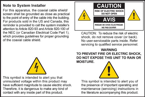
IMPORTANT SAFETY INSTRUCTIONS

Read These Instructions

Keep These Instructions

Heed All Warnings

Follow All Instructions

Power Source Warning
              A label on this product indicates the correct power source for this product. Operate this product only
              from an electrical outlet with the voltage and frequency indicated on the product label. If you are
              uncertain of the type of power supply to your home or business, consult your service provider or your
              local power company.
              The AC inlet on the unit must remain accessible and operable at all times.

Ground the Product
                        WARNING: Avoid electric shock and fire hazard! Do not defeat the safety purpose of
                        the polarized or grounding-type plug. A polarized plug has two blades with one wider
                        than the other. A grounding-type plug has two blades and a third grounding prong.
                        The wide blade or the third prong is provided for your safety. If the provided plug
                        does not fit into your outlet, consult an electrician for replacement of the obsolete
                        outlet.

              If this product connects to coaxial cable wiring, be sure the cable system is grounded (earthed). Grounding provides
              some protection against voltage surges and built-up static charges.

Protect the Product from Lightning
              For added protection, unplug this apparatus during lightning storms or when unused for long periods
              of time. In addition to disconnecting the AC power from the wall outlet, disconnect the signal inputs.

Verify the Power Source from the On/Off Power Light
              When the on/off power light is not illuminated, the apparatus may still be connected to the power
              source. The light goes out when the apparatus is turned off, regardless of whether it is still plugged into
              an AC power source.

Eliminate AC Mains Overloads
                        WARNING: Avoid electric shock and fire hazard! Do not overload AC mains, outlets,
                        extension cords, or integral convenience receptacles. For products that require battery
                        power or other power sources to operate them, refer to the operating instructions for
                        those products.

72-4017315-01 Rev B                                                                                                                  vii
IMPORTANT SAFETY INSTRUCTIONS
Prevent Power Cord Damage
Protect the power cord from being walked on or pinched, particularly at plugs, convenience
receptacles, and the point where the cord exits from the apparatus.
Handling Optional, Rechargeable Battery
This product may contain a rechargeable Lithium-Ion battery to provide stand-by operation in the
event of an AC power failure. Heed the following warning and see the instructions later in this guide
for handling, replacing, and disposing of the battery.
WARNING: There is danger of explosion if the battery is mishandled or incorrectly
replaced. Replace only with the same type of battery. Do not disassemble it or attempt
to recharge it outside the system. Do not crush, puncture, dispose of in fire, short the
external contacts, or expose to water or other liquids. Dispose of the battery in
accordance with local regulations and instructions from your service provider.
Provide Ventilation and Select a Location
Remove all packaging material before applying power to the product.
Do not block any ventilation openings. Install in accordance with the manufacturer's instructions.
Do not place this apparatus on a bed, sofa, rug, or similar surface.
Do not place this apparatus on an unstable surface.
Do not install near any heat sources such as radiators, heat registers, stoves, or other apparatus
(including amplifiers) that produce heat.
Do not install this apparatus in an enclosure, such as a bookcase or rack, unless the installation
provides proper ventilation.
Do not place entertainment devices (such as VCRs or DVDs), lamps, books, vases with liquids, or
other objects on top of this product.
Protect from Exposure to Moisture and Foreign Objects
Do not use this apparatus near water.
WARNING: Avoid electric shock and fire hazard! Do not expose this product to
liquids, rain, or moisture.
WARNING: Avoid electric shock and fire hazard! Unplug this product before cleaning.
Clean only with a dry cloth. Do not use a liquid cleaner or an aerosol cleaner. Do not
use a magnetic/static cleaning device (dust remover) to clean this product.
WARNING: Avoid electric shock and fire hazard! Never push objects through the
openings in this product. Foreign objects can cause electrical shorts that can result in
electric shock or fire.
viii 72-4017315-01 Rev B
IMPORTANT SAFETY INSTRUCTIONS

Accessories Warning
                       WARNING: Avoid electric shock and fire hazard! Only use attachments/accessories
                       specified by your service provider or the manufacturer.

Service Warnings
                       WARNING: Avoid electric shock! Do not open the cover of this product. Opening or
                       removing the cover may expose you to dangerous voltages. If you open the cover, your
                       warranty will be void. This product contains no user-serviceable parts. Refer all
                       servicing to qualified service personnel.

              Servicing is required when the apparatus has been damaged in any way, such as a power-supply cord
              or plug is damaged, liquid has been spilled or objects have fallen into the apparatus, the apparatus has
              been exposed to rain or moisture, does not operate normally, or has been dropped.

Check Product Safety
              Upon completion of any service or repairs to this product, the service technician must perform safety
              checks to determine that this product is in proper operating condition.

Protect the Product When Moving It
              Always disconnect the power source when moving the apparatus or connecting or disconnecting
              cables.

                       WARNING: Avoid personal injury and damage to this product! Use only with the cart,
                       stand, tripod, bracket, or table specified by the manufacturer or sold with the
                       apparatus. When a cart is used, use caution when moving the cart / apparatus
                       combination to avoid injury from tip-over.

                                                                                             20070802 Modem Cable with Recharge Battery

72-4017315-01 Rev B                                                                                                                   ix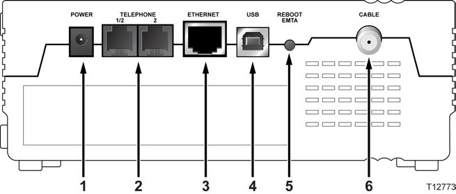
FCC Compliance
FCC Compliance
United States FCC Compliance
This device has been tested and found to comply with the limits for a Class B digital device,
pursuant to part 15 of the FCC Rules. These limits are designed to provide reasonable
protection against such interference in a residential installation. This equipment generates,
uses, and can radiate radio frequency energy. If not installed and used in accordance with the
instructions, it may cause harmful interference to radio communications. However, there is
no guarantee that interference will not occur in a particular installation. If this equipment
does cause harmful interference to radio or television reception, which can be determined by
turning the equipment OFF and ON, the user is encouraged to try to correct the interference
by one or more of the following measures:
Reorient or relocate the receiving antenna.
Increase the separation between the equipment and receiver.
Connect the equipment into an outlet on a circuit different from that to which the
receiver is connected.
Consult the cable company or an experienced radio/television technician for help.
Any changes or modifications not expressly approved by Cisco Systems, Inc., could void the
user's authority to operate the equipment.
The information shown in the FCC Declaration of Conformity paragraph below is a
requirement of the FCC and is intended to supply you with information regarding the FCC
approval of this device. The phone numbers listed are for FCC-related questions only and not
intended for questions regarding the connection or operation for this device. Please contact your cable
service provider for any questions you may have regarding the operation or installation of this device.
Declaration of Conformity
This device complies with Part 15 of FCC VoIP Cable Modem
Rules. Operation is subject to the following two Model: DPC2203C
conditions: 1) the device may not cause Manufactured by:
harmful interference, and 2) the device must Cisco Systems, Inc.
accept any interference received, including 5030 Sugarloaf Parkway
interference that may cause undesired Lawrenceville, Georgia 30044 USA
operation. Telephone: 678-277-1120
Canada EMI Regulation
This Class B digital apparatus complies with Canadian ICES-003.
Cet appareil numérique de la class B est conforme à la norme NMB-003 du Canada.
20060628 FCC Standard
72-4017315-01 Rev B xiContents
IMPORTANT SAFETY INSTRUCTIONS v
FCC Compliance xi
About This Guide xv
Chapter 1 Introducing the Model DPC2203C VoIP Cable Modem 1
DPC2203C Features ................................................................................................................. 2
DPC2203C Components.......................................................................................................... 4
Theory of Operation ................................................................................................................ 7
Chapter 2 Installing the DPC2203C for Internet Service 13
Before You Begin .................................................................................................................... 14
Install the Cable Modem ....................................................................................................... 18
Configure TCP/IP.................................................................................................................. 20
Install USB Drivers ................................................................................................................ 23
Chapter 3 Installing the DPC2203C for Telephone Service 25
Telephone Requirements ...................................................................................................... 26
About the Battery ................................................................................................................... 27
Mount the Cable Modem on a Wall (Optional) ................................................................. 29
Install the Cable Modem to Provide Telephone Service .................................................. 31
Chapter 4 Troubleshooting the Installation 35
Troubleshooting Overview................................................................................................... 37
Functions of Front Panel LED Status Indicators................................................................ 38
Powering Options .................................................................................................................. 41
No Downstream Signal Lock ............................................................................................... 43
Ranging Not Complete ......................................................................................................... 45
IP Connectivity Not Complete ............................................................................................. 47
Registration Not Complete ................................................................................................... 49
Troubleshooting for High-Speed Data Installations ......................................................... 51
Troubleshooting for Telephony Installations..................................................................... 54
72-4017315-01 Rev B xiiiContents
Chapter 5 Operating the DPC2203C 57
WebWizard ............................................................................................................................. 58
Appendix A Specifications 67
Technical Specifications ........................................................................................................ 68
Appendix B Cable Modem Warranty and RMA Information 73
Warranty and RMA Information ......................................................................................... 74
xiv 72-4017315-01 Rev BAbout This Guide
About This Guide
Introduction
This installation and operation guide applies to the Model DPC2203C voice over
Internet Protocol (VoIP) Cable Modems. These models are cable modems with an
embedded media terminal adapter (EMTA) including two RJ-11 telephone ports
supporting two-line voice services, a 10/100Base-T Ethernet port, and a USB 1.1 port
for high-speed data connectivity.
The DPC2203C is compatible with the following specifications:
Data Over Cable System Interface Specifications (DOCSIS®) 2.0 and 1.1
PacketCableTM 1.0 (upgradeable to PacketCable 1.1)
This guide provides the following design, performance, and technical information
for understanding basic VoIP and cable modem operation and function to
familiarize you with the DPC2203C:
Design and performance features
Theory of operation for cable modems
Procedures for installing, operating, maintaining, and troubleshooting the
DPC2203C using the Cable Modem Access Protection and WebWizard features
Appendixes that include technical specifications
Purpose
This installation and operation guide contains detailed instructions for installing,
operating, maintaining, and troubleshooting the DPC2203C.
Audience
This guide is written for cable service providers, system operators, cable modem
installers, system engineers, customer service representatives, cable modem
marketing personnel, and Cisco Service engineers.
72-4017315-01 Rev B xvAbout This Guide
Document Version
This is the second release of this document.
xvi 72-4017315-01 Rev B1 Chapter 1
Introducing the Model
DPC2203C VoIP Cable Modem
Introduction
The Model DPC2203C VoIP Cable Modem provides broadband
network operators with a cost-effective way to offer standard
telephone service along with high-speed data services to subscribers.
The DPC2203C features a highly integrated Embedded Multimedia
Terminal Adapter (EMTA) with two RJ-11 telephony ports for
conventional telephones or fax machines. In addition, the DPC2203C
contains both a 10/100Base-T Ethernet port and a USB 1.1 port to
provide connectivity for high-speed data services or other Internet
appliances. The DPC2203C modem also includes an internal Lithium-
Ion cartridge-style battery for convenient backup power.
This chapter provides an overview of the outstanding design and
performance features of the DPC2203C, the front and back panel
components of the cable modem, and a theory of operation for cable
modems for successful installation and operation of the cable modem.
This chapter also provides the requirements for the cable system and
the user’s site.
In This Chapter
DPC2203C Features ................................................................................ 2
DPC2203C Components ........................................................................ 4
Theory of Operation ............................................................................... 7
72-4017315-01 Rev B 1Chapter 1 Introducing the Model DPC2203C VoIP Cable Modem
DPC2203C Features
This section contains an overview of some of the design and performance features of
the DPC2203C.
Design and Performance Features
The DPC2203C is designed to meet DOCSIS® 2.0 and 1.1 specifications along with
PacketCable 1.0 specifications.
The following list provides some of the outstanding design and performance
features of the DPC2203C:
Attractive compact design
Embedded Multimedia Terminal Adapter (EMTA) that provides two lines of
voice services
Standard VoIP call signaling compliant with MGCP/NCS specifications
Software upgrades available to support session initiation protocol (SIP) call
signaling
G.711 and G.728 codecs (other codecs are available upon request)
Echo cancellation
Voice activation detection (VAD)
Comfort noise generation (CNG)
WebWizard browser-based graphical user interface for simple setup
Up to eight front-panel LED status indicators provide an easy-to-understand
display that shows cable modem status and real-time data transmission activity
Internet Protocol Security (IPSec) and AES-128 encryption options
Downloadable software for future upgrades
Bridged 10/100Base-T auto-sensing/auto-MDIX Ethernet port
USB 1.1 data port
CD-ROM containing a user guide and USB driver installation software
Simple network management protocol (SNMP) v1, v2c, and v3
Unit can be operated freestanding horizontally or vertically, or wall mounted
horizontally or vertically
2 72-4017315-01 Rev BDPC2203C Features
WebWizard
The DPC2203C includes the WebWizard, a browser-based interface that facilitates
cable modem set up and troubleshooting. The WebWizard verifies set-up and
troubleshooting results and eliminates the need to load additional setup software on
the consumer premise equipment (CPE). In addition, as many as eight front-panel
LED status indicators provide an informative and easy-to-understand display that
indicates cable modem status along with a visual feedback of real-time data
transmissions and modem operating status.
Note: For more information on the WebWizard feature, see WebWizard (on page
58).
72-4017315-01 Rev B 3Chapter 1 Introducing the Model DPC2203C VoIP Cable Modem
DPC2203C Components
Front Panel Description
The front panel of your cable modem provides status LEDs that indicate how well
and at what state your cable modem is operating. See Functions of Front Panel LED
Status Indicators (on page 38) for more information on front-panel LED status
indicator functions.
1 POWER – Illuminates solid green to indicate that AC power is being applied to
the cable modem. AC power must be available to recharge the optional battery.
2 DS (Downstream) – Indicates the status of the connection for receiving data.
Illuminates during normal operation
3 US (Upstream) – Indicates the status of the connection for sending data.
Illuminates during normal operation
4 ONLINE – Illuminates solid green when the cable modem is registered on the
network and fully operational. This indicator blinks to indicate one of the
following conditions:
The cable modem is booting up and not ready for data
The cable modem is scanning the network and attempting to register
The cable modem has lost registration on the network and will continue
blinking until it registers again
5 LINK – Illuminates solid green to indicate that an Ethernet/USB carrier is
present and blinks to indicate that Ethernet/USB data is being transferred
between the PC and the cable modem
6 TEL 1 – Illuminates solid green when telephony service is enabled. Blinks when
line 1 is in use
7 TEL 2 – Illuminates solid green when telephony service is enabled. Blinks when
line 2 is in use
8 BATTERY – Illuminates solid green to indicate that the battery is charged. Blinks
to indicate that the battery charge is low. Off when operating from battery
power, when the battery charge is depleted, or the battery is defective or not
installed
4 72-4017315-01 Rev BDPC2203C Components
Notes:
After the cable modem is successfully registered on the network, the POWER
(LED 1), DS (LED 2), US (LED 3), and ONLINE (LED 4) LEDs illuminate
continuously to indicate that the cable mode is active and fully operational
LEDs may behave differently when the cable modem is running on battery
power (without AC power-optional model only). Most LEDs are disabled if
the unit is operating on battery power. In this mode, the POWER LED blinks
to indicate that the unit is operating under battery power but AC power has
failed
72-4017315-01 Rev B 5Chapter 1 Introducing the Model DPC2203C VoIP Cable Modem
Back Panel Description
The following illustration shows the description and function of the back panel
components on the DPC2203C.
Important: Do not connect your PC to both the Ethernet and USB ports at the same
time. Your modem will not function properly if both the Ethernet and USB ports are
connected to your PC at the same time.
1 POWER – Connects the cable modem to the AC power supply that is provided
with your cable modem
CAUTION:
Avoid damage to your equipment. Only use the AC power adapter that is
provided with your cable modem.
2 TEL 1/TEL 2 – RJ-11 telephone ports connect to home telephone wiring to
conventional telephones or fax machines
3 ETHERNET – RJ-45 Ethernet port connects to the 10/100base-T Ethernet port on
your PC or your home network
4 USB – 12 Mbps USB 1.1 port connects to the USB port on your PC
5 REBOOT EMTA – Pressing this switch reboots the EMTA. Pressing this switch
for more than three seconds resets the device to factory default values and
reboots the EMTA
CAUTION:
The Reboot EMTA button is for maintenance purposes only. Do not use
unless instructed to do so by your service provider. Doing so may cause
you to lose any cable modem settings you have selected.
6 CABLE – F-Connector connects to an active signal from your service provider
6 72-4017315-01 Rev BTheory of Operation
Theory of Operation
This section summarizes the theory of operation for cable modems and provides a
high-level overview of the operational stages for the cable modem. Reading this
chapter provides a better understanding of how cable modems operate.
Note: This section is not intended to be a specification for the cable modem.
Cable Modem Initialization
A cable modem must establish a communication link with the headend before it
becomes fully operational. This section describes the eight DOCSIS-required
operational stages through which a cable modem progresses in establishing this
communication link.
This section provides a detailed explanation of each of the following operational
stages.
1 Scan for Downstream Channel
2 Obtain Upstream Parameters
3 Adjust Timing Offset and Power Level
4 Establish IP Connectivity
5 Establish Time of Day
6 Transfer Operational Parameters
7 Register with the Cable Modem Termination System (CMTS)
8 Initialize Baseline Privacy
Scan for Downstream Channel
When a cable modem powers on, the cable modem starts to scan the network for the
CMTS downstream channel. The downstream channel is the channel used to send
data from the CMTS to the cable modem. The cable modem identifies a valid
downstream data channel as a channel that has QAM signal timing, forward error
correction (FEC) framing, MPEG packets, and downstream media access control
(MAC) messages. The CMTS terminates the cable modem signal at an upstream
location and provides the cable modem with a network connection.
This section discusses the cable modem downstream scanning routine along with
two features that speed up the downstream scanning process: the Valid CMTS
Frequency Table and the WebWizard Gscan function.
72-4017315-01 Rev B 7Chapter 1 Introducing the Model DPC2203C VoIP Cable Modem
Downstream Scanning Routine
The cable modem starts its own standard scanning algorithm. The scanning routine
of the cable modem is now optimized to seek out the CMTS downstream channel as
quickly as possible. The actual scanning process varies slightly depending on the
television frequency channel plan for your particular country.
For example, in North America the standard downstream scanning routine works in
three phases and may take several minutes. The cable modem stops scanning when
the cable modem finds a valid downstream data channel. The cable modem then
proceeds to the next stage: obtain upstream parameters.
In this example, the cable modem scans for the downstream channel in the following
three phases.
1 The cable modem starts to scan the network at 453 MHz and scans up in 6 MHz
increments to end at 855 MHz.
2 The cable modem starts scanning the network at 447 MHz and then scans in 6
MHz increments down to 93 MHz.
3 The process is then repeated for the National Television Systems Committee
(NTSC) Harmonic Related Carrier (HRC) frequency plan in 6.0003 MHz
increments.
Important: There are specialized frequency plans to optimize the acquisition of the
downstream signal that depend on the video format used in the country of
deployment. Check with the representative who handles your account for more
information about alternate scanning routines outside of North America.
Improved Downstream Scanning Features
The cable modems contain two outstanding features that can speed up the scanning
process: the Valid CMTS Frequency Table and the WebWizard Gscan function.
Valid CMTS Frequency Table
The Valid CMTS Frequency Table feature works automatically and requires no user
intervention. When a cable modem finds a valid downstream data channel so that it
can complete the ranging stage, the cable modem stores this frequency in nonvolatile
memory (NVM). The cable modem checks the frequencies stored in NVM before
starting the standard scanning algorithm to search for a downstream data channel.
Note: The cable modems store up to 10 valid CMTS frequencies in the table.
The standard scanning algorithm also regularly interrupts progressive scanning to
check the last known valid CMTS frequency, and then the cable modem resumes its
standard scanning algorithm where it left off.
8 72-4017315-01 Rev BTheory of Operation
WebWizard Gscan Function
When installing a cable modem, you can speed up the process by using the
WebWizard Gscan function. To access the WebWizard Gscan function, you must
first connect a PC to the cable modem. Then, using your Web Browser, you can
access the WebWizard Gscan function.
Note: For more information on the WebWizard Gscan function, see WebWizard (on
page 58).
Obtain Upstream Parameters
After finding a valid downstream data channel, the cable modem reviews the
upstream parameters needed to perform the next stage: ranging and automatic
adjustments. The upstream parameters enable the cable modem to send data to the
CMTS. When the cable modem finds the correct upstream parameters, the cable
modem proceeds to the ranging and automatic adjustments stage.
If the cable modem cannot find valid upstream parameters, it returns to the scan for
downstream channel stage. Then the cable modem starts to scan again at the next
available channel.
Adjust Timing Offset and Power Level
After the cable modem obtains its upstream parameters, it begins the ranging and
automatic adjustments stage. In this stage, the cable modem adjusts the timing offset
and the power level for communicating with the CMTS.
The cable modem uses MAC messages to determine the upstream channel frequency
and adjusts timing offsets to verify the synchronized timing between the CMTS and
the cable modem. This process also determines the upstream signal transmit power
level from the cable modem to communicate with the CMTS.
After the cable modem completes the ranging stage and registers with the CMTS, it
repeats this routine regularly to fine-tune the settings established in the previous
stages. These regular adjustments are considered routine maintenance and do not
affect normal operations of your cable modem service.
Note: If the cable modem fails to achieve the proper settings when performing
ranging and automatic adjustments, it terminates the session and restarts the
initialization process at the scan for downstream channel stage.
72-4017315-01 Rev B 9Chapter 1 Introducing the Model DPC2203C VoIP Cable Modem
Establish IP Connectivity
After completing the ranging and automatic adjustments stage, the cable modem
attempts to establish Internet Protocol (IP) connectivity. In this stage, the cable
modem obtains network connection information and a cable modem IP address from
provisioning servers that are located on the network side of the CMTS interface.
The cable modem achieves this connectivity using a protocol called Dynamic Host
Configuration Protocol (DHCP).
Note: If the cable modem fails to establish IP connectivity, it terminates the session
and restarts the initialization process at the scan for downstream channel stage.
Establish Time of Day
After the cable modem establishes IP connectivity, the cable modem requests the
time of day from the network interface. This stage allows the cable modem to know
the system time so that when the cable modem logs an event, it associates a time
with that event.
Note: The cable modem can operate without establishing the time of day; however, it
logs the failure, generates an alert to simple network management protocol (SNMP),
and then proceeds to the next stage. The cable modem periodically repeats this stage
to attempt to establish the time of day.
Transfer Operational Parameters
After the cable modem requests the time of day, the cable modem then requests the
transfer of the cable modem configuration file. The cable modem makes the request
to the Trivial File Transfer Protocol (TFTP) server. The configuration file contains
parameters for how the system operator wants the cable modem to function on the
cable network.
Typical operation parameters for the cable modem include:
Upstream and downstream rate limits
Specific frequencies
Number of CPE devices
IP filters
Port filters
MAC/LLC filters
Vendor-specific settings
Software version installed
10 72-4017315-01 Rev BTheory of Operation
Notes:
If the cable modem does not contain the software version requested by the
configuration file, the cable modem requests that software version from the TFTP
server. When the software installation is complete, the cable modem restarts the
entire initialization process again at the scan for downstream channel stage.
If the system instructs the cable modem to use a different frequency from what
the cable modem is currently using, the cable modem cannot proceed to the next
stage: register with the CMTS. The cable modem must repeat the scan for
downstream channel stage or reestablish ranging on a new upstream channel.
Register with the CMTS
After the cable modem completes the transfer operational parameters stage, the
cable modem now registers with the CMTS. After the cable modem receives a reply
from the CMTS confirming its registration request, the cable modem is now
authorized to forward network traffic from the CPE.
Initialize Baseline Privacy
Baseline Privacy functions in the CMTS and in the cable modem are used to encrypt
data being transferred to and from the cable modem. Following registration with the
CMTS, if the cable modem is provisioned to run with baseline privacy, the cable
modem must initialize baseline privacy operations. Using baseline privacy means
that all data transferred is secure.
72-4017315-01 Rev B 112 Chapter 2
Installing the DPC2203C for
Internet Service
Introduction
This chapter provides information and procedures to assist you in
placing, installing, configuring, operating, and troubleshooting the
DPC2203C for high-speed Internet service.
In This Chapter
Before You Begin................................................................................... 14
Install the Cable Modem ...................................................................... 18
Configure TCP/IP ................................................................................ 20
Install USB Drivers ............................................................................... 23
72-4017315-01 Rev B 13Chapter 2 Installing the DPC2203C for Internet Service
Before You Begin
This section provides the minimum requirements for installing the DPC2203C on
your system and at user sites.
Cable System Requirements
To allow successful installation and operation, verify that your system meets the
following minimum requirements:
DOCSIS 2.0 or 1.1
PacketCable 1.0
Important: This guide does not cover installing cable modem network and headend
equipment on your system. For information on installing network and headend
equipment, refer to the documentation provided with your network and headend
equipment.
Equipment Checklist
Before you install the cable modem, check the items in the carton. The carton
contains the following items, except as noted:
One cable modem (DPC2203C)
One Ethernet cable (CAT5/RJ-45)
One USB cable
One power adapter with power cord
One CD-ROM containing the user guide and the USB drivers
One or two lithium-ion cartridge batteries (optional models only)
Notes:
An additional cable signal splitter and coaxial cable are needed to connect to a
VCR, a digital set-top converter, or a TV to the same cable connection as your
cable modem.
Cables and other equipment needed for telephony service must be purchased
separately.
14 72-4017315-01 Rev BBefore You Begin
Hardware and Software Requirements
This section provides hardware and software requirements for connecting your
cable modem to a PC for high-speed Internet service.
Note: You will also need an active cable input line and an Internet connection.
PC Requirements
A PC with a Pentium MMX 133 processor or greater
32 MB of RAM
Netscape or Internet Explorer
CD-ROM drive
Macintosh Requirements
MAC OS 7.5 or later
32 MB of RAM
Ethernet Requirements
A PC with Microsoft Windows 95 operating system (or later) with TCP/IP
protocol installed, or an Apple Macintosh computer with TCP/IP protocol
installed
An active 10/100Base-T Ethernet network interface card (NIC) installed in your
PC
USB Requirements
A PC with a Microsoft Windows 2000, Windows XP, or Windows Vista
operating system
A host USB port installed in your PC
Telephony Requirements
RJ-11 telephone jacks to connect to home telephone wiring to conventional
telephones or fax machines
Contacting Your Local Service Provider
Before you can use your cable modem, you need to have a high-speed Internet
access account. If you do not have a high-speed Internet access account, you need to
set up an account with your local service provider. Choose one of the two options in
this section.
72-4017315-01 Rev B 15Chapter 2 Installing the DPC2203C for Internet Service
I Do Not Have a High-Speed Internet Access Account
If you do not have a high-speed Internet access account, your service provider will
set up your account and become your Internet Service Provider (ISP). Internet access
enables you to send and receive e-mail, access the World Wide Web, and receive
other Internet services.
You will need to give your service provider the following information:
The serial number of the modem
The Media Access Control (MAC) address of the modem
These numbers appear on a bar code label located on the cable modem. The serial
number consists of a series of alphanumeric characters preceded by S/N. The MAC
address consists of a series of alphanumeric characters preceded by . The following
illustration shows a sample bar code label.
Note: Due to minor design changes, the label on your cable modem may differ
slightly from the one shown here.
Write down these numbers in the space provided here.
Serial Number _______________________
MAC Address _______________________
16 72-4017315-01 Rev BBefore You Begin
I Already Have an Existing High-Speed Internet Access Account
If you have an existing high-speed Internet access account, you must give your
service provider the serial number and the MAC address of the cable modem. Refer
to the serial number and MAC address information listed previously in this section.
Note: You may not be able to continue to use your existing e-mail account with your
cable modem. Contact your service provider for more information.
The ideal location for your cable modem is where it has access to outlets and other
devices. Think about the layout of your home or office, and consult with your
service provider to select the best location for your cable modem. Read this user
guide thoroughly before you decide where to place your cable modem.
Consider these recommendations:
Position your PC and cable modem so that they are located near an AC power
outlet.
Position your PC and cable modem so that they are located near an existing cable
input connection to eliminate the need for an additional cable outlet. There
should be plenty of room to guide the cables away from the modem and the PC
without straining or crimping them.
Airflow around the cable modem should not be restricted.
Choose a location that protects the cable modem from accidental disturbance or
harm.
72-4017315-01 Rev B 17Chapter 2 Installing the DPC2203C for Internet Service
Install the Cable Modem
Installation Diagram
The following diagram illustrates one of the various installation and connection
options that are available to you.
Note: Professional installation may be available. Contact your local service provider
for further assistance.
Installing the Modem
The following installation procedure ensures proper cable modem setup and
configuration.
WARNING:
To avoid personal injury or damage to your equipment, follow these steps in
the exact order shown.
1 Choose an appropriate and safe location to install the cable modem (close to a
power source, an active cable connection, your PC [if using high-speed Internet]
and your telephone lines [if using VoIP]).
Note: The cable modem can be positioned freestanding horizontally or vertically,
or it can be wall-mounted horizontally or vertically.
2 Power off your PC and unplug it from the power source.
WARNING:
Avoid electric shock! Failure to unplug your PC from the power source may
create a shock hazard.
18 72-4017315-01 Rev BInstall the Cable Modem
3 Connect your PC to either the Ethernet port or the USB port using the appropriate
data cable.
Note: You can connect two separate PCs to the cable modem at the same time by
connecting one to the Ethernet port and one to the USB port.
4 Insert the AC power cord into the power connector on the back of the cable
modem, and then plug the other end into an AC power source.
5 Plug in and power on your PC.
WARNING:
To avoid electric shock, disconnect your telephone company service at the
network interface device (demarcation point) before connecting the cable
modem telephone ports to your home telephone jacks.
6 Connect telephone port TEL1 (or Line 1 depending on your model) to your home
telephone jack. If your home is wired for a second telephone circuit, the connect
TEL2 (or Line 2 depending on your model) to the second telephone circuit.
7 Connect the active RF coaxial cable to the CABLE connector.
Note: Use an optional cable signal splitter to add a TV, a DHCT or set-top
converter, or a VCR.
8 The cable modem will then begin an automatic search to locate and sign on to the
broadband data network.
Note: This process may take up to 5 minutes. The modem will be ready for use
when the ONLINE LED status indicator on the front panel stops blinking and
illuminates continuously.
9 Choose one of the following options:
To configure the TCP/IP protocol for Ethernet, go to Configure TCP/IP (on
page 20).
To install the USB Drivers for USB, go to Install USB Drivers (on page 23).
72-4017315-01 Rev B 19Chapter 2 Installing the DPC2203C for Internet Service
Configure TCP/IP
This section contains instructions for configuring the cable modem to run in
Microsoft Windows or Macintosh environments. In addition, TCP/IP protocol in a
Microsoft Windows environment is different for the Windows 95, 98, 98SE, ME,
2000, or XP versions. Go to the appropriate section and follow the instructions to
configure the TCP/IP protocol.
Configuring TCP/IP on Windows XP Systems
1 Click Start, and depending on your Start menu setup, choose one of the
following options:
If you are using the Windows XP Default Start Menu, select Connect to,
choose Show all connections, and then go to step 2.
If you are using the Windows XP Classic Start Menu, select Settings, choose
Network Connections, click Local Area Connection, and then go to step 3.
2 Double-click the Local Area Connection icon in the LAN or High-Speed Internet
section of the Network Connections window.
3 Click Properties in the Local Area Connection Status window.
4 Click Internet Protocol (TCP/IP), and then click Properties in the Local Area
Connection Properties window.
5 Select both Obtain an IP address automatically and Obtain DNS server address
automatically in the Internet Protocol (TCP/IP) Properties window, and then
click OK.
6 Click Yes to restart your computer when the Local Network window opens. The
computer restarts. The TCP/IP protocol is now configured on your PC, and your
Ethernet devices are ready for use.
7 Try to access the Internet. If you cannot access the Internet, go to
Troubleshooting the Installation (on page 35). If you still cannot access the
Internet, contact your service provider for further assistance.
Configuring TCP/IP on Windows 2000 Systems
1 Click Start, select Settings, and choose Network and Dial-up Connections.
2 Double-click the Local Area Connection icon in the Network and Dial-up
Connections window.
3 Click Properties in the Local Area Connection Status window.
4 Click Internet Protocol (TCP/IP) in the Local Area Connection Properties
window, and then click Properties.
5 Select both Obtain an IP address automatically and Obtain DNS server address
automatically in the Internet Protocol (TCP/IP) Properties window, and then
click OK.
20 72-4017315-01 Rev BConfigure TCP/IP
6 Click Yes to restart your computer when the Local Network window opens. The
computer restarts. The TCP/IP protocol is now configured on your PC, and your
Ethernet devices are ready for use.
7 Try to access the Internet. If you cannot access the Internet, go to
Troubleshooting the Installation (on page 35). If you still cannot access the
Internet, contact your service provider for further assistance.
Configuring TCP/IP on Windows 95, 98, 98SE, or ME Systems
1 Click Start, select Settings, and choose Control Panel.
2 Double-click the Network icon in the Control Panel window.
3 Read the list of installed network components under the Configuration tab to
verify that your PC contains the TCP/IP protocol/Ethernet adapter.
4 Is TCP/IP protocol listed in the installed network components list?
If yes, go to step 7.
If no, click Add, click Protocol, click Add, and then go to step 5.
5 Click Microsoft in the Manufacturers list.
6 Click TCP/IP in the Network Protocols list, and then click OK.
7 Click the TCP/IP Ethernet Adapter protocol, and then choose Properties.
8 Click the IP Address tab, and then select Obtain an IP address automatically.
9 Click the Gateway tab and verify that these fields are empty. If they are not
empty, highlight and delete all information from the fields.
10 Click the DNS Configuration tab, and then select Disable DNS.
11 Click OK.
12 Click OK when the system finishes copying the files, and then close all
networking windows.
13 Click YES to restart your computer when the System Settings Change dialog box
opens. The computer restarts. The TCP/IP protocol is now configured on your
PC, and your Ethernet devices are ready for use.
14 Try to access the Internet. If you cannot access the Internet, go to
Troubleshooting the Installation (on page 35). If you still cannot access the
Internet, contact your service provider for further assistance.
72-4017315-01 Rev B 21Chapter 2 Installing the DPC2203C for Internet Service
Configuring TCP/IP on Macintosh Systems
1 Click the Apple icon in the upper-left corner of the Finder. Scroll down to
Control Panels, and then click TCP/IP.
2 Click Edit on the Finder at the top of the screen. Scroll down to the bottom of the
menu, and then click User Mode.
3 Click Advanced in the User Mode window, and then click OK.
4 Click the Up/Down selector arrows located to the right of the Connect Via
section of the TCP/IP window, and then click Using DHCP Server.
5 Click Options in the TCP/IP window, and then click Active in the TCP/IP
Options window.
Note: Make sure that the Load only when needed option is unchecked.
6 Verify that the Use 802.3 option located in the upper-right corner of the TCP/IP
window is unchecked. If there is a check mark in the option, uncheck the option,
and then click Info in the lower-left corner.
7 Is there a Hardware Address listed in this window?
If yes, click OK. To close the TCP/IP Control Panel window, click File, and
then scroll down to click Close. You have completed this procedure.
If no, you must power off your Macintosh.
8 With the power off, simultaneously press and hold down the Command
(Apple), Option, P, and R keys on your keyboard. Keeping those keys pressed
down, power on your Macintosh but do not release these keys until you hear the
Apple chime at least three times, then release the keys and let the computer
restart.
9 When your computer fully reboots, repeat steps 1 through 7 to verify that all
TCP/IP settings are correct. If your computer still does not have a Hardware
Address, contact your authorized Apple dealer or Apple technical support center
for further assistance.
22 72-4017315-01 Rev BInstall USB Drivers
Install USB Drivers
This section contains instructions for installing the cable modem USB drivers if your
PC is equipped with a USB interface and a Microsoft Windows 2000 or Windows XP
operating system. The USB driver installation procedures are different for each
operating system. Follow the appropriate instructions in this section for your
operating system.
Note: If your PC does not have a USB interface, you may skip this section.
Installing USB Drivers on Windows XP Systems
1 Insert the USB Cable Modem Driver Installation Disk into the CD-ROM drive
of your PC.
2 Wait until the POWER and ONLINE LED status indicators on the front panel of
the cable modem illuminate solid green.
3 Select Install from a list or specific location (Advanced) in the Found New
Hardware Wizard window, and then click Next.
4 Select Search removable media (floppy, CD-ROM) in the Found New
Hardware Wizard window, and then click Next.
5 Click Continue Anyway in the Hardware Installation window to continue the
installation. The Found New Hardware Wizard window reopens with a message
that the installation has finished.
6 Click Finish to close the Found New Hardware Wizard window. The USB
drivers are installed on your PC, and your USB devices are ready for use.
7 Try to access the Internet. If you cannot access the Internet, go to
Troubleshooting the Installation (on page 35). If you still cannot access the
Internet, contact your service provider for further assistance.
Installing USB Drivers on Windows 2000 Systems
1 Insert the USB Cable Modem Driver Installation Disk into the CD-ROM drive
of your PC.
2 Wait until the POWER and ONLINE LED status indicators on the front panel of
the cable modem illuminate solid green.
3 Click Next in the Found New Hardware Wizard window.
4 Select Search for a suitable driver for my device (recommended) in the Found
New Hardware Wizard window, and then click Next.
5 Select CD-ROM drives in the Found New Hardware Wizard window, and then
click Next.
6 Click Next in the Found New Hardware Wizard window. The system searches
for the driver file for your hardware device.
72-4017315-01 Rev B 23Chapter 2 Installing the DPC2203C for Internet Service
7 After the system finds the USB driver, the Digital Signature Not Found window
opens and displays a confirmation message to continue the installation.
8 Click Yes to continue the installation. The Found New Hardware Wizard
window reopens with a message that the installation is complete.
9 Click Finish to close the Found New Hardware Wizard window. The USB
drivers are installed on your PC, and your USB devices are ready for use.
10 Try to access the Internet. If you cannot access the Internet, go to
Troubleshooting the Installation (on page 35). If you still cannot access the
Internet, contact your service provider for further assistance.
Installing USB Drivers on Windows 98SE and Windows ME Systems
1 Insert the USB Cable Modem Driver Installation Disk into the CD-ROM drive
of your PC.
2 Wait until the POWER and ONLINE LED status indicators on the front panel of
the cable modem illuminate solid green. The Add New Hardware Wizard
window opens.
3 Click Next in the Add New Hardware Wizard window.
4 Select Search for the best driver for your device (Recommended) in the Add
New Hardware Wizard window, and then click Next.
5 Select CD-ROM drive in the Add New Hardware Wizard window, and then
click Next.
6 Select The updated driver (Recommended) in the Add New Hardware Wizard
window, and then click Next.
7 Click Next in the Add New Hardware Wizard window. The Copying Files
window opens. After 10 to 20 seconds have passed, the Add New Hardware
Wizard window reopens.
8 Click Finish. The USB driver installation is complete.
24 72-4017315-01 Rev B3 Chapter 3
Installing the DPC2203C for
Telephone Service
Introduction
This chapter provides procedures to assist you in placing, installing,
configuring, operating, and troubleshooting the DPC2203C for
telephone service.
In This Chapter
Telephone Requirements ..................................................................... 26
About the Battery .................................................................................. 27
Mount the Cable Modem on a Wall (Optional) ................................ 29
Install the Cable Modem to Provide Telephone Service ................. 31
72-4017315-01 Rev B 25Chapter 3 Installing the DPC2203C for Telephone Service
Telephone Requirements
This section provides hardware and software requirements for utilizing your cable
modem for telephone service.
Number of Telephone Devices
The RJ-11 telephone-style connectors on the cable modem can each provide
telephone service to multiple telephones, fax machines, and analog modems.
The maximum number of telephone devices connected to each RJ-11 port is limited
by the total Ringing Load of the telephone devices that are connected. Many
telephone devices are marked with a Ringer Equivalent Number (REN). Each
telephone port on the cable modem can support up to a 5 REN load.
The sum of the REN load on all of the telephone devices attached to each port must
not exceed 5 REN.
Telephone Device Types
You can use telephone devices that are not labeled with a REN number, but the
maximum number of attached telephone devices cannot be accurately calculated.
With telephone devices that are not labeled, each device should be connected and
the ring signal should be tested before adding more devices. If too many telephone
devices are attached and the ring signal can no longer be heard, telephone devices
should be removed until the ring signal works properly.
Telephones, fax machines, and other telephone devices should use the center 2 pins
of the RJ-11 connectors to connect to the cable modem telephone ports. Some
telephones use other pins on the RJ-11 connectors and require adapters in order to
work.
Dialing Requirements
All your telephones should be set to use DTMF dialing. Pulse dialing is typically not
enabled by your local provider.
Telephone Wiring Requirements
The cable modem supports interior telephone wiring. The maximum distance from
the unit to the most distant telephone device must not exceed 1000 feet (300 meters).
Use 26-gauge twisted-pair, or larger, telephone wiring.
Important: Connection to an existing or a new permanently installed home
telephone wiring network must be done by a qualified installer.
26 72-4017315-01 Rev BAbout the Battery
About the Battery
Your modem includes a rechargeable Lithium-Ion battery to provide stand-by
operation in the event of an AC power failure. You can replace the battery without
the use of any tools.
WARNING:
There is danger of explosion if the battery is mishandled or incorrectly
replaced. Replace only with the same type of battery. Do not disassemble it or
attempt to recharge the battery outside the system. Do not crush, puncture,
dispose of in a fire, short external contacts, or expose to water or other liquids.
Dispose of the battery in accordance with local regulations and instructions
from your service provider.
Charging the Batteries
The battery begins to charge automatically as soon as you attach the modem to the
AC electrical outlet. When you first plug in the modem, the POWER LED status
indicator illuminates.
Important: It may take as long as 24 hours for the battery to charge fully.
Using the Modem Without a Battery
If you want, you can use the modem without a battery. If you need to remove the
battery, follow the procedures found in Removing and Replacing the Batteries.
Important: If you choose to operate your modem without a battery, you risk losing
your telephone service during a power outage.
Replacing the Batteries
Under normal circumstances, the battery should last for several years. The
BATTERY LED status indicator turns off to indicate that the battery should be
replaced soon. Contact your service provider to obtain replacement batteries and for
disposal instructions.
Note: Follow the steps found in Removing and Replacing the Battery (on page 28) to
remove and replace the battery.
72-4017315-01 Rev B 27Chapter 3 Installing the DPC2203C for Telephone Service
Location of Battery
The following illustration shows the location of the battery on the DPC2203C.
Removing and Replacing the Battery
Follow these steps to remove and replace the battery. You can remove and replace
the battery without disconnecting the AC power source.
1 Carefully turn the modem over.
2 Gently release the latch to open the battery cover and gain access to the battery
compartment.
3 Grasp the plastic strip on the front of the battery and gently slide the battery
forward to remove it from the battery compartment.
4 Insert a new battery into the battery compartment.
5 Close the battery compartment door. The battery lock will automatically re-
engage.
Important! It can take as long as 24 hours for the battery to charge fully.
Note: Dispose of the battery in accordance with local regulations and
instructions from your service provider.
28 72-4017315-01 Rev BYou can also read