EPP-360 Plasma Power Source - Instruction Manual
←
→
Page content transcription
If your browser does not render page correctly, please read the page content below

EPP-360
Plasma Power Source

Instruction Manual

0558007676           04/2009
Be sure this information reaches the operator.
                      You can get extra copies through your supplier.

                                             caution
  These INSTRUCTIONS are for experienced operators. If you are not fully familiar with the
  principles of operation and safe practices for arc welding and cutting equipment, we urge
  you to read our booklet, “Precautions and Safe Practices for Arc Welding, Cutting, and
  Gouging,” Form 52-529. Do NOT permit untrained persons to install, operate, or maintain
  this equipment. Do NOT attempt to install or operate this equipment until you have read
  and fully understand these instructions. If you do not fully understand these instructions,
  contact your supplier for further information. Be sure to read the Safety Precautions be-
  fore installing or operating this equipment.

                                      USER RESPONSIBILITY
This equipment will perform in conformity with the description thereof contained in this manual and accompa-
nying labels and/or inserts when installed, operated, maintained and repaired in accordance with the instruc-
tions provided. This equipment must be checked periodically. Malfunctioning or poorly maintained equipment
should not be used. Parts that are broken, missing, worn, distorted or contaminated should be replaced imme-
diately. Should such repair or replacement become necessary, the manufacturer recommends that a telephone
or written request for service advice be made to the Authorized Distributor from whom it was purchased.

This equipment or any of its parts should not be altered without the prior written approval of the manufacturer.
The user of this equipment shall have the sole responsibility for any malfunction which results from improper
use, faulty maintenance, damage, improper repair or alteration by anyone other than the manufacturer or a ser-
vice facility designated by the manufacturer.

      READ AND UNDERSTAND THE INSTRUCTION MANUAL BEFORE INSTALLING OR OPERATING.

                                     PROTECT YOURSELF AND OTHERS!
table of contents
Section / Title Page
1.0 Safety Precautions . . . . . . . . . . . . . . . . . . . . . . . . . . . . . . . . . . . . . . . . . . . . . . . . . . . . . . . . . . . . . . . . . . . . . . . . . . . . . . . . . . . 5
1.1 Safety - English . . . . . . . . . . . . . . . . . . . . . . . . . . . . . . . . . . . . . . . . . . . . . . . . . . . . . . . . . . . . . . . . . . . . . . . . . . . . . . . . . . 5
1.2 Safety - Spanish . . . . . . . . . . . . . . . . . . . . . . . . . . . . . . . . . . . . . . . . . . . . . . . . . . . . . . . . . . . . . . . . . . . . . . . . . . . . . . . . . 9
1.3 Safety - French . . . . . . . . . . . . . . . . . . . . . . . . . . . . . . . . . . . . . . . . . . . . . . . . . . . . . . . . . . . . . . . . . . . . . . . . . . . . . . . . . 13
2.0 Description . . . . . . . . . . . . . . . . . . . . . . . . . . . . . . . . . . . . . . . . . . . . . . . . . . . . . . . . . . . . . . . . . . . . . . . . . . . . . . . . . . . . . . . . . 17
2.1 Introduction . . . . . . . . . . . . . . . . . . . . . . . . . . . . . . . . . . . . . . . . . . . . . . . . . . . . . . . . . . . . . . . . . . . . . . . . . . . . . . . . . . . 17
2.2 General Specifications . . . . . . . . . . . . . . . . . . . . . . . . . . . . . . . . . . . . . . . . . . . . . . . . . . . . . . . . . . . . . . . . . . . . . . . . . . 17
2.3 Dimensions and Weight . . . . . . . . . . . . . . . . . . . . . . . . . . . . . . . . . . . . . . . . . . . . . . . . . . . . . . . . . . . . . . . . . . . . . . . . 18
3.0 Installation . . . . . . . . . . . . . . . . . . . . . . . . . . . . . . . . . . . . . . . . . . . . . . . . . . . . . . . . . . . . . . . . . . . . . . . . . . . . . . . . . . . . . . . . . . 19
3.1 General . . . . . . . . . . . . . . . . . . . . . . . . . . . . . . . . . . . . . . . . . . . . . . . . . . . . . . . . . . . . . . . . . . . . . . . . . . . . . . . . . . . . . . . . 19
3.2 Unpacking . . . . . . . . . . . . . . . . . . . . . . . . . . . . . . . . . . . . . . . . . . . . . . . . . . . . . . . . . . . . . . . . . . . . . . . . . . . . . . . . . . . . . 19
3.3 Placement . . . . . . . . . . . . . . . . . . . . . . . . . . . . . . . . . . . . . . . . . . . . . . . . . . . . . . . . . . . . . . . . . . . . . . . . . . . . . . . . . . . . . 19
3.4 Input Power Connection . . . . . . . . . . . . . . . . . . . . . . . . . . . . . . . . . . . . . . . . . . . . . . . . . . . . . . . . . . . . . . . . . . . . . . . 20
3.5 Output Connections . . . . . . . . . . . . . . . . . . . . . . . . . . . . . . . . . . . . . . . . . . . . . . . . . . . . . . . . . . . . . . . . . . . . . . . . . . . 22
3.6 Parallel Installation . . . . . . . . . . . . . . . . . . . . . . . . . . . . . . . . . . . . . . . . . . . . . . . . . . . . . . . . . . . . . . . . . . . . . . . . . . . . . 24
3.7 Interface Cable Connectors . . . . . . . . . . . . . . . . . . . . . . . . . . . . . . . . . . . . . . . . . . . . . . . . . . . . . . . . . . . . . . . . . . . . . 26
4.0 Operation . . . . . . . . . . . . . . . . . . . . . . . . . . . . . . . . . . . . . . . . . . . . . . . . . . . . . . . . . . . . . . . . . . . . . . . . . . . . . . . . . . . . . . . . . . . 29
4.1 EPP-360 Block Diagram . . . . . . . . . . . . . . . . . . . . . . . . . . . . . . . . . . . . . . . . . . . . . . . . . . . . . . . . . . . . . . . . . . . . . . . . . 29
4.2 Control Panel . . . . . . . . . . . . . . . . . . . . . . . . . . . . . . . . . . . . . . . . . . . . . . . . . . . . . . . . . . . . . . . . . . . . . . . . . . . . . . . . . . 30
4.3 Modes of Operation . . . . . . . . . . . . . . . . . . . . . . . . . . . . . . . . . . . . . . . . . . . . . . . . . . . . . . . . . . . . . . . . . . . . . . . . . . . . 32
4.4 Sequence of Operation . . . . . . . . . . . . . . . . . . . . . . . . . . . . . . . . . . . . . . . . . . . . . . . . . . . . . . . . . . . . . . . . . . . . . . . . . 35
5.0 Maintenance . . . . . . . . . . . . . . . . . . . . . . . . . . . . . . . . . . . . . . . . . . . . . . . . . . . . . . . . . . . . . . . . . . . . . . . . . . . . . . . . . . . . . . . 37
5.1 General . . . . . . . . . . . . . . . . . . . . . . . . . . . . . . . . . . . . . . . . . . . . . . . . . . . . . . . . . . . . . . . . . . . . . . . . . . . . . . . . . . . . . . . . 37
5.2 Cleaning . . . . . . . . . . . . . . . . . . . . . . . . . . . . . . . . . . . . . . . . . . . . . . . . . . . . . . . . . . . . . . . . . . . . . . . . . . . . . . . . . . . . . . . 37
6.0 Troubleshooting . . . . . . . . . . . . . . . . . . . . . . . . . . . . . . . . . . . . . . . . . . . . . . . . . . . . . . . . . . . . . . . . . . . . . . . . . . . . . . . . . . . . 39
6.1 Troubleshooting . . . . . . . . . . . . . . . . . . . . . . . . . . . . . . . . . . . . . . . . . . . . . . . . . . . . . . . . . . . . . . . . . . . . . . . . . . . . . . . 39
6.2 Troubleshooting Guide . . . . . . . . . . . . . . . . . . . . . . . . . . . . . . . . . . . . . . . . . . . . . . . . . . . . . . . . . . . . . . . . . . . . . . . . . 40
6.3 Help Code list . . . . . . . . . . . . . . . . . . . . . . . . . . . . . . . . . . . . . . . . . . . . . . . . . . . . . . . . . . . . . . . . . . . . . . . . . . . . . . . . . . 40
6.4 Fault Isolation . . . . . . . . . . . . . . . . . . . . . . . . . . . . . . . . . . . . . . . . . . . . . . . . . . . . . . . . . . . . . . . . . . . . . . . . . . . . . . . . . . 41
7.0 Replacement Parts . . . . . . . . . . . . . . . . . . . . . . . . . . . . . . . . . . . . . . . . . . . . . . . . . . . . . . . . . . . . . . . . . . . . . . . . . . . . . . . . . . 43
7.1 General . . . . . . . . . . . . . . . . . . . . . . . . . . . . . . . . . . . . . . . . . . . . . . . . . . . . . . . . . . . . . . . . . . . . . . . . . . . . . . . . . . . . . . . . 43
7.2 Ordering . . . . . . . . . . . . . . . . . . . . . . . . . . . . . . . . . . . . . . . . . . . . . . . . . . . . . . . . . . . . . . . . . . . . . . . . . . . . . . . . . . . . . . . 43table of contents
4section 1 safety precautions
1.0 Safety Precautions 1.1 Safety - English
WARNING: These Safety Precautions are FIRES AND EXPLOSIONS -- Heat from
for your protection. They summarize pre- flames and arcs can start fires. Hot
cautionary information from the references slag or sparks can also cause fires and
listed in Additional Safety Information sec- explosions. Therefore:
tion. Before performing any installation or operating
procedures, be sure to read and follow the safety precau- 1. Remove all combustible materials well away from
tions listed below as well as all other manuals, material the work area or cover the materials with a protec-
safety data sheets, labels, etc. Failure to observe Safety tive non-flammable covering. Combustible materials
Precautions can result in injury or death. include wood, cloth, sawdust, liquid and gas fuels,
solvents, paints and coatings, paper, etc.
PROTECT YOURSELF AND OTHERS -- 2. Hot sparks or hot metal can fall through cracks or
Some welding, cutting, and gouging crevices in floors or wall openings and cause a hid-
processes are noisy and require ear den smoldering fire or fires on the floor below. Make
protection. The arc, like the sun, emits certain that such openings are protected from hot
ultraviolet (UV) and other radiation sparks and metal.“
and can injure skin and eyes. Hot metal can cause 3. Do not weld, cut or perform other hot work until the
burns. Training in the proper use of the processes workpiece has been completely cleaned so that there
and equipment is essential to prevent accidents. are no substances on the workpiece which might
Therefore: produce flammable or toxic vapors. Do not do hot
work on closed containers. They may explode.
1. Always wear safety glasses with side shields in any 4. Have fire extinguishing equipment handy for instant
work area, even if welding helmets, face shields, and use, such as a garden hose, water pail, sand bucket,
goggles are also required. or portable fire extinguisher. Be sure you are trained
2. Use a face shield fitted with the correct filter and in its use.
cover plates to protect your eyes, face, neck, and 5. Do not use equipment beyond its ratings. For ex-
ears from sparks and rays of the arc when operating ample, overloaded welding cable can overheat and
or observing operations. Warn bystanders not to create a fire hazard.
watch the arc and not to expose themselves to the 6. After completing operations, inspect the work area
rays of the electric-arc or hot metal. to make certain there are no hot sparks or hot metal
3. Wear flameproof gauntlet type gloves, heavy long- which could cause a later fire. Use fire watchers when
sleeve shirt, cuffless trousers, high-topped shoes, necessary.
and a welding helmet or cap for hair protection, to 7. For additional information, refer to NFPA Standard
protect against arc rays and hot sparks or hot metal. 51B, "Fire Prevention in Use of Cutting and Welding
A flameproof apron may also be desirable as protec- Processes", available from the National Fire Protec-
tion against radiated heat and sparks. tion Association, Batterymarch Park, Quincy, MA
4. Hot sparks or metal can lodge in rolled up sleeves, 02269.
trouser cuffs, or pockets. Sleeves and collars should
be kept buttoned, and open pockets eliminated from
the front of clothing. ELECTRICAL SHOCK -- Contact with
5. Protect other personnel from arc rays and hot live electrical parts and ground can
sparks with a suitable non-flammable partition or cause severe injury or death. DO NOT
curtains. use AC welding current in damp areas,
6. Use goggles over safety glasses when chipping slag if movement is confined, or if there is
or grinding. Chipped slag may be hot and can fly far. danger of falling.
Bystanders should also wear goggles over safety
glasses.
5section 1 safety precautions
1. Be sure the power source frame (chassis) is con- 3. Welders should use the following procedures to
nected to the ground system of the input power. minimize exposure to EMF:
2. Connect the workpiece to a good electrical A. Route the electrode and work cables together.
ground. Secure them with tape when possible.
3. Connect the work cable to the workpiece. A poor B. Never coil the torch or work cable around your
or missing connection can expose you or others body.
to a fatal shock.
C. Do not place your body between the torch and
4. Use well-maintained equipment. Replace worn or work cables. Route cables on the same side of
damaged cables. your body.
5. Keep everything dry, including clothing, work D. Connect the work cable to the workpiece as close
area, cables, torch/electrode holder, and power as possible to the area being welded.
source.
E. Keep welding power source and cables as far
6. Make sure that all parts of your body are insulated away from your body as possible.
from work and from ground.
7. Do not stand directly on metal or the earth while
working in tight quarters or a damp area; stand FUMES AND GASES -- Fumes and
on dry boards or an insulating platform and wear gases, can cause discomfort or harm,
rubber-soled shoes. particularly in confined spaces. Do
not breathe fumes and gases. Shield-
8. Put on dry, hole-free gloves before turning on the ing gases can cause asphyxiation.
power. Therefore:
9. Turn off the power before removing your gloves. 1. Always provide adequate ventilation in the work area
by natural or mechanical means. Do not weld, cut, or
10. Refer to ANSI/ASC Standard Z49.1 (listed on gouge on materials such as galvanized steel, stain-
next page) for specific grounding recommenda- less steel, copper, zinc, lead, beryllium, or cadmium
tions. Do not mistake the work lead for a ground unless positive mechanical ventilation is provided.
cable. Do not breathe fumes from these materials.
2. Do not operate near degreasing and spraying opera-
ELECTRIC AND MAGNETIC FIELDS tions. The heat or arc rays can react with chlorinated
— May be dangerous. Electric cur- hydrocarbon vapors to form phosgene, a highly
rent flowing through any conduc- toxic gas, and other irritant gases.
tor causes localized Electric and
Magnetic Fields (EMF). Welding and 3. If you develop momentary eye, nose, or throat ir-
cutting current creates EMF around welding cables ritation while operating, this is an indication that
and welding machines. Therefore: ventilation is not adequate. Stop work and take
necessary steps to improve ventilation in the work
1. Welders having pacemakers should consult their area. Do not continue to operate if physical discom-
physician before welding. EMF may interfere with fort persists.
some pacemakers.
4. Refer to ANSI/ASC Standard Z49.1 (see listing below)
2. Exposure to EMF may have other health effects which for specific ventilation recommendations.
are unknown.
6section 1 safety precautions
5. WARNING: This product, when used for welding 1. Always have qualified personnel perform the instal-
or cutting, produces fumes or gases lation, troubleshooting, and maintenance work.
which contain chemicals known to Do not perform any electrical work unless you are
the State of California to cause birth qualified to perform such work.
defects and, in some cases, cancer.
(California Health & Safety Code 2. Before performing any maintenance work inside a
§25249.5 et seq.) power source, disconnect the power source from
the incoming electrical power.
3. Maintain cables, grounding wire, connections, power
CYLINDER HANDLING -- Cylinders, cord, and power supply in safe working order. Do
if mishandled, can rupture and vio- not operate any equipment in faulty condition.
lently release gas. Sudden rupture
of cylinder, valve, or relief device can 4. Do not abuse any equipment or accessories. Keep
injure or kill. Therefore: equipment away from heat sources such as furnaces,
wet conditions such as water puddles, oil or grease,
1. Use the proper gas for the process and use the corrosive atmospheres and inclement weather.
proper pressure reducing regulator designed to
operate from the compressed gas cylinder. Do not 5. Keep all safety devices and cabinet covers in position
use adaptors. Maintain hoses and fittings in good and in good repair.
condition. Follow manufacturer's operating instruc-
tions for mounting regulator to a compressed gas 6. Use equipment only for its intended purpose. Do
cylinder. not modify it in any manner.
2. Always secure cylinders in an upright position by
chain or strap to suitable hand trucks, undercar-
riages, benches, walls, post, or racks. Never secure ADDITIONAL SAFETY INFORMATION -- For
cylinders to work tables or fixtures where they may more information on safe practices for
become part of an electrical circuit. electric arc welding and cutting equip-
ment, ask your supplier for a copy of
3. When not in use, keep cylinder valves closed. Have "Precautions and Safe Practices for Arc
valve protection cap in place if regulator is not con- Welding, Cutting and Gouging", Form
nected. Secure and move cylinders by using suitable 52-529.
hand trucks. Avoid rough handling of cylinders.
4. Locate cylinders away from heat, sparks, and flames. The following publications, which are available from
Never strike an arc on a cylinder. the American Welding Society, 550 N.W. LeJuene Road,
Miami, FL 33126, are recommended to you:
5. For additional information, refer to CGA Standard P-1,
"Precautions for Safe Handling of Compressed Gases 1. ANSI/ASC Z49.1 - "Safety in Welding and Cutting"
in Cylinders", which is available from Compressed
Gas Association, 1235 Jefferson Davis Highway, 2. AWS C5.1 - "Recommended Practices for Plasma Arc
Arlington, VA 22202. Welding"
3. AWS C5.2 - "Recommended Practices for Plasma Arc
EQUIPMENT MAINTENANCE -- Faulty or Cutting"
improperly maintained equipment can
cause injury or death. Therefore: 4. AWS C5.3 - "Recommended Practices for Air Carbon
Arc Gouging and Cutting"
7section 1 safety precautions
5. AWS C5.5 - "Recommended Practices for Gas Tung-
sten Arc Welding“
6. AWS C5.6 - "Recommended Practices for Gas Metal
Arc Welding"“
7. AWS SP - "Safe Practices" - Reprint, Welding Hand-
book.
8. ANSI/AWS F4.1, "Recommended Safe Practices for
Welding and Cutting of Containers That Have Held
Hazardous Substances."
Meaning of symbols - As used
throughout this manual: Means Atten-
tion! Be Alert! Your safety is involved.
Means immediate hazards which,
if not avoided, will result in im-
mediate, serious personal injury
or loss of life.
Means potential hazards which
could result in personal injury or
loss of life.
Means hazards which could result
in minor personal injury.
8secCION 1 sEGURIDAD
1.2 Safety - Spanish La escoria puede estar caliente y desprenderse con
velocidad. Personas cercanas deberán usar gafas
ADVERTENCIA: Estas Precauciones de Se- de seguridad y careta protectora.
guridad son para su protección. Ellas hacen
resumen de información proveniente de las FUEGO Y EXPLOSIONES -- El calor de
referencias listadas en la sección "Información Adi- las flamas y el arco pueden ocacionar
cional Sobre La Seguridad". Antes de hacer cualquier fuegos. Escoria caliente y las chispas
instalación o procedimiento de operación , asegúrese pueden causar fuegos y explosiones.
de leer y seguir las precauciones de seguridad listadas Por lo tanto:
a continuación así como también todo manual, hoja
de datos de seguridad del material, calcomanias, etc. 1. Remueva todo material combustible lejos del área
El no observar las Precauciones de Seguridad puede de trabajo o cubra los materiales con una cobija a
resultar en daño a la persona o muerte. prueba de fuego. Materiales combustibles incluyen
madera, ropa, líquidos y gases flamables, solventes,
PROTEJASE USTED Y A LOS DEMAS-- pinturas, papel, etc.
Algunos procesos de soldadura, corte 2. Chispas y partículas de metal pueden introducirse en
y ranurado son ruidosos y requiren las grietas y agujeros de pisos y paredes causando
protección para los oídos. El arco, fuegos escondidos en otros niveles o espacios.
como el sol , emite rayos ultravioleta Asegúrese de que toda grieta y agujero esté cubierto
(UV) y otras radiaciones que pueden dañar la piel para proteger lugares adyacentes contra fuegos.
y los ojos. El metal caliente causa quemaduras. EL 3. No corte, suelde o haga cualquier otro trabajo
entrenamiento en el uso propio de los equipos y relacionado hasta que la pieza de trabajo esté to-
sus procesos es esencial para prevenir accidentes. talmente limpia y libre de substancias que puedan
Por lo tanto: producir gases inflamables o vapores tóxicos. No
trabaje dentro o fuera de contenedores o tanques
1. Utilice gafas de seguridad con protección a los lados cerrados. Estos pueden explotar si contienen vapores
siempre que esté en el área de trabajo, aún cuando inflamables.
esté usando careta de soldar, protector para su cara 4. Tenga siempre a la mano equipo extintor de fu-
u otro tipo de protección. ego para uso instantáneo, como por ejemplo una
2. Use una careta que tenga el filtro correcto y lente manguera con agua, cubeta con agua, cubeta con
para proteger sus ojos, cara, cuello, y oídos de las arena, o extintor portátil. Asegúrese que usted esta
chispas y rayos del arco cuando se esté operando y entrenado para su uso.
observando las operaciones. Alerte a todas las per- 5. No use el equipo fuera de su rango de operación. Por
sonas cercanas de no mirar el arco y no exponerse ejemplo, el calor causado por cable sobrecarga en
a los rayos del arco eléctrico o el metal fundido. los cables de soldar pueden ocasionar un fuego.
3. Use guantes de cuero a prueba de fuego, camisa 6. Después de termirar la operación del equipo, inspec-
pesada de mangas largas, pantalón de ruedo liso, cione el área de trabajo para cerciorarse de que las
zapato alto al tobillo, y careta de soldar con capucha chispas o metal caliente ocasionen un fuego más
para el pelo, para proteger el cuerpo de los rayos y tarde. Tenga personal asignado para vigilar si es
chispas calientes provenientes del metal fundido. necesario.
En ocaciones un delantal a prueba de fuego es 7. Para información adicional , haga referencia a la
necesario para protegerse del calor radiado y las publicación NFPA Standard 51B, "Fire Prevention in
chispas. Use of Cutting and Welding Processes", disponible
4. Chispas y partículas de metal caliente puede alojarse a través de la National Fire Protection Association,
en las mangas enrolladas de la camisa , el ruedo del Batterymarch Park, Quincy, MA 02269.
pantalón o los bolsillos. Mangas y cuellos deberán
mantenerse abotonados, bolsillos al frente de la CHOQUE ELECTRICO -- El contacto
camisa deberán ser cerrados o eliminados. con las partes eléctricas energizadas
5. Proteja a otras personas de los rayos del arco y chis- y tierra puede causar daño severo o
pas calientes con una cortina adecuada no-flamable muerte. NO use soldadura de corri-
como división. ente alterna (AC) en áreas húmedas,
6. Use careta protectora además de sus gafas de segu- de movimiento confinado en lugares estrechos o
ridad cuando esté removiendo escoria o puliendo. si hay posibilidad de caer al suelo.
9secCion 1 sEGURIDAD
1. Asegúrese de que el chasis de la fuente de poder 3. Los soldadores deberán usar los siguientes proced-
esté conectado a tierra através del sistema de imientos para minimizar exponerse al EMF:
electricidad primario.
2. Conecte la pieza de trabajo a un buen sistema de A. Mantenga el electrodo y el cable a la pieza de
tierra física. trabajo juntos, hasta llegar a la pieza que usted
3. Conecte el cable de retorno a la pieza de trabajo. quiere soldar. Asegúrelos uno junto al otro con
Cables y conductores expuestos o con malas cinta adhesiva cuando sea posible.
conexiones pueden exponer al operador u otras B. Nunca envuelva los cables de soldar alrededor
personas a un choque eléctrico fatal. de su cuerpo.
4. Use el equipo solamente si está en buenas condi- C. Nunca ubique su cuerpo entre la antorcha y el
ciones. Reemplaze cables rotos, dañados o con cable, a la pieza de trabajo. Mantega los cables a
conductores expuestos. un sólo lado de su cuerpo.
5. Mantenga todo seco, incluyendo su ropa, el área de D. Conecte el cable de trabajo a la pieza de trabajo
trabajo, los cables, antorchas, pinza del electrodo, lo más cercano posible al área de la soldadura.
y la fuente de poder. E. Mantenga la fuente de poder y los cables de soldar
6. Asegúrese que todas las partes de su cuerpo están lo más lejos posible de su cuerpo.
insuladas de ambos, la pieza de trabajo y tierra.
7. No se pare directamente sobre metal o tierra mien-
tras trabaja en lugares estrechos o áreas húmedas; HUMO Y GASES -- El humo y los
trabaje sobre un pedazo de madera seco o una gases, pueden causar malestar o
plataforma insulada y use zapatos con suela de daño, particularmente en espacios
goma. sin ventilación. No inhale el humo
8. Use guantes secos y sin agujeros antes de energizar o gases. El gas de protección puede
el equipo. causar falta de oxígeno.
9. Apage el equipo antes de quitarse sus guantes. Por lo tanto:
10. Use como referencia la publicación ANSI/ASC
Standard Z49.1 (listado en la próxima página) para 1. Siempre provea ventilación adecuada en el área
recomendaciones específicas de como conectar el de trabajo por medio natural o mecánico. No solde,
equipo a tierra. No confunda el cable de soldar a corte, o ranure materiales con hierro galvanizado,
la pieza de trabajo con el cable a tierra. acero inoxidable, cobre, zinc, plomo, berílio, o cad-
mio a menos que provea ventilación mecánica
CAMPOS ELECTRICOS Y MAGNETI- positiva . No respire los gases producidos por
COS - Son peligrosos. La corriente estos materiales.
eléctrica fluye através de cualquier 2. No opere cerca de lugares donde se aplique sub-
conductor causando a nivel local stancias químicas en aerosol. El calor de los rayos
Campos Eléctricos y Magnéticos del arco pueden reaccionar con los vapores de
(EMF). Las corrientes en el área de corte y soldadura, hidrocarburo clorinado para formar un fosfógeno,
crean EMF alrrededor de los cables de soldar y las o gas tóxico, y otros irritant es.
maquinas. Por lo tanto: 3. Si momentáneamente desarrolla inrritación de
ojos, nariz o garganta mientras est á operando, es
1. Soldadores u Operadores que use marca-pasos para indicación de que la ventilación no es apropiada.
el corazón deberán consultar a su médico antes de Pare de trabajar y tome las medidas necesarias
soldar. El Campo Electromagnético (EMF) puede para mejorar la ventilación en el área de trabajo.
interferir con algunos marca-pasos. No continúe operando si el malestar físico per-
siste.
2. Exponerse a campos electromagnéticos (EMF) puede 4. Haga referencia a la publicación ANSI/ASC Standard
causar otros efectos de salud aún desconocidos. Z49.1 (Vea la lista a continuación) para recomen-
daciones específicas en la ventilación.
10secCion 1 sEGURIDAD
5. ADVERTENCIA-- Este producto cuando se uti- 1. Siempre tenga personal cualificado para efec-
liza para soldaduras o cortes, tuar l a instalación, diagnóstico, y mantenimiento
produce humos o gases, los del equipo. No ejecute ningún trabajo eléctrico a
cuales contienen químicos menos que usted esté cualificado para hacer el
conocidos por el Estado de Cali- trabajo.
fornia de causar defectos en el 2. Antes de dar mantenimiento en el interior de la
nacimiento, o en algunos casos, fuente de poder, desconecte la fuente de poder
Cancer. (California Health & del suministro de electricidad primaria.
Safety Code §25249.5 et seq.) 3. Mantenga los cables, cable a tierra, conexciones,
cable primario, y cualquier otra fuente de poder
MANEJO DE CILINDROS-- Los en buen estado operacional. No opere ningún
cilindros, si no son manejados equipo en malas condiciones.
correctamente, pueden romp- 4. No abuse del equipo y sus accesorios. Mantenga
erse y liberar violentamente el equipo lejos de cosas que generen calor como
gases. Rotura repentina del hornos, también lugares húmedos como charcos
cilindro, válvula, o válvula de de agua , aceite o grasa, atmósferas corrosivas y
escape puede causar daño o las inclemencias del tiempo.
muerte. Por lo tanto: 5. Mantenga todos los artículos de seguridad y
coverturas del equipo en su posición y en buenas
1. Utilize el gas apropiado para el proceso y utilize condiciones.
un regulador diseñado para operar y reducir la 6. Use el equipo sólo para el propósito que fue
presión del cilindro de gas . No utilice adapta- diseñado. No modifique el equipo en ninguna
dores. Mantenga las mangueras y las conexiones manera.
en buenas condiciones. Observe las instrucciones
de operación del manufacturero para montar el
regulador en el cilindro de gas comprimido. INFORMACION ADICIONAL DE SEGURI-
DAD -- Para más información sobre las
2. Asegure siempre los cilindros en posición vertical prácticas de seguridad de los equipos de
y amárrelos con una correa o cadena adecuada arco eléctrico para soldar y cortar, pregunte
para asegurar el cilindro al carro, transportes, tablil- a su suplidor por una copia de "Precautions
leros, paredes, postes, o armazón. Nunca asegure and Safe Practices for Arc Welding, Cutting
los cilindros a la mesa de trabajo o las piezas que and Gouging-Form 52-529.
son parte del circuito de soldadura . Este puede ser
parte del circuito elélectrico.
Las siguientes publicaciones, disponibles através de
3. Cuando el cilindro no está en uso, mantenga la la American Welding Society, 550 N.W. LeJuene Road,
válvula del cilindro cerrada. Ponga el capote de Miami, FL 33126, son recomendadas para usted:
protección sobre la válvula si el regulador no
está conectado. Asegure y mueva los cilindros 1. ANSI/ASC Z49.1 - "Safety in Welding and Cutting"
utilizando un carro o transporte adecuado. Evite
el manejo brusco de los 2. AWS C5.1 - "Recommended Practices for Plasma Arc
Welding"
MANTENIMIENTO DEL EQUIPO -- Equipo 3. AWS C5.2 - "Recommended Practices for Plasma Arc
defectuoso o mal mantenido puede Cutting"
causar daño o muerte. Por lo tanto:
4. AWS C5.3 - "Recommended Practices for Air Carbon
Arc Gouging and Cutting"
11secCion 1 sEGURIDAD
SIGNIFICADO DE LOS sImbolOs
-- Según usted avanza en la lectura
de este folleto: Los Símbolos Sig-
nifican ¡Atención! ¡Esté Alerta! Se
trata de su seguridad.
Significa riesgo inmediato que,
de no ser evadido, puede resultar
inmediatamente en serio daño
personal o la muerte.
Significa el riesgo de un peligro
potencial que puede resultar en
serio daño personal o la muerte.
Significa el posible riesgo que
puede resultar en menores daños
a la persona.
12section 1 sÉCURITÉ
1.3 Safety - French INCENDIES ET EXPLOSIONS -- La
AVERTISSEMENT : Ces règles de sécurité chaleur provenant des flammes ou de
ont pour but d'assurer votre protection. Ils l'arc peut provoquer un incendie. Le
récapitulent les informations de précaution laitier incandescent ou les étincelles
provenant des références dans la section peuvent également provoquer un
des Informations de sécurité supplémentaires. Avant incendie ou une explosion. Par conséquent :
de procéder à l'installation ou d'utiliser l'unité, assurez-
vous de lire et de suivre les précautions de sécurité ci- 1. Éloignez suffisamment tous les matériaux combus-
dessous, dans les manuels, les fiches d'information sur la tibles de l'aire de travail et recouvrez les matériaux
sécurité du matériel et sur les étiquettes, etc. Tout défaut
d'observer ces précautions de sécurité peut entraîner avec un revêtement protecteur ininflammable. Les
des blessures graves ou mortelles. matériaux combustibles incluent le bois, les vête-
ments, la sciure, le gaz et les liquides combustibles,
PROTÉGEZ-VOUS -- Les processus de les solvants, les peintures et les revêtements, le
soudage, de coupage et de gougeage papier, etc.
produisent un niveau de bruit élevé et 2. Les étincelles et les projections de métal incan-
exige l'emploi d'une protection auditive. L'arc, tout descent peuvent tomber dans les fissures dans
comme le soleil, émet des rayons ultraviolets en plus les planchers ou dans les ouvertures des murs et
d'autre rayons qui peuvent causer des blessures à la déclencher un incendie couvant à l'étage inférieur
peau et les yeux. Le métal incandescent peut causer Assurez-vous que ces ouvertures sont bien protégées
des brûlures. Une formation reliée à l'usage des des étincelles et du métal incandescent.
processus et de l'équipement est essentielle pour
3. N'exécutez pas de soudure, de coupe ou autre tra-
prévenir les accidents. Par conséquent:
vail à chaud avant d'avoir complètement nettoyé la
1. Portez des lunettes protectrices munies d'écrans la- surface de la pièce à traiter de façon à ce qu'il n'ait
téraux lorsque vous êtes dans l'aire de travail, même aucune substance présente qui pourrait produire
si vous devez porter un casque de soudeur, un écran des vapeurs inflammables ou toxiques. N'exécutez
facial ou des lunettes étanches. pas de travail à chaud sur des contenants fermés
2. Portez un écran facial muni de verres filtrants et de car ces derniers pourraient exploser.
plaques protectrices appropriées afin de protéger 4. Assurez-vous qu'un équipement d'extinction
vos yeux, votre visage, votre cou et vos oreilles des
étincelles et des rayons de l'arc lors d'une opération d'incendie est disponible et prêt à servir, tel qu'un
ou lorsque vous observez une opération. Avertissez tuyau d'arrosage, un seau d'eau, un seau de sable
les personnes se trouvant à proximité de ne pas re- ou un extincteur portatif. Assurez-vous d'être bien
garder l'arc et de ne pas s'exposer aux rayons de l'arc instruit par rapport à l'usage de cet équipement.
électrique ou le métal incandescent. 5. Assurez-vous de ne pas excéder la capacité de
3. Portez des gants ignifugiés à crispin, une chemise l'équipement. Par exemple, un câble de soudage
épaisse à manches longues, des pantalons sans rebord surchargé peut surchauffer et provoquer un in-
et des chaussures montantes afin de vous protéger des cendie.
rayons de l'arc, des étincelles et du métal incandescent,
en plus d'un casque de soudeur ou casquette pour 6. Une fois les opérations terminées, inspectez l'aire de
protéger vos cheveux. Il est également recommandé travail pour assurer qu'aucune étincelle ou projec-
de porter un tablier ininflammable afin de vous proté- tion de métal incandescent ne risque de provoquer
ger des étincelles et de la chaleur par rayonnement. un incendie ultérieurement. Employez des guetteurs
4. Les étincelles et les projections de métal incandescent d'incendie au besoin.
risquent de se loger dans les manches retroussées, 7. Pour obtenir des informations supplémentaires,
les rebords de pantalons ou les poches. Il est recom- consultez le NFPA Standard 51B, "Fire Prevention in
mandé de garder boutonnés le col et les manches et
de porter des vêtements sans poches en avant. Use of Cutting and Welding Processes", disponible au
5. Protégez toute personne se trouvant à proximité des National Fire Protection Association, Batterymarch
étincelles et des rayons de l'arc à l'aide d'un rideau ou Park, Quincy, MA 02269.
d'une cloison ininflammable.
6. Portez des lunettes étanches par dessus vos lunettes CHOC ÉLECTRIQUE -- Le contact avec
de sécurité lors des opérations d'écaillage ou de des pièces électriques ou les pièces
meulage du laitier. Les écailles de laitier incandescent de mise à la terre sous tension peut
peuvent être projetées à des distances considérables. causer des blessures graves ou mor-
Les personnes se trouvant à proximité doivent égale-
ment porter des lunettes étanches par dessus leur telles. NE PAS utiliser un courant de
lunettes de sécurité. soudage c.a. dans un endroit humide, en espace
restreint ou si un danger de chute se pose.
13section 1 sÉCURITÉ
1. Assurez-vous que le châssis de la source 3. Les soudeurs doivent suivre les procédures suivantes
d'alimentation est branché au système de mise à pour minimiser l'exposition aux champs électriques
la terre de l'alimentation d'entrée. et magnétiques :
2. Branchez la pièce à traiter à une bonne mise de A. Acheminez l'électrode et les câbles de masse
terre électrique. ensemble. Fixez-les à l'aide d'une bande adhésive
3. Branchez le câble de masse à la pièce à traiter et lorsque possible.
assurez une bonne connexion afin d'éviter le risque B. Ne jamais enrouler la torche ou le câble de masse
de choc électrique mortel. autour de votre corps.
4. Utilisez toujours un équipement correctement C. Ne jamais vous placer entre la torche et les câbles
entretenu. Remplacez les câbles usés ou endom- de masse. Acheminez tous les câbles sur le même
magés. côté de votre corps.
5. Veillez à garder votre environnement sec, incluant D. Branchez le câble de masse à la pièce à traiter le
les vêtements, l'aire de travail, les câbles, le porte- plus près possible de la section à souder.
électrode/torche et la source d'alimentation. E. Veillez à garder la source d'alimentation pour le
6. Assurez-vous que tout votre corps est bien isolé soudage et les câbles à une distance appropriée
de la pièce à traiter et des pièces de la mise à la de votre corps.
terre.
7. Si vous devez effectuer votre travail dans un espace LES VAPEURS ET LES GAZ -- peuvent
restreint ou humide, ne tenez vous pas directe- causer un malaise ou des dommages
ment sur le métal ou sur la terre; tenez-vous sur corporels, plus particulièrement
des planches sèches ou une plate-forme isolée et dans les espaces restreints. Ne re-
portez des chaussures à semelles de caoutchouc. spirez pas les vapeurs et les gaz. Le
8. Avant de mettre l'équipement sous tension, isolez gaz de protection risque de causer
vos mains avec des gants secs et sans trous. l'asphyxie. Par conséquent :
9. Mettez l'équipement hors tension avant d'enlever
vos gants. 1. Assurez en permanence une ventilation adéquate
10. Consultez ANSI/ASC Standard Z49.1 (listé à dans l'aire de travail en maintenant une ventila-
la page suivante) pour des recommandations tion naturelle ou à l'aide de moyens mécanique.
spécifiques concernant les procédures de mise à N'effectuez jamais de travaux de soudage, de
la terre. Ne pas confondre le câble de masse avec coupage ou de gougeage sur des matériaux tels que
le câble de mise à la terre. l'acier galvanisé, l'acier inoxydable, le cuivre, le zinc,
le plomb, le berylliym ou le cadmium en l'absence
CHAMPS ÉLECTRIQUES ET MAGNÉ- de moyens mécaniques de ventilation efficaces. Ne
TIQUES — comportent un risque de respirez pas les vapeurs de ces matériaux.
danger. Le courant électrique qui 2. N'effectuez jamais de travaux à proximité d'une
passe dans n'importe quel conduc- opération de dégraissage ou de pulvérisation. Lor-
teur produit des champs électriques sque la chaleur
et magnétiques localisés. Le soudage et le cou- ou le rayonnement de l'arc entre en contact avec les
rant de coupage créent des champs électriques vapeurs d'hydrocarbure chloré, ceci peut déclencher
et magnétiques autour des câbles de soudage et la formation de phosgène ou d'autres gaz irritants,
l'équipement. Par conséquent : tous extrêmement toxiques.
3. Une irritation momentanée des yeux, du nez ou de la
1. Un soudeur ayant un stimulateur cardiaque doit gorge au cours d'une opération indique que la ven-
consulter son médecin avant d'entreprendre une tilation n'est pas adéquate. Cessez votre travail afin
opération de soudage. Les champs électriques et de prendre les mesures nécessaires pour améliorer
magnétiques peuvent causer des ennuis pour cer- la ventilation dans l'aire de travail. Ne poursuivez
tains stimulateurs cardiaques. pas l'opération si le malaise persiste.
2. L'exposition à des champs électriques et magné- 4. Consultez ANSI/ASC Standard Z49.1 (à la page
tiques peut avoir des effets néfastes inconnus pour suivante) pour des recommandations spécifiques
la santé. concernant la ventilation.
14section 1 sÉCURITÉ
5. AVERTISSEMENT : Ce produit, lorsqu'il est utilisé ENTRETIEN DE L'ÉQUIPEMENT -- Un équipe-
dans une opération de soudage ou de ment entretenu de façon défectueuse ou
coupage, dégage des vapeurs ou des inadéquate peut causer des blessures
gaz contenant des chimiques consid- graves ou mortelles. Par conséquent :
éres par l'état de la Californie comme
1. Efforcez-vous de toujours confier les tâches
étant une cause des malformations
d'installation, de dépannage et d'entretien à un
congénitales et dans certains cas, du
personnel qualifié. N'effectuez aucune réparation
cancer. (California Health & Safety
électrique à moins d'être qualifié à cet effet.
Code §25249.5 et seq.)
2. Avant de procéder à une tâche d'entretien à
l'intérieur de la source d'alimentation, débranchez
MANIPULATION DES CYLINDRES --
l'alimentation électrique.
La manipulation d'un cylindre, sans
3. Maintenez les câbles, les fils de mise à la terre,
observer les précautions nécessaires,
les branchements, le cordon d'alimentation et la
peut produire des fissures et un
source d'alimentation en bon état. N'utilisez ja-
échappement dangereux des gaz.
mais un équipement s'il présente une défectuosité
Une brisure soudaine du cylindre, de la soupape ou
quelconque.
du dispositif de surpression peut causer des bles-
4. N'utilisez pas l'équipement de façon abusive. Gardez
sures graves ou mortelles. Par conséquent :
l'équipement à l'écart de toute source de chaleur,
notamment des fours, de l'humidité, des flaques
1. Utilisez toujours le gaz prévu pour une opération
d'eau, de l'huile ou de la graisse, des atmosphères
et le détendeur approprié conçu pour utilisation
corrosives et des intempéries.
sur les cylindres de gaz comprimé. N'utilisez jamais
5. Laissez en place tous les dispositifs de sécurité et
d'adaptateur. Maintenez en bon état les tuyaux et
tous les panneaux de la console et maintenez-les
les raccords. Observez les instructions d'opération
en bon état.
du fabricant pour assembler le détendeur sur un
6. Utilisez l'équipement conformément à son usage
cylindre de gaz comprimé.
prévu et n'effectuez aucune modification.
2. Fixez les cylindres dans une position verticale, à
l'aide d'une chaîne ou une sangle, sur un chariot
manuel, un châssis de roulement, un banc, un mur,
INFORMATIONS SUPPLÉMENTAIRES RELA-
une colonne ou un support convenable. Ne fixez
TIVES À LA SÉCURITÉ -- Pour obtenir de
jamais un cylindre à un poste de travail ou toute autre
l'information supplémentaire sur les règles
dispositif faisant partie d'un circuit électrique.
de sécurité à observer pour l'équipement
3. Lorsque les cylindres ne servent pas, gardez les
de soudage à l'arc électrique et le coupage,
soupapes fermées. Si le détendeur n'est pas bran-
demandez un exemplaire du livret "Precau-
ché, assurez-vous que le bouchon de protection de
tions and Safe Practices for Arc Welding,
la soupape est bien en place. Fixez et déplacez les
Cutting and Gouging", Form 52-529.
cylindres à l'aide d'un chariot manuel approprié.
Toujours manipuler les cylindres avec soin.
4. Placez les cylindres à une distance appropriée
Les publications suivantes sont également recomman-
de toute source de chaleur, des étincelles et des
dées et mises à votre disposition par l'American Welding
flammes. Ne jamais amorcer l'arc sur un cylindre.
Society, 550 N.W. LeJuene Road, Miami, FL 33126 :
5. Pour de l'information supplémentaire, consultez
1. ANSI/ASC Z49.1 - "Safety in Welding and Cutting"
CGA Standard P-1, "Precautions for Safe Handling
2. AWS C5.1 - "Recommended Practices for Plasma Arc
of Compressed Gases in Cylinders", mis à votre dis-
Welding"
position par le Compressed Gas Association, 1235
3. AWS C5.2 - "Recommended Practices for Plasma Arc
Jefferson Davis Highway, Arlington, VA 22202.
Cutting"
4. AWS C5.3 - "Recommended Practices for Air Carbon
Arc Gouging and Cutting"
15section 1 sÉCURITÉ
SIGNIFICATION DES SYMBOLES
Ce symbole, utilisé partout dans ce manuel,
signifie "Attention" ! Soyez vigilant ! Votre
sécurité est en jeu.
DANGER
Signifie un danger immédiat. La situation peut
entraîner des blessures graves ou mortelles.
AVERTISSEMENT
Signifie un danger potentiel qui peut entraîner des
blessures graves ou mortelles.
ATTENTION
Signifie un danger qui peut entraîner des blessures
corporelles mineures.
16section 2 description
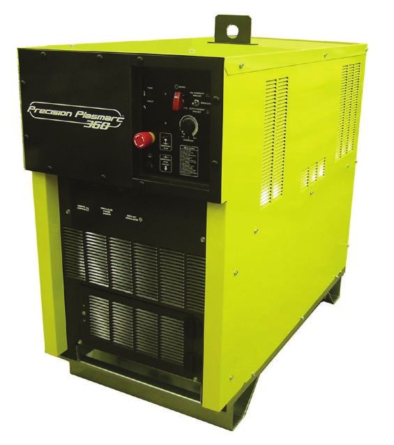
2.1 Introduction
The EPP power source is designed for marking and high speed plasma mechanized cutting applications. It can
be used with other ESAB products such as the PT-15, PT-19XLS, PT-600 and PT-36 torches along with the Smart
Flow II, a computerized gas regulation and switching system.
• 10 to 36 amperes for marking
• 30 to 360 amperes cutting current range
• Forced air cooled
• Solid state DC power
• Input voltage protection
• Local or remote front panel control
• Thermal switch protection for main transformer and power semiconductor components
• Top lifting eyes or base forklift clearance for transport
• Parallel supplemental power source capabilities to extend current output range.
2.2 General Specifications
EPP-360 460V, EPP-360 575V,
60Hz CSA, 60Hz
Part Number 0558006832 0558006833
Voltage 200 VDC
Current range DC (marking) 10A to 36A
Output
Current range DC (cutting) 30A to 360A
(100 % duty cycle)
Power 72 KW
* Open Circuit Voltage (OCV) 360 VDC
Voltage (3-phase) 460V 575V
Current (3- phase) 115A RMS 92A RMS
Frequency 60 HZ 60 HZ
Input KVA 91.6 KVA 91.6 KVA
Power 82.5 KW 82.5 KW
Power Factor 90.0 % 90.0 %
Input Fuse Rec. 150A 125A
17section 2 description
2.3 Dimensions and Weight
23.75” 47.25”
(603.25 mm) (1200 mm)
40.75”
(1035 mm)
Weight = 1085 lb
18section 3 installation
3.1 General
Failure To Follow Instructions Could Lead To Death, Injury
WARNING Or Damaged Property. Follow these instructions to pre-
vent injury or property damage. You must comply with lo-
cal, state and national electrical and safety codes.
3.2 Unpacking
• Inspect for transit damage immediately upon receipt.
• Remove all components from shipping container and check for loose parts in container.
• Inspect louvers for air obstructions.
3.3 Placement
• A minimum of 1 meter (3 ft.) clearance on front and back for cooling air flow.
• Plan for top panel and side panels having to be removed for maintenance, cleaning and inspection.
• Locate the EPP-360 relatively close to a properly fused electrical power supply.
• Keep area beneath power source clear for cooling air flow.
• Environment should be relatively free of dust, fumes and excessive heat. These factors will affect cool-
ing efficiency.
Conductive dust and dirt inside power source may cause arc flash-
caution over. Equipment damage may occur. Electrical shorting may occur if
dust is allowed to build-up inside power source.
See maintenance section.
19section 3 installation
3.4 Input Power Connection
Electric Shock Can Kill!
WARNING Provide maximum protection against electrical shock.
Before any connections are made inside the machine, open
the line wall disconnect switch to turn power off.
3.4.1 Primary Power
EPP-360 is a 3-phase unit. Input power must be provided from a line (wall) disconnect switch that contains fuses
or circuit breakers in accordance to local or state regulations.
Recommended input conductor and line fuse sizes:
Input at Rated Load Input and Ground Time delay
conductor* CU/ Fuse size
Volts Amperes mm2 (AWG) (amperes)
460 115 35 (2)* 150
575 92 35 (2)* 125
Rated load is output of 360A at 200V
* Sizes per National Electrical Code for a 90° C (194˚ F) rated copper conductors @ 40° C (104˚ F) ambient. Not
more than three conductors in raceway or cable. Local codes should be followed if they specify sizes other
than those listed above.
To estimate the input current for a wide range of output conditions, use the formula below.
(V arc) x (I arc) x 0.73
Input current =
(V line)
Dedicated power line may be necessary.
EPP-360 is equipped with line voltage compensation but to avoid
NOTICE impaired performance due to an overloaded circuit, a dedicated
power line may be required.
20section 3 installation
3.4.2 Input Conductors
• Customer supplied
• May consist either of heavy rubber covered copper conductors (three power and one ground) or run
in solid or flexible conduit.
• Sized according to the chart.
3.4.3 Input Connection Procedure
Improper Grounding Can Result In Death or Injury.
WARNING Chassis must be connected to an approved electrical
ground. Be sure ground lead is NOT connected to any pri-
mary terminal.
Chassis Ground Primary Terminals
Power Input Cable Access Opening (Rear Panel)
1. Remove small rear panel of the EPP-360.
2. Thread cables through the access opening in the rear panel.
3. Secure cables with strain relief at the access opening.
4. Connect the ground lead to the stud on the chassis.
5. Connect the power leads to the primary terminals.
6. Connect the input conductors to the line (wall) disconnect.
7. Before applying power, replace the rear cover panel.
21section 3 installation
3.5 Output Connections
Electric Shock Can Kill! Dangerous Voltage And Current!
Any time working around a plasma power source with cov-
ers removed:
WARNING • DISCONNECT POWER SOURCE AT THE LINE (WALL) DISCONNECT.
• HAVE A QUALIFIED PERSON CHECK THE OUTPUT BUS BARS (POSI-
TIVE AND NEGATIVE) WITH A VOLTMETER.
3.5.1 Output Cables (customer supplied)
Choose plasma cutting output cables (customer supplied) on the basis of one 4/0 AWG, 600 volt insulated cop-
per cable for each 400 amps of output current.
Note:
Do not use 100 volt insulated welding cable.
22section 3 installation
3.5.2 Output Connection Procedure
1. Open access panel on the lower front of the power source.
2. Thread output cables through the openings at the bottom of the power source immediately behind the front
panel.
3. Connect cables to designated terminals mounted inside the power source using UL listed pressure wire con-
nectors.
4. Close front access panel.
Front Access
Panel Closed
Front Access
Panel Opened
23section 3 installation
3.6 Parallel Installation
Two EPP-360 power sources may be connected together in parallel to extend the output current range.
3.6.1 Connections for Two EPP-360’s in Parallel
Note:
Primary power source has the electrode (-) conductor jumpered. The supplemental power
source has the work (+) jumpered.
1. Connect the negative (-) output cables to the arc starter box (high frequency generator).
2. Connect the positive (+) output cables to the workpiece.
3. Connect the positive (+) and negative (-) conductors between the power sources.
4. Connect the pilot arc cable to the pilot arc terminal in the primary power source. The pilot arc connection in
the supplemental power source is not used. The pilot arc circuit is not run in parallel.
5. Connect a power source paralleling control cable between the two power sources.
6. Connect the CNC control cable to the primary power source.
Connections for parallel installation of two EPP-360 power sources with both power sources in operation.
EPP-360 EPP-360
Supplemental Primary Power
Power Source Source
work electrode work electrode
(+) (-) (+) (-)
pilot arc
P/S Parallel Control Cable Control cable to water cooler
CNC
Control
Cable
1 - 14 AWG 600V
2 - 4/0 600V lead to pilot arc con- 2 - 4/0 600V
positive leads nection in arc starter negative leads
to workpiece box (h.f. generator) in arc starter box
(h.f. generator)
24section 3 installation
The EPP-360 does not have an ON/OFF switch. The main power is controlled through the line (wall) disconnect switch.
Do not operate the EPP-360 with Covers Removed. High
WARNING voltage components are exposed increasing shock haz-
ard. Internal components may be damaged because cool-
ing fans will lose efficiency.
Electric Shock Can Kill!
Exposed Electrical Conductors Can Be Hazardous!
Do not leave electrically “hot“ conductors exposed. When
disconnecting the supplemental power source from the
WARNING primary, verify the correct cables were disconnected. In-
sulate the disconnected ends.
When two power sources are connected in parallel and
one of the two is not powered, or if the paralleling cable
does not connect the two, the negative electrode conduc-
tor must be disconnected from the supplemental power
source and the plumbing box. Failure to do this will leave
the supplemental electrically “hot”, unsafe, as well as in-
operative.
Connections for parallel installation of two EPP-360 power sources with only one power source in operation.
EPP-360 EPP-360
Supplemental Primary Power
Power Source Source
work electrode work electrode
P/S Parallel Control
Control cable to
Cable
water cooler
Disconnect negative
connection from sec-
2 - 4/0 600V
ondary power source 2 - 4/0 600V
positive leads
and insulate to con- negative leads
to workpiece
vert from two to one in arc starter box
power source (h.f. generator)
25section 3 installation
3.6.2 Marking with Two Parallel EPP-360’s
Two EPP-360’s, connected in parallel, and can be used for marking down to 10A and cutting from 30A up to
720A.
OPERATION OF TWO PARALLEL EPP-360’S:
1. Provide start/stop, Cut/Mark, “HI CURRENT” logic signals and either logic or analog inputs to control the pilot
current signals to primary unit for both cutting and marking. When marking, both power sources are pow-
ered up, but the mark signal disables the output of the supplemental power source.
3.7 Interface Cable Connectors
E-Stop Connector
Remote Control (CNC)
Parallel Power Source
Coolant Circulator
26section 3 installation
3.7.1 CNC Interface Cables with Mating Power Source Connector and
Unterminated CNC Interface
GRN/YEL
RED #4
3.7.2 CNC Interface Cables with Mating Power Source Connectors at Both Ends
GRN/YEL
RED #4
27section 3 installation
3.7.3 Water Cooler Interface Cables with Mating Power Source Connectors at Both Ends
3.7.4 Power Source Parallel Control Cable
28section 4 operation
Dangerous Voltages and Current! Electric Shock Can Kill!
WARNING Before operation, ensure installation and grounding pro-
cedures have been followed. Do not operate this equip-
ment with covers removed.
4.1 EPP-360 Block Diagram
Control 1~
460V/575V 3 ~
Power Control
Input
Fuses Transformer
Soft
Main
Start
Contactor Relay / Interface
Relay
Board
3 x 2 Ohm
Main
300 Watt
Transformer
Resistors
3~ IGBT Driver
Rectifier Board
Main Control
Board CNC
Interface
2 x 6000uf &
4 x 400 Amp Isolation
450V
IGBT’s
Capacitors
Inductor
Front Panel
Output Display
29section 4 operation
4.2 Control Panel
E
F
B
A
C
D
H
J
30You can also read