Piper Archer Training Supplement - ATPFlightSchool.com
←
→
Page content transcription
If your browser does not render page correctly, please read the page content below
Piper Archer
Training Supplement

ATPFlightSchool.com   Revised 2021-07-15

IMPORTANT NOTICE
                   Refer to POH/AFM
                   Do not use procedures listed without referencing the full procedures
                   described in the approved Owner’s Manual, POH, or POH/AFM specific
                   to the airplane you are flying. Endurance and fuel capacities may vary
                   considerably depending on the specific model / serial number being flown
                   and any modifications it may have.

Copyright © 2021 Airline Transport Professionals.
The content of this manual is furnished for informational use only, and is subject to change without notice. Airline
Transport Professionals assumes no responsibility or liability for any errors or inaccuracies that may appear in this
manual. This manual does not replace the Piper Archer Pilot Operating Handbook, FAA Airplane Flying Handbook, or
Practical Test Standards / Airman Certification Standards. Nothing in this manual shall be interpreted as a substitute for
the exercise of sound judgement.
No part of this publication may be reproduced, stored in a retrieval system, or transmitted, in any form or by any means
electronic, mechanical or otherwise, without the prior written permission of Airline Transport Professionals.

To view recent changes to this supplement, visit:
atpflightschool.com/changes/supp-archer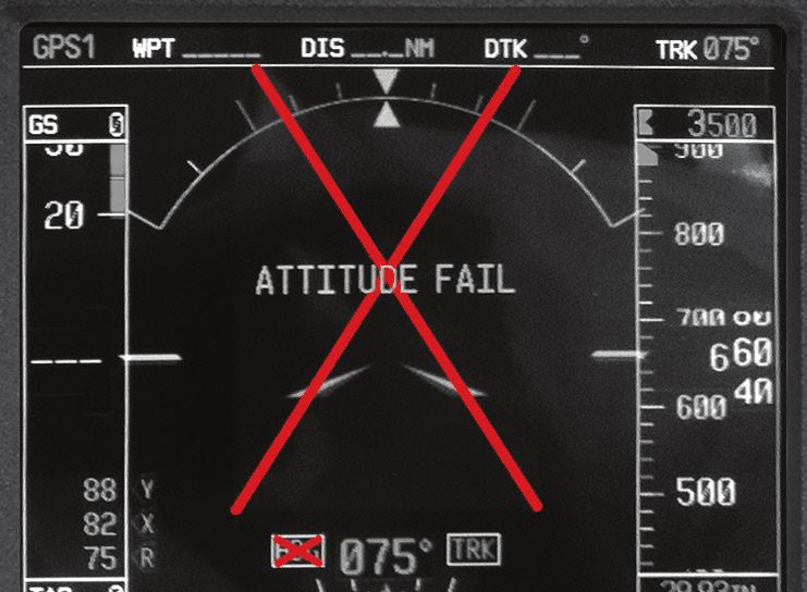
Revised 2021-07-15

                                                                Contents
Aircraft Systems........................................... 1                           Flap Setting........................................................ 39
  Engine................................................................... 1           Traffic Pattern Operations..................................40
  Oil.......................................................................... 2       Normal Visual Approach & Landing................... 41
  Propeller............................................................... 2            Short-Field Approach & Landing........................ 43
  Landing Gear........................................................ 2                Soft-Field Approach & Landing..........................44
  Brakes.................................................................. 2            Power-Off 180° Approach & Landing................ 45
  Flaps..................................................................... 3          Emergency Approach & Landing (Simulated).... 47
  Pitot Static............................................................ 3            Crosswind Approach & Landing.........................48
  Fuel System.......................................................... 3               Go-Around Procedure........................................50
  Electrical System.................................................. 4                 Rejected or Balked Landing...............................50
  Garmin G500........................................................ 6                 Precision Approach............................................ 51
  G500 Standby Instrumentation............................ 8                            Non-Precision Approach....................................52
  G500 Failures & Partial-Panel Approaches....... 10                                    Circling Approach...............................................54
  Garmin G1000..................................................... 13                  Holding...............................................................54
  Standard Avionics Configurations...................... 21                         In-Flight Maneuvers.................................55
  GPS Setup for VFR Airwork & Maneuvers..........25                                   Clean Configuration Flow.................................... 55
  List of Pilots Guides .......................................... 25                 Landing Configuration Flow............................... 55
  Heater................................................................. 25          Steep Turns........................................................ 56
  Stall Warning Horn.............................................. 26                 Maneuvering During Slow Flight........................56
Performance / Weight & Balance...........27                                           Power-Off Stall.................................................... 57
  Piper Archer V-Speeds....................................... 27                     Power-On Stall....................................................58
  Sample Weight & Balance Problem....................27                               Emergency Descent...........................................58
  Formulas............................................................. 28            Rectangular Course............................................59
  CG Envelope Graph............................................. 29                   S-Turns...............................................................60
                                                                                      Turns Around A Point......................................... 61
Departure Procedures..............................30
                                                                                      Chandelles.......................................................... 62
  Passenger Briefing............................................30
                                                                                      Lazy Eights......................................................... 63
  Pre-Takeoff Briefing...........................................30
                                                                                      Eights On Pylons................................................64
  Normal Takeoff................................................... 31
                                                                                      Steep Spirals...................................................... 65
  Short-Field Takeoff & Climb................................ 32
                                                                                      Accelerated Stall................................................. 65
  Soft-Field Takeoff & Climb.................................. 33
                                                                                      Secondary Stall (Power-On)...............................66
Arrival Procedures....................................34                              Secondary Stall (Power-Off)..............................66
  Piper Archer Landing Criteria............................34                         Elevator Trim Stall...............................................67
  Good Planning = Good Landing........................34                              Cross-Control Stall..............................................67
  Approach Briefing – Verbalize the Plan............ 35
                                                                                    Oral Review.................................................68
  Approach Briefing.............................................. 35
                                                                                      Sample Oral Questions.......................................68
  Announced Calls on Approach...........................36
  Stabilized Approach........................................... 36                 172 & Archer Differences.........................70
  Aiming Point ...................................................... 37
  Managing Energy .............................................. 37
  Pitch & Power .................................................... 37
  Go Around Philosophy........................................38
  Gust Factor ........................................................ 39
  Seat Position ..................................................... 39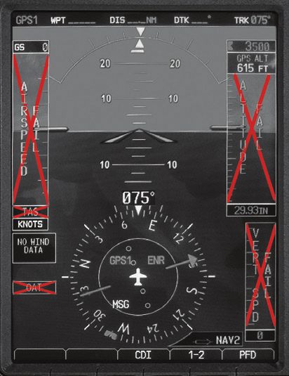
SECTION 1

                                              Aircraft Systems

Engine
The Archer is equipped with a Lycoming, 4-cylinder, O-360 (opposed, 360 cubic
inch) engine rated at 180 horsepower at 2700 RPM. The engine is direct drive
(crankshaft connected directly to the propeller), horizontally opposed (pistons
oppose each other), piston driven, carbureted and normally aspirated (no turbo
or supercharging). Engine ignition is provided through the use of two engine-
driven magnetos, which are independent of the aircraft's electrical system and
each other. Each magneto powers one spark plug per cylinder (for redundancy
and more complete combustion), for a total of 8 spark plugs.

                        L    Lycoming
                        H    Horizontally Opposed
                        A    Air Cooled
                        N    Normally Aspirated
                        D    Direct Drive

Carburetor Icing
Under certain atmospheric conditions at temperatures of 20° to 70° F
(-5° to 20° C), it is possible for ice to form in the induction system, even in
summer weather. This is due to the high air velocity through the carburetor
venturi and the absorption of heat from this air by vaporization of the fuel. To
avoid this, carburetor heat is provided to replace the heat lost by vaporization.
The initial signs of carburetor ice can include engine roughness and a drop in
RPM. Carburetor heat should be selected on full if carburetor ice is encountered.
Adjust mixture for maximum smoothness.

                    Partial carburetor heat may be worse than no heat at all, since it
                    may melt part of the ice, which will refreeze in the intake system.
                    Therefore when using carburetor heat, always use full heat
                    and when the ice is removed, return the control to the full cold
                    position.

                                                                  Aircraft Systems • 1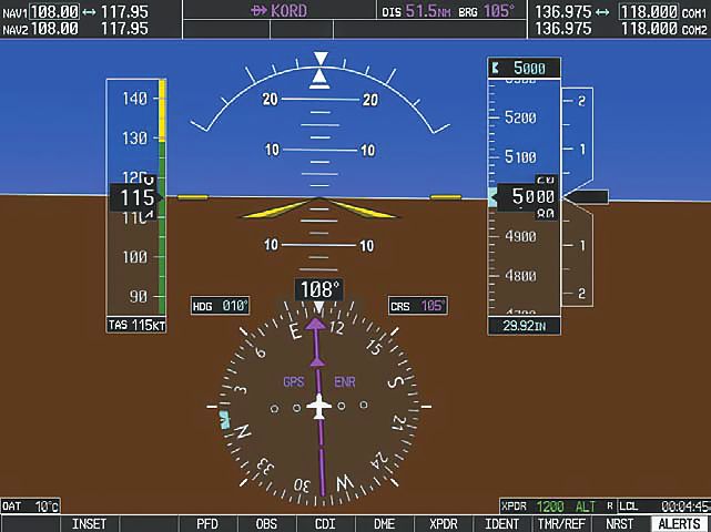
From the Archer POH, in regards to carburetor heat usage during approach:
      "Carburetor heat should not be applied unless there is an indication of carburetor
      icing, since the use of carburetor heat causes a reduction in power which may be
      critical in case of a go-around. Full throttle operation with carburetor heat on can
      cause detonation."

Oil
Acceptable range for oil in the Archer is 6.5–8 quarts. Never depart with the oil
indicating below 6 quarts.

                        ATP policy states any time a full quart of oil can be added to the
                        Archer oil system, a full quart should be added. Never add less
                        than a full quart; oil must only be added from full, unopened
                        containers, and any oil not poured into the engine must be
                        discarded.
                        Students are not permitted to add oil in ATP aircraft without
                        their instructor verifying the oil level and verbally agreeing to the
                        amount to be added.

Propeller
The Archer is equipped with a Sensenich two-bladed, fixed-pitch, metal
propeller. Propeller diameter is 76 inches. Maximum RPM (red line) is 2700 RPM.

Landing Gear
The landing gear is a fixed, tricycle-type gear, with oleo (air/oil) struts providing
shock absorption for all three wheels. The nose wheel contains a shimmy
dampener, which damps nose wheel vibrations during ground operations and
centers the nose wheel in the air. The nose wheel is linked to the rudder pedals
by a steering mechanism which turns the nosewheel up to 20° each side of
center.

Brakes
The Archer is equipped with hydraulically-actuated disc brakes on the main
landing gear wheels. Braking is accomplished by depressing the tops of the
rudder pedals. Both toe brakes and the parking brake have separate braking
cylinders, but share a hydraulic reservoir. The brake fluid reservoir is installed
on the top left front face of the firewall. To set the parking brake, pull back on
the brake lever, depressing the knob attached to the left side of the handle,
then release the brake lever. To disengage the parking brake, pull back on the
brake lever to disengage the catch mechanism, then allow the handle to swing
forward.

2 • Aircraft Systems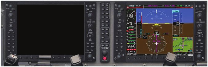
The parking brake is not to be used in training or flight checks
                     with ATP.

Flaps
The Archer is equipped with a manual flap system. The flaps are extended with
a lever located between the two pilot seats. Flap settings are 0°, 10°, 25°, and 40°,
and are spring-loaded to return to the 0 ° position.

                     ATP operations require flaps 25° for all landings except:
                       • Short and soft field, flaps 40°
                       • Precision approach, flaps 10°

Pitot Static
Pitot and static pressure are both received from a pitot head installed on the
bottom of the left wing. An alternate static source is located inside the cabin
under the left side of the instrument panel, for use in the event of static port
blockage. When using the alternate static source, the storm window and cabin
vents must be closed and the cabin heater and defroster must be on. This will
reduce the pressure differential between the cockpit and the atmosphere,
reducing pitot-static error. The pitot-static instruments are the airspeed
indicator, altimeter, and vertical speed indicator.
Both the pitot and static lines can be drained through separate drain valves
located on the left lower side of the fuselage interior.

Fuel System
The Archer, which uses 100 low lead avgas (blue), is equipped with two 25
gallon fuel tanks. One gallon is unusable in each tank. There is one engine-
driven and one electrically-driven fuel pump. The electric fuel pump is used for
all takeoffs and landings, and when switching tanks.

                     ATP uses the electric fuel pump for in-flight maneuvers, except
                     for steep turns.

The aircraft is equipped with a three-position fuel selector control. The positions
are “L”, “R”, and “OFF”.
The correct procedure for switching tanks in cruise flight is:
    1.   Electric fuel pump on
    2. Fuel selector from “L” to “R” or from “R” to “L”
    3. Check fuel pressure

                                                                   Aircraft Systems • 3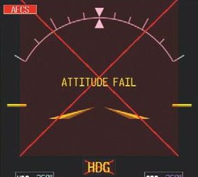
4. Electric fuel pump off
    5. Check fuel pressure
An electric engine priming system is provided to facilitate starting. The primer
switch is located on the far left side of the overhead switch panel.

                       CAUTION: DO NOT OVER-PRIME. Over-priming washes lubrication
                       from cylinder walls and increases fire risk. Always follow the
                       checklist for primer usage.

Fuel Management
Throughout operation, checklists will call for "Fuel Selector... Proper Tank." It is
important to monitor fuel burn to maintain a balanced fuel load. The Archer
POH does not provide a limitation on fuel imbalance. It is ATP's policy that
the fuel selector should not be changed during critical phases of flight, to
include takeoff and operations below pattern altitude, unless called for on an
emergency checklist.
During cruise flight and maneuvers, fuel load should be monitored and the fuel
selector should be selected to the fullest tank only when a noticeable difference
in fuel load occurs. 30 minutes of operation should result in a fuel load
difference of several gallons, and is a good guideline for fuel selector changes.
During pattern work operations, the fuel selector should only be changed while
on the ground during a Full Stop/Taxi Back procedure. It is critical to follow the
proper procedure for changing fuel tanks while on the ground, as well as while
in flight. Failure to follow the proper fuel selector change procedure can lead to
interruption in fuel flow, and engine failure, during a critical phase of flight.

Electrical System
The Archer is equipped with a 28-volt DC electrical system and a 24-volt lead-
acid main battery. (Archers with Garmin G1000 avionics also have an isolated
24-volt emergency battery.) Electrical power is supplied by a 70-amp, engine-
driven alternator. A voltage regulator maintains a constant 28-volt output from
the alternator. An overvoltage relay is located on the forward left side of the
fuselage behind the instrument panel. In aircraft equipped with Garmin G500
avionics, alternator output is displayed on a digital ammeter on the instrument
panel. For Archers with G1000 avionics, electrical system parameters may be
viewed on the Engine Indication System display on the MFD.

4 • Aircraft Systems
All Aircraft
The main battery is used as a source of emergency electrical power and for
engine starts. High drain items include the lights, vent fan, heater, radios, and
PFD/MFD. If an electrical problem arises, always check circuit breakers. If a circuit
breaker is popped, reset only one time.
CAUTION: Do not reset popped circuit breakers if smoke can be
smelled.
Other electrical components include the standby attitude indicator (G500) or
standby instrument (G1000), the starter, the electric fuel pump, electric engine
primer, the stall warning horn, the ammeter (G500), and the annunciator panel
(G500).
Alternator Failure - G500 Aircraft
In the case of the "ALTERNATOR INOP" annunciator, follow the "ALT Annunciator
Illuminated" checklist. The expanded procedure can be found in the Archer POH
Section 3.25:
"Loss of alternator output is detected through zero reading on the ammeter. Before
executing the following procedure, ensure that the reading is zero and not merely
low by actuating an electrically powered device, such as the landing light. If no
increase in the ammeter reading is noted, alternator failure can be assumed. The
electrical load should be reduced as much as possible. Check the alternator circuit
breakers for a popped circuit.
The next step is to attempt to reset the overvoltage relay. This is accomplished by
moving the ALT switch to OFF for one second and then to ON. If the trouble was
caused by a momentary overvoltage condition (30.5 volts and up) this procedure
should return the ammeter to a normal reading.
Note: Low Bus Voltage Annunciator will be illuminated.
If the ammeter continues to indicate "0" output, or if the alternator will not remain
reset, turn off the ALT switch, maintain minimum electrical load, and land as soon
as practical. Anticipate complete electrical failure. Duration of battery power will be
dependent on electrical load and battery condition prior to failure."
Once the battery is exhausted and complete electrical failure occurs, the G500
system will be rendered inoperative. In this situation, limited flight instrument
information is available from the standby instrumentation (see page 8 for
more information).
Aircraft Systems • 5Alternator Failure - G1000 Aircraft
In the case of a red ALTR FAIL CAS message, follow the "Alternator Failure"
checklist. The expanded procedure can be found in section 3.5d of the Archer
POH. Following this checklist will attempt to reset the alternator; if this is
unsuccessful, the aircraft's main battery will continue to provide power to the
Essential Bus (see POH for details on equipment powered by this bus).
If the main battery can no longer provide adequate power, and the EMERG BATT
switch is in the ARM position, the emergency battery will automatically begin
providing power to the emergency bus. This is indicated by a black EMERG
BATT ON CAS message. If this occurs, follow the "Complete Electrical Failure"
checklist. The emergency battery will provide approximately 30 minutes of
power to the PFD, COM/NAV 1, standby flight instrument, audio panel, and
engine instruments. Land as soon as possible.
Once the emergency battery is exhausted, the G1000 system will be rendered
inoperative. In this situation, limited flight instrument information is available
from the standby instrumentation (see page 17 for more information).
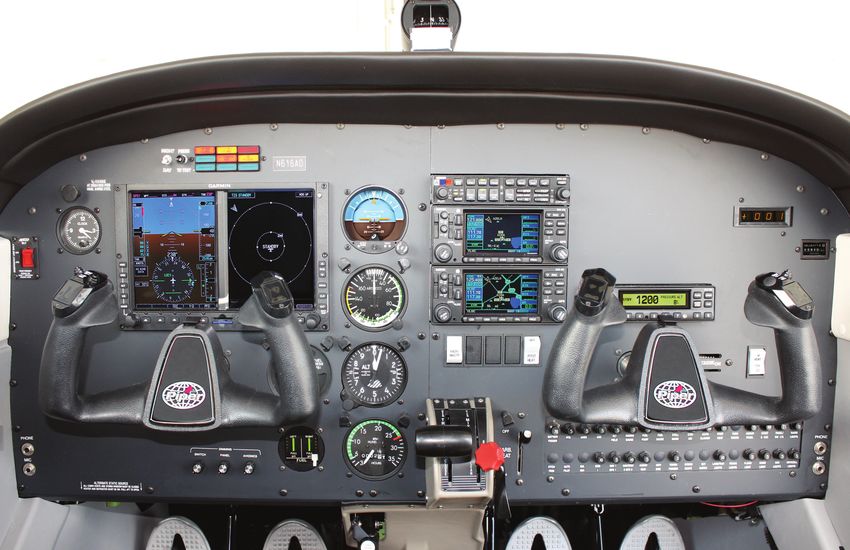
Garmin G500
Some ATP Archers are equipped with the Garmin G500 electronic flight deck.
The G500 powers on with the battery master switch.
G500 Components
The G500 is comprised of six main components:
• Primary Flight Display (PFD, left) and
Multi-Function Display (MFD, right)
• Attitude Heading Reference System (AHRS)
• Air Data Computer (ADC)
• Magnetometer
• Temperature Probe
• Dual Garmin GNS 430 GPS
The PFD (left) shows primary flight information in place of traditional pitot-
static and gyroscopic instruments, and also provides an HSI for navigation. ATP
procedures call for configuring the MFD (right) to display traffic information.
The Attitude Heading Reference System (AHRS) contains tilt sensors,
accelerometers, and rate sensors to provide attitude and heading information
on the PFD.
The Air Data Computer (ADC) compiles information from the pitot-static system
and an outside air temperature sensor to provide pressure altitude, airspeed,
vertical speed, and outside air temperature on the PFD.
6 • Aircraft SystemsThe magnetometer senses the earth's magnetic field and sends data to the
AHRS for processing to determine magnetic heading.
The temperature probe provides outside air temperature (OAT) data to the ADC.
The dual Garmin GNS 430 GPSs provide input to the AHRS and PFD/MFD.
CAUTION: The GNS 430 and G500 units each have their own
databases. Navigation, terrain and map information on the G500
Multi-Function Display (MFD) may not be current and is not to be
used for navigation. Use the G500 MFD for traffic information.
G500 PFD Functions
These buttons toggle the function of the PFD knob.
Set heading bug - HDG
(push PFD knob to set heading bug to current heading)
Set course - CRS
(when in VLOC mode)
Set altitude bug and alerter - ALT
Set V/S Bug - V/S
(do not use)
Altimeter setting - BARO
CDI needle color indicates NAV source: green for VLOC /
magenta for GPS.
G500 equipped Archers do not have a conventional turn coordinator. A slip-
skid indicator is located at the top of the attitude indicator. Step on the “brick”
instead of the “ball”. Use the reference lines and the magenta line that appears
above the heading indicator to identify a standard rate or half-standard rate
turn.
Outside air temperature (OAT) displays on the PFD under the airspeed tape.
Ground track can be identified on the heading indicator by a small magenta
diamond near the lubber line (only visible when ground track is different than
heading).
Aircraft Systems • 7The digital altitude and airspeed readouts are very sensitive and can cause
some pilots to continuously make corrections for insignificant deviations. Do
not overcorrect for deviations of a few feet. Crosscheck digital and analog
standby instruments to avoid the tendency to overcorrect.
Refer to the complete G500 Pilot's Guide in the ATP Library, or in
ForeFlight Documents.
G500 Standby Instrumentation
Because the G500 is electrically powered, electrical system failures (particularly
alternator failures) risk leaving the pilot without critical flight instrument
information. If an alternator failure or other electrical malfunction occurs while
in instrument conditions, the pilot must immediately work to safely exit IMC
and proceed to a landing under visual conditions. The Archer’s main battery
will continue to power the G500 for a limited time, which can be extended by
proper electrical load reduction. However, if the alternator malfunctions (and
operation is not restored by completion of the appropriate checklist), assume
that the G500 could cease operation at any point.
The Archer is equipped with limited standby instrumentation, in case the G500
stops operating while the pilot is still in IMC. This includes:
• An electrically-powered gyroscopic standby attitude indicator with an
internal battery backup
• A conventional standby altimeter and standby airspeed indicator,
connected to the pitot-static system
• A magnetic compass for heading reference
Standby Attitude Indicator Operation
During normal operations, the standby attitude indicator is powered and the
internal battery is charged by the aircraft’s electrical system. An alternator
failure will have no immediate effect on the standby attitude indicator, which
will continue to draw power from the aircraft’s main battery. Once the main
battery is eventually depleted and power to the standby attitude indicator is
interrupted, it will automatically switch over to its internal battery and continue
operation for approximately 60 seconds. During this time, an amber status LED
will blink next to the STBY PWR button to alert the pilot that action is required.
Press and release the STBY PWR button once to continue operation of the
standby attitude indicator.
8 • Aircraft SystemsFollowing an alternator failure, the standby attitude indicator
cannot switch to its internal battery until power from the main
battery is interrupted, which may take 30 minutes or more. Do
not press the STBY PWR button immediately. Keep the status
LED in your scan, and press and release the button once it begins
to blink. Do not press and hold the STBY button more than 4
seconds or the standby attitude indicator will revert to test
mode.
If the STBY PWR button is not pressed while the amber LED is flashing, the unit
will shut down and a red gyro warning flag will appear. At this point, the pilot
can still press and release the STBY PWR button to activate the internal battery
and resume use of the standby attitude indicator. However, it will take some
time for the gyroscope to spin up and provide accurate attitude reference.
When fully charged, the internal battery should provide up to 1 hour of
operation; however, a situation requiring use of the standby attitude indicator is
an emergency. Exit IMC and land as soon as possible. Once the internal battery
is depleted, the red gyro warning flag will appear.
Standby Attitude Indicator Battery Check
Prior to flight, the standby attitude indicator’s internal battery must be tested.
To accomplish the test, aircraft electrical power must be on (Battery Master
ON) and the standby attitude indicator gyro must be fully operational with the
red gyro flag out of view. Test the standby battery as called for by the Run Up
Checklist:
• Press and hold the STBY PWR button for approximately four seconds.
This puts the gyro in a one-minute battery test mode. The amber status
LED will flash during the test sequence.
• A continuous green light illuminated beneath “TEST” during the full
sequence indicates that the standby battery is good.
• A red light illuminated anytime during the test indicates that the
battery is not charged and may require replacement. Contact
maintenance.
Do not press and hold the STBY PWR button during flight. This
would put the unit into the test mode. Except when testing
the battery during run-up, press the button once and promptly
release it.
Aircraft Systems • 9Standby Attitude Indicator Shutdown
During a normal aircraft shutdown using the Shutdown Terminate checklist,
the status LED will begin to blink once the battery master is turned off. When
this occurs, do not press the STBY PWR button. Allow the LED to blink for
approximately 60 seconds, at which point the red gyro warning flag will appear
to indicate that the unit has powered down.
If the STBY PWR button is inadvertently pressed during aircraft shutdown, this
will activate emergency operation and deplete the internal battery. To correct
this, press the button again to deactivate the standby attitude indicator.
G500 Failures & Partial-Panel Approaches
For partial-panel training and checkrides, the two most common training
scenarios are simulated AHRS failure and PFD failures.
Instrument
Failure Condition Simulated By Approaches Available
AHRS Failure Cover Attitude Indicator All precision and non-
(ADI) precision
PFD Failure Dim PFD/MFD screens Only GPS approach
Electrical Failure No simulated failure None
available
ADC Failure No simulated failure All precision and non-
available precision
Circuit breaker-simulated failures are prohibited in ATP aircraft.
Piper and Garmin advise against pulling circuit breakers as a
means of simulating failures on the Garmin G500 system. Pulling
circuit breakers, or using them as switches, has the potential to
weaken the circuit breaker to a point at which it may not perform
its intended function. Also reference Advisory Circulars 120-80,
23-17B, and 43.13-1B.
10 • Aircraft SystemsAttitude & Heading Reference System (AHRS) Failure
Indications:
1. The sky/ground presentation is removed.
2. A red X appears across the Attitude Direction Indicator (ADI).
3. Yellow “ATTITUDE FAIL” and “HDG” alert messages appear on the PFD.
4. A “TRK” message appears to the right of the ground track at the top of
the compass rose.
5. Rate-of-turn information is unavailable.
6. “HDG LOST”, “HDG FAULT”, and "TRK TRAFFIC” alert messages appear
on the MFD.
AHRS Failure
The PFD continues displaying airspeed, altitude, vertical speed, compass rose
and ground track. Ground track and compass rose indications are supplied by
GPS, indicated by a “TRK” message. Any precision or non-precision approach is
available using the HSI on the PFD.
Pilot Action
1. Use standby attitude indicator.
2. Continue using HSI on PFD. Verify track against magnetic compass
heading.
3. Precision (ILS) and non-precision (GPS, localizer, and VOR) approaches
can be accomplished.
PFD Failure
Indications
1. PFD screen is dark.
Aircraft Systems • 11Pilot Action
1. Refer to the standby instruments.
2. Use the GPS CDI page for navigation and approaches.
CLR - Press and hold for 3 seconds to return to default CDI page
3. Only GPS non-precision approaches can be accomplished.
During an MFD failure, with the PFD functioning normally, all
approaches are available for use.
Electrical Failure
Indication
1. The G500 and GPS systems will be inoperative/dark.
2. The “STBY PWR” button on the standby attitude indicator will begin
blinking.
Pilot Action
1. Use standby attitude indicator. Press the "STBY PWR" button right of
the blinking LED to continue operating using its internal battery.
2. Use standby airspeed, altimeter, and compass.
3. Declare an emergency and exit IMC as soon as practicable. The
manufacturer does not specify the endurance time of the integral
emergency battery.
Air Data Computer (ADC) Failure
Indications
1. Loss of data accompanied by a red X and yellow alert messages occurs
over:
• Airspeed
• Altitude
• Vertical speed
• True airspeed (TAS)
• Outside air temperature (OAT)
2. Wind calculations are unavailable
12 • Aircraft SystemsAttitude and heading references will function normally on the PFD.
ADC Failure
Pilot Action
1. Use standby airspeed indicator and altimeter.
There is no backup for the VSI, but known pitch attitudes using
the attitude indicator, power settings, and airspeeds produce
consistent rates.
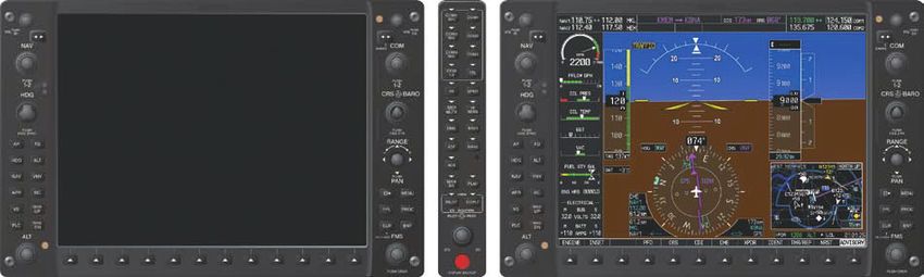
Garmin G1000
Some Piper Archers are equipped with the Garmin G1000 electronic flight deck.
G1000 Components
The G1000 is comprised of several main components, called Line Replaceable
Units (LRUs):
• Primary Flight Display (PFD)
• Multi Function Display (MFD)
• Integrated Avionics Units (2)
• Air Data, Attitude and Heading Reference System (ADAHRS)
• Engine/Airframe Unit
• Magnetometer
• Audio Panel
• Transponder
The PFD (left screen) shows primary flight information in place of traditional
pitot-static and gyroscopic instruments, and also provides an HSI for navigation.
Aircraft Systems • 13The MFD (right screen) provides a GPS-enabled moving map with traffic and weather information. It can also be used to display waypoint/airport information, flight plans, instrument procedures, trip planning utilities, and system setup/configuration information. The Integrated Avionics Units each contain a WAAS-enabled GPS receiver, a VHF nav/comm radio, and a flight director. They also serve as communications hubs to relay information from the other LRUs to the PFD and MFD. For redundancy, one IAU is connected to each display, and they do not communicate with each other directly. The Air Data, Attitude and Heading Reference System uses accelerometers and rate sensors, along with magnetic field readings from the magnetometer and GPS information from the IAUs, to provide aircraft attitude and heading information to the flight displays and IAUs. It also processes data from the pitot/ static system as well as the OAT probe to provide pressure altitude, airspeed, vertical speed, and air temperature data to the system. The Engine/Airframe Unit receives and processes signals from the engine and airframe sensors (engine RPM and temperatures, fuel quantity, etc.). The magnetometer measures the local magnetic field and sends data to the AHRS to determine the aircraft’s magnetic heading. The audio panel is installed between the two display screens and integrates controls for the nav/com audio, intercom system, and marker beacon receiver. It also controls manual display reversionary mode (which can shift the primary flight instruments to the MFD). The transponder is a Mode S device, controlled via the PFD, that also provides ADS-B In/Out capability. 14 • Aircraft Systems
G1000 Flight Instruments

                                 Primary Flight Display (Default)

           Airspeed Indicator                                  Altimeter
           Turn Rate Indicator                                 Slip/Skid Indicator
           Horizontal Situation Indicator (HSI)                Attitude Indicator
           Vertical Speed Indicator (VSI)

The G1000 PFD displays the same flight information as the conventional “six-
pack”, but pilots should be aware of the following considerations.
Airspeed and altitude information are displayed with moving tapes and a
digital readout of the current airspeed and altitude to the nearest knot / 20
feet, respectively. This precision leads some pilots to overcontrol the aircraft,
continuously making corrections for insignificant deviations. Be sure not to
overcorrect for deviations of a few feet or knots.
The information traditionally displayed on the turn coordinator is split between
two locations on the screen. The inclinometer (“ball”) is replaced with a white
“brick” under the pointer at the top of the attitude indicator. “Step on the
brick” to center it and maintain coordinated flight. The rate of turn indication
is provided by a magenta trend vector at the top of the HSI. Tick marks are
provided for half-standard and standard rate turns.
On the HSI, a small magenta diamond indicates the aircraft’s current ground
track. (This diamond may not be visible if crosswinds are minimal and the track
is nearly equal to the heading.) Also, pilots should note the color of the CDI
needle to determine the current navigation source. Magenta needles indicate
GPS, while green needles indicate VOR or LOC.

                                                                           Aircraft Systems • 15
G1000 Controls
The G1000 has duplicate sets of controls on the PFD and MFD bezels. Using the
controls towards the center of the aircraft (on the right side of the PFD and the
left side of the MFD) helps to ensure that both student and instructor can see
each other’s inputs.
PFD/MFD Controls
Left Side - Top to Bottom
NAV Radio Controls: Use the NAV knob, along with the frequency
transfer key, to tune NAV receiver frequencies. Turn the VOL knob
to control the volume, and press the knob to toggle the Morse code
identifier on/off.
HDG Knob: Sets the heading bug on the HSI.
AFCS Keys: Used to program the Garmin GFC 700 Automatic Flight
Control System. (Not installed on all aircraft.)
ALT Knob: Sets the altitude bug on the altimeter.
Right Side - Top to Bottom
COM Radio Controls: Use the COM knob, along with the frequency
transfer key, to tune COM receiver frequencies. Turn the VOL knob to
control the volume, or press to turn the automatic squelch on or off.
CRS/BARO Knobs: Turn the outer, large knob to set the barometric
pressure setting for the altimeter. Turn the small, inner knob to select a
course on the HSI when in VOR or OBS mode.
16 • Aircraft SystemsRANGE Joystick: Turn to adjust map range. Press to activate the map
pointer.
FMS Keys/Knob: Use these to program flight plans, enter waypoints,
select instrument procedures, etc.
Bottom Edge
Softkeys: There are 12 softkeys along the bottom edge of each display
with functions that vary depending on context.
Review the G1000 Pilot’s Guide for your airplane for more
information on the G1000’s features. These are available in the
ATP Library and in ForeFlight Documents.
Standby Instruments
G1000-equipped Piper Archers are also equipped with a standby flight
instrument (either an Aspen Evolution Backup Display or a Garmin G5) mounted
on the left side of the instrument panel. Both Garmin and Aspen units are fully
digital, independent flight instrument displays providing attitude, barometric
altitude, airspeed, heading, vertical speed, slip/skid, and turn rate indications.
Should the G1000 fail (say, due to a failed display screen or ADAHRS), the pilot
can control the aircraft using the standby instrument. If this occurs, exit and
avoid IFR conditions as soon as practical.
G1000-equipped Archers do not have traditional magnetic
compasses. Instead, the standby instruments provide a backup
source of magnetic heading information. The Aspen EBD
contains an internal magnetometer, while the Garmin G5 is
accompanied by an external GMU 11 magnetometer unit.
The standby instrument can draw electrical power from a few different sources,
to ensure the pilot has uninterrupted access to critical flight information:
• In normal operation, the standby instrument is powered by the engine-
driven alternator via the Essential Bus.
• If the alternator fails, the primary battery will continue to power the
standby instrument via the Essential Bus.
• Once the primary battery is depleted (or if the primary electrical system
otherwise fails), the Archer’s emergency battery will power the standby
instrument via the Emergency Bus for at least 30 minutes in the case of
the Aspen EBD, or up to 4 hours in the case of the Garmin G5.
Aircraft Systems • 17• If all electrical power to the standby instrument is removed, a backup
internal battery in the unit will continue to power it for approximately
30 minutes.
Prior to flight, the pilot must check the power level of the emergency battery
using the procedures in the ATP Archer Checklists. With the alternator and
battery master off, move the emergency battery switch to the ARM position.
The PFD and standby instrument should both power on with all instrument
indications functional, and the E VOLTS reading on the PFD must be at least 23.3
volts. If E VOLTS is low prior to engine start, check again following run up.
Activation of the emergency battery following electrical failure indicates an
emergency situation. Land as soon as possible.
The standby instrument will not automatically switch to its
internal battery if the aircraft is on the ground (inferred from low
airspeed). This ensures the unit does not remain on after aircraft
shutdown. However, if the Aspen EBD does not automatically
turn off during aircraft shutdown, press and hold the red
REV button on the upper right for up to 20 seconds until the
“Shutdown in progress” message appears. The Garmin G5 can
be turned off by pressing and holding the power button for five
seconds.
G1000 Failures & Partial-Panel Approaches
Training Considerations
For partial-panel training and checkrides, the two most common training
scenarios are PFD failures and ADAHRS failures.
• PFD Failure: Simulate by dimming the PFD screen. The student
should respond by pushing the DISPLAY BACKUP button to activate
reversionary mode and move the flight instrument displays to the
MFD. All instrument procedures remain available. Use the Inset Map for
situational awareness.
• ADAHRS Failure: The ADAHRS has various failure modes that can cause
one or more instrument indications to become unavailable. To simulate
a worst-case scenario in which all of the G1000’s flight instruments are
unusable, dim the PFD screen and do not activate reversionary mode.
Then, fly the airplane using the standby instruments. The MFD should
remain on the moving map screen for situational awareness. GPS
approach procedures remain available. Set the MFD fields to TRK, DTK,
XTK, and DIS to maintain situational awareness of your position relative
to the intended track (in lieu of the CDI).
18 • Aircraft SystemsOther failure modes in which some (but not all) instruments are unavailable can
be simulated using paper or foam cutouts that hang from the COM and NAV
knobs and cover up particular areas of the PFD screen. ATP does not provide
these cutouts.
The simulation of failures by pulling circuit breakers is prohibited
in ATP aircraft. Piper, Garmin, and the FAA all advise against
pulling circuit breakers as a means of simulating failures on the
G1000 system. Pulling circuit breakers, or using them as switches,
has the potential to weaken the circuit breaker to a point at
which it may not perform its intended function.
LRU Failures
If an LRU or an LRU function fails, a red or amber X is displayed over the
window(s) corresponding to the failed data. If this occurs, follow the appropriate
emergency checklist. Generally, this involves checking the circuit breaker for the
affected LRU, then (if the problem is not fixed by resetting the breaker) using
the standby instruments to exit IFR conditions and land as soon as practical.
AHRS Failure ADC Failure
AHRS Modes
The AHRS uses GPS, magnetometer, and air data to assist in attitude/heading
calculations, in addition to the data from its internal sensors. Loss of this
external data can affect the availability of attitude and heading information,
even if the AHRS itself is functional. Either GPS or air data must be available for
the AHRS to provide attitude information. Additionally, loss of magnetometer
data will result in invalid heading information.
If the AHRS cannot provide valid heading information, the course
pointer on the HSI will point straight up, effectively converting
it into a standard, fixed-card course deviation indicator. As a
result, pilots can still perform partial-panel instrument approach
procedures following an AHRS failure. Cross-reference between
heading information from the magnetic compass and course
information from the PFD.
Aircraft Systems • 19Display Failures
If either display fails, the G1000 should automatically enter reversionary mode,
in which important flight information is presented in a condensed format on
the remaining display(s). Reversionary mode can also be activated manually by
pressing the red DISPLAY BACKUP button on the audio panel. Engine Indication
System readings appear on the left edge of the screen, and the inset map
appears at lower right.
Reversionary Mode (Failed PFD)
Because the IAUs are not cross-linked, any functions handled by just one IAU will
be lost if its corresponding display fails. If the PFD fails, NAV1, COM1, and GPS1
will be unavailable. If the MFD fails, NAV2, COM2, and GPS2 are unavailable.
Other optional avionics may also become unavailable, depending on the
particular avionics configuration.
Electrical Failure
If the alternator fails, a red “ALTR FAIL” CAS warning message will appear on the
PFD. All G1000 equipment will initially remain on, powered by the main battery.
Follow the appropriate emergency checklist to verify the failure and attempt to
reset the alternator.
If the alternator is still failed, continue to the electrical load shedding portion of
the checklist. Part of this procedure is to turn off the avionics master. This will
disable the MFD and #2 IAU, along with optional avionics. The PFD will remain
active and switch to reversionary mode.
Once the main battery is depleted, the emergency battery will activate and
provide approximately 30 minutes of power to the emergency bus. This will
maintain power to the PFD, but the transponder and the cooling fans will shut
off. Declare an emergency, exit IMC, and land as soon as possible.
20 • Aircraft SystemsStandard Avionics Configurations
Garmin G1000
Taxiing
MFD: Map page with range set to airport diagram view.
Airport diagram may be expired, reference for situational
awareness only.
Traffic Pattern Operations
PFD: Traffic map (INSET left).
MFD: Mag page with minimum range set for situational and traffic
awareness. DCLTR (declutter) set to DCLTR-1.
Enroute
PFD: Active with appropriate nav source (needles) active.
MFD: Map page with Traffic Information active. Traffic inset should be
included on the PFD for added traffic awareness. DCLTR (declutter) set to
DCLTR-1.
Full Panel Approaches
PFD: Active NAV source on HSI/Traffic map (INSET left).
MFD: Map page with traffic information active and orientation set to track
up. DCLTR (declutter) is set to DCLTR-1.
Aircraft Systems • 21G1000 Standard Configuration
Partial Panel Approaches
PFD: Dimmed.
MFD: Reversionary Mode.
Map Overlay: On with Traffic Information active.
G1000 Partial Panel Configuration
22 • Aircraft SystemsGarmin G500 w/ Dual GNS430
VFR & Traffic Pattern Operations
MFD: Map page group, traffic map page (map page 4), scrolled in to view
airport diagram or minimum range set with Traffic Overlay.
Map terrain data is not kept up to date in G500 equipped aircraft.
Verify DCLTR (declutter) is set to DCLTR-1.
COM/NAV 1: Nav page group, Moving map page (Nav page 2).
COM/NAV 2: Nav page group, Traffic information page (Nav page 3).
Dual Garmin GNS 430 GPS Configuration
Enroute and Full Panel Approaches
PFD: Active with appropriate nav source active on HSI.
MFD: Map page group, traffic Map page (Map page 4).
COM/NAV 1: Default Nav page (Nav page 1).
VLOC Button: Selected to appropriate nav source.
COM/NAV 2: Moving Map page (Nav page 2), orientation set to TRACK UP.
Aircraft Systems • 23G500 w/ dual 430s - Enroute
Partial Panel Approaches:
PFD: Dimmed or covered. Use standby instruments.
MFD: If not dimmed, map page with traffic information active and
orientation set to track up.
COM/NAV 1: Approach loaded, Default Nav page (Nav 1).
Default Nav page values: DIS, GS, DTK, TRK, XTK, ETE
COM/NAV 2: Nav page group, Moving map page (Nav page 2), orientation
set to TRACK UP.
VLOC Button: Selected to appropriate nav source.
Course Guidance: TRK information (on GPS1).
24 • Aircraft SystemsGPS Approach with No HSI: Use GPS1 set to CDI page GPS2 Set to Moving Map Page (Nav 2)
For PFD failures on the G500, the only approach option is a GPS
approach, using the GPS CDI for course guidance.
GPS Setup for VFR Airwork & Maneuvers
When in a familiar area performing VFR maneuver training, or when remaining
in the traffic pattern for takeoff/landing practice, at least one GPS unit should be
selected to the Traffic page. If two units are present, one may be selected to the
Moving Map page. To avoid redundant information, never have two systems on
the same page.
Aircraft maneuvering will cause errors in the display. These errors primarily
affect relative bearing information and traffic target track vector (it will lag).
Traffic information is provided as an aid in visually acquiring traffic. It is the
responsibility of the pilot to see and maneuver to avoid traffic.
List of Pilots Guides
Aspen Evolution Backup Display Pilot’s Guide
Archer G1000 NXi Pilot’s Guide
Garmin G5 Standby Instrument’s Pilot Guide
G500 Pilot’s Guide
GNS430 Pilot's Guide
Heater
Heat for the cabin interior and the defroster system is provided by a heater
shroud that routes fresh air past the exhaust manifold and directs it into the
cabin. The amount of heat desired can be regulated with the controls located
on the far right side of the instrument panel.
CAUTION: When cabin heat is operated, the heat duct surface
becomes hot. This could result in burns if arms or legs are placed
too close to heat duct outlets or surface.
Aircraft Systems • 25Stall Warning Horn
The Archer is equipped with an electric stall detector located on the leading
edge of the left wing. The stall warning horn is activated between 5 and 10
knots above stall speed. In G500 Archers, the horn emits a continuous sound. In
G1000 Archers, the warning is an aural annunciation ("Stall... Stall... Stall...").
Additional aircraft systems information can be found in Section
7 of the Piper Archer Pilot's Operating Handbook, available in
the ATP Training Library and ForeFlight Documents. ATP training
videos reviewing this material are available on the Ground
School Support Videos page.
26 • Aircraft SystemsSECTION 2
Performance / Weight & Balance
Piper Archer V-Speeds
Speeds listed below are in Knots Indicated Airspeed (KIAS).
Airspeed
V-Speed KIAS Description Indicator Marking
VSO 45 Stall speed in landing configuration Bottom of White Line
VS 50 Stall speed with zero flaps Bottom of Green Line
VR 60 Rotation speed (start rotation)
VX 64 Best angle of climb
VY 76 Best rate of climb
VG 76 Best glide speed at max weight
VFE 102 Maximum flap extension speed Top of White Line
VNO 125 Max Structural Cruising Speed Top of Green Line
VNE 154 Never exceed speed Red Line
VA 113 Maneuvering speed at 2,550 pounds
VA 89 Maneuvering speed at 1,634 pounds
Maximum demonstrated crosswind 17 knots
Sample Weight & Balance Problem
Complete the following sample weight and balance problem.
Conditions
Basic Empty Weight................................................................................. 1590.0 lbs.
(Remember to use actual aircraft BEW for flight check.)
Front Pilots.........................................................................................................350 lbs.
Rear Passengers.................................................................................................. 50 lbs.
Performance / Weight & Balance • 27Baggage............................................................................................. 2 Bags @ 75 lbs.
(May need to relocate some baggage to rear passenger seats.)
Max Ramp Weight....................................................................................... 2,558 lbs.
Max Takeoff/Landing Weight.................................................................. 2,550 lbs.
Max Baggage Weight.....................................................................................200 lbs.
Max Usable Fuel.................................................................................................48 gal.
Fuel Burn...............................................................................................................20 gal.
Weight × Arm = Moment
Basic Empty Weight 87.50
Front Pilots + 80.50 +
Rear Passengers + 118.10 +
Baggage 200 lbs. Max + 142.80 +
Zero Fuel Weight = CG =
CG = Moment / Weight
Usable Fuel + 95.00 +
Ramp Weight =
Taxi Fuel (2.65 Gal.) – 8 95.00 – 760
Takeoff Weight = CG =
CG = Moment / Weight
Fuel Burn – 95.00
Landing Weight = CG
CG = Moment / Weight
Calculate the Following
1. Zero Fuel Weight
2. Zero Fuel CG
3. Takeoff Weight
4. Takeoff CG
5. From comparing the Takeoff CG and Zero Fuel CG, which direction does
the CG move as fuel is burned off?
Plot Zero Fuel CG and Takeoff CG on the CG Envelope Graph below.
Answers: (1) 2,140 lbs. (2) 90.95 (3) 2,420 lbs. (4) 91.45 (5) Forward
Formulas
• Weight × Arm = Moment
28 • Performance / Weight & Balance• Total Moment ÷ Total Weight = CG
• Max Ramp Weight – Zero Fuel Weight = Usable Fuel Weight
• Fuel Weight ÷ 6 = Fuel Gallons
• 100 LL (Blue) Fuel weighs 6 lbs./gal.; Oil weighs 7.5 lbs./gal.
• 2 Gallons of unusable fuel and oil at full capacity are included in Basic
Empty Weight
CG Envelope Graph
Archer
89 90 91 92 93
88
2500
87
2400 86
2300 85
84
2200
83
UTILITY CATEGORY
2100
82
2000
Aircraft Weight -Lbs.
1900
1800
1700
1600
1500
1400
1300
1200 82 83 84 85 86 87 88 89 90 91 92 93
Performance / Weight & Balance • 29SECTION 3
Departure Procedures
Passenger Briefing
1. Safety Belt/Harness Usage 4. Fire Extinguisher Location/Usage
2. Cockpit Door Operation 5. No Smoking
3. Emergency Exit Operation 6. PIC Authority/Training/Checkride
Pre-Takeoff Briefing (Standard Procedures)
Engine failure or abnormality prior to rotation:
• Abort takeoff – throttle immediately closed
• Brake as required – stop straight ahead
If not enough runway to stop:
• Mixture to cutoff
• Fuel selector, magnetos, and battery master off
• Avoid obstacles
Engine failure after rotation with sufficient runway remaining for a complete
stop:
• Throttle immediately closed
• Land straight ahead, brake as required
Engine failure after rotation with no runway remaining:
• Maintain control/pitch for best glide
• Only shallow turns to avoid obstacles
• Flaps as necessary for safe touchdown
• Throttle closed
• Mixture to cutoff
• Fuel selector, magnetos, and battery master off
• Touchdown at lowest speed possible
30 • Departure ProceduresNormal Takeoff (Flaps 0°)
Do not delay on runway.
1. Line up on centerline positioning controls for wind
2. Hold brakes
3. Increase throttle to 2000 RPM
4. Check engine gauges
5. Release brakes
6. Increase throttle to full power
7. “Airspeed Alive”
8. Start slow rotation at 60 KIAS
9. Pitch to VY sight picture and accelerate to 76 KIAS (VY)
10. “After Takeoff Checklist” out of 1,000' AGL
Normal Takeoff Profile
Lined Up on Runway Centerline
• Hold Brakes
• Check Gauges at 2000 RPM
• Release Brakes
• Full Throttle
“Airspeed Alive”
60 KIAS “After Takeoff Checklist”
if departing traffic pattern
Approx. 65 KIAS
V
Accelerating to Y
VR
Lift-Off
1,000' AGL
ATP Archers are equipped with traffic information. It is not to be
used as a collision avoidance system and does not relieve the
pilot of responsibility to “see and avoid” other aircraft.
Departure Procedures • 31Short-Field Takeoff & Climb (Flaps 25°)
1. Flaps 25°
2. Use all available runway
3. Hold brakes
4. Full throttle
5. Check engine gauges
6. At full power - Release brakes
7. “Airspeed Alive”
8. Begin rotation at 55 KIAS, then pitch to VX sight picture and climb at 60
KIAS over a 50' obstacle
9. Once clear of obstacle, accelerate to VX (64 KIAS) while slowly
retracting flaps.
10. Decrease pitch to VY sight picture and accelerate and climb at
76 KIAS (VY)
11. “After Takeoff Checklist” out of 1,000' AGL
Short-Field Takeoff & Climb Profile
Lined Up on Runway Centerline
• Flaps 25˚
• Use all Available Runway “After Takeoff Checklist”
• Hold Brakes if departing traffic pattern
• Full Throttle
• Check Engine Gauges Retract Flaps
• At Full Power - Release Brakes V
Accelerate to Y
“Airspeed Alive” Rotate to climb at 60 KIAS
Past Obstacle
1,000' AGL
Use 60 KIAS (max weight speed) as the initial climb speed over
the 50' obstacle, unless specified by the Examiner to use the
computed speed for the aircraft's actual weight.
32 • Departure ProceduresSoft-Field Takeoff & Climb (Flaps 25°)
1. Flaps 25°
2. Roll onto runway with aft yoke – minimum braking – do not stop
3. Check engine gauges, then direct complete attention outside of cockpit
4. Slowly add power. At approximately 50% power, begin reducing back
pressure on yoke. Maintain less than full back pressure while increasing
throttle to full power.
5. With back pressure reduced to avoid a tail strike, establish and maintain
a pitch attitude that will transfer the weight of the airplane from the
wheels to the wings as rapidly as practical
(do not deliberately hold nosewheel off runway, and do not strike tail!)
6. Lift off at lowest practical airspeed, then lower the nose to level off
while remaining in ground effect
7. While in ground effect, accelerate to 64 KIAS (VX) or 76 KIAS (VY) as
appropriate for the climb
8. Pitch to VX or VY sight picture and climb at VX /VY
9. At safe altitude, retract flaps
10. “After Takeoff Checklist” out of 1,000' AGL
Soft-Field Takeoff & Climb Profile
Roll Onto Runway - Do Not Stop
• Flaps 25˚
• Minimum Braking - Do Not Stop Lift off at lowest
• Check Engine Gauges practical airspeed
• Slowly apply full power (5 sec)
• Reduce back pressure
Begin climb at XV / VY, as appropriate
Remain in “After Takeoff Checklist”
ground effect if departing traffic pattern
Maintain XV / VY
Retract flaps at safe altitude
1,000' AGL
Power should be increased from idle to full over approximately
5 seconds, to give the pilot time to adjust back pressure on the
yoke as the airplane accelerates. This method will prevent tail
strikes. It also keeps the aircraft from lifting off too abruptly and
climbing out of ground effect with insufficient airspeed.
Do not deliberately hold the nose wheel off the runway during
the takeoff roll, as this is not an ACS requirement.
Departure Procedures • 33SECTION 4
Arrival Procedures
Piper Archer Landing Criteria
• Plan and brief each landing carefully.
• Enter the traffic pattern at TPA trimmed for 90 KIAS in level flight.
(landing profiles depend on this)
• Maintain a constant angle glidepath.
• Whenever possible, fly the traffic pattern at a distance from the airport
that allows for a power off landing on a safe landing surface in the
event of an engine failure.
• Maintain final approach speed until roundout (flare) at approximately
10' to 20' above the runway.
• educe throttle to touch down with the engine idling and the airplane
R
at minimum controllable airspeed within the first third of the runway.
• Touch down on the main gear, with the wheels straddling the
centerline.
• anage the airplane’s energy so touchdown occurs at the designated
M
touchdown point.
• Maintain a pitch attitude after touchdown that prevents the nosewheel
from slamming down by increasing aft elevator as the airplane slows.
• aintain centerline until taxi speed is reached and increase crosswind
M
control inputs as airplane slows.
• djust crosswind control inputs as necessary during taxi after leaving
A
the runway.
Good Planning = Good Landing
A good landing is a result of good planning. When planning an approach and
landing, decide on the type of approach and landing (visual or instrument,
short-field, soft-field, etc.). Decide on the flap setting, the final approach speed,
the aiming point, and where the airplane will touch down on the runway
surface.
34 • Arrival ProceduresYou can also read