THE FUTURE OF VECTO: CO2 CERTIFICATION OF ADVANCED HEAVY-DUTY VEHICLES IN THE EUROPEAN UNION
←
→
Page content transcription
If your browser does not render page correctly, please read the page content below
WHITE PAPER                                                OCTOBER 2019

THE FUTURE OF VECTO:
CO2 CERTIFICATION OF ADVANCED HEAVY-DUTY
VEHICLES IN THE EUROPEAN UNION

Felipe Rodríguez and Oscar Delgado

                                                           www.theicct.org

                                                communications@theicct.org

BEIJING     |    BERLIN      |       SAN FRANCISCO    |    WA S H I N G T O N
ACKNOWLEDGMENTS The authors thank all internal and external reviewers of this report for their guidance and constructive comments, with special thanks to Rachel Muncrief, Ben Sharpe, and Dale Hall (International Council on Clean Transportation); Milos Toulec (Eaton); Pete Williams (Cummins); and Luis Ramirez, Gandert Van Raemdonck, and Roy Veldhuizen (WABCO). Their reviews do not imply any endorsement of the content of this report. For additional information: International Council on Clean Transportation Europe Neue Promenade 6, 10178 Berlin +49 (30) 847129-102 communications@theicct.org | www.theicct.org | @TheICCT © 2019 International Council on Clean Transportation Funding for this work was generously provided by the European Climate Foundation.
THE FUTURE OF VECTO

EXECUTIVE SUMMARY
The recent adoption of Europe’s first standards for emissions of carbon dioxide (CO2)
by heavy-duty vehicles (HDVs) marks a new phase of technology development and
deployment for truck manufacturers. To meet the mandatory fleet-average reductions in
CO2 of 15% in 2025 and 30% in 2030, manufacturers will have to introduce fuel-efficient
technologies at a faster rate than they have done in past decades.

Furthermore, by the end of 2022, the European Commission must assess additional
aspects that were left out in the first phase of the standards but that can increase
the effectiveness of the CO2 regulation. Some of these elements include incentivizing
zero-emission trucks based on electric range, the introduction of CO2 reduction targets
for 2035 and 2040, and the inclusion of additional vehicle types such as trailers in the
CO2 regulation.

To meet these future regulatory requirements, the CO2 certification framework should
cover vehicles and advanced technologies that are not currently being captured. This
report identifies the challenges that the CO2 standards create for the certification
procedure and puts forward recommendations to overcome them in a timely manner.
The main findings are:

1.   The certification of heavy-duty hybrids can be achieved in two steps. A simple
     simulation approach covering only parallel hybrids can enable the certification of
     products close to production. More-accurate testing protocols can be developed
     in a second step. Powertrain testing is recommended as a wide-encompassing
     certification pathway.

2.   Electric range certification should be prioritized, as it is a prerequisite for the
     development of effective incentives in hard-to-electrify segments. The simulation
     of electric powertrains is less complicated than the simulation of hybrid ones. The
     rapidly growing electric truck portfolio in the EU warrants a prioritization over hybrid
     trucks.

3.   Waste heat recovery (WHR) is a robust technology close to commercialization. The
     current certification methodology partially covers WHR systems. However, it does so
     with several limitations. The cycle-average mapping methodology, developed in the
     United States, is proposed as a certification option that overcomes some of these
     limitations.

4.   Trailer CO2 certification is necessary to incentivize the development and
     deployment of trailer technologies and to include trailers as a future regulated
     category in the CO2 standards. To minimize the certification burden on
     manufacturers, it is desirable to set a simple regulatory design that accurately
     estimates CO2 reductions from trailers.

5.   Innovative technology credits can be a useful tool to incentivize the development
     and uptake of technologies not yet captured by the certification process. Yet they
     require a robust and transparent regulatory design with proper oversight. Such
     credits should be regarded as a stepping stone toward implementation in the CO2
     certification framework.

                                                                                          i
ICCT WHITE PAPER
TABLE OF CONTENTS
Executive summary..................................................................................................................... i
Introduction.................................................................................................................................1
Hybrid powertrains.................................................................................................................... 3
Overview of the technology ................................................................................................................ 3
Certification options................................................................................................................................ 5
Recommendations for the CO2 certification of hybrid HDVs...................................................6
Certification of fully electric powertrains............................................................................... 9
Overview of the technology ................................................................................................................9
Certification options.............................................................................................................................. 10
Recommendations for the certification of fully electric HDVs...............................................12
Waste heat recovery ................................................................................................................13
Overview of the technology................................................................................................................13
Certification options.............................................................................................................................. 14
Recommendations for the certification of WHR systems....................................................... 19
Trailer technologies................................................................................................................ 20
Overview of the technologies........................................................................................................... 20
Certification options...............................................................................................................................21
Recommendations for CO2 certification of trailers....................................................................22
Other advanced technologies ...............................................................................................24
Advanced driver assistance systems ..............................................................................................25
Recommendations for the certification of other advanced technologies....................... 26
Conclusions and recommendations......................................................................................28
References................................................................................................................................ 30
iiTHE FUTURE OF VECTO
INTRODUCTION
In December 2017, the European Union adopted Regulation (EU) 2017/2400 (European
Commission, 2017) for the certification of carbon dioxide (CO2) emissions and fuel
consumption of heavy-duty vehicles (HDVs). The certification methodology rests on the
simulation of CO2 emissions and fuel consumption using a standardized vehicle simulation
model called VECTO. The simulation tool uses as input the certified performance data of
the different vehicle components. The certification requirement took effect in January
2019 for rigid and tractor trucks with a gross vehicle weight (GVW) of more than 16
tonnes and with 4x2 or 6x2 axle configurations (Rodríguez, 2018a).
The CO2 emissions and fuel consumption certification procedure is the cornerstone
of the recently adopted HDV CO2 standards, Regulation (EU) 2019/1242 (Parliament
and Council of the European Union, 2019). The standards mandate reductions in the
average CO2 emissions of new HDVs of 15% in 2025 and 30% in 2030. Compliance with
the targets, which are defined relative to the certified data from July 2019 to June
2020, is determined using the certification data produced by the VECTO simulation tool
(Rodríguez, 2019).
The HDV CO2 standards leave open a policy window for increasing the effectiveness of
the current regulation for reducing CO2 emissions. By the end of 2022, the Commission
must submit a report on the effectiveness of the CO2 standards and assess several
facets that were left out in the first phase of the standards. The following three aspects
of the 2022 review would require modifications to the certification methodology to
accommodate the anticipated future additions to the HDV CO2 standards.
1. The possibility of differentiating zero- and low-emission HDVs by their zero-
emission driving range and payload: The CO2 standards include incentives for
accelerating the development and deployment of zero- and low-emission HDVs.
While large trucks carrying heavy payloads over long distances are harder to
electrify, the provisions in the CO2 standards do not differentiate between small
and large trucks when assigning incentives. One way to correct this in the future
is to differentiate zero- and low-emission HDVs based on their freight activity.
However, to accomplish this, it is necessary to develop a certification procedure for
the zero-emissions range of a vehicle. While VECTO’s model architecture can be
easily adapted to that end, VECTO’s development is currently focused on the more
complex hybrid certification approach.
2. The appropriateness of the 30% CO2 reduction target for 2030, and the
introduction of reduction targets for 2035 and 2040: The 15% reduction target for
2025 can be met with existing technologies already captured by VECTO (Delgado,
Rodríguez, & Muncrief, 2017). However, meeting the 30% reduction target set for
2030, as well as future reduction targets for 2035 and 2040, will require that VECTO
capture a wider set of advanced technologies. Otherwise, new vehicles incorporating
these technologies would not be properly credited in the certified CO2 values,
creating barriers for the development, marketing, and deployment of new fuel-
saving technologies.
3. The setting of CO2 reduction targets for other vehicle types including trailers,
buses and coaches, and vocational vehicles: While the first phase of the HDV CO2
standards covers only trucks over 16 tonnes with 4x2 or 6x2 axle configurations,
the certification requirements extend to trucks between 7.5 and 16 tonnes and to
vehicles with 6x4 or 8x4 axle configurations. The European Commission is working
on extending the certification procedure to HDVs with GVWs of less than 7.5 tonnes,
as well as to buses and coaches. This is being done within the context of the HDV
1ICCT WHITE PAPER
CO2 Editing Board, which is the stakeholder group led by the European Commission
responsible for developing the CO2 certification procedure for HDVs. The CO2
certification of trailers, on the other hand, is not yet part of the activities of the
HDV CO2 Editing Board, and it is unclear what steps the Commission has taken to
guarantee their timely inclusion into the certification framework.
The adoption of the HDV CO2 standards and the scheduled 2022 review place demands
on the development of the certification methodology to include vehicles and advanced
technologies not currently being captured by VECTO. The timely expansion of the
certification methodology is critical for ensuring that the 2022 review of the regulation can
be implemented. This, in turn, increases the environmental benefits of the CO2 standards.
This paper is divided into the following chapters, addressing the challenges that the CO2
standards create on the certification procedure:
1. Hybrid powertrains
2. Fully electric powertrains
3. Waste heat recovery
4. Trailer technologies
5. Other advanced technologies
For each topic, the paper presents a brief overview of the technologies involved, the
different technology certification options, the steps taken by the European Commission
toward implementation, and the ICCT’s recommendations.
2THE FUTURE OF VECTO
HYBRID POWERTRAINS
OVERVIEW OF THE TECHNOLOGY
Powertrain hybridization can play a key role in the reduction of CO2 emissions from
on-road freight vehicles, even in long-haul transport. Simulations by the ICCT show
that, by 2030 and compared with conventional tractor-trailers, hybrid powertrains can
reduce tractor-trailer CO2 emissions by as much as 6.5% over VECTO’s long-haul cycle
and as much as 20.9% over VECTO’s regional delivery cycle (Delgado et al., 2017).
The estimated cost of this would be €8,500 per vehicle in 2030 (Meszler, Delgado,
Rodriguez, & Muncrief, 2018).
Hybrid powertrains coupling a conventional internal combustion engine (ICE) with one
or more electric motors are available in different architectures: serial, parallel, or power-
split. Simplified layouts of the different hybrid architectures are shown in Figure 1.
Series Parallel
Electric - +
motor/gen. Battery
P4
Electric P3 P2 P1 P0
Differential
Differential
motor Generator
ICE ICE
Clutch
Gearbox
- +
Battery
Power-split
Electric Power
splitter
Differential
motor
ICE
Generator
- + Battery
Figure 1. Powertrain diagram of series (left), parallel (right), and power-split (bottom) hybrids in
their different configurations.
In serial hybrids the ICE powers an electricity generator, which in turn supplies energy to
the battery or the electric motors; there is no mechanical connection between the ICE
and the rest of the powertrain. Serial powertrains are common in hybrid urban buses.
In parallel hybrids the electric motor and the ICE are coupled mechanically, and both
contribute to power the wheels in parallel. Parallel hybrids can be further divided based
on the location of the electric machine. A parallel architecture in which the motor is
located between the engine and the clutch (P2 configuration in Figure 1), is the preferred
hybrid powertrain for trucks (see Table 1). In power-split hybrids, the serial and parallel
concepts are combined. In this configuration two electric machines are mechanically
coupled to the ICE through a power splitter.
3ICCT WHITE PAPER
Hybrid powertrains have been present in the European HDV market for more than a
decade. However, market adoption of these alternative powertrains remains low for both
trucks and buses. Figure 2 shows the number of trucks and buses with GVWs over 3.5
tonnes registered in the EU from 2005 to 2018.1 Given the importance of the English
hybrid bus market, it is shown separately.2
From 2005 to 2018, a total of 8,276 hybrid trucks and buses were put in the market.
The hybrid heavy-duty vehicle market shares peaked in 2016, when hybrid vehicles
represented 1.1% of the bus and 0.2% of the truck market. In 2018 vehicle registrations of
hybrid HDVs amounted to 1,800 units and were the highest in the time period considered.
The hybrid vehicle market is dominated by a few EU member states and a few
manufacturers. The largest hybrid bus market is the United Kingdom. From 2005 to
2018, it accounted for three-quarters of hybrid bus registrations. Volvo is the leading
hybrid bus manufacturer, accounting for more than 30% of the market, followed by
Alexander Dennis and Wrightbus, which have a presence only in the English market.
2,000
Hybrid vans and trucks EU-28
1,800
Hybrid buses EU-27
1,600
Vehicle registrations per year
Hybrid buses UK
1,400
1,200
1,000
800
600
400
200
0
2005 2006 2007 2008 2009 2010 2011 2012 2013 2014 2015 2016 2017 2018
Figure 2. Hybrid trucks and buses registered in the EU from 2005 to 2018. EU-27 refers to the EU
member states excluding the United Kingdom.
The biggest hybrid truck market is Germany. Cumulatively from 2005 to 2018, Germany
accounted for half of hybrid truck registrations. Daimler’s brand Mitsubishi Fuso, with its
model Canter Eco Hybrid, is the leading hybrid truck manufacturer, accounting for more
than 90% of the market in the same time period. Another Daimler brand, Mercedes-Benz,
places a distant second with 2.3% of the market in this period, corresponding to the few
Atego BlueTec Hybrid units commercialized in 2010 and 2011 (see Table 1).
Recently, a number of prototype and production-ready hybrid concepts have
been announced. Hybrid systems can serve as a bridge technology on the way to
full powertrain electrification. Tier 1 suppliers, especially transmission makers, are
expanding their offerings of hybrid transmissions to satisfy this future demand. Table
1 summarizes commercially available hybrid trucks in the past decade and recent
product announcements.
1 Content supplied by IHS Global SA; Copyright © IHS Global SA, 2018.
2 For the reporting years 2016, 2017, and 2018 the data supplier of IHS Global SA for the United Kingdom changed.
The new data source does not include a detailed distinction for hybrid buses. Thus, the 2016, 2017, and 2018 U.K.
hybrid bus figures are based on data gathered by LowCVP (Low Carbon Vehicle Partnership, 2019).
4THE FUTURE OF VECTO
Table 1. Commercially available hybrid trucks in Europe 2005-2017 and 2018 product announcements.
Cum. Engine/ Battery
Last sold Sales GVW Motor power capacity Type
DAF, CF Hybrid Announced - 18 tonnes 330 / 75kW 85 kWh Parallel, P2
Scania, L320 Hybrid Announced - 26 tonnes 238 / 130kW 18 kWh Parallel, P2
Fuso, Canter Eco-hybrid 2017 1,230 6 tonnes 92 / 35 kW 2 kWh Parallel, P2
Scania, P320 Hybrid 2017 8 18 tonnes 238 / 130 kW 1.2 kWh Parallel, P2
Volvo, FE Hybrid 2014 7 26 tonnes 250 / 120 kW 5 kWh Parallel, P2
DAF, LF Hybrid 2013 8 12 tonnes 119 / 44 kW 1.9 kWh Parallel, P2
Mercedes, Atego Hybrid 2012 34 12 tonnes 160 / 44 kW 1.9 kWh Parallel, P2
Iveco, Eurocargo Hybrid 2011 6 12 tonnes 119 / 44 kW 1.9 kWh Parallel, P2
CERTIFICATION OPTIONS
The United States, Japan, and China already have methodologies in place to certify the
fuel consumption or CO2 emissions of hybrid HDVs. However, their approaches have
taken divergent pathways.
In the United States, hybrid HDVs can be certified through the use of the optional
powertrain test (U.S. EPA & U.S. DOT, 2016). In such a test, the fuel consumption of the
complete hybrid powertrain is measured on a powertrain dynamometer. This approach
enables the measurement of the performance not only of individual powertrain
components but also of the control algorithms used to integrate these components and
to manage the energy between them.
Japan’s methodology uses hardware-in-the-loop simulation (HILS), a well-established
technique in the automotive industry for the development of software functions of
electronic control units. The HILS method for hybrid HDVs has been developed within
the context of UNECE’s Global Technical Regulations (United Nations Economic
Commission for Europe, 2015). In the HILS methodology, vehicle powertrain components
are simulated in real time over the test cycle while the hybrid control unit, which is
the hardware part of the HILS system, interacts with these virtual components. This
approach allows the capture of the influence of the control algorithms on the energy and
fuel consumption of the vehicle.
China’s certification approach allows the use of vehicle simulation for variants of base
vehicles. However, the fuel consumption certification for base vehicles is done on the
chassis dynamometer (Delgado, 2016). While the fuel consumption testing procedure for
hybrid HDVs has been detailed in a separate standard (AQSIQ, 2015), the methodology
follows the same approach as the dynamometer testing of conventional powertrains.
Since the complete vehicle is evaluated in chassis dynamometer testing, all powertrain
technologies, including hybridization, are evaluated simultaneously.
The European approach will follow yet a different pathway from those being pursued
in other markets. In 2017, the Graz University of Technology (TU Graz) was contracted
by the European Commission to carry out a study assessing the different possibilities
for the integration of hybrid powertrains into the current certification framework
(Silberholz & Hausberger, 2017). As shown in Table 2, TU Graz’s evaluation favored the
direct simulation of hybrid HDVs in VECTO over other methodologies, and the European
Commission opted for following this certification pathway.
5ICCT WHITE PAPER
Table 2. TU Graz’s assessment of certification options for hybrid HDVs.
Simulation Hybrid Development Facilities Certification Suited for
Method based simulation effort effort effort Accuracy the EU
Simulation in VECTO yes yes - ++ + + yes
Simple crediting scheme yes no + ++ + -- no
Post-processing yes no 0 ++ + - yes
Complex off-cycle credits yes no - ++ + 0 yes
Hardware in the loop yes yes -- + -- ++ no
Powertrain testing mix no -- - - ++ yes
Chassis dyno testing no no - -- - 0 no
On-road measurement no no - + 0 - no
Note: Scale --/-/0/+/++ ranks the options from least to most favorable. Adapted from Silberholz & Hausberger (2017).
In the European approach, the hybrid vehicle will be completely simulated in VECTO. In
the simulation model, the conventional and hybrid powertrain components interact at each
computation step. This option requires the development of hybrid component sub-models
in VECTO, the development of a standardized control strategy deemed representative
and applicable to all manufacturers, the development of standardized hybrid component
testing, and the validation of the simulation model. To carry out these tasks, the
Commission awarded a contract to VECTO’s developers, TU Graz. The project launched in
November 2018 and is expected to be completed by the end of 2020 (TU Graz, 2019).
RECOMMENDATIONS FOR THE CO2 CERTIFICATION OF HYBRID HDVS
To incentivize the early development and commercialization of hybrid HDVs, it is
necessary to provide certification pathways that capture the benefits of different hybrid
architectures as early as possible.
The certification pathway currently being developed—the direct VECTO simulation
of hybrid powertrains—is advantageous for ensuring compatibility with the current
VECTO-based certification scheme for nonhybrid HDVs as well as for limiting
certification efforts. On the other hand, direct VECTO simulation also raises some
challenges as presented below.
The first challenge is that the VECTO hybrid model will need to use generic control
algorithms for the energy management strategy of the simulated powertrain. Given
the constraints imposed by the software architecture of VECTO and by the CO2
certification regulation it is not currently possible to use the proprietary energy
management strategies.
The fuel consumption of hybrid powertrains is highly sensitive to the energy
management strategy. The control algorithms decide the distribution of the energy
and power flows between the components, based on a large set of vehicle parameters
and states. As a result, the number of possibilities for the design of the control strategy
is vast, and the strategies can vary between manufacturers, hybrid powertrains
architectures, or even vehicle models.
It is not yet clear whether such a generic algorithm, capturing the key features of the
different possible control strategies, can be developed while providing accurate results
and satisfying the requirements of different manufacturers.
Another challenge is that the certification approach will most likely not be able to
handle many different hybrid architectures, being limited to P2 parallel and series hybrid
powertrains as VECTO’s developers have indicated (TU Graz, 2019). Given the wide
6THE FUTURE OF VECTO
variety of possible power-split architectures and operating strategies, it is not feasible
for all of them to be implemented and accurately simulated by the VECTO hybrid model.
The last challenge has to do with the model’s input data. The VECTO-based
methodology rests on providing accurate input data of the various vehicle components
for the simulation model. However, since standardized component testing does not yet
exist for the hybrid powertrain componentry, the first iteration of the model will have
to rely on generic data for the different energy storage systems such as batteries and
supercapacitors; electric machines such as permanent magnet motor, induction motor,
or switched reluctance motor; and other hybrid components.
The impact of using generic data on the accuracy of the model still has to be determined.
Bearing in mind the trade-offs between accuracy and simplicity, we recommend
considering an alternative hybrid certification pathway addressing the challenges
mentioned above. This optional certification pathway would be concurrent with the
development of the VECTO hybrid simulation tool. In particular, the ICCT recommends
considering the optional use of powertrain testing as an alternative certification pathway.
Powertrain testing
Powertrain testing can capture the effect of the control algorithms of different
manufacturers, can be used for different powertrain architectures, and does not require
the use of generic input data. Powertrain testing is similar to engine dynamometer
testing, differing on the connection point to the dynamometer and on the software
used to command the dynamometer testing set points. A schematic representation of a
powertrain dynamometer is shown in Figure 3.
Example of advanced powertrain
Electric
Gearbox motor ICE
Dynamometer
Battery
- +
Dyno.
Powertrain controller
Dyno. controller
speed
Pedal or
set-point torque
demand
Torque and speed
measurement
Vehicle Modeled Driver Speed Drive
model speed model set-point cycle
Road
inclination
Realtime hardware in the loop
Figure 3. Diagram of a powertrain dynamometer. Adapted from Chambon & Deter (2016).
7ICCT WHITE PAPER
Engine testing on the dynamometer is a well-established certification methodology
for type-approving the pollutant and CO2 emissions of heavy-duty engines. Powertrain
testing takes this approach one step further by also capturing the transmission and other
active components of the powertrain, such as the hybrid system.
Powertrain testing is already being used in a regulatory context for certifying the CO2
emissions and fuel consumption of HDVs. The U.S. EPA developed the methodology in
cooperation with Southwest Research Institute (Anthony et al., 2015) and Oak Ridge
National Laboratory (Chambon & Deter, 2016).
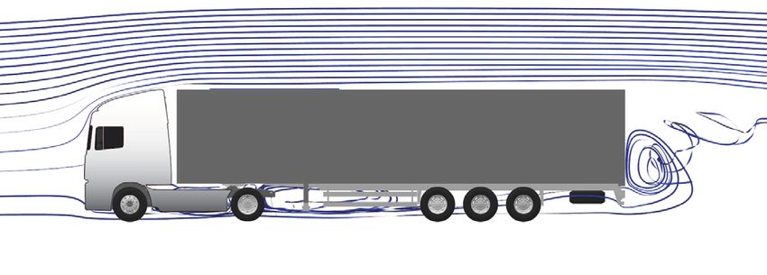
In a powertrain test, the vehicle components downstream of the powertrain such as axle,
tires, and air drag; the driver; and the duty cycle are simulated by a virtual, real-time
vehicle model. The powertrain dynamometer uses the road inclination of the drive cycle
and the vehicle characteristics to inform the controller what resistive torque must be
applied to the powertrain. The driver model takes into consideration the current vehicle
speed and the targeted speed profile and commands an accelerator pedal position in the
powertrain controller.
The advantage of powertrain testing is that it can be used on any type of hybrid system
as well as other advanced powertrain technologies such as the deep integration3 of
engine and transmission, and waste heat recovery systems. Therefore, powertrain testing
is a certification approach that can be applied in those circumstances when the fuel
saving technologies cannot be simulated, or when the simulation method has not yet
been developed.
TU Graz identified several disadvantages for the powertrain testing approach (Silberholz
& Hausberger, 2017) and acknowledged advantages in the flexibility of the method and
in its accuracy. Most of the disadvantages identified by the TU Graz team concern higher
capital investments for the development of the test-cells, and the effort involved in the
actual testing of the powertrains.
In the U.S. Phase 2 standards (U.S. EPA & U.S. DOT, 2016), the EPA assessed the capital
investment of upgrading engine testing facilities to powertrain test-cells and found the
impact on manufacturers to be reasonable. They estimated the capital investment at $1.2
million (in 2016 dollars for all cost estimates) for manufacturers that upgrade their own
engine testing facilities and at $70,000 a year per powertrain family for manufacturers
that outsource the powertrain testing and data analysis.
Powertrain testing should receive additional attention as a potential hybrid certification
pathway. The cost and availability of powertrain test-cells and the required lead time for
converting existing engine test beds into powertrain testing facilities should be analyzed
in more detail.
3 Co-optimization in which the engine and transmission controls communicate closely to adjust shift logic and
engine operational points based on driving conditions to reduce fuel use.
8THE FUTURE OF VECTO
CERTIFICATION OF FULLY ELECTRIC POWERTRAINS
OVERVIEW OF THE TECHNOLOGY
Powertrain electrification is an important lever for the reduction of CO2 emissions from on-
road freight and passenger transportation. By 2030, fully electric powertrains can reduce
the well-to-wheel emissions of long-haul trucks in Europe by more than 80% while at the
same time reducing the total cost of ownership (Moultak, Lutsey, & Hall, 2017).
Battery electric powertrains have been present in the European HDV market in small
numbers for more than a decade, as shown in Figure 4. In 2007, the heavy-duty battery
electric market was composed of mostly 5.5-tonne delivery vans produced by the
short-lived British company Modec. In 2009, the first electric buses came into the market
in small numbers. However, since 2015 the electric truck and bus markets have been
growing at considerably faster rates. The latest data4 available show that electric truck
registrations reached 434 units and bus registrations 672. This represents six times the
2015 figures for buses and 10 times for trucks. Cumulatively from 2005 to 2018, close to
2,900 electric trucks and buses were put in the market, with 2018 alone accounting for
1,100 units. In 2018 electric vehicles represented 2.4% of the bus market and 0.12% of the
truck market.
1,200
Electric vans and trucks Electric buses
1,000
Vehicle registrations per year
800
600
400
200
0
2005 2006 2007 2008 2009 2010 2011 2012 2013 2014 2015 2016 2017 2018
Figure 4. Electric trucks and buses registered in the EU from 2005 to 2018.
The largest electric bus market is the Netherlands with 22% of cumulative EU sales from
2005 to 2018, followed by the United Kingdom with 14%, and Germany with 11%. BYD
and Solaris were the leading electric bus producers in 2018, each accounting for around
20% of the market. VDL, which in 2017 placed the most electric buses in the European
market, attained a 13% market share in 2018. The European market is quickly ramping up,
and most of the incumbent bus manufacturers—Daimler, Scania, MAN, Volvo, and Iveco—
are expanding their electric bus portfolios and scaling up production (Mathieu, 2018).
The biggest electric truck market is Germany. It accounted for 54% of cumulative electric
truck registrations from 2005 to 2018. In 2018 the leading electric truck maker was
StreetScooter, totaling 214 units of its 4-tonne model Work XL. While incumbent vehicle
manufacturers have not placed many electric trucks in the market, they are ramping
up development efforts, particularly in the weight segment over 7.5 tonnes. Nearly all
major European truck manufacturers have announced production of electric trucks in
4 Content supplied by IHS Global SA; Copyright © IHS Global SA, 2018.
9ICCT WHITE PAPER
coming years. Table 3 shows a summary of the current and planned zero-emission truck
offerings in Europe of more than 7.5 tonnes. While there are few zero-emission trucks in
production, zero-emission tractor-trailers are still in the prototype stage.
Table 3. Planned electric truck portfolio in the EU with gross vehicle weights above 7.5 tonnes.
Model Stage Production GVW Battery Range Source
(Mitsubishi Fuso,
eCanter In production 7.5 tonne 83 kWh 120 km
Daimler 2017)
Trucks Customer
eActros 2021 26 tonne 240 kWh 200 km (Daimler AG, 2018)
tests
Customer (electrive.net,
eTGM, 6x2 2021 26 tonne 225 kWh 200 km
tests 2018)
MAN Customer (eurotransport.de,
eTGM, 4x2 2021 32 tonne 149 kWh 130 km
tests 2018)
CitE Prototype 2021 15 tonne 110 kWh 100 km (MAN AG, 2019)
Customer
FL Electric 2019 16 tonne 300 kWh 300 km (AB Volvo, 2018a)
Volvo tests
Trucks Customer
FE Electric 2019 27 tonne 300 kWh 200 km (AB Volvo, 2018b)
tests
Customer (Renault Trucks,
D Z.E. 2019 16 tonne 300 kWh 300 km
Renault tests 2018)
Trucks Customer (Renault Trucks,
D Wide Z.E. 2019 26 tonne 200 kWh 200 km
tests 2018)
Customer Not
LF Electric 19 tonne 222 kWh 220 km (DAF, 2018a)
tests announced
DAF
Customer Not
CF Electric 37 tonne 170 kWh 100 km (DAF, 2018b)
tests announced
R 450 Hybrid Customer Not Not apply
Scania 40 tonne 10 km (battery) (Scania AB, 2018)
(pantograph) tests announced (overhead)
Customer Not 18/26/40
E-Force EF18/26 105 – 630 kWh Up to 500 km (E-Force AG, 2019)
tests announced tonne
T5 Production (US, China) 7.5 tonne 155 kWh 250 km (BYD, 2018)
BYD* T7 Production (US, China) 11 tonne 221 kWh 200 km (BYD, 2018)
T9 Production (US, China) 36 tonne 435 kWh 270 km (BYD, 2018)
Customer
Tesla Semi 2019 (US) 36 tonne Not announced 800 km (Tesla, 2019)
tests (US)
Nikola Tre (battery) Prototype 2023 40 tonne 500 – 1,000 kWh Up to 650 km (Nikola, 2019)
Nikola Tre (fuel cell) Prototype 2023 40 tonne 320 kWh 1200 km (H2) (Nikola, 2019)
*BYD electric trucks are not yet available in Europe; a roll-out in the EU was announced (electrive.com, 2019).
CERTIFICATION OPTIONS
Fully electric powertrains do not produce CO2 emissions directly and thus are certified
under the CO2 emissions regulation as zero-emission vehicles. Still, electric vehicles have
other metrics of interest, such as electric drive range and energy consumption. These
metrics are of relevance to early adopters for making investment decisions and can be
used by regulatory agencies to tailor the regulatory incentives for zero-emission HDVs.
Currently, there is no certification approach for the driving range of HDVs. Truck and bus
manufacturers employ their own methodologies and boundary conditions to estimate
the driving range of their products, as used to be the case for the fuel consumption of
combustion engine powertrains before the VECTO-based certification was introduced.
The rapid uptake of electric buses and the expected increase in zero-emission truck
offerings (see Table 3) warrant the development of an energy consumption and
10THE FUTURE OF VECTO
driving range certification methodology that is compatible with the current regulatory
framework for the certification of CO2 emissions and fuel consumption.
VECTO’s model architecture can be easily adapted to estimate the electric driving
range of HDVs. Still, development efforts are focusing first on the more complex hybrid
certification approach. In any case, estimating electric driving range is a necessary element
for the certification of plug-in hybrid trucks, and a methodology to estimate range will
have to be integrated within the structure of the VECTO hybrid model. It is not clear
whether VECTO will include electric driving range as a certification metric or whether it
will continue to be used exclusively for CO2 and fuel consumption certification.
The simulation of electric powertrains in VECTO is more straightforward than the
simulation of hybrid powertrains, since the energy management strategy does not need
to account for the interaction between conventional and electric powertrain components.
The extension of VECTO to simulate electric-only powertrains can be accomplished by
extending VECTO’s model architecture with additional electric modules.
In VECTO’s backward-looking5 calculation, a Driver module converts the drive cycle
into an acceleration request. The information is passed to the Vehicle module, which,
on the basis of total vehicle mass, drag coefficient, and rolling resistance, converts the
acceleration request into a force request. The Wheel module then converts the force
request into a torque request at the wheel hub and passes the information to the other
powertrain components. In a final step, the Engine module receives the torque request
from the powertrain and locates the operating point on the engine map, translating
the torque and energy flows into fuel consumption values. Using this existing VECTO
architecture, electric energy consumption and driving range can be simulated with
the aid of additional modules that represent the key components of the electric
powertrain, such as battery, inverter, and motor. An example of a modified VECTO
architecture for the simulation of an electric HDV with a central electric motor is shown
in Figure 5. Until the component certification procedures for the electric componentry
are developed, the simulation tool can make use of generic data as intended for the
first iteration of VECTO hybrid.
5 In real operation, the driver commands the engine to provide torque at the wheels. In backward models, the
simulation occurs in the opposite direction than in the actual vehicle; the calculation goes from wheel to engine.
11ICCT WHITE PAPER
90 10
Reduce acceleration request
80 8
70 6
Driving
cycle or operate the brakes
Driver
60 4
Speed (km/h)
Grade (%)
50 2
40 0
30 -2
20 -4
10 -6
Acceleration
0 -8 request
0 2 4 6 8 10 12 14 16 18 20 22 24 26
Distance (km) Rolling
resistance Vehicle weight
coefficients Air drag area
FRR Vehicle
Force
request
Wheels
inertia
Wheels
Torque
request 5x10⁴ 1300
1500 1100 Torque loss / Nm
1400 1200
4x10⁴
Torque 900
Input Torque (Nm)
1000
loss 3x10⁴
Axle
700 600
800
500
2x10⁴ 400
300
1x10 4
200
100 Torque 100
90 request 0
0 500 1000 1500 2000
Motor/generator efficiency (%)
Input speed (1/min)
Efficiency
80
70
60
Normalized load: and torque
1%
limits
Electric machine
50 5%
%
10%
40 15%
%
20%
30 %
40%
%
60%
20 %
80%
10
%
0
100%
Power/energy
0
0 20 40 60 80 100
request
Normalized speed (%)
Energy No
request
Auxiliaries Battery/Inverter Success?
Charge/discharge efficiency Yes
Energy and power limits
100
efficiency (%)
95
Write simulation
Battery
90
Modules already in VECTO
85
80
0 5 10 15 20 25 30 35 40 results and advance
New modules required
Charge/discharge rate (C)
100
to next point
power limit (%)
Normalized
80
60
40
20
0 20 40 60 80 100
State of charge (%)
Figure 5. Example of a modified VECTO architecture for the simulation of an electric powertrain
with a single central electric motor.
RECOMMENDATIONS FOR THE CERTIFICATION OF FULLY
ELECTRIC HDVS
The simulation of electric-only powertrains can be accomplished by slight modifications
of VECTO’s architecture to accommodate new modules for the electric powertrain
components. These new modules are being developed in the context of the extension of
VECTO to simulate hybrid powertrains.
Prioritizing the development of a certification methodology for electric range will
enable the differentiation of zero-emission HDVs based on their zero-emission driving
range and payload. This differentiation is crucial for establishing incentives targeted at
the development of zero-emission vehicles in the harder-to-electrify HDV segments,
which are in turn also the ones with the highest contribution to CO2 emissions from
on-road freight.
12THE FUTURE OF VECTO
WASTE HEAT RECOVERY
OVERVIEW OF THE TECHNOLOGY
Combustion engines convert less than half of the fuel’s chemical energy into usable work
at the crankshaft. The rest of the energy is dissipated as heat into the environment. Hot
exhaust gases account for 35% of this wasted thermal energy and the cooling circuit
accounts for 10% (Thiruvengadam et al., 2014). Waste heat recovery (WHR) systems
attempt to recoup some of this energy and transform it into usable forms of energy
including mechanical work or electric energy. Two main types of WHR approaches have
been investigated in the past:
1. Bottoming cycles: The coolant fluid, engine oil, EGR flow, and exhaust gases
are heat sources that can be used to drive a separate heat engine. Typically, the
bottoming cycle and associated heat engines are designed on the principles of the
ideal organic Rankine cycle (ORC) (Mahmoudi, Fazli, & Morad, 2018).
2. Thermoelectric generators: The temperature differential between the exhaust
gases and the environment is exploited by semiconductors exhibiting a strong
thermoelectric effect to generate electricity. They have, however, lower thermal
efficiency than bottoming cycles (Orr, Akbarzadeh, Mochizuki, & Singh, 2016).
Due to the higher thermodynamic efficiency and, thus, the greater fuel consumption
benefits, most of the recent WHR research and development efforts have been on
ORC systems. In an ORC-WHR system the waste heat from multiple sources is used
to evaporate an organic working fluid in a heat exchanger. The evaporated fluid is
then passed through a turbine or a piston expander to create mechanical work. The
mechanical work can be provided directly to the engine’s crankshaft or converted into
electric energy and stored as such. The working fluid is condensed in another heat
exchanger and then its pressure is increased by a feed pump to restart the cycle. Figure
6 illustrates a typical ORC-WHR system.
Generator
Organic working fluid
Expander
Evaporator
Air in Exhaust
out
Feed pump
Coolant
Engine Condenser
Figure 6. Typical WHR system architecture for capturing exhaust heat and converting it to electric
energy (e-WHR).
Waste heat recovery systems have been identified by different stakeholders as a
promising technology for the reduction of fuel consumption and CO2 emissions of
13ICCT WHITE PAPER HDVs, particularly in long-haul operation. Several studies have been carried out to quantify the potential of ORC-WHR systems for European long-haul trucks. The results indicate a range of fuel consumption reduction between 1.5% and 7.2% (Bettoja et al., 2016; Glensvig et al., 2016; Grelet, Reiche, Lemort, Nadri, & Dufour, 2016; Yang, Grill, & Bargende, 2019). Although ORC-WHR systems are not offered on any in-production vehicle, several component suppliers, such as MAHLE (Scharrer, 2018), BorgWarner (Liu et al., 2017), and Eaton (Subramanian, 2017), have production-ready components that can be readily integrated by truck manufacturers. CERTIFICATION OPTIONS The design of the certification methodologies in the United States and China enables the measurement of powertrains equipped with WHR systems. In the United States, the fuel consumption benefits of WHR systems that are mechanically coupled to the engine are fully captured by the U.S. engine mapping approach, called cycle-average mapping. For e-WHR systems, U.S. powertrain testing provides an alternative certification pathway. In China, the fuel consumption certification for base vehicles is done on the chassis dynamometer. Thus, the methodology captures all powertrain technologies, including WHR systems. Given the unbreakable relationship between engine and WHR system, the latter can be considered an engine component. An engine test protocol for generating the input data required by VECTO already exists. Thus, in principle, WHR systems are already covered by the current methodology. However, the accuracy and technology limitations imposed by the current method, presented in detail below, warrant the examination of additional certification pathways. As was the case for hybrid powertrains, several certification options exist for including WHR systems in the European CO2 certification framework. The following paragraphs describe the key elements, advantages, and disadvantages of possible certification approaches for WHR systems. The following methodologies are considered: 1. Current engine mapping method. 2. WHR correction factors for current engine mapping method. 3. Cycle-average mapping. 4. VECTO simulation with WHR component test. 5. Full simulation in VECTO. Current engine mapping method Currently, two types of tests are necessary for generating the engine data used as input by the simulation-based CO2 certification procedure. First is the fuel consumption mapping cycle. In this test, the steady-state fuel consumption over about 100 operating conditions is measured on the engine dynamometer. To achieve steady-state conditions, each operating point is allowed to stabilize for about one minute. The results of this test directly provide the lookup table used in VECTO simulations for the interpolation of fuel consumption. The second test is the Worldwide Harmonized Transient Cycle (WHTC), which is used to perform a transient correction to the steady-state measurements. In its current form, the engine certification approach established in the EU does not accurately capture the effect of WHR systems. The following limitations are identified: 14
THE FUTURE OF VECTO

»» In the fuel consumption mapping test, the one-minute stabilization time is
   insufficient because of the large thermal inertia of WHR systems. As a result, the
   current steady-state test overestimates the fuel benefits of WHR systems at low
   loads and underestimates them at high loads.
»» The current methodology to account for transient operation and cold-start uses
   the WHTC test to determine a set of correction factors. WHR systems are highly
   sensitive to exhaust temperature fluctuations. It has not yet been determined
   whether the correction factor based on the urban, rural, and motorway sections
   of the WHTC are representative of the Urban Delivery, Regional Delivery and Long
   Haul VECTO cycles for WHR systems. Furthermore, the WHTC correction does not
   consider the change in engine load and thus in exhaust temperature stemming from
   different payloads.
»» In the case of electric WHR systems mechanically decoupled from the engine, such
   as the e-WHR from Figure 6, the fuel consumption reduction cannot be directly
   quantified in the current engine mapping procedure.
»» WHR system effectiveness is dependent on condenser effectiveness, or how
   efficiently heat can be removed from the WHR system. This cooling performance
   is influenced by the integration of the WHR system with the vehicle, ambient
   conditions, vehicle speed, and other factors. Engine dynamometers have cooling
   capacities that go significantly beyond those found in vehicles. Consequently, the
   engine test protocol, which is based on UNECE Regulation 49, is not able to capture
   these cooling interactions between vehicle and the WHR system.

WHR temperature correction factors for current engine mapping method
The current certification pathway being considered by the European Commission
contractor, TU Graz, involves the use of correction factors to account for the limitations
of the current engine mapping procedure without needing to modify the procedure.

As mentioned, the stabilization time of the current engine test is too short to reach
the steady-state temperature at the WHR inlet, potentially overestimating the WHR
work at low load and underestimating it at high load. To circumvent this limitation, a
methodology based on temperature correction factors is being examined. The proposed
temperature correction factors would mimic the WHTC current transient correction
approach in place for fuel consumption.

Using exhaust temperature measurements from the steady-state engine test, the average
temperature over the different portions of the WHTC can be estimated by interpolating
the steady-state map. This temperature estimate is then compared with the actual
average temperature measured over the WHTC sections. The ratios of the temperature
estimates from the steady-state map interpolation to the WHTC measurements are the
proposed temperature correction factors. A temperature correction factor can then be
used to address the issues with the stabilization time of the steady-state map, or the
overestimation of WHR work at low load and underestimation at high loads.

In a preliminary validation by TU Graz, the temperature correction factors reduced
the difference between modeled temperature from the steady-state interpolation and
the measured values. However, payload-dependent deviations were still observed. An
approach to reduce these deviations is being explored. The proposed methodology
would involve the development of a WHR function, a linear regression model to
characterize the WHR power output as a function of average WHR temperature
(Hausberger, 2019).

The methodology outlined above has the advantage that it builds upon the current engine
certification approach, ensuring the coherence between non-WHR engines being certified

                                                                                        15
ICCT WHITE PAPER
since the start of 2019, and future WHR-engine combinations. The proposed approach,
however, raises a number of additional challenges that need to be analyzed carefully:
»» The temperature correction factors can reduce deviations observed between
interpolated and measured exhaust temperatures. Still, they cannot be used directly
to estimate the differences between the interpolated WHR work and the actual
work. A characteristic function relating WHR work and temperature is required.
»» A characteristic WHR function must be defined based on experimental data. This
would imply additional tests on the engine dynamometer or an additional WHR-only
component test.
»» The correction factors are likely to be specific to the vehicle types, driving
cycles, and simulated payloads currently defined in the EU regulatory framework.
Consequently, the approach is sensitive to changes in these parameters and would
need to be updated if the mission profiles or regulatory payloads change.
While WHR temperature correction factors have the potential to address many
of the shortcomings of the current test protocol, their effectiveness and ease of
implementation require further analysis.
The applicability to e-WHR systems and the interaction between test-cell cooling and
WHR condenser performance are not addressed by this certification approach and
would need to be considered separately.
Cycle-average mapping
The high sensitivity of WHR systems to exhaust temperature variations, and thus to
transient operation, demands a robust transient correction methodology. For the U.S.
Phase 2 GHG standards, the EPA in close cooperation with engine, transmission, and
vehicle manufacturers developed a new fuel consumption mapping methodology called
cycle-average mapping (U.S. EPA & U.S. DOT, 2016, §1036.540; Zhang et al., 2016). The
cycle-average mapping process in the context of WHR certification can be summarized
in the following steps (see Figure 7).
Engine cycle generator
Standard vehicle
configurations
Engine cycles
full load and
Engine mapping motoring curves
Engine
dyno testing
Fuel consumption Cycle average Fuel consumption
and CO2 emissions map vs. N/V, and W
System and
component data of
vehicle to be certified
Figure 7. WHR system certification using the cycle-average map approach.
»» Generate the full load and motoring curves of the engine-WHR combination.
»» Define several standard configurations that span the range of trucks to be certified.
16THE FUTURE OF VECTO
»» Using the measured full load and motoring curves, simulate standard vehicle
configurations in VECTO over different drive cycles—distance versus target speed
and grade—and from the simulation results create respective engine cycles—engine
speed versus engine torque.
»» Test the engine-WRH combination on a dynamometer over the engine cycles
defined in the previous step. For each test, report the cumulative fuel consumption.
In the case of mechanically decoupled WHR systems, report the positive WHR work.
»» Based on the test results, create a regression model for fuel consumption over the
certification tests using independent variables that can characterize the whole
vehicle operation. Researchers at the EPA assessed several regression possibilities
and determined that a linear regression model using the ratio of average engine
speed to average vehicle speed (N/V) and positive engine work (W) as the two
independent variables resulted in the best accuracy (Zhang et al., 2016). Since
the variable N/V is dependent on the drive-tire size, axle ratio, and transmission
gear ratios, it can capture different powertrain configurations. The engine work,
W, is useful for capturing average engine efficiency across different cycles (Zhang,
Sanchez, & Spears, 2015). Figure 8 shows the visual representation of an example
regression surface.
»» By using the regression model, VECTO could estimate the fuel consumption and
CO2 emissions benefits of WHR systems in different vehicles by performing an
interpolation over the resulting regression surface.
14
13
Fuel mass over cycle (kg)
12
11
10
9
8
7
30
En 28 65
gin
et 26 60
ov 55
eh
icle 24 50
spe Wh)
ed
,N 22 45
rk, W (k
/V 40 ine wo
(rp
m/ 20 35 Eng
kp
h)
Figure 8. Example of regression surface for cycle-average mapping
The main advantage of the cycle-average engine test procedure is that it produces
accurate results in both steady-state and transient conditions. Since the transient
correction is done over the same drive cycles used by VECTO, it is more accurate than
a transient correction based exclusively on the WHTC cycle. This is crucial for systems
exhibiting high sensitivity to transient operation, such as WHR systems. Furthermore, the
17ICCT WHITE PAPER cycle-average methodology has already been extensively validated by the EPA with the support of truck manufacturers in the EU. Therefore, its performance is well documented and should be familiar territory for HDV manufacturers. As in the previous case, the applicability to e-WHR systems and the interaction between the test-cell cooling and WHR condenser performance are not addressed by this certification approach and would need to be considered separately. VECTO simulation with WHR component test This approach involves the development of a WHR component test as a stand-alone unit, eliminating the need for detailed simulation of the processes taking place inside the WHR. The data from the component test are then used to generate a mathematical model of the WHR system, in much the same way as is currently done for engines and other complex components. In other words, the model would consist of a two- dimensional look-up table that would output the work generated by the WHR system based on the input exhaust temperature and mass flow. Given that those two quantities are not currently being measured as part of the fuel consumption mapping procedures of the engine, the test must be modified to capture these data and to allow the steady- state measurement of exhaust temperatures, such as the longer thermal stabilization periods in the fuel mapping. Furthermore, the component test must capture the effects of the thermal inertia of the various WHR components to avoid over- or underestimating the work output of the system in transient operation. VECTO’s architecture would also need to be adapted to accommodate such a model. The operation and effectiveness of a WHR system depends heavily on its interaction with other vehicle systems, most notably with the cooling system. In the absence of sufficient cooling power to deal with heat rejection from the condensation process, the WHR has to limit the exhaust mass flow it accepts to accommodate to the cooling conditions, thus reducing the WHR power output. Since VECTO does not include any simulation of the cooling system, the development of a cooling model would be a prerequisite to capturing these interactions. In real vehicles, interactions between components and systems would be dictated by manufacturer-specific control algorithms. Thus, a generic control strategy would need to be developed to capture the model interactions within VECTO in a way that is representative of the actual control strategies. Accurately modeling these interactions among the vehicle, engine, electric storage system, and WHR systems poses several challenges that would require significant resources and time to overcome. Full simulation in VECTO The complete simulation of WHR systems and their interaction with the rest of the vehicle model require the development of a significant number of additional mathematical models in VECTO and additional component tests. The main components are the heat exchangers—evaporator, condenser, and recuperator—the feed pump, expander, and working fluid. In addition, the connection of the WHR to the rest of the powertrain must be modeled, either by a mechanical connection with associated power loss, or by an electrical system with its associated electrical efficiency. To add further complexity, different options are available for some of the WHR components with different thermodynamic properties. Lastly, the thermal, mechanical, and electric coupling of WHR systems with the rest of the vehicle must be accurately modeled. As a result of the large number and variety of subcomponents, the full simulation of WHR systems and their interaction with the rest of the vehicle presents significant challenges for using this approach as a certification methodology. 18
You can also read