De Concorde aux nouveaux projets d'avions supersoniques - From Concorde to new supersonic aircraft projects - AAE
←
→
Page content transcription
If your browser does not render page correctly, please read the page content below
Summary

De Concorde
aux nouveaux projets
d’avions supersoniques
From Concorde
to new supersonic
aircraft projects

  AAE Dossier # 46       2019
Summary

DE CONCORDE AUX
NOUVEAUX PROJETS
D’AVIONS SUPERSONIQUES

FROM CONCORDE
TO NEW SUPERSONIC
AIRCRAFT PROJECTS

AAE Dossier #46     2019
Summary
© AAE – 2019
Tous droits réservés / All rights reserved
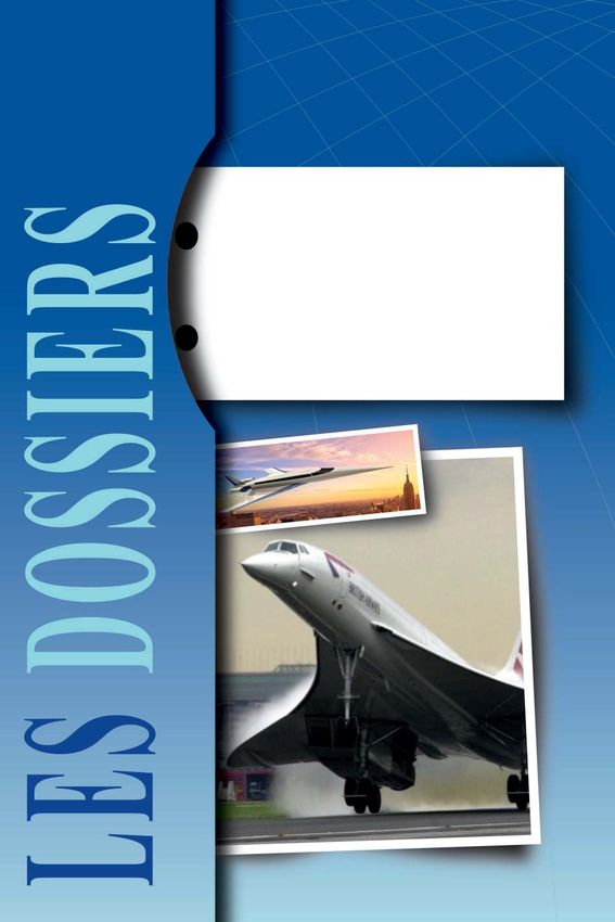
Crédits photo couverture / Cover credits:
Spike S-512 © Spike / Concorde © British Airways
Boom Overture © Boom / Aerion AS2 © Aerion
AAE
Ancien Observatoire de Jolimont
1 avenue Camille Flammarion
31500 Toulouse - France
Tel : +33 (0)5 34 25 03 80
contact@academie-air-espace.com
www.academieairespace.com
ISBN 978-2-913331-80-8
ISSN 1147-3657
Dépôt légal : juillet 2019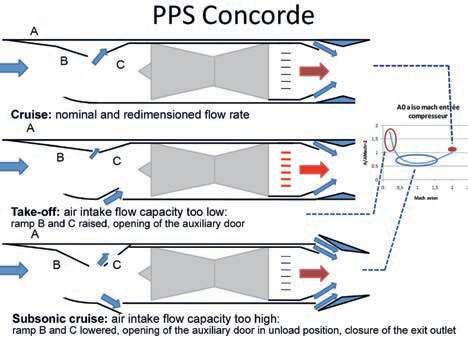
Summary

                Dossiers récents / Recent Dossiers

n°45 Cybermenaces visant le transport aérien, 2019
     Cyberthreats targeting air transport, 2019
n°44 Le transport de passagers par appareils à voilure tournante à l’horizon 2050, 2018
     Rotary wing aircraft for passenger transport by 2050, 2018
n°43 L’Espace au service de la sécurité et de la défense ;
     pour une nouvelle approche européenne, 2018
     Space systems supporting security and defence; a new European approach, 2018
n°42 Aviation plus automatique, interconnectée, à l’horizon 2050, 2018
     More automated, connected aviation by 2050, 2018
n°41 Les disparitions d’avions : une question pour les transports aériens, 2017
     Missing aircraft: an issue facing air transport, 2017
n°40 Présent et futur des drones civils, 2015
     Present and future of civilian drones, 2015
n°39 Matériaux aéronautiques d’aujourd’hui et de demain, 2014
     Aeronautical materials for today and tomorrow, 2014
n°38 Comment volerons-nous en 2050 ?, 2013
     Flying in 2050, 2013
n°37 Le Traitement des situations imprévues en vol, 2013
     Dealing with unforeseen situations in flight, 2013
n°36 Quel avenir pour l’industrie aéronautique et spatiale européenne ?, 2013
     What future for European aeronautics and space industries?, 2013
n°35 Trafic aérien et météorologie, 2011
     Air traffic and meteorology, 2011
n°34 Une stratégie à long terme pour les lanceurs spatiaux européens, 2010
     Long-term strategy for European launchers, 2010
n°33 Les Aéroports face à leurs défis, 2010
     Airports and their challenges, 2010
n°32 Prise de risque : conclusions et recommandations, 2009
     Risktaking: conclusions and recommendations, 2009
n°31 Pour une approche européenne à la sécurité dans l’espace, 2008
     For a European approach to security in space, 2008
n°30 Le Rôle de l’Europe dans l’exploration spatiale, 2008
     The role of Europe in space exploration, 2008
n°29 Le Transport aérien face au défi énergétique, 2007
     Air transport and the energy challenge, 2007

                                                                                          5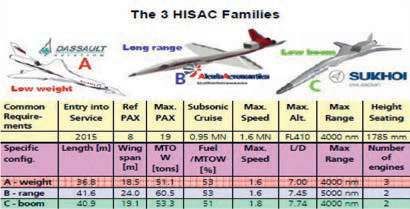
TABLE OF CONTENTS

1- Foreword ...........................................................................................10

2- Introduction ......................................................................................14

3- Concorde ..........................................................................................18
    Operational performance ..................................................................................... 20
         Lift-to-Drag ratio (L/D) ............................................................................. 22
         Thrust levels, specific fuel consumption and weight of the propulsion system ........24
         Definition of operational weights ................................................................ 26
         Fuel consumption with relation to the new CO2 standard ................................. 28
    Airport noise ...................................................................................................... 30

4- Concorde B .......................................................................................34
    Aerodynamics .................................................................................................... 34
    Propulsion.......................................................................................................... 36
    Other modifications ........................................................................................... 36

5- Future supersonic transport aircraft (ATSF) .......................38
    Improving aerodynamic L/D ratio ......................................................................... 38
    Improved specific fuel consumption and engine noise .......................................... 42
    Development costs and cost price ....................................................................... 44

6- Noise during cruise, sonic boom .............................................46

7- Supersonic business aircraft ....................................................50
    Use of business jets ........................................................................................... 50
    European project: HISAC .................................................................................... 52
    New aircraft proposed ......................................................................................... 56
        Aerion: cruise at Mach 1.4 ........................................................................ 56
        Spike S-512: cruise at Mach 1.6 ...............................................................62
        Boom: cruise at Mach 2.2 .......................................................................64
        Summary of the proposals ........................................................................ 68
    Considerations regarding development programmes ............................................ 76

8- Conclusion ........................................................................................82
    Appendix 1: Requirements for the development of a new aircraft ....................90
    Appendix 2: Concorde propulsion ..............................................................................94

   6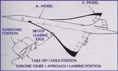
Summary
Table of figures
Figure 1: A production Concorde, with extended rear......................................18
Figure 2: Concorde, the prototype and production aircraft ..............................20
Figure 3: Reminder of certain physical laws
(simplified equilibrium of an aircraft in level flight) ............................20
Figure 4: Internal temperatures of Olympus and subsonic engines ................24
Figure 5: Weights of the propulsion system of Concorde as compared
with subsonic aircraft .......................................................................26
Figure 6: Concorde: weight distribution at take-off...........................................28
Figure 7: Comparison between Concorde and current aircraft
with regard to the new CO2 standard for subsonic aircraft ...............28
Figure 8: Comparison of airport noise levels of Concorde
and current aircraft ............................................................................30
Figure 9: Noise evolution as a function of jet speed (same thrust)..................32
Figure 10: Aerodynamics envisaged for Concorde B ........................................34
Figure 11: Engine envisaged for Concorde B ....................................................36
Figure 12: Evolution of supersonic designs 1980-2000 .....................................40
Figure 13: Commercial layout and cabin width ..................................................40
Figure 14: Example of a variable cycle engine ..................................................44
Figure 15: QueSST demonstrator configuration C606 .......................................46
Figure 16: Use of business jets as function of their resale prices .....................50
Figure 17: European HISAC project...................................................................52
Figure 18: The three HISAC families .................................................................54
Figure 19: Aerion SBJ project ............................................................................56
Figure 20: Aerion AS2 project ............................................................................56
Figure 21: Aerion AS2 project ............................................................................58
Figure 22: Time savings promised by Aerion .....................................................60
Figures 23 and 24: GE Affinity Engine .............................................................................60
Figure 25: Spike S-512 (2014) ...........................................................................62
Figure 26: Spike S-512 (2015-2017) ..................................................................62
Figure 27: Boom: the model, and the “Dream team” .........................................64
Figure 28: First Baby Boom XB1 .......................................................................66
Figure 28 b-c: Baby Boom XB1................................................................................66
Figure 29: Concorde and summary of proposed projects ..................................70
Figure 30: Concorde and aerodynamic characteristics
of proposed projects .........................................................................70
Figure 31: Comparison of the characteristic weights of Concorde
with the proposed projects ................................................................72
Figure 32: Comparison of ranges as proposed by
manufacturers and estimated ..........................................................76
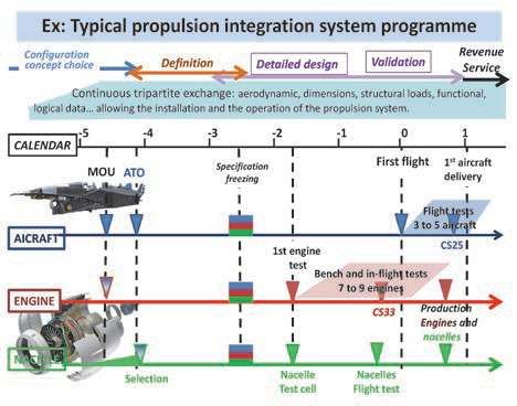
Figure 33: Lifespan of a conventional subsonic aircraft programme .................78
Figure 34: Integration plan for a subsonic aircraft propulsion unit .....................80
8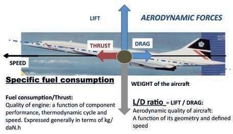
Summary

1       FOREWORD

Several supersonic business jet projects have been announced in recent years,
mainly from the United States. Europe is remaining very cautious on the subject,
despite a certain experience in the field, which combines the knowledge of
researchers and industrialists. The Air and Space Academy therefore decided to
make an initial assessment as to the (mainly technical) feasibility of the various
proposals. To do so, AAE based its study on lessons learned from the Concorde
supersonic transport aircraft, the only aircraft in this segment to have entered
commercial service.
This analysis reveals a great spread in the maturity level of the different projects.
Some embryonic ventures have given no sign of life for months, while the slow
progress of others demonstrates that continuous evolutions can lead to difficult
decisions in defining the pre-production model. Entry into service dates are
regularly put back accordingly since, with the specifications indicated, and despite
significantly lower ambitions for cruising speed, these missions are unachievable
due to the same physical laws confronting European studies in the late 1990s.
AAE has no intention, at this stage, of setting out any position as to the
acceptability of ecological aspects (linked to emissions and noise pollution).
These will need to be dealt with at the international level by negotiating new rules,
probably in the form of derogations from the increasingly stringent requirements
for subsonic transport aircraft. It is strongly recommended that Europe participates
actively in these negotiations.
Likewise any in-depth economic study is considered premature because of doubts
as to the feasibility of these missions (with the announced characteristics), and
due to the nature of the market (for which profitability is not the main criterion).

 10
Summary

AAE DOSSIER No.46                  NEW SUPERSONIC AIRCRAFT PROJECTS

This Dossier 46, resulting from a robust technical study, aims to provide clear,
useful information to political, technical and financial decision-makers as to the
scale of the challenges to be met by research organisations and industry in order
to develop supersonic civil air transport.

                                                           Anne-Marie Mainguy
                                  President of the Air and Space Academy (AAE)

 12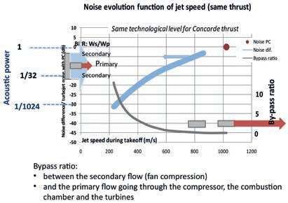
Summary

2       INTRODUCTION

At a time when supersonic aircraft projects, mainly business jets, are resurfacing,
this document begins by analysing the characteristics of Concorde, the only
long-range commercial supersonic to enter commercial operation. It goes on to
examine projects developed in the 1980s and 90s by Aerospatiale, BAe and
Boeing before assessing those proposed today by various start-up design offices.
The present study first highlights the main hurdles to commercial success of
Concorde, i.e. very high operational costs (50 % maintenance and 10% fuel
consumption with 800 kg of fuel being consumed between Paris and New York per
passenger compared to less than 140 kg today), too short range, a rapidly
prohibitive take-off noise at commercial airports and a sonic boom during cruise
that resulted in a ban on supersonic flight over land, severely limiting its
operational advantage. In addition, time differences meant that while the
East-West routes were attractive to target customers (arrival in local time before
take-off time), West-East routes were much less so.
This section relies on information from freely available literature, in particular from
the website Concordesst.com, as well as the memories of both the author and
experts who worked on this programme.
Then an overview is provided of the results of the different studies conducted in
Europe up to 2009 concluding, for transport missions with average carrying
capacity, with their infeasibility.
The ensuing analysis, completed in December 2018, is limited to an assessment
of the technical feasibility (possible achievement of announced missions) of
recent supersonic aircraft pre-projects, mainly business jets, in the light of data
available so far on their characteristics together with lessons learned from the
Concorde programme.

 14
Summary

AAE DOSSIER No.46                   NEW SUPERSONIC AIRCRAFT PROJECTS

Important note: the Concorde programme, launched in 1962, was developed in
the absence of environmental requirements, on the back of numerous pre-studies
carried out by experienced Franco-British teams. The French teams had already
developed and flown supersonic fighter prototypes such as the Trident (SNCASO)
and built transport aircraft like the SE 210 Caravelle (SNCASE) before merging
into Sud-Aviation to produce the Concorde. British teams had likewise had
experience on their own projects. In spite of this experience and the combined
national support, the first Concorde test flight was only carried out in 1969, seven
years after its launch, and the first commercial flight seven years later, in 1976,
i.e. after 14 years of development. This demonstrates the extreme difficulty of
developing a supersonic transport aircraft due to the many requirements that must
be met, especially if these evolve in the course of development! Appendix 1
describes in slightly more detail the development constraints for new aircraft.

 16
Summary

3         CONCORDE

The performance goal (of linking the West Coast of Europe to the East Coast of
the United States) and the technical difficulties encountered during development,
inherent to any new, ambitious project, led to a modification in the definition of this
aircraft and an increase in its take-off weight for the same cabin:
               “Width / height / cabin length: 2.63 m / 1.96 m / 39.32 m.”
The target range could not be under 3,500 NM (6,500 km) in order to reach New
York (3,150 NM) or Washington (3,346 NM), whatever the windspeed.
Manufacturers’ mission pledge to the DGAC was to carry a payload of 10 t
(22,000 lbs) at standard temperature 5°C on the Paris-New-York route.

       Figure 1: A production Concorde, with extended rear.
The characteristics of the three prototypes highlight the evolving design
(Figure 2):
                            Prototype 001      Preproduction 01       Production 1
                            2 March 1969                            6 December 1973
 Length (m)                     51.8                60.10                61.66
 Wingspan (m)                   23.8                 25.6                 25.6
 Take-off weight (t)          135-155                                    185.07

 18
Summary
AAE DOSSIER No.46 NEW SUPERSONIC AIRCRAFT PROJECTS
Prototype 001.
Production.
Figure 2: Concorde, the prototype (above) and production aircraft (below).
The specifications of the powerplant (Appendix 2) evolved to factor in the greater
weights; in particular the share of thrust provided by the afterburners was
increased from 9% to 17%, then to 18.5% of the total take-off thrust.
Thrust levels of production aircraft were:
• thrust without afterburner for Mach 0: 4 X 139.4 kN = 557.6 kN (125,000 lbs);
• thrust with afterburner for Mach 0: 4 x 171.3 kN= 685.2 kN (154,000 lbs).
Operational performance
Figure 3: Reminder of certain physical laws (simplified equilibrium of an aircraft
in level flight).
20Summary
AAE DOSSIER No.46 NEW SUPERSONIC AIRCRAFT PROJECTS
One essential factor of aircraft performance is its range. A first approximation of
this is given by the Breguet range equation. This is relevant for long-range flights
for which cruise accounts for 80 to 85% of fuel consumption. Concorde cruising
flight was performed at constant L/D and specific fuel consumption thanks to the
slow climb which results from the reducing fuel load. This cruise climb allowed the
aircraft to maintain flight close to optimum performance.
Speed L/D ratio Take-off weight
Range = x x Ln
g SFC Landing weight
Open literature gives indications on speed, L/D ratio and specific consumption of
engines when in cruise, along with certified aircraft weight.
Operational Take-Off Weight (TOW) and Landing Weight (LW), which are based on
empty weight (aircraft manufacturer’s responsibility) plus the combined weights of
cabin equipment, crew, catering (airline responsibility) and regulatory reserves, are
more difficult to estimate. The MTOW and MLW (Maximum Take-Off Weight and
Maximum Landing Weight) often provided are the maximum weights used for
structural calculations and are generally greater than the operational weights.
Lift-to-Drag ratio (L/D)
Information found in the literature indicates a Mach 2 L/D ratio ranging from 7.10
to 7.30. This L/D ratio varies according to the lift coefficient, and therefore
according to altitude for a given aircraft weight. Since the altitude in cruise climb
was restricted by the propulsion ceiling, it did not allow maximum L/D ratio to be
achieved. In operation the L/D ratio level was 7.14 with an aspect ratio of 1.83
(wingspan^2/wing area). These levels are 2 to 3 times lower than those of current
subsonic aircraft which have aspect ratios greater than 9.
L/D ratios found
(Concordesst.com Concorde Technical specs)
Take-off:
Zero climb 3.94
Second segment 4.97
Anti-noise procedure 6.00
Approach: 4.35
250 knots 10,000 feet 9.27
Subsonic cruise M = 0.93 11.47
Supersonic cruise 7.14
22Summary
AAE DOSSIER No.46 NEW SUPERSONIC AIRCRAFT PROJECTS
Thrust levels, specific fuel consumption and weight of the
propulsion system (see Appendix 1)
Thrust levels used
To optimise Concorde performances, a single flow, twin spool engine was used,
enhanced for supersonic flight. An afterburner provided the additional thrust
required for take-off (9% then 17% and finally 18.5%), and for transonic climb from
Mach 0.93 to 1.7.
Engine thrust levels during climb and cruise were the highest certified with no
operational time limit (about 2 hours for Concorde). While take-off temperatures
corresponded to the state of the art at the time, internal engine temperatures
(Figure 4) were significantly higher than those of current subsonic aircraft, which
have more restrictive engine regimes in climb and cruise.
The flight times of climb and supersonic cruise were therefore paramount for the
design and life of the Olympus engines.
Figure 4: Comparison of internal temperatures of Olympus and subsonic
engines (BPR: bypass ratio).
Specific consumption
The ratio of the lift-to-drag/specific fuel consumption of the engine at the start of
climb cruise provided by analysis of the Air France Performance Manual:
24Summary
AAE DOSSIER No.46 NEW SUPERSONIC AIRCRAFT PROJECTS
• varied from 5.96 at 50,000 ft (15,240 m) to 5.89 at 60,000 ft (18,288 m) at Mach 2,
i.e. a specific consumption level very close to 1.2 kg / daN.h for a L/D ratio of 7.14;
• reached 10 at Mach 0.93 during subsonic cruise.
The use of the afterburner doubled fuel consumption for a thrust increase of under
20%.
Weights of the propulsion system
Figure 5: Weights of the propulsion system of Concorde as compared
with subsonic aircraft.
The weight of the Concorde propulsion systems was close to 22,500 kg, nearly
30% of the manufacturer’s empty weight (MEW), as against 15 to 17% for
subsonic long-range aircraft (Figure 5). Nacelles, air intakes and variable
geometry nozzles, which helped manage supersonic flows while minimising
performance losses, accounted for 46% of the weight of the propulsion unit
compared to 22% for a subsonic aircraft. The afterburner increased take-off
thrust, with only a small increase in weight.
Definition of operational weights
The weights of the aircraft delivered to Air France, as well as those used by the
airline for crew, catering and onboard technical documentation, are shown in the
following table. The Operating Empty Weight (OEW) used by Air France to define
operational performance also took into account any additional weight incurred by
modifications after delivery.
Max Min
Manufacturer’s weight on delivery (kg)1 78,000 76,700
Catering + crew + flight crew doc (kg) 2,555 2,555
OEW: Aircraft ready for operation without fuel or payload (kg) 80,555 79,255
1. The manufacturer’s weight, with seats and fixed equipment, was reduced thanks to carefully
planned manufacture.
26Summary
AAE DOSSIER No.46 NEW SUPERSONIC AIRCRAFT PROJECTS
A summary of the weight distribution for Concorde can be seen in Figure 6.
Figure 6: Concorde: weight distribution at take-off.
It can be noted in Figure 6 that reserves represented 8% of the MTOW, i.e. over
15% of onboard fuel, with the choice of a diversion airport very close to J.F.
Kennedy Airport (Newark, 40 NM). Had the traditional 200 NM diversion been
used, the number of passengers would have had to be cut by ten, bringing the
payload down to 4.8% of the take-off weight instead of 5.4%.
Fuel consumption with relation to the new CO2 standard
The new CO2 standard (Figure 7), applicable to new subsonic aircraft requesting
certification after 1 January 2020 (MTOW > 60t) or 1 January 2023 (MTOW
< 60 t), limits fuel consumption per kilometre by means of the “Metric Value”.
The Concorde would have had a “Metric Value” and a fuel consumption over four
times higher than the A320neo, for equivalent floor surfaces and range, i.e.
6 times more per passenger. It would not have met this certification requirement.
Figure 7: Comparison between Concorde and current aircraft with regard
to the new CO2 standard for subsonic aircraft.
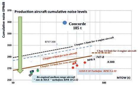
28Summary AAE DOSSIER No.46 NEW SUPERSONIC AIRCRAFT PROJECTS Airport noise Figure 8 compares the cumulative noise levels, on the three regulatory control points, of current aircraft with those of Concorde, as published on the “Salon de l’aviation.com” website. Figure 8: Comparison of airport noise levels of Concorde and current aircraft. The very high noise level (+ ~90 EPNdB compared to the latest certified twin-engine aircraft with the same range) was caused by jet noise, which is preeminent for single-flow and dual-flow engines with a low bypass ratio. The use of afterburners during the initial part of the take-off, on the runway and during climb before flyover, increased the level of sideline noise. Emitted sound power with relation to the speed of the jet is expressed in the D 2Vj8 equation (where D and Vj are respectively the diameter and speed of the jet). Deviations from current aircraft are consistent with those published in the 2012 Advisory Circular AC 36-311 for take-off and approach noise. To lose a few decibels, Aérospatiale and its partners (SNECMA and ONERA in particular) assessed the possibility of “silencers”, using theoretical studies, wind tunnel tests and the engine test bench. They used the test track of the experimental Bertin Aerotrain near Orleans and a vehicle powered by a GE J85 engine to simulate flight speed, because noise reductions demonstrated on static benches did not occur during flight tests. Pressure losses created by vortex generators installed in the nozzles, intended to reduce noise, also reduced thrust and penalised take-off and cruise efficiency. This loss of efficiency resulted in an increase in take-off weight to accomplish the target mission and, ultimately, an increase in noise. In conclusion, none of the “silencers” studied were installed. 30
Summary

AAE DOSSIER No.46                    NEW SUPERSONIC AIRCRAFT PROJECTS

To illustrate the challenge, Figure 9 gives some orders of magnitude, with
constant net thrust, of how jet noise evolves according to the jet velocities of the
engine, and the impact an increase in the associated bypass ratio would have on
the dimensions and weights of the propulsion systems. An increase of:
• 3 dB corresponds to a doubling of sound power;
• 30 dB corresponds to a sound power nearly a thousand times greater.

Figure 9: Noise evolution as a function of jet speed (same thrust).
There is a difference of almost 30 dB between the jet noise emitted by an engine
equipped with an afterburner and that emitted by the latest certified engines that
comply with regulations in force: a by-pass ratio of 12 and average ejection speed
of 230-250 m/s for the A320neo and A350 engines.
To provide a net thrust equal to that of Concorde on take-off, the section of the
free stream absorbed by each engine (close to that of the air intake) should be in
the range of 5 to 6 m2 and the propulsion system some 6 to 9 times heavier than
a turbojet with afterburner. Which is prohibitive for performance.
This representative creation of jet noise does not take into account the noise of
the other engine components: fan, combustion chamber, turbine... which amount
to a few EPNdB for engines with a high bypass ratio.
Note relative to aircraft size: two aircraft with the same L/D ratio, and engines with
the same thermodynamic cycle, with take-off weights and thrust reduced in a ratio
of two, would emit noise levels differing by nearly 3 dB per control point (half the
noise).

 32
Summary

4       CONCORDE B

A few months after Concorde’s entry into service in 1976, Aerospatiale and British
Aircraft Corporation (BAC) put to their respective governments the idea of
developing a derivative aircraft – the Concorde B – which would increase range
by nearly 500 NM (926 km), while reducing noise by approximately 10 dB on
take-off and 8 dB on approach. Development time was put at five years.

Aerodynamics

    Figure 10: Aerodynamics envisaged for Concorde B.
Modifications included an increase in wingspan, thus of the aspect ratio, and the
introduction of leading edge flaps to improve the L/D ratio by:
• 12 to 13% in subsonic flight and takeoff;
• 7.7% (L/D ratio 7.69) in supersonic flight.
The increase in the weight of the airframe due to these changes was put at 1,855 kg.

 34
Summary
AAE DOSSIER No.46 NEW SUPERSONIC AIRCRAFT PROJECTS
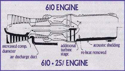
Propulsion
Figure 11: Engine envisaged for Concorde B.
The suggestion was to create an engine, based on the Olympus, with a 0.25
bypass ratio, by introducing a new, low-pressure spool (compressor and turbine)
and eliminating the afterburner. The reduction in specific consumption in cruise
was estimated at 2.8 %, and even more in take-off, climb and holding. The
increase in the weight of the propulsion units was put at 5,098 kg, i.e. 28 % of the
initial weight.
Other modifications
The introduction of composite materials would have enabled a reduction in
airframe weight of 1,088 kg.
This aircraft was never built.
36Summary
5 FUTURE SUPERSONIC
TRANSPORT AIRCRAFT (ATSF)
After discontinuing production and abandoning the Concorde programme,
Aerospatiale maintained a small team of engineers to capitalise on expertise
accumulated over more than 20 years in all aircraft definition disciplines (79,000
hours of wind tunnel and computing resources important for aerodynamics in
particular, tests in all kinds of laboratories and ultimately more than 5,000 hours
of flight tests). The goal of this team was to define the characteristics of a new
supersonic aircraft, in particular its weights, taking into account technological
developments (introduction of composites) and the certification requirements of
the moment.
Overall enhancement of the aircraft would depend on significant improvements in
L/D ratio, specific fuel consumption of propulsion units, materials and weights 2.
Improving aerodynamic L/D ratio
Improvement in the L/D ratio was mainly obtained (Figure 12) by a reduction in
the area of the cross sectional area of the fuselage relative to that of the wing and
by an increase in the aspect ratio, from 1.8 to 2.2 or 2.7 for later projects. The
wetted surface area subject to friction decreased from 3 to 2.7 times the wing
area.
2. Source:“L’avion de transport à grande vitesse ATSF – AGV”, 2009 by Jean Marqueze-Pouey
(former head of the Pre-projects and Research department of Aerospatiale’s Aircraft division).
38Summary
AAE DOSSIER No.46 NEW SUPERSONIC AIRCRAFT PROJECTS
Figure 12: Evolution of supersonic designs 1980-2000 (WS: wingspan;
WA: wing area; aspect ratio: WS2/WA).
The external width of the fuselage was increased to accommodate four passengers
per row in “business class” and five in “economy class”, but was limited to 3.49 m
(Concorde 2.88 m and A320
3.9 m).
The fuselage width/wingspan
ratio was therefore reduced from
0.1125 for Concorde to 0.0956
for the ATSF (Figure 13).
The introduction of a variable-
section fuselage, satisfying
“coke bottle shaping” area rule
considerations (to minimise
wave drag and interference drag
between the fuselage and the
wingspan), was studied but
rejected. The Boeing pre-project
(HSCT) had also considered it at
this time.
Figure 13: Commercial layout and cabin width.
“In all, the combination of these (aerodynamic) alterations brings the cruising L/D
ratio (at supersonic speed) of the ATSF to 10.2, as against 7.3 for Concorde.”
(Science & Vie No.858, March 1989: “SuperConcorde à la rescousse”).
In addition, the introduction of leading edge flaps would have improved the
aerodynamic characteristics of take-off, climb and landing.
40Summary AAE DOSSIER No.46 NEW SUPERSONIC AIRCRAFT PROJECTS Improved specific fuel consumption and engine noise For the last forty years, the increase in engine bypass ratio on subsonic aircraft (secondary and primary flow ratio), resulting in reduced jet efflux speeds, has both improved specific fuel consumption and reduced engine noise. For these aircraft, the improved SFC largely offsets the increased weight and external drag of the engines and nacelles. But improvements in propulsive efficiency and fuel consumption decrease as aircraft speed increases, to level out at Mach 2. On the ATSF (1978-1980), a parametric study was conducted by Aerospatiale and SNECMA using the characteristics of four engine projects of the same technological level, with bypass ratios of 0.0, 0.46, 0.73 and 1.14 at take-off: the same component performances and internal temperatures were used with adapted dimensions and weights. Similar studies were carried out at Rolls-Royce. After optimising range and payload the “best aircraft”, i.e. those with the lowest take-off weight and fuel consumption, were those fitted with an engine with a very low bypass ratio, under 0.46. The slight improvement in fuel consumption in cruise achieved by increasing the bypass ratio did not offset the increase in powerplant weight and drag. Any improvement in fuel consumption compared with the Olympus remained very modest: only a few percent. Those aircraft with optimal performance left noise problems unresolved. Estimated noise levels, even without the necessary margins for error, were higher than the regulatory limits in force at that time (Chapter 3: four-engine aircraft, International Civil Aviation Organization Annex 16). Since then, Chapter 14, applying to all aircraft with a take-off weight above 55 t, requires an additional reduction of 17 EPNdB in cumulative noise. There was therefore an incompatibility between efficiency and noise requirements for a conventional engine (single or double core). A “variable cycle” engine appeared necessary in order to reconcile the conflicting requirements of the mission: double core engine at take-off and initial climb, and single core during supersonic cruise. At that time, during 1980-1995 in Europe, Rolls-Royce and SNECMA were each studying solutions with ancillary compressors (1993). Two solutions were considered. Rolls-Royce was planning two fans placed one behind the other (Tandem Fan System), SNECMA was considering concentric fans around a single core turbojet (Mid fan system, MCV 99 project). Figure 14 illustrates this concept. The choice between the two concepts was to be based on a comparison of the effects of the increase in friction drag and weight associated with larger air intakes, nacelles and nozzles, on the one hand, and the impact of the increase in wave drag linked to a larger cross sectional area on the other. 42
Summary

AAE DOSSIER No.46                      NEW SUPERSONIC AIRCRAFT PROJECTS

Figure 14: Example of a variable cycle engine.
In subsonic mode, the opening of an auxiliary air inlet enables an increase of secondary
flow and a bypass ratio of the order of 2 with jet speeds of around 400 m/s in static mode,
and 500 m/s at Mach 0.3. In cruise the bypass ratio dropped to about 0.7. This propulsion
unit would have been heavier and less efficient in cruise than a conventional engine with
a bypass ratio of 0.7.
Assuming that it was possible to build such an engine (less efficient than a conventional
engine for each flight phase with a much more complex nacelle) and to achieve
acceptable weights and efficiency, the resulting propulsion unit would have enabled at
best a noise reduction of 15 to 20 dB at take-off, according to one of the team leaders
into supersonic engine research at the time at SNECMA: i.e. 40 to 50 EPNdb in all over
the 3 points, as compared to Concorde.
This level would still have exceeded the limits set in Chapter 14 by about 20 EPNdb, and
would have been higher by some 30 to 40 EPNdb than most recently certified aircraft.
The development of such a type of engine, with the proposed features and a level of
reliability acceptable for the civilian market, in other words “enabling a 80% improvement
in lifespan compared to the Olympus [...] would require a development time estimated at
15 years and a high level of investment” (SNECMA, Essor des Marchés Civiles,
1986-1996).
The engine manufacturers halted these feasibility studies at that point.

Development costs and cost price
During a study day in 6 April 2000 at ONERA, the main conclusions of which are to be
found in AAE’s Dossier 19, a presentation was made of the costs of developing a
long-range supersonic transport aircraft (ESCT), assessed by industrialists in 1997 at
$ 17.4 billion for the airframe alone. Development of the engines and of derivative
versions of the aircraft would have led to an overall cost of $ 25 to $ 30 billion. For 400
aircraft, the cost per aircraft would have been $ 350 million, including $ 150 million
needed to amortise development costs. After taking into account inflation, these
development costs would today represent respectively between $ 37 and $ 45 billion.
The cost price would be $ 525 million, including $ 225 million per aircraft for development.
In comparison, the list price of the A380 is in the order of $ 428 million.

  44
Summary
6 NOISE DURING CRUISE,
SONIC BOOM
A cruising supersonic aircraft produces a sonic “boom” or more precisely an
overpressure locally on the ground between the Mach cones generated by the
nose and the rear of the aircraft. This overpressure caused certain damages and
resulted in overflight being banned over inhabited land.
Many studies are underway, mainly in the United States, to reduce this
overpressure on the ground. There would seem to be two approaches:
• aerodynamic shape that would limit this noise to an acceptable level up to Mach
1.4-1.5: QueSST, a prototype of which is described below;
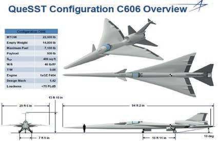
Figure 15: QueSST demonstrator configuration C606.
46Summary AAE DOSSIER No.46 NEW SUPERSONIC AIRCRAFT PROJECTS • use of a limited Mach number, from 1.1 to 1.2, combined with atmospheric tempe- rature gradients with shock wave refraction phenomena above the ground to absorb noise: solution adopted for the Aerion project (see § 4.4). The actual speed obtainable over inhabited land would therefore be significantly lower than Mach 2. The demonstrator in Figure 15, designed to fly at Mach 1.42, has a length of 28.7 m for a wingspan of 9 m, a maximum exterior fuselage width of less than 1 m, an aspect ratio of 1.37 and a wetted surface area/wing area ratio greater than 3.7. These characteristics will not improve the aerodynamic properties at either low or high speeds and will lead to very high take-off and landing speeds (10° attitude on take-off!). In addition to optimising the aerodynamic profiles, the aircraft under study demonstrate a slow evolution of the front fuselage section then an evolving fuselage section in order to offset the enlargement of the front section induced by the presence of the wingspan (area rule). An article published on the NASA website on 8 May 2012 indicated that a 244 m fuselage would be needed for an aircraft carrying 30 to 80 passengers (3 or 4 abreast?): “Unfortunately, while an 800-foot-long airliner may lead to publicly acceptable sonic booms, an aircraft that size still must fit at its gate, make turns while taxiing to the runway without hitting anything and generally not require an expensive redesign of the nation’s airports.” But what would be the dimensions, weight and L/D ratio of an aircraft capable of carrying 12 to 18 passengers, with a width of around 2 m and ten meters long, if the outer section of the fuselage is to obey the area rule? 48
Summary

7        SUPERSONIC BUSINESS
         AIRCRAFT

A number of supersonic aircraft projects, mainly business jets, are being proposed
to a wealthy clientele by “start-ups” with no industrial past in aeronautics. They
hope that the size of aircraft, smaller than Concorde, will reduce environmental
impact, especially noise.

Use of business jets

Figure 16: Use of business jets (source: Executive Controller, January 2017).

 50
Summary AAE DOSSIER No.46 NEW SUPERSONIC AIRCRAFT PROJECTS An analysis of the resale market of more than 300 business aircraft, illustrated in Figure 16, shows that these aircraft have an average use of around 350 hours a year, regardless of their price and manufacturer. The latest aircraft to be delivered meet environmental standards for CO2 and acoustic requirements stipulated in Chapter 14. This low level of use means it would be difficult to offset the costs of a development programme for a new supersonic aircraft (and not a derivative one, as is the case currently). It also limits the sales of spare parts and equipment, the main source of revenue for OEMs, engine manufacturers in particular. For information, the Gulfstream G650 can already carry eight passengers over 7,000 NM (12,964 km) at Mach 0.85 in a cabin 2.59 m wide and 14.26 m long, or 19 passengers over shorter distances. European project: HISAC From 2005 to 2009, a European “High Speed Aircraft” research project investigated the feasibility of a supersonic 8-passenger aircraft. This programme included 37 partners and was tasked with defining a high-tech product that was both economically viable and respectful of environmental criteria. Three types of aircraft were considered (figure 17) by three teams of European aircraft manufacturers (HISAC-T-6-26-1 of 21/07/2008), each giving priority to one of the criteria below: • project A: minimum weight and noise; • project B: maximum range; • project C: limited sonic boom. Figure 17: European HISAC project. 52
Summary

AAE DOSSIER No.46                     NEW SUPERSONIC AIRCRAFT PROJECTS

Figure 18 summarises the results of these studies: Since the configurations of the
three aircraft types seem to have changed during the project, it can be assumed
that the images and figures indicated correspond to the last studies.

    Figure 18: The three HISAC families (Source: DLR).
The specific fuel consumption of the engines (SFC) of the three families was
respectively estimated at 1 kg / daN.h (project A) and 0.97 kg / daN.h (project B) at
Mach 1.6, and 1.09 kg / daN.h (project C) at Mach 1.8. Few details are available on
their thermodynamic design and cycles. We may note the very slight improvement on
Concorde in terms of the lift-to-drag ratio (L/D).
The aerodynamic and propulsive characteristics of these aircraft led to specific ranges
“VxL/D / SFC” very close to that of Concorde at Mach 2, which would surely have been
lower once manufacturing constraints and parasitic drag (antennas, ventilation
sockets...) had been taken into account. Although the fuel reserves recommended by
the NBAA (National Business Aviation Association) are under half those required by
regulations for commercial aircraft, the maximum range and empty weights listed
above would have been very difficult to reach, especially for aircraft B and C.
In addition, the civil certifiability of these projects, particularly with respect to the
position of the propulsion units, would have had to be verified before any launch. The
transition of such an entirely new aircraft from “pre-pre-project” stage to production
stage was likely to have increased the empty weights and therefore the take-off
weights, as illustrated by the Concorde experiment, which went from a MTOW of 115 t
to one of 185 t for the same mission.
This European research programme was discontinued because the goal of
designing an economically viable aircraft that met with environmental criteria
was out of reach.

 54
Summary
AAE DOSSIER No.46 NEW SUPERSONIC AIRCRAFT PROJECTS
New aircraft proposed
The information presented in italics or in bold is directly taken from the manufacturers’
websites.
Aerion long-range (LR) cruise at Mach 1.6, reduced to 1.4
From 2007 to 2017, three Aerion aircraft projects were proposed: Figures 19 to 21
below illustrate the main features.
Max take-off weight 40.8 t
Engines 2 JT9D-219 engines
Length 41.3 m
Wingspan 19.6 m
PAX 8-12
Cabin width 1.9 m
Figure 19: Aerion SBJ project. Max operating speed Mach 1,6
© Aerion
Range 4,200 NM (7,780 km) at Mach 1.4
List price $80 million
Development cost $2 to $3 billion
Certification - 2007 forecast: TBD,
- 2014 forecast: 2021
Entry into Service - 2007 forecast: 2017-2018
- 2014 forecast: 2022
The range and fuselage diameter must not have satisfied the potential clientele
since a new version was put forward in 2014:
Max take-off weight 52.1 then 54.9 t
Engines 3 engines
Length 49 then 52.1 m
Wingspan 21 then 18.6 m
Figure 20: Aerion AS2 project. PAX 8-12
© Aerion
Cabin width 2.2 m
Max operating speed Mach 1.6
Range 4,750 NM (8,780 km) at Mach 1.4
List price $100 then $120 million
Development cost $4 billion
First flight 2018-2019 with EIS 2023
56Summary
AAE DOSSIER No.46 NEW SUPERSONIC AIRCRAFT PROJECTS
The range and cabin width were increased at the cost of a significant rise in
take-off weight. The two JT8D-219 engines were replaced by three engines, to be
defined.
Finally, a new definition was published on 15 December 2017:
Max take-off weight 60.3 t
Engines 3 GE engines, to be defined
Length 51.8 m
Wingspan 23.5 m
PAX 8-12
Cabin width 2.2 m
Max operating speed Mach 1.6
Figure 21: Aerion AS2 project.
© Aerion Range 4,200 NM (7,780 km) at Mach 1.4
List price $120 million
Development cost $4 billion
First flight 2023 with EIS 2025
Aerion is proposing a laminar wing (tried many times on subsonic aircraft without
success) to justify the announced performances. The HISAC programme had
proposed the introduction of a laminar wing and empennage for its “long-range
configuration” (§ 5.2). The estimated L/D ratio was 7.45.
To sum up, to carry eight passengers over 4,200 NM in the absence of wind:
• Expected Entry Into Service date for Aerion has been extended by eight years
• Three engines are needed today, two of which under the wings, instead of two
at the rear
• Take-off weight has increased from 40.8 t to 60.3 t
• No information is provided as to empty weight
• Fuel consumption is over 3 tonnes per passenger.
The final versions will apparently have a cruising Mach number of 1.4 over uninhabited
areas and 1.1 over inhabited areas. The range in the latter case would be about
1,000 NM less than that obtained over the sea, i.e. 4,200 NM over sea and 3,200 NM
over inhabited areas, as against more than 6,500 NM for long-range subsonic
business jet.
The time savings as indicated on the Aerion website (Figure 22) would therefore
be between 12 and 25% per trip, with additional stopovers. The time saved varies
according to the length of stage, the presence of inhabited areas and the need to
divert from the optimal mission for refuelling.
GE Affinity engine: October 2018
GE has presented the results of the propulsive unit studies it carried out for
Aerion. The engine, with 18,000 lbs of thrust (8,006 daN), would use the
58Summary AAE DOSSIER No.46 NEW SUPERSONIC AIRCRAFT PROJECTS Figure 22: Time savings promised by Aerion. compressor, combustion chamber and turbine of the high-pressure spool of the CFM56-5B and 7B which have equipped the A320 and B737 since 1993, substituting a new low-pressure spool with a fan diameter of 1.33 m for a bypass ratio of 3.1. It would be fitted into a nacelle comprising a fixed air intake and variable nozzle. Figures 23 and 24: GE Affinity Engine, Aerion and Aviation Week website. Thrust at 50,000 ft would be 3,500 lbs (1,556 daN). Fuel consumption at Mach 1.4 would be of 0.92-0.95 kg / daN.h (depending on the installation losses) i.e. 1.5 times that of the CFM56-5B at Mach 0.78. The efficiency of the air intake, in particular, at Mach 1.4 would be less than for subsonic aircraft (0.98 as against 0.997). No information is given on the weight of the propulsion system, which can be expected to exceed 3,000 kg. The ejection speed of the mixed flow, close to 350 m/s at take-off, is considered to be borderline if an aircraft is to be eligible for Chapter 14 (probability of success of 50%). Aerion has not released updated AS2 specifications to take into account the characte- ristics of this engine. 60
Summary

AAE DOSSIER No.46                    NEW SUPERSONIC AIRCRAFT PROJECTS

Spike S-512, long-range cruise at Mach 1.6 (see main specifications
in Figures 25 and 26)
A first proposal was made in 2014 to EAA AirVenture Oshkosh airshow, quickly
replaced in 2015.

                                   Max take-off weight                36.2 t
                                   Engines                     2 JT9D-219 engines
                                   Length                              40 m
                                   Wingspan                           19.6 m
                                   PAX                                12-18
                                   Cabin width                         2m
                                   Max operating speed              Mach 1.8
Figure 25: Spike S-512 (2014).
                                   Range                 4,000 NM (7,400 km) at Mach 1.6
                                   List price                    $60 to 80 million
                                   Development cost                     ?
                                   First flight                    2018, EIS?

This proposal, also considered unattractive (range, cabin width), was replaced in
2015. The new one has the following characteristics:

                                   Max take-off weight                52.2 t
                                   Engines                          2 engines
                                   Length                            40.8 m
                                   Wingspan                          17.7 m
                                   PAX                                12-18
 Figure 26: Spike S-512 (2015-
                                   Cabin width                        2.7 m
 2017).
                                   Max operating speed              Mach 1.8
                                   Range                 6,200 NM (11,500 km) at Mach 1.6
                                   List price                      $100 million
                                   Development cost                     ?
                                   First flight                    2023, EIS?

Range was increased by more than 50% and take-off weight went up from 36.2 to
52.2 tonnes. The cruise Mach would slightly reduce fuselage skin temperatures
compared to Concorde. The maximum cruise speed of Mach 1.8 requires
propulsion systems with variable air intake and nozzle. An initial engine was
abandoned without any indication of the architecture of the current one, if it exists.
No development cost is available.

 62
Summary
AAE DOSSIER No.46 NEW SUPERSONIC AIRCRAFT PROJECTS
Comparison with the Aerion: 50% longer range, 12.5% higher long-range cruising
speed, 15.5% lower take-off weight and engines that cannot be bettered. On the
technical side, this project presents challenges that are probably impossible to meet.
Boom: cruise Mach 2.2 (figure 27)
Construction of this aircraft would be preceded by a demonstrator: the “Baby-Boom”
XB1.
“Three engines, delta wing, 45 to 50 passengers, 18 m wingspan, 51 m length, its price
would be $200 million 2016 excluding cabin options. A noise level better than chapter 4.”
Boom is also hoping for changes in the certification process that would, it seems, save
at most a few EPNdBs.
The ticket price has already been published ($2,500 for a one-way ticket) as has the time
to go from London to New York (3:15) but no information has been given by Boom on its
official website as to cabin dimensions, engine thrust and the characteristic weight of this
aircraft.
For example, the only take-off weights available in open literature range from 77,200 kg
in a Flight Global article to 120,000 kg on the “Military-factory” website, updated in May
2017.
It will apparently be equipped
with “3 X non-afterburning
medium bypass turbofans,
proprietary variable geometry
intake and exhaust, Boom has
not released a thrust specification,
but Blake Scholl (CEO of Boom)
confirms that 15,000-20,000 lb
(6672-8896 daN) thrust for each
engine is in ‘the right ballpark’”
(Flight Global, 5 December 2017).
Figure 27: Boom: the model (above), and the “Dream team”, contrasting with
the hundreds of engineers required to pre-develop an aircraft!
64Summary
AAE DOSSIER No.46 NEW SUPERSONIC AIRCRAFT PROJECTS
Baby Boom XB1
Boom was planning “to fly a Boom demonstrator in 2017 on a scale of 1/3 (?) carrying 2
crew members, powered by 3 GE J85-21 (CJ610) with 1,560 daN unit thrust, no
afterburners. This aircraft will have a wingspan of 5.2 m for a length of 20.8 m and a
take-off weight of 6.12 t, and will reportedly reach Mach 2.2 and have a range of
approximately 1,000 NM (1,852 km)”. The three engines were initially to be fed by two air
intakes (Figure 28).
The first flight has been delayed twice:
• Mid-2017: the first flight was put back from the end of 2017 to the end of 2018 after the
addition of a third air intake above the fuselage (figures 28);
The central engine
was initially fed by
the two air intakes in
violation of the basic
rules of segregating
propulsion units.
Figure 28 : First Baby
Boom XB1.
Figure 28 b-c: Baby Boom XB1 mid-2018.
66Summary AAE DOSSIER No.46 NEW SUPERSONIC AIRCRAFT PROJECTS • July 2018: it was put back once more to late 2019 to optimise aerodynamics and change the engine, with the adoption of a variant of the GE J85, the smaller diameter GE J85-15 (with a maximum thrust without afterburner of 2,925 lbs (1301 daN). Used at the maximum thrust levels certified for GE J85-21 (or GE J85-15), the XB1 will be over-powered at take-off – with a thrust MTO/MTOW ratio of 0.76 (0.633) dan/kg compared with 0.37 for Concorde – and even more so in cruise. This should enable it to take off and fly in supersonic mode, albeit with very poor aerodynamic characteristics, as long as this is permitted by its flight qualities and powerplant integration (two types of air intake for the tail engine and underwing engines), which represented 10 years’ work for Concorde (see Appendix 2: ‘Architecture of the propulsion system’). Why do the engines have such high installed thrust? • Is the intention to take off at reduced thrust in order to minimise jet efflux speed and noise? • The Northrop F-5E / F Tiger II aircraft uses this engine at a maximum Mach of 1.63 with a compressor intake temperature of 350°K (+77°C) in ISA + 5°C, compared with the 440°K (+167°C) at Mach 2.2 required at altitudes above 11 km for the Baby Boom. How much thrust reduction will be necessary to maintain acceptable compressor exhaust and turbine intake temperatures? Given the over-powering, a reduced level of thrust might allow for supersonic cruise. The same question will arise for internal pressures. No information was found on the other characteristic weights of this aircraft... What do the promoters of this project wish to demonstrate with the Baby Boom? • Maybe they intend to take off at adapted thrust (~ 50% of take-off thrust) to make less noise? With the hope that an engine manufacturer will be able to design and manufacture an engine with a bypass ratio that reproduces this jet speed, and to integrate it into a propulsion system which has the correct weight, drag and fuel consumption in cruise to achieve the desired overall performance. • The final engine, if it exists, will be very different from the J85-21 and J85-15. In particular, its changing airflow in the course of the flight will require specific integra- tion. This will involve redefining air intakes and their management, one of the most tricky areas of Concorde development. Summary of the proposals Figure 29 gives the main characteristics of these different projects, as reported in November 2017, showing the desire to obtain ranges significantly higher than Concorde. 68
Summary

AAE DOSSIER No.46                      NEW SUPERSONIC AIRCRAFT PROJECTS

                                     Concorde            Boom               Aerion      Spike 2
                                                                           dec. 2017
 Number of passengers                  100               45-55               8-12       12-18
 Cruise Mach                            2                    2.2              1.4         1.6
 Reference Wing Area    (m2)           358                218                160         164
 Length (m)                           61.66                  51              51,8         37
 Wingspan (m)                          25.6                  18              23.5        17.7
 Range (without refuelling) NM        3,500              4,500              4,200       6,200
 Take-off weight (kg)                185,080        77,200 / 120,000        60,328      52,153
 Estimated manufacturer’s          75,500-76,000             ?              32,228      21,432
 empty weight (kg)

Figure 29: Concorde and summary of proposed projects.
Aerodynamics
Comparison of the main aerodynamic characteristics taking into account the accuracy
of the measurements on the photos or diagrams:
                                        Concorde       ATSF        Boom      Aerion     Spike 2
                                                                            dec. 2017
 Cruise Mach                                  2          2          2.2        1.4        1.6
 Reference Wing area WA (m2)                 358        755        218        161.5       164
 Wingspan WS (m)                            25.6       41-42        18        23.5        17.7
 Estimated aspect ratio                     1.83       2.34        1.49       3.42        1.92
 (WS2/WA)
 Relative wing thickness               3% / 2.15%
 root → tip                              1.82%
 Master cross-section area /                0.020      0.013       0.032      0.030      0.038
 wing area
 Wetted surface area / wing area            2.98       2.69        3.33       4.04        4.00
 (excluding engines)
 Wing sweep internal angle                    17        19         19.8        71          24
Figure 30: Concorde and aerodynamic characteristics of proposed projects,
(green = improvement / red = deterioration).
Compared to Concorde, the new projects have significantly larger fuselages (the
passengers have to be accommodated after all!) and a greater ratio of wetted surface
areas compared to wing characteristics. This goes against goals set for pre-projects
studied by the European manufacturers (Aerospatiale, British Aerospace...) at the end
of the last century to improve the lift-over-drag ratio of the aircraft.
An assessment of L/D ratios, according to traditional methods for pre-projects, gives
the following results:
        L/D ATSF > L/D Concorde ~ L/D Aerion > L/D Spike > L/D Boom.

 70
Summary
AAE DOSSIER No.46 NEW SUPERSONIC AIRCRAFT PROJECTS
Note that the L/D ratios estimated for the European HISAC research programme
(Figure 21), for projects close to the Aerion and Spike 2, are between 7 and 7.74
at the “very preliminary stage”.
Moreover, these business jets did not incorporate sonic boom attenuation
requirements that would have significantly deteriorated the L/D ratio (L/D QueSST
< L/D Boom).
Weights
The use of new materials, particularly composites, is intended to significantly lighten
the structural parts of these new projects. It should be noted that such elements
represent only a part of the empty weight of aircraft. For Concorde, for instance, the
weights of the wings, empennage and fuselage represent only 35% of the empty
weight. Moreover, experience shows that the weight savings afforded by composite
materials decrease with the size of the aircraft: not only does the need to ensure
electrical continuity require the addition of metal elements, it is also more difficult to
manufacture small parts with complex shapes using composites than with metal alloys.
Figure 31: Comparison of the characteristic weights of Concorde with
the proposed projects.
These new aircraft will need to take into account regulatory design requirements
introduced in the last 60 years, more stringent than those governing Concorde,
thereby leading to an increase in weight.
The relative weight of an aircraft increases as its size (floor area) decreases. For
example, a subsonic business jet with a floor area of 20 m 2 has an OEW / floor
area ratio approximately 50% greater than that of a 100 m 2 aircraft.
72You can also read