Dell EMC PowerMax: Family Overview - Abstract - Dell Technologies
←
→
Page content transcription
If your browser does not render page correctly, please read the page content below

Technical White Paper

 Dell EMC PowerMax: Family Overview
                         Abstract
                         This document provides an overview of the Dell EMC™ PowerMax family, an
                         NVMe-based, mission-critical data storage offering. It details the theory of
                         operation, packaging, and features which make PowerMax an ultra-performing,
                         all-flash storage product.

                         September 2020

H17118.2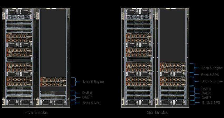
Revisions

Revisions
                  Date                         Description

                  April 2018                   Initial release

                  October 2018                 Updated for 5978 Service Release

                  September 2019               Incorporated major Q3 2019 platform updates

                  September 2020               Incorporated major PowerMaxOS Q3 2020 platform updates

Acknowledgments
               Author: James Salvadore

The information in this publication is provided “as is.” Dell Inc. makes no representations or warranties of any kind with respect to the information in this
publication, and specifically disclaims implied warranties of merchantability or fitness for a particular purpose.

Use, copying, and distribution of any software described in this publication requires an applicable software license.

Copyright © 2018–2020 Dell Inc. or its subsidiaries. All Rights Reserved. Dell, EMC, Dell EMC and other trademarks are trademarks of Dell Inc. or its
subsidiaries. Other trademarks may be trademarks of their respective owners. [11/2/2020] [Technical White Paper] [H17118.2]

2         Dell EMC PowerMax: Family Overview | H17118.2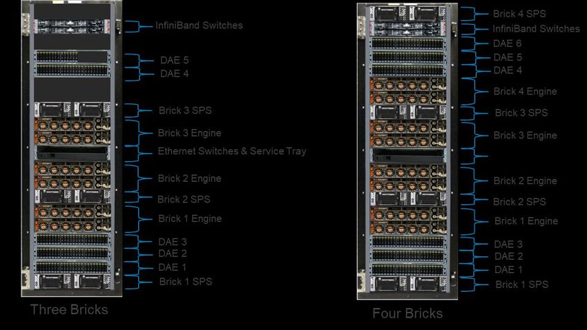
Table of contents

Table of contents
    Revisions.............................................................................................................................................................................2
    Acknowledgments ...............................................................................................................................................................2
    Table of contents ................................................................................................................................................................3
    Executive summary.............................................................................................................................................................5
    1     Introduction ...................................................................................................................................................................6
          1.1      Primary PowerMax benefits................................................................................................................................6
          1.2      PowerMaxOS Q3 2020 release ..........................................................................................................................7
          1.3      Terminology ........................................................................................................................................................8
    2     PowerMax overview ...................................................................................................................................................11
          2.1      Background.......................................................................................................................................................11
          2.2      The PowerMax family .......................................................................................................................................11
    3     PowerMax architecture overview ...............................................................................................................................12
          3.1      Designed for NVMe ..........................................................................................................................................12
          3.2      Expandable modular architecture: PowerMax Brick.........................................................................................12
          3.2.1 Engines .............................................................................................................................................................13
          3.2.2 Drive array enclosures ......................................................................................................................................16
          3.2.3 Drive options and configurations ......................................................................................................................16
          3.2.4 Flash optimization .............................................................................................................................................26
          3.2.5 Director slot layout and connectivity options ....................................................................................................28
    4     Reliability, availability, and serviceability ....................................................................................................................32
    5     PowerMax Data Services ...........................................................................................................................................34
          5.1      Advanced Data Reduction ................................................................................................................................34
          5.1.1 Data reduction using the Adaptive Compression Engine .................................................................................34
          5.1.2 Data reduction using inline deduplication .........................................................................................................35
          5.2      Enterprise Grade Security ................................................................................................................................35
          5.3      Remote replication with SRDF .........................................................................................................................36
          5.4      Local replication with TimeFinder SnapVX .......................................................................................................37
          5.5      Cloud Mobility for Dell EMC PowerMax ...........................................................................................................38
          5.6      PowerMaxOS Quality of Service features ........................................................................................................39
          5.7      Consolidation of block and file storage using eNAS.........................................................................................39
          5.8      Non-Disruptive Migration ..................................................................................................................................40
          5.9      Embedded Management using Unisphere for PowerMax ................................................................................41
          5.10 Advanced data analytics with CloudIQ .............................................................................................................41
          5.11 PowerMax storage integration with IT automation tools...................................................................................42

3            Dell EMC PowerMax: Family Overview | H17118.2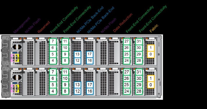
Table of contents

        5.11.1       PowerMax Plugins for VMware vRealize Orchestrator ................................................................................42
        5.11.2       VMware vRealize Automation ......................................................................................................................42
        5.11.3       Ansible Modules for PowerMax....................................................................................................................42
        5.11.4       Docker, Kubernetes, and the Container Storage Interface driver specification ...........................................43
    6   Streamlined software packaging ................................................................................................................................44
    7   PowerMax system deployments.................................................................................................................................46
        7.1      PowerMax 2000 system configurations ............................................................................................................46
        7.1.1 PowerMax 2000 configurations ........................................................................................................................46
        7.2      PowerMax 8000 system configurations ............................................................................................................47
        7.2.1 Single-rack PowerMax 8000 configurations .....................................................................................................47
        7.2.2 Dual-rack PowerMax 8000 configurations ........................................................................................................48
        7.3      Dell EMC PowerOne with PowerMax ...............................................................................................................50
    8   Summary ....................................................................................................................................................................51
    A   Technical support and resources ...............................................................................................................................52
        A.1      Related resources ............................................................................................................................................52

4          Dell EMC PowerMax: Family Overview | H17118.2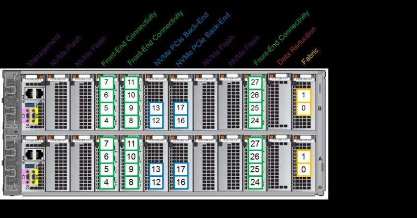
Executive summary

Executive summary
           The Dell EMC™ PowerMax family is the first Dell EMC hardware platform that uses an end-to-end Non-
           Volatile Memory Express (NVMe) architecture for customer data. NVMe is a set of standards which define a
           PCI Express (PCIe) interface used to efficiently access data storage volumes based on Non-Volatile Memory
           (NVM) media, which includes modern NAND-based flash along with higher-performing Storage Class Memory
           (SCM) media technologies. The NVMe-based PowerMax was specifically created to fully unlock the
           bandwidth, IOPS, and latency performance benefits that NVM media offers to host based applications which
           are unattainable using the previous generation of all-flash storage arrays.

5      Dell EMC PowerMax: Family Overview | H17118.2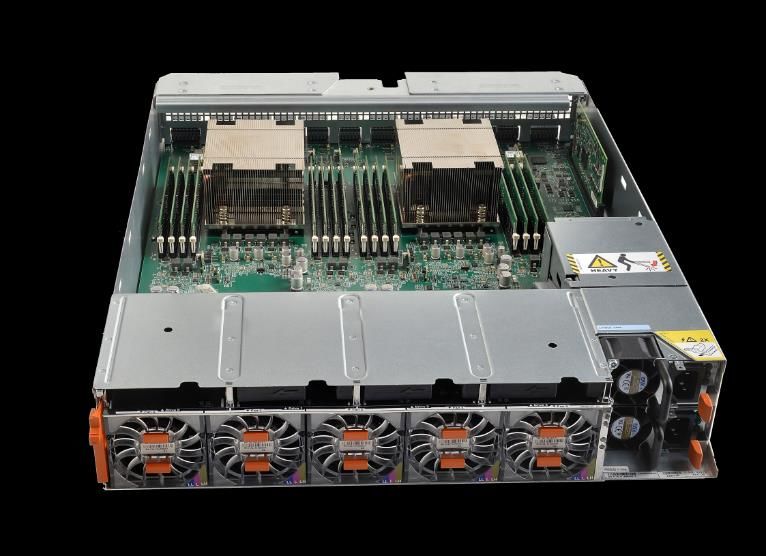
Introduction

1              Introduction
               The Dell EMC PowerMax family offers unprecedented levels of performance and scale using next-generation
               Storage Class Memory (SCM) and high-speed SAN infrastructures. PowerMax is powerful, simple, and
               trusted storage without compromise. It is built for mission-critical apps of today and tomorrow with end-to-end
               NVMe, next-gen storage media (SCM), real-time machine learning and inline deduplication and compression,
               while also delivering the features and data services businesses require.

1.1            Primary PowerMax benefits
               The primary benefits that PowerMax platforms offer to customers include the following.

                   •   A powerful end-to-end NVMe storage architecture that delivers:

                       -   Up to 15M IOPS, 350 GBps throughput (187 K IOPS per rack unit)
                       -   Industry-standard NVMe-Based flash and SCM drives
                       -   Native NVMe Drive Array Enclosures (DAEs)
                       -   Large-scale workload consolidation in which Open Systems and mainframe block storage can co-
                           exist with file storage on the same platform

                   •   Integrated, real-time machine-learning engine for automatic data placement

                       -   Automated I/O recognition and data placement across flash and SCM media to maximize
                           performance with no management overhead
                       -   Elimination of high-performance silo and consolidation of all mission-critical workloads and
                           secondary applications

                   •   Enterprise grade storage security and protection

                       -   End to end efficient data Encryption
                       -   FIPS 140-2 validated Data at Rest Encryption (D@RE)
                       -   Secure snapshots, role-based authentication, and tamper-proof audit logs

                   •   Enterprise levels of reliability with proven six-nine’s availability in a single array

                   •   Investment protection with the Future Proof Program

                   •   Global inline data deduplication and enhanced compression with virtually no performance impact

                       -   Works with all data services
                       -   Provides a 3.5:1 data reduction guarantee through Dell’s Future Proof Program (some text)

                   •   Powerful data services which help protect, manage, and move customer data on the array. These
                       data services include remote replication with SRDF, High Availability with SRDF/Metro, Local
                       replication with TimeFinder SnapVX, and Cloud Mobility

                   •   A comprehensive easy to use API covering storage provisioning, all configurable data services, array
                       configuration, performance monitoring and alerting.

               Note: For more information about these PowerMax features and their value propositions, see the Dell EMC
               PowerMax Family web page.

6       Dell EMC PowerMax: Family Overview | H17118.2
Introduction

1.2            PowerMaxOS Q3 2020 release
               The newest enhancements featured in the PowerMax Q3 2020 release expand the PowerMax offering by
               adding cloud mobility, data resiliency, enabling SRDF replication for VMware® vSphere® Virtual Volumes™
               (vVols), continuous high availability for SRDF/Metro configurations, and continued security hardening of the
               system. Some of the key features in the Q3 2020 release key features are shown in the table below:

                              Q3 2020 PowerMaxOS release core features
               Q3 2020 PowerMaxOS release core
                                                                    Value proposition and benefits
               feature
               Cloud Mobility for Dell EMC PowerMax                 Extends PowerMax storage to the cloud (public or
                                                                    private) for long-term retention. Snapshots can be
                                                                    shipped to object stores AWS, Microsoft Azure, and Dell
                                                                    EMC ECS.
               VMware vVols replication with SRDF                   Combine the gold standard in storage replication
                                                                    (SRDF) with VMware vVols for mission-critical
                                                                    operations - orchestrated using VMware Site Recovery
                                                                    Manager (SRM)
               SRDF/Metro Smart DR                                  A space and bandwidth efficient metro-aware Disaster
                                                                    Recovery for a SRDF/Metro region.

               Snapshot policies                                    Automated, compliance-based snapshot protection for
                                                                    applications.

               25 GbE I/O module                                    Enhancing the PowerMax Ethernet SAN offerings with a
                                                                    new 4 port 25 GbE I/O module used for iSCSI and
                                                                    SRDF connectivity

               End-to-end efficient encryption                      Provides complete encryption protection when data is
                                                                    written from the host to PowerMax storage media
                                                                    (drives). This solution has the added benefit of
                                                                    incorporating up to 5:1 data reduction resulting in a
                                                                    highly secure, highly efficient offering for our customers.

               IBM Transparent Cloud Tiering (TCT)1                 A licensed IBM function that offloads all data movement
                                                                    processing-related workloads from the mainframe host
                                                                    when moving data to or from cloud repositories.
                       1
                           Supported on PowerMax 8000 only through RPQ process and requires MFE 8.5.

7       Dell EMC PowerMax: Family Overview | H17118.2
Introduction

1.3            Terminology
               This document uses the following PowerMax terminology:

                             Key PowerMax terms and definitions

               Terminology              Equivalent term       Definition

               Automated Data           ADP                   Automated Data Placement is the system’s ability to
               Placement                                      intelligently manage data placement between two different
                                                              drive technologies in the same array.

               DAE24                    DAE24                 DAE24 refers to the drive array enclosure that is used to
                                                              store up to 24 NVMe drives in PowerMax arrays.

               Dell EMC PowerMax        PowerMax 2000         PowerMax 2000 is the entry NVMe scale-out array sold with
               2000                                           the Essentials and Pro software packages.

               Dell EMC PowerMax        PowerMax 8000         PowerMax 8000 is the flagship NVMe scale-out array sold
               8000                                           with the Essentials and Pro software packages.

               Dell EMC PowerMax        PowerMax              The PowerMax family refers to the Dell EMC NVMe-based,
               family                                         mission-critical data storage offering.

               Disk group               Disk group            This is a collection of hard drives sharing the same
                                                              technology, size, and performance characteristics.

               Drive Array              DAE                   DAE refers to the drive array enclosure used to store flash
               Enclosure                                      drives and SCM drives in PowerMax.

               Effective capacity (in   TBe                   This includes the benefits of thin provisioning, inline
               Terabytes)                                     compression, deduplication, and space-efficient copies.

               Essentials software      Essentials            The Essentials package is the default PowerMax software
               package                                        package.

               Flash capacity pack      Flash capacity pack   A flash capacity pack includes NVMe flash drive capacity
                                                              (TBu) that can be added to a PowerMax array.

               Inline compression       Compression           Inline compression refers to the intelligent compression
                                                              technology used with PowerMax arrays.

               Inline deduplication     Dedupe                Inline deduplication (dedupe) refers to the deduplication
                                                              technology used with PowerMax arrays.

               Non-Volatile Memory      NVMe                  NVMe is a command set and its associated storage-interface
               Express (NVMe)                                 standards that specify efficient access to data storage
                                                              devices and systems based on Non-Volatile Memory (NVM).

               NVMe flash drives/       NVMe flash drives     NVMe/PCIe-connected flash drives are the latest flash
               NAND                                           devices used to store capacity in PowerMax arrays.

               NVMe over Fabric         NVMe-oF               NVM Express over Fabrics (NVMe-oF) defines a common
                                                              architecture that supports a range of storage networking
                                                              fabrics for NVMe block storage protocol

8       Dell EMC PowerMax: Family Overview | H17118.2
Introduction

               Terminology           Equivalent term     Definition

               NVMe over Fibre       FC-NVMe             NVMe over Fibre Channel extends the NVMe block storage
               Channel                                   protocol and its benefits over data-center fabrics using high-
                                                         speed Fibre Channel as the fabric transport.

               PowerMax Brick        Brick               A Brick is the building block for a PowerMax array. It includes
                                                         an engine, two DAEs, and a fixed TBu of capacity.

               PowerMax zBrick       zBrick              zBrick is the PowerMax mainframe building block consisting
                                                         of an engine, two DAEs, and fixed TBu of capacity.

               PowerMaxOS 5978       PowerMaxOS          The PowerMaxOS 5978 release supports PowerMax NVMe
                                                         arrays, dedupe, and other software enhancements. It can
                                                         also be installed on legacy VMAX™ All Flash arrays.

               Pro software package Pro package or Pro   The Pro package is a comprehensive software offering sold
                                                         as a PowerMax appliance.

               RAID group            RAID group          This is the minimum quantity of hard drives which comprise a
                                                         specific RAID protection scheme.

               Scale out             Scale out           Scale out refers to adding Bricks to grow performance and
                                                         expansion on PowerMax systems.

               Scale up              Scale up            Scale up refers to adding flash capacity packs to a
                                                         PowerMax array.

               Service level         Service levels      Service levels identify a specific performance tier in
                                                         PowerMax arrays.

               Smart RAID            Smart RAID          Smart RAID provides active/active shared RAID support for
                                                         PowerMax arrays.

               Storage Class         SCM                 SCM is a new hybrid storage/memory tier that has read and
               Memory (SCM)                              write performance characteristics which are significantly
                                                         faster than traditional flash drives

               Storage Resource      SRP                 A Storage Resource Pool (SRP) is a collection of hard drives
               Pool                                      which constitute a specific usable capacity for customer
                                                         application data. Most PowerMax arrays consist of a single
                                                         SRP. An SRP's usable capacity can consist of both NAND
                                                         Flash and SCM disks. Automated Data Placement across the
                                                         SCM and NAND Flash drives within the SRP is managed by
                                                         the internal PowerMax machine learning engine. Each SRP
                                                         is protected by a single RAID protection scheme and can
                                                         provide capacity for FBA, file, and mainframe.
               Unisphere™ for        Unisphere           Unisphere for PowerMax is a user interface that enables
               PowerMax                                  management and monitoring of PowerMax arrays along with
                                                         legacy VMAX All Flash, VMAX3™, and VMAX 1 or 2 arrays.
                                                         Unisphere for PowerMax also provides REST API interface
                                                         for managing and controlling Dell EMC arrays.
               Usable capacity (in   TBu                 This refers to the amount of hard drive capacity available in
               Terabytes)                                the array, taking into account the RAID efficiency of the RAID
                                                         type in use.

9       Dell EMC PowerMax: Family Overview | H17118.2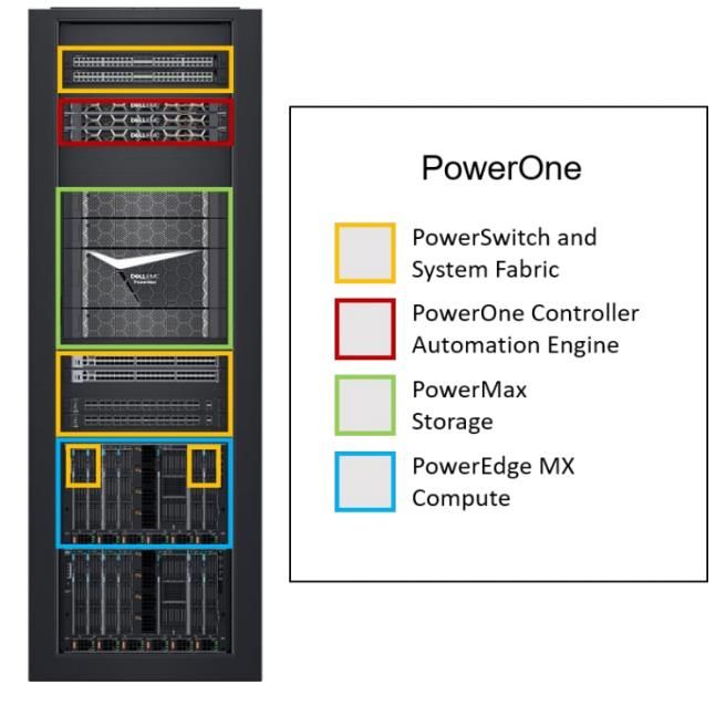
Introduction

               Terminology            Equivalent term      Definition

               zEssentials software   zEssentials          The zEssentials package is the software package sold as a
               package                                     PowerMax appliance for mainframe.

               zFlash capacity pack   zFlash capacity pack A zFlash capacity pack includes NVMe flash drive capacity
                                                           (TBu) that can be added to a PowerMax array for mainframe.

               zPro software          zPro                 The zPro package is the comprehensive software offering
               package                                     sold as a PowerMax appliance for mainframe.

10      Dell EMC PowerMax: Family Overview | H17118.2
PowerMax overview
2 PowerMax overview
2.1 Background
The Dell EMC PowerMax family is built using a 100% end to end Non-Volatile Memory Express (NVMe)
storage architecture, allowing it to reach unprecedented I/O densities and performance by eliminating the
flash media choke points found using traditional SAS and SATA interfaces. The PowerMax opens the door for
customers to deploy innovative applications in the areas of real-time analytics, machine learning, and big data
that demand lower latency and higher performance.
2.2 The PowerMax family
The Dell EMC PowerMax family consists of two models: the PowerMax 2000 and the flagship PowerMax
8000. The PowerMax 2000 is designed to provide customers with efficiency and maximum flexibility in a 20U
footprint. The PowerMax 8000 is designed for massive scale, performance, and IOPS density all within a one
or two-floor-tile footprint.
Both PowerMax arrays have at their foundation the trusted Dynamic Virtual Matrix architecture and internal
system software specifically written for the NVMe platform called PowerMaxOS 5978. PowerMaxOS can run
natively on both PowerMax systems and on legacy VMAX All Flash systems as an upgrade. As with the
previous-generation VMAX All Flash, PowerMax systems are true all-flash arrays – products specifically
targeted to meet the storage capacity and performance requirements of the all-flash enterprise data center.
The PowerMax products are feature-rich, all-flash offerings with specific capabilities designed to take
advantage of ultra-high performing Storage Class Memory (SCM) and higher capacity NVMe flash drives to
create the densest storage configuration possible. PowerMax offers enterprise customers trusted data
services, along with the simplicity, capacity, and performance that their highly virtualized environments
demand, while still meeting the economic needs of more traditional storage workloads. In addition, PowerMax
now allows customers to deploy applications such as real-time analytics, machine learning, and big data that
demand the lower storage latency and higher IOPS densities previously unattainable with legacy all flash
offerings.
PowerMax family
11 Dell EMC PowerMax: Family Overview | H17118.2PowerMax architecture overview
3 PowerMax architecture overview
Although the PowerMax platform uses many of the technologies and data services found in legacy VMAX All
Flash, PowerMax provides customers with a differentiating value as it is designed from the ground up to be
the first platform in the industry to take full advantage of end-to-end FC-NVMe connectivity and emerging data
storage media such as SCM. The following sections detail the key PowerMax architectural value propositions
for customers.
3.1 Designed for NVMe
PowerMax is a technology leader providing a full end-to-end NVMe flash storage architecture for storing
customer data. The PowerMax NVMe architecture provides:
• I/O Density with Predictable Performance – PowerMax has been designed to deliver extreme I/O
density – capable of delivering approximately 187 K IOPS per rack unit (U) or up to 15M IOPS in a
two-rack system (two floor tiles), regardless of workload and storage capacity utilization.
• NVMe Storage Density – Using commercially available, high capacity, dual-ported enterprise NVMe
flash drives, PowerMax delivers outstanding NVMe TB per floor tile. PowerMax support for high
capacity commercially available NVMe flash and SCM drives provides a differentiated capability as
compared to many other all-flash alternatives which use a proprietary flash drive design. This allows
PowerMax to leverage the increases in flash drive densities, performance, economies of scale, and
fast time-to-market delivered by the industry flash drive suppliers.
• Future Proof Design - The PowerMax NVMe design is future proof as it can seamlessly implement
current and future SCM and NAND Flash drive capacities and allow for hosts to connect through
current and future high-speed NVMe-oF SANs.
3.2 Expandable modular architecture: PowerMax Brick
PowerMax configurations consist of modular building blocks called PowerMax Bricks (Bricks). The modular
Brick architecture reduces complexity and allows for easier system configuration and deployment. This
architecture also allows the system to scale while continuing to deliver predictable high performance.
There are two types of Bricks available for PowerMax:
• The open systems Brick supports configurations with Fibre Channel, FC-NVMe, or iSCSI connectivity
with FBA device formatting. The Brick also can be configured for file storage using embedded NAS.
• The mainframe zBrick supports configurations with FICON connectivity and CKD device formatting.
Note: In this document, the term Brick is used when discussing features and functions applicable to both the
open systems and the mainframe. When discussing features specific to mainframe, the term zBrick is
specifically called out.
The initial system Brick includes a single engine consisting of two directors, two system power supplies
(SPS), and two 24-slot 2.5” NVMe Drive Array Enclosures (DAE24) pre-configured with an initial total usable
capacity.
The Brick concept allows PowerMax to scale up and scale out. Customers can scale up by incrementally
adding Flash Capacity Packs. Each Flash Capacity Pack for the PowerMax 8000 has 13 TBu or 15 TBu of
usable storage, and either 11 TBu, 13 TBu, or 15 TBu for the PowerMax 2000 model, depending upon the
RAID protection type selected. PowerMax scales out by aggregating up to two Bricks for the PowerMax 2000,
12 Dell EMC PowerMax: Family Overview | H17118.2PowerMax architecture overview
and up to eight for the PowerMax 8000. Scaling out a PowerMax system by adding additional Bricks produces
a predictable, linear performance improvement regardless of the workload.
Note: For detailed information about available PowerMax Brick configurations, see the PowerMax Family
Specification Sheet.
3.2.1 Engines
The core of the Brick is the engine. The engine is the central I/O processing unit, redundantly built for high
availability. Each Brick consists of:
• Redundant directors that contain multi-core CPUs and memory modules
• Interfaces to universal I/O modules, such as front-end, back-end, InfiniBand, and flash I/O modules
The communication backbone of the Brick is the trusted Dynamic Virtual Matrix Architecture. Fundamentally,
the virtual matrix enables inter-director communications over redundant internal InfiniBand fabrics. The
InfiniBand fabric provides a foundation for a highly scalable, extremely low latency, and high-bandwidth
backbone which is essential for an all flash array. This capability is also essential for allowing the PowerMax
to scale upwards and scale outwards in the manner that it does.
Brick Engine Director
3.2.1.1 Brick CPU core configurations
Each Brick engine has two directors, with each director having dual CPU sockets which support multi-core,
multi-threaded Intel processors. The following table details the engine CPU core layout for each PowerMax
model:
Brick Engine CPU cores
Cores per
CPU
PowerMax model Engine CPU type Brick Max cores per system
cores
Engine
PowerMax 2000 Dual Intel Broadwell, 12 core, 24 48 96 (2 Bricks max.)
2.5 GHz
PowerMax 8000 Dual Intel Broadwell, 18 core, 36 72 576 (8 Bricks max.)
2.8 GHz
13 Dell EMC PowerMax: Family Overview | H17118.2PowerMax architecture overview
The Brick engine uses a core pooling mechanism which can dynamically load-balance the cores by
distributing them to the front end, back end, and data services (such as SRDF, eNAS, and embedded
management) running on the engine. The core pools can be tuned to shift the bias of the pools at any time to
front-end heavy or back-end heavy workloads to further optimize the solution for a specific use case.
Note: Due to the advanced cooling dynamics of the PowerMax engine, the Intel CPUs primarily run in Turbo
mode, providing additional performance capabilities.
3.2.1.2 Brick cache configurations
Every director has 16 memory slots which can be populated with 32 GB and 64 GB DDR4 DIMMS to achieve
up to 1 TB cache per director (2 TB cache maximum per Brick engine).
Brick cache configurations
PowerMax model Cache per Brick Max Cache per system
PowerMax 2000 512 GB, 1 TB, 2 TB 4 TB (2 Bricks max.)
PowerMax 8000 1 TB or 2 TB 16 TB (8 Bricks max.)
On single engine PowerMax 2000 systems, cache is mirrored within the engine across the directors. This is
also true for multi-engine PowerMax 2000 systems and single engine PowerMax 8000 systems. On multi-
engine PowerMax 8000 systems, cache is mirrored across directors in different engines for added
redundancy.
Both the PowerMax 2000 and PowerMax 8000 can support engine configurations with differing cache sizes
(mixed cache). For dual engine PowerMax 2000 models, the system can use engines with different cache
sizes between the engines which are one cache size smaller or larger than the other engine in the system.
For example, cache on engine 1 can be 1 TB while the cache on engine 2 is 512 GB. This would yield a total
cache size of 1.5 TB for the system. Valid mixed cache configurations for the PowerMax 2000 are shown in
the following table:
Supported PowerMax 2000 mixed cache configurations
Number of
Smallest engine cache Largest engine
Bricks in Total system cache
size cache size
system
2 512 GB 1 TB 1.5 TB
2 1 TB 2 TB 3 TB
14 Dell EMC PowerMax: Family Overview | H17118.2PowerMax architecture overview
Mixed cache configurations are available on the PowerMax 8000; but require a minimum of four Bricks or
zBricks in the system. The following table details the supported mixed cache configurations available for the
PowerMax 8000:
Supported PowerMax 8000 mixed cache configurations
Number of
Largest engine Total system
Bricks in Smallest engine cache size
cache size cache
system
4 2 engines at 1 TB 2 engines at 2 TB 6 TB
5 2 engines at 1 TB 3 engines at 2 TB 8 TB
5 3 engines at 1 TB 2 engines at 2 TB 7 TB
6 2 engines at 1 TB 4 engines at 2 TB 10 TB
6 4 engines at 1 TB 2 engines at 2 TB 8 TB
7 2 engines at 1 TB 5 engines at 2 TB 12 TB
7 5 engines at 1 TB 2 engines at 2 TB 9 TB
7 3 engines at 1 TB 4 engines at 2 TB 11 TB
7 4 engines at 1 TB 3 engines at 2 TB 10 TB
8 2 engines at 1 TB 6 engines at 2 TB 14 TB
8 6 engines at 1 TB 2 engines at 2 TB 10 TB
8 4 engines at 1 TB 4 engines at 2 TB 12 TB
Note: Cache within an engine can be upgraded (capacity added), but cache cannot be downgraded (capacity
removed).
3.2.1.3 PowerMaxOS
Each PowerMax engine comes with PowerMaxOS 5978 installed. PowerMaxOS is derived from the trusted
and proven HYPERMAX OS used by the legacy VMAX3 and VMAX All Flash arrays; however, PowerMaxOS
has been re-written to take advantage of NVMe architectures. PowerMaxOS continues to provide industry-
leading high availability, I/O management, quality of service, data integrity validation, data movement, and
data security within an open application platform. PowerMaxOS uses a real-time, non-disruptive storage
hypervisor that manages and protects embedded services by extending high availability to services that
traditionally would have run external to the array. The primary function of PowerMaxOS is to manage the core
operations performed on the array, which include:
• Processing I/O from hosts
• Implementing RAID protection
• Optimizing performance by allowing direct access to hardware resources
• Managing and monitoring the system
15 Dell EMC PowerMax: Family Overview | H17118.2PowerMax architecture overview
3.2.2 Drive array enclosures
Each Brick comes with two 24-slot, dual-ported, 2.5” PCIe NVMe DAEs (DAE24). These DAEs use
redundant, hot-swappable Link Control Cards (LCCs) which provide PCIe I/O connectivity to the NVMe flash
drives. Aside from redundant LCCs, the DAE24 features redundant power supplies with separate power
feeds, providing N+1 power and cooling, resulting in an energy-efficient consumption of up to 25 watts per
drive slot. The DAE24 is 2U high and 19” deep.
Brick NVMe DAE24
The directors are connected to each DAE through a pair of redundant back-end I/O modules. The back-end
I/O modules connect to the DAEs at redundant LCCs. Each connection between a back-end I/O module and
an LCC uses an independent cable assembly. Within the DAE, each NVMe drive has two ports, each of which
connects to one of the redundant LCCs.
The dual-initiator feature ensures continuous availability of data in the unlikely event of a drive management
hardware failure. Both directors within an engine connect to the same drives using redundant paths. If the
sophisticated fencing mechanisms of PowerMaxOS detect a failure of the back-end director, the system can
process reads and writes to the drives from the other director within the engine without interruption.
3.2.3 Drive options and configurations
Both PowerMax 2000 and PowerMax 8000 support 1.92 TB, 3.84 TB, 7.68 TB, and 15.36 TB NVMe flash
drive capacities as well as 750 GB and 1.5 TB SCM drives. All the drive sizes are 2.5” and feature a dual
ported U.2 form factor PCIe interface. These drive capacities can be intermixed on the system.
PowerMax family supported capacity specifications
Array family PowerMax 2000 PowerMax 8000
Capacity and drives
Max Capacity per Array 1.2 PBe 4.5 PBe
(Open)1
Base Capacity per Brick 13.2 TBu3 54 TBu
(Open)
Base Capacity per Brick N/A 13.2 TBu
(mainframe)
Incremental Flash Capacity 13.2 TBu3 13.2 TBu
Packs5
Max Drives per Brick 44 Usable + spare(s) 32 Usable + spare(s)
Max Drives per Array 96 288
16 Dell EMC PowerMax: Family Overview | H17118.2PowerMax architecture overview
Array family PowerMax 2000 PowerMax 8000
NVMe drives
NVMe Drives Supported 1.92 TB, 3.84 TB, 7.68 TB, 1.92 TB, 3.84 TB, 7.68 TB, 15.36 TB
(2.5”) 15.36 TB
SCM drives
SCM Drives Supported 750 GB, 1.5 TB 750 GB, 1.5 TB
(2.5”)
BE Interface NVMe over PCIe NVMe over PCIe
RAID Options Supported RAID 5(7+1) (default) RAID 5(7 +1) (default)
RAID 5(3+1) RAID 6(6+2)
RAID 6(6+2) RAID 1 (Mirrored)4,5
RAID 1 (Mirrored)4,5
a. Max capacity per array based on over provisioning ratio of 1.0
b. 192 drives can be supported in a single cabinet when two systems are packaged in the same rack.
c. 13.2 TBu Brick and Flash capacity pack usable capacities are based on RAID 5 (7+1). 11.3 TBu base capacity and Flash capacity
pack increments possible with RAID 5 (3+1) on PowerMax 2000.
d. RAID 1 will be offered on both PowerMax 2000 and PowerMax 8000 systems post GA of the 3Q 2020 release. Contact your local
Dell Technologies sales team for more details and availability.
e. Incremental capacity packs under RAID 1 are 15.0TBu minimum for both the PowerMax 2000 and PowerMax 8000.
Note: For detailed information about available PowerMax Brick drive configurations, see the PowerMax
Family Specification Sheet.
3.2.3.1 PowerMax Storage Resource Pools overview
In PowerMax, all physical storage capacity is combined into Storage Resource Pools (SRPs). At the lowest
levels, SRPs consist of Disk Groups which contain of a collection of hard drives sharing the same technology
and performance characteristics. The hard drives in each disk group are split into individual back-end data
device segments called TDATs. The TDATs are placed into an associated Storage Tier.
An SRP is the collection of the total capacity of all its Storage Tiers – regardless of the underlying disk
technology which the storage tiers are associated with. This physical capacity stored within an SRP is
referred to its usable capacity (TBu). This usable capacity is accessed by hosts using thinly provisioned front-
end storage devices called TDEVs. TDEVs are virtual representation of the SRP physical capacity which also
considers overprovisioning and data reduction efficiencies. For example, an array with a single SRP which
has 26 TBu, could be provisioned for 78 TB of host facing TDEV capacity when a data reduction ratio of 3:1 is
applied. This 78 TB of virtualized host facing TDEV capacity is referred to be the effective capacity (TBe) of
the SRP. When a PowerMax is sized, both the usable capacity and effective capacity are considered. The
total usable capacity (TBu) is the primary driver for sizing hard-drive-layout configurations. The effective
capacity (TBe) is a primary driver when sizing PowerMax cache.
Host provisioned TDEVs to are placed into a storage group and assigned a Service Level. When a host writes
application data to its provisioned TDEVs, this data is distributed across all the storage tiers within the SRP.
Which storage tier the data is placed on within the SRP is governed by the Automated Data Placement (ADP)
utility. ADP uses the PowerMax internal machine learning engine to employ predictive analytics and pattern
recognition algorithms to place the data at the optimal physical location to ensure that the response time
requirements for the assigned service level are met.
17 Dell EMC PowerMax: Family Overview | H17118.2PowerMax architecture overview
The following diagram illustrates the key components involved with a PowerMax SRP.
Typical components found with a PowerMax SRP with example disk-group RAID-protection
schemes
Note: The following points are specific notes regarding PowerMax SRPs.
• A PowerMax 8000 can now be configured so that both mainframe CKD and Open Systems FBA data
can share a single SRP.
• PowerMax 8000 systems which will offer mixed FBA and CKD capacity must be born as a mixed
system in the factory. CKD capacity cannot be added to an existing FBA system and conversely.
• Only a single RAID protection scheme can be used within the SRP. The use of multiple RAID
protection schemes is not supported within the SRP.
• Dell Technologies recommends that all PowerMax systems be configured as a single SRP system so
that customer data has access to the maximum amount of system resources as possible.
• While multiple SRP systems are supported through RPQ, we do not recommend the use of multiple
SRPs in a single system for performance and manageability reasons.
3.2.3.2 Configuring SCM drives on PowerMax
SCM drives can be used on both the PowerMax 2000 and PowerMax 8000 systems. A way to think of NVMe
connected SCM drives is as an extension of physical server memory where the application data stored on
these SCM drives requires the highest levels of performance - typically reserved for server-based Non-
Volatile DIMM (NVDIMM). While NVMe SCM does not provide the same levels of performance as NVDIMM,
18 Dell EMC PowerMax: Family Overview | H17118.2PowerMax architecture overview
its economics from a $/GB and $/IOPS perspective make it an attractive lower cost alternative to server
based NVDIMM for in memory applications such as SAP HANA.
PowerMax systems using SCM drives can be configured to have the SCM drives intermixed with traditional
NAND flash drives in the DAEs. On these intermixed systems (known as “SCM as a Tier” systems – as
shown in figure 4), the devices carved from the SCM drives will be placed into “Tier 0” where the most active
data on the system will reside.
Also, to ensure the highest levels of performance on the intermixed systems, the data on the SCM tier 0 is
never compressed; however, it can be deduped. As said earlier, the system uses ADP’s predictive analytics
and pattern recognition algorithms to ensure that the data is placed on and removed from Tier 0 in the most
timely and efficient manner. Storage groups assigned the “Diamond” service level will be given priority for Tier
0 placement. Storage groups assigned as either “Silver” or “Bronze” are not eligible for Tier 0 placement and
will always reside on NAND flash.
Note: The following are some other general configuration notes regarding SCM-as-a-tier PowerMax arrays.
• For optimum cost per performance, Dell Technologies recommends that the total usable capacity
(TBu) of SCM Tier 0 be between 3% – 12% of the desired effective capacity (TBe) of the system.
• Up to three RAID groups of SCM (PowerMax 8000) and 4 RAID groups of SCM (PowerMax 2000)
can be configured per engine as a tier 0.
• All engines must be configured identically with respect to SCM, for I/O balance (if an engine is
configured with one R5 7+1 SCM raid group, then all other engines in the system must be configured
with one R5 7+1 SCM raid group).
• While multiple SRPs are supported on PowerMax, only one SRP can contain SCM and this SRP
must see the SCM storage as a tier (the SRP cannot be 100% SCM).
• Data is never compressed in SCM tier unless the system is comprised of 100% SCM drives.
• Data in SCM may be part of a dedupe set.
• Mixed SCM configurations using 750 GB and 1.5 TB SCM Drives are supported.
• SCM storage can use either RAID 1 (Mirrored), RAID 5 (3+1 and 7+1), RAID 6 (6+2) protection on
PowerMax 2000.
• SCM storage can use either RAID 1 (Mirrored), RAID 5 (7+1) or RAID 6 (6+2) protection on
PowerMax 8000.
• SCM storage must be of the same RAID type of the NAND flash in the system .
• Systems with SCM are configured with one SCM spare per engine. The SCM spare must match the
largest capacity of SCM drive in the system.
PowerMax can also be configured as a 100% SCM system. In these systems (known as “SCM Bricks”), data
can be both compressed and deduplicated. Activity-based compression rules apply where approximately 20%
of the effective capacity of the SCM Brick is left uncompressed. The minimum capacity and incremental
capacity configuration for an SCM Brick is 21 TBu consists of 17 (16 data + 1 spare) x 1.5 TB SCM drives
configured into two RAID 5 (7+1) raid groups. RAID 5 (7+1) protection using 1.5 TB drives is the only
supported RAID configuration for SCM Bricks. SCM Bricks can have only a single SRP which consists of
100% SCM drives. NAND flash drives cannot be added to an SMC Brick.
19 Dell EMC PowerMax: Family Overview | H17118.2PowerMax architecture overview
The graphic below attempts to summarize the key differences between the two types of PowerMax SCM
configurations:
Supported PowerMax SCM configurations
3.2.3.3 PowerMax Universal Sparing
PowerMaxOS supports Universal Sparing to automatically protect a failing drive with a spare drive. Universal
Sparing increases data availability of all volumes in use without loss of any data capacity, transparently to the
host, and without user intervention.
When PowerMaxOS detects a drive is failing, the data on the faulty drive is copied directly to a spare drive
attached to the same engine. If the faulty drive has failed, the data is rebuilt onto the spare drive through the
remaining RAID members. When the faulty drive is replaced, data is copied from the spare to the new drive.
PowerMax systems have one spare drive for each drive type in each engine. The spare drives reside in
dedicated DAE slots. If the system is a mixed NAND Flash and SCM system, then it will need one spare for
the NAND Flash drives and one for the SCM drives. SCM Bricks only need one spare SCM drive. The spare
drive type is the same as the highest capacity and performance class as the other drives in the engine.
20 Dell EMC PowerMax: Family Overview | H17118.2PowerMax architecture overview
For example, if a system uses both 3.84 TB and 7.68 TB NAND Flash drives in the configuration, only one
7.68 TB drive needs to be configured as a spare as it can replace either the 3.84 TB or 7.68 TB drives.
Universal sparing example
3.2.3.4 PowerMax Smart RAID
PowerMax uses an active/active RAID group accessing scheme called Smart RAID. This allows RAID groups
to be shared across directors, giving each director active access to all drives on the Brick or zBrick.
Director A Director B
Dual Ported NVMe NAND
or SCM Drives
PowerMax Smart RAID
The use of Smart RAID on PowerMax provides customers with performance benefits as both directors on an
engine can drive I/O to all the flash drives. This creates balanced configurations in the system regardless of
the number of RAID groups. Smart RAID also allows for increased flexibility and efficiency as customers can
order PowerMax 8000 systems with a single RAID group allowing for a minimum of 9 drives per engine with
RAID 5 (7+1) and 1 spare or RAID 6 (6+2) and 1 spare; 2 drives and one spare with RAID 1 (Mirrored); and 5
drives per system for a PowerMax 2000 with RAID 5 (3+1) and 1 spare. This leaves more drive slots available
for capacity upgrades in the future. When the system is scaled up, customers have more flexibility because
flash capacity pack increments can be a single RAID group.
21 Dell EMC PowerMax: Family Overview | H17118.2PowerMax architecture overview
3.2.3.5 PowerMax 2000 DAE connectivity and drive allocation schemes
Smart RAID and Universal Spare allow flexible connectivity and drive allocation schemes to occur with the
PowerMax DAE. With the PowerMax 2000, each engine director has two NVMe I/O Modules. Each I/O
module has two redundant paths. One path connects to either Link Control Card (LCC) A or LCC B in DAE 1
while the other path connects to either LCC A or LCC B in DAE 2. Each path from the NVMe I/O module to
the LCC is a four lane PCIe Gen3 connection (4 GB/sec).
The following diagrams detail the DAE connectivity layout and drive allocation schemes for the PowerMax
2000.
PowerMax 2000 Single Engine DAE connectivity
PowerMax 2000 Dual Engine DAE connectivity
22 Dell EMC PowerMax: Family Overview | H17118.2PowerMax architecture overview
The PowerMax 2000 can use the RAID 1 (Mirrored), RAID 5 (3+1), RAID 5 (7+1), or RAID 6 (6+2) protection
schemes. Only one RAID protection scheme can be applied on the system. When populating the PowerMax
2000 DAEs, each engine requires a minimum of 1 RAID group including spare drives. There are two spare
drive slots in a PowerMax 2000 system (slot 24 in each DAE); however, there can be only one spare drive for
each Brick. When populating the drives into the system, the drives are alternately placed in DAE1 and DAE2.
PowerMax 2000 DAE drive slot allocations for a single Brick
PowerMax 2000 DAE drive slot allocations for a dual Brick
23 Dell EMC PowerMax: Family Overview | H17118.2PowerMax architecture overview
The maximum number of usable drives which can be used with a single PowerMax 2000 Brick is 40 plus 1
spare drive for RAID 5 (7+1) or RAID 6 (6+2) configurations; and 44 usable drives plus 1 spare using a RAID
5 (3+1) configuration or RAID 1 (Mirrored).
Note: See the following list for details on PowerMax 2000 DAE and drive allocation.
• Mixed drive sizes can be used in the system for both NAND Flash and SCM. Drive sizes need to be
one size increment apart (for example, 1.92 TB and 3.84 TB, or 3.84 TB and 7.68 TB).
• Only one spare drive per Brick is required. The spare needs to be the same size as the largest drive
size used in the system.
• Every PowerMax 2000 system requires at least one RAID group.
• DAEs are not shared by the engines in a dual Brick PowerMax 2000 configuration.
• RAID groups are associated with a single Brick engine.
• Only one RAID protection scheme per PowerMax 2000 system is allowed.
• RAID 5 (3+1) requires a minimum of 4 drives plus 1 spare.
• RAID 5 (7+1) and RAID 6 (6+2) require a minimum of 8 drives plus 1 spare.
• RAID 1 (Mirrored) requires a minimum of 2 drives plus 1 spare.
3.2.3.6 PowerMax 8000 DAE connectivity and drive allocation schemes
The PowerMax 8000 uses Smart RAID and Universal Sparing to achieve the densest possible engine and
flash drive capacity configurations in the industry. To achieve these high densities, the PowerMax 8000 uses
different DAE connectivity and drive allocation schemes from those used in the PowerMax 2000. In systems
using a single Brick, the DAE connectivity is like the PowerMax 2000; however, drive slots 15 to 24 in the
DAE 2 are reserved for future scale out of a second Brick.
PowerMax 8000 Single Engine DAE Connectivity
24 Dell EMC PowerMax: Family Overview | H17118.2PowerMax architecture overview
When a second Brick is added into the system, a third DAE is also added, and drive slots 15 to 24 of the DAE
2 on the first Brick can be populated and accessed by the second Brick. This is made possible as the 3rd and
4th Mini-SAS HD PCIe I/O ports on the LCCs in DAE 2 are used by the second Brick as shown in the following
diagram:
PowerMax 8000 Dual Engine DAE connectivity
The PowerMax 8000 can use the RAID 1 (Mirrored), RAID 5 (7+1), or RAID 6 (6+2) protection schemes. Like
the PowerMax 2000, only one RAID protection scheme can be applied on the system, even on systems that
have multiple SRPs. When populating the PowerMax 8000 DAEs, each Brick engine must have at least 1
RAID group including spare drives. For single Brick configurations, drives can be added in slots 1 to 24 of
DAE 1, and in slots 1 -12 on DAE 2. Slots 13 and 14 in DAE 2 are reserved for spare drives. This results in a
maximum of 32 usable drive slots plus spares in a single Brick system. As with the PowerMax 2000, only one
spare drive is required per Brick.
PowerMax 8000 drive slot allocations for a single Brick
25 Dell EMC PowerMax: Family Overview | H17118.2PowerMax architecture overview
A third DAE (DAE 3) is added to the system when adding a second Brick into the system. The second Brick
uses slots 1 to 24 of DAE 3 and shares DAE 2 with the first Brick, using slots 17 to 24 in DAE 2. Slots 15 and
16 in DAE 2 are reserved for the second Brick spare drives. The diagram below shows how drive slots are
allocated in a dual Brick PowerMax 8000 system:
PowerMax 8000 drive slot allocations for dual Bricks
A PowerMax 8000 can be configured for open systems, mainframe, or mixed open systems and mainframe
workloads.
Note: The following list includes PowerMax 8000 DAE and drive allocation notes.
• Every PowerMax 8000 system requires a minimum of one RAID group.
• Only one RAID protection scheme is allowed per PowerMax 8000 system
• Mixed drive sizes can be used in the system for both NAND Flash and SCM. Drive sizes need to be
one size increment apart (for example, 1.92 TB and 3.84 TB, or 3.84 TB and 7.68 TB).
• Only one spare drive per Brick is required. The spare needs to be the same size as the largest drive
size used in the system.
• RAID groups are associated to a single Brick engine.
• RAID 5 (7+1) and RAID 6 (6+2) protection schemes require a minimum of 8 drives plus 1 spare.
RAID 1 (Mirrored) requires a minimum of 2 drives plus 1 spare
• Every even-numbered Brick will share a DAE with the previous odd-numbered Brick.
• Odd-numbered Bricks will have 24 plus 12 drives. Even-numbered Bricks will have 24 plus 10 drives.
3.2.4 Flash optimization
All flash-based storage systems demand the highest levels of performance and resilience from the enterprise
data storage platforms that support them. The foundation of a true all flash array is an architecture that can
fully leverage the aggregated performance of modern high-density flash drives while maximizing their useful
life. Many features are built into the architecture of PowerMax to maximize flash drive performance and
longevity. This section discusses these features in detail.
26 Dell EMC PowerMax: Family Overview | H17118.2PowerMax architecture overview
3.2.4.1 Cache architecture and caching algorithms
PowerMax is built upon a very large, high-speed DRAM cache-based architecture, driven by highly complex
and optimized algorithms. These algorithms accelerate data access by avoiding physical access to the back
end whenever possible. Dell Technologies has spent many years developing and optimizing caching
algorithms. The algorithms used by PowerMax optimize reads and writes to maximize I/Os serviced from
cache and minimize access to back-end flash drives. The system also monitors I/O patterns and proactively
populates cache based on access to increase the chances of cache hits.
Some of the techniques used by the cache algorithms to minimize disk access are:
• 100% of host writes are cached.
• More than 50% of reads are cached.
• Recent data is held in cache for long periods, as that is the data most likely to be requested again.
• Intelligent algorithms destage in a sequential manner.
3.2.4.2 PowerMax write amplification reduction
Write amplification must be properly controlled to ensure the longevity of NAND flash and SCM storage
devices. Controlling write amplification is one of PowerMax’s greatest strengths and what truly sets it apart
from its competitors. Aside from intelligent caching algorithms, which keep data in cache as long as possible,
the PowerMax uses additional methods to minimize the number of writes to flash. These methods are:
• Write Folding – Write Folding avoids unnecessary drive I/Os when hosts rewrite to an address
range. This rewritten data is simply replaced in cache and not repeatedly written to the drive. Write
folding can reduce writes to the NAND flash and SCM drives by up to 50%.
• Write Coalescing – Write Coalescing merges subsequent small random writes from different times
into one large sequential write. These larger writes to the storage drives align much better with the
page sizes within the storage drive itself. Using write coalescing, PowerMax can take a highly random
write host I/O workload and make it appear as a sequential write workload to the NAND flash and
SCM drives.
• Advanced Wear Analytics – PowerMax also includes advanced drive wear analytics optimized for
high capacity storage drives to make sure writes are distributed across the entire storage tier to
balance the load and avoid excessive writes and wear to particular drives. Not only does this help
manage the drives in the storage tier, it makes it easy to add and rebalance additional storage into
the system.
All the write amplification reduction techniques used by PowerMax result in a significant reduction in writes to
the back end, which in turn significantly increases the longevity of the NAND flash and SCM drives used in
the array.
3.2.4.3 Boosting flash performance with PowerMaxOS FlashBoost
Dell Technologies is always striving to improve performance in its products. With every new hardware
platform and release of software, the company makes strong efforts to remove potential bottlenecks which
can impede performance in any way. One feature that Dell Technologies introduced and has made standard
as a part of PowerMaxOS is FlashBoost.
FlashBoost maximizes PowerMaxOS efficiency by servicing read requests directly from the back-end flash
drives. This approach eliminates steps required for processing I/O through global cache and reduces the
latency for reads, particularly for flash drives. Customers with heavy read miss workloads residing on flash
can see up to 100% greater IOPS performance. FlashBoost works with both NAND Flash and SCM storage.
27 Dell EMC PowerMax: Family Overview | H17118.2PowerMax architecture overview
3.2.5 Director slot layout and connectivity options
The Brick engine architecture uses a series of hot swappable modules that plug into slots in the engine
directors. These modules include:
• Engine cooling fans and power supplies in slots accessible from the front of the engine director.
• I/O modules, management modules, and control stations in slots accessible from the rear of the
engine director.
The following table describes the module components used in a Brick engine director:
PowerMax engine director components
QTY per
Director component Purpose
director
Power Supply 2 Provides redundant power to director
Fan 5 Provides director cooling
Management Module 1 Manage environmental functionality
NVMe Flash I/O Module Up to 4 The flash I/O modules use NVMe technology to safely store
data in cache during the vaulting sequence (800 GB)
Front-end I/O Module Up to 4 Provide front-end connectivity to the array. There are different
types of front-end I/O modules that allow connectivity to
various interfaces including Fibre Channel SCSI, Fibre
Channel NVMe, iSCSI, FICON, SRDF, and embedded NAS
(eNAS)
NVMe PCIe Back-end 2 Dual-ported PCIe 4x Gen3 interface to the NVMe storage (8
I/O Module GB/sec)
Data Reduction Module1 1 Performs inline data compression and deduplication, as well
as SRDF compression
Fabric I/O Module 1 Provides connectivity between directors. In multi-engine
PowerMax 8000 systems the fabric I/O modules are
connected to an internal InfiniBand switch
1. An additional data reduction module is required for E2EE and will occupy a front-end I/O module slot.
28 Dell EMC PowerMax: Family Overview | H17118.2You can also read