CCE Phase 1: Consequence Prioritization - Consequence-driven Cyber-informed Engineering - Idaho National ...
←
→
Page content transcription
If your browser does not render page correctly, please read the page content below

CCE Phase 1:
Consequence
Prioritization
Consequence-driven
Cyber-informed Engineering

Prepared By: Sarah G. Freeman, Nathan Hill Johnson, and Curtis P. St. Michel May 5, 2020
Cybercore Integration Center i
Idaho National Laboratory

DISCLAIMER
This information was prepared as an account of work sponsored by
an agency of the U.S. Government. Neither the U.S. Government
nor any agency thereof, nor any of their employees, makes any
warranty, expressed or implied, or assumes any legal liability or
responsibility for the accuracy, completeness, or usefulness, of any
information, apparatus, product, or process disclosed, or represents
that its use would not infringe privately owned rights. References
herein to any specific commercial product, process, or service by
trade name, trademark, manufacturer, or otherwise, does not
necessarily constitute or imply its endorsement, recommendation,
or favoring by the U.S. Government or any agency thereof. The
views and opinions of authors expressed herein do not necessarily
state or reflect those of the U.S. Government or any agency thereof.

 ii

INL-EXT-20-58089

CCE Phase 1: Consequence Prioritization

 Consequence-driven Cyber-informed Engineering

 Sarah G. Freeman
 Control Systems Cybersecurity Analyst

 Nathan Hill Johnson
 Control Systems Cybersecurity Analyst

 Curtis P. St. Michel
 Cybercore Technical Director

 Idaho National Laboratory
 Cybercore Integration Center
 Idaho Falls, Idaho 83415

 http://www.inl.gov

 Prepared for the
 U.S. Department of Energy
 Office of National & Homeland Security
 Under DOE Idaho Operations Office
 Contract DE-AC07-05ID14517

 iii
Page intentionally left blank

 iv
CCE Phase 1: Consequence Prioritization
Introduction
Idaho National Laboratory (INL) developed the Consequence-driven Cyber-informed Engineering (CCE)
methodology to provide public and private organizations with steps to work collaboratively and
establish a working relationship to protect critical infrastructure and other national assets. This process
is a considerable undertaking, iterative in nature, and—as time and resources allow—should become a
part of a company’s culture. By focusing on the impact of potentially negative Events, CCE provides a
better understanding of how and why adversaries can affect critical functions and services using cyber-
enabled sabotage.

The CCE methodology consists of four phases:

Phase 1: Consequence Prioritization

 During this phase, the CCE Team works together to develop the boundaries and thresholds for
 Events and cyber-Events that could be catastrophic to the organization. They are then prioritized to
 determine which can be deemed High Consequence Events (HCEs).

Phase 2: System-of-Systems Analysis

 Here the team maps out the systems and processes related to the HCEs identified in Phase 1, and
 then investigates the dependencies and “unverified trust” which would enable them.

Phase 3: Consequence-based Targeting

 The team refines and develops the targeting requirements an adversary would need to fully
 understand the attack in detail and, consequently, carry it out.

Phase 4: Mitigations and Protections

 In the final phase, the priority is to take the possibility of the physical effect through cyber means
 out of the equation using engineering or process changes. If this is not possible, use the detailed
 targeting requirements developed during Phase 3 to detect adversary activity and implement other
 types of mitigations.

Consequence Prioritization
This document describes the process for Consequence Prioritization, the first phase of the CCE
methodology. The primary goal of Consequence Prioritization is to identify potential disruptive cyber-
Events—that is, physical Events that are achievable through cyber means—that would significantly
inhibit an organization’s ability to provide the critical services and functions deemed fundamental to
their business operations or mission.

These disruptive cyber-Events, defined as High Consequence Events (HCE), could include failures or
natural disasters, but they should also include cyber misuse of systems and the unique digital
dependencies of critical infrastructure assets. While other efforts have been initiated to identify and

 1

mitigate disruptive cyber-incidents at the national level, such as Presidential Policy Directive 41,a this
process is intended to be used by individual organizations to complement those efforts.

Described another way, Consequence Prioritization considers threats greater than those addressable by
standard cyber-hygiene and includes the consideration of events that go beyond a traditional continuity
of operations (COOP) perspective.

Finally, Consequence Prioritization is most successful when organizations adopt a multi-disciplinary
approach, engaging both cybersecurity and engineering expertise, as in-depth engineering perspectives
are required to recognize, characterize, and mitigate HCEs. Figure 1 provides a high-level overview of
the prioritization process.

 Figure 1: CCE Prioritization method overview.

Establish Baseline Assumptions
Baseline Assumptions:
 • Access has been achieved
 • Adversary has logical and physical access, including all credentials, IP addresses, firewall
 and application access, distribution management system (DMS) access, distributed
 control system (DCS) access, etc.

 • Adversary is knowledgeable
 • They understand critical equipment and processes and possess the knowledge required
 to impact the system.

 • Adversary is well-resourced
 • They have access to the required equipment, engineering expertise, and tools.

a
 President Barack Obama’s Presidential Policy Directive 41, “United States Cyber Incident Coordination,” July 26,
2016, can be found at https://obamawhitehouse.archives.gov/the-press-office/2016/07/26/presidential-policy-
directive-united-states-cyber-incident.

 2
Objective, Scope, and Boundary Conditions
The CCE Team’s first step should be to formally establish and finalize the Objective, Scope, and
Boundary Conditions for the CCE engagement. These scoping tasks help better define the area or scale
of interest. These concepts must revolve around the critical functions and services that the organization
provides. These critical functions and services make up the purpose or mission of the company or
organization, and they often have a direct impact on the community or nation. For a large organization
which provides services deemed essential to national interests, those interests often become part of the
Boundary Conditions.

Rather than focus on some aspects of likelihood of a cyber-attack (such as intent), Consequence
Prioritization is primarily concerned with the impact of a potential adverse Event. Boundary Conditions
should be agreed upon by all party members before generating potential Events.

Objective:
 • Adversarial viewpoint vs. entity viewpoint
 • Adversaries will determine the degree and type of impact or damage (physical, financial,
 reputation, etc.) from a cyber-attack when establishing their objectives.

 • The entity (specifically the organization’s decision-making group) knows better than
 anyone what level of impact their organization can withstand before such an attack
 becomes unbearable.

 • These two viewpoints combined create the Objective in CCE.

 • Examples
 • Amount of supply or firm load affected
 • This is the amount of supply (i.e., generation capacity) loss necessary to be
 considered significant, which may vary from asset owner to asset owner.

 • Cost of damage
 • This is the amount in dollars of damage necessary to impact operations or the
 mission.

 • Duration of outage
 • This is the length of outage time necessary to impact customers and business
 operations.

Scope:
 • Systems to be examined
 • Based on ownership and understanding, what relevant systems, processes, and
 components can be investigated?

 • Constraints or exclusions
 • An organization may not have control or oversight over certain portions of their
 operations (e.g., water supply, other basic utilities). These need to be identified and can
 be excluded from the Scope.

 3
• Ideally, all entity assets should be made available. In practice, however, some limitations
 can occur and are most often due to time, financial, or legal constraints (e.g.,
 geographical restrictions or insufficient workforce).

Boundary Conditions:
 • Combination of Objective and Scope
 • If the Objective is based on a specific monetary threshold of one million dollars, and the
 Scope includes all the transmission systems of the company, the two are simply combined
 to form Boundary Conditions.

 • Anything that exists in the Boundary Conditions should be clearly explained in either the
 Objective or Scope.

 • Example Boundary Conditions
 • “An outage directly tied to the transmission lines, substations, or connected systems
 (logical or physical), from which the repair or recovery exceeds the cost of one million
 dollars.”

Events
Next, the CCE Team should generate possible disruptive Events related to the Boundary Conditions. As
mentioned previously, a disruptive Event is an end effect that would significantly inhibit an
organization’s ability to provide the critical services and functions deemed fundamental to their business
operations or mission.

As the team works to generate these Events, the ideas should not be limited to traditional or obvious
forms of cyber-attacks. It is important to consider similar events that resulted from human error,
engineering failures, or natural disasters. In addition, the misuse or destruction of unique digital
dependencies for critical infrastructure assets should be considered. This is done to ensure that more
creative—or subtle—cyber-enabled sabotage is not overlooked.

Once a full list of Events has been generated, the CCE Team should carefully review the list to screen out
any Events that cannot be achieved by cyber means. Those remaining Events are considered cyber-
Events that can be partially developed for evaluation.

Developing cyber-Events
Each Event approved by the CCE Team will need to have a high-level explanation added to it. This will
describe, in basic terms, how the Event could be achieved via cyber-means. This often includes mention
of which systems could be leveraged to accomplish the attack. It is useful to understand the following
targeting considerations during this process:

Physical Infrastructure and Interdependencies
The first category of targets to consider is physical infrastructure and interdependency areas. First
consider the physical elements that are utilized in the performance of a defined process function.
Example elements to consider within the electric sector may include generation, substation,
transmission and distribution lines, control center facilities, and other components of the power system.
Next, identify any interdependencies or chokepoints in the infrastructure. Specific examples include:

 4
Infrastructure Example:

 Impacts to transmission lines near a power generation facility with intent to have multiple electric
 infrastructure impacts at the power delivery chokepoints. The primary resulting impact of an
 attack on the transmission system is larger than just an impact on one line because there will be
 resulting power flow imbalance across the transmission network, as well as disturbances to the
 underlying distribution system. Additional effects would impact power generation facilities due to
 the loss of a delivery path for the power produced.

Methods of affecting transmission line infrastructure could include targeting the overcurrent protection
of physical assets, and then mis-operating devices to cause physical effects. Transmission substations
and switchyards contain a wide variety of electrical infrastructure elements that can be mis-operated to
impact the energy flow on the transmission lines. These elements may include breakers, switches,
transformers, protection relays, voltage load tap change, capacitor banks, and circuit reclosers.

Interdependency Example:

 For an electric utility with assets that include gas-fired electrical power generation station(s), a
 “chokepoint” example would be the natural gas delivery system, most typically a pipeline
 infrastructure. The power generation plants are dependent on the natural gas delivery system
 and/or natural gas supplier (in the natural gas supply chain, this describes the natural gas
 producer, which can often be a company separate from the natural gas delivery/pipeline asset
 owner). The chokepoint could be targeted directly (delivery system or production system attack)
 or indirectly (attack on the asset owner of the delivery system or production system).

Horizontal Application of Technology

The second category of targets to consider is locations where technology is widely deployed, either
within a system or across a geographic region. Additionally, the horizontal application of technology may
refer to technology that supports a function performed by multiple organizations. Consider function-
specific, widely deployed ICS technologies belonging to the same technology vendor platform, like
vendor-specific implementation models of PLC’s, RTU’s, protection relays, meters, etc. Often, single or
even multiple instances/versions of these devices may be deployed throughout a critical infrastructure
business enterprise for both geographically dispersed and localized asset models.

Another aspect to consider is the increased “depth” of a technology deployment; that is, there is an
incentive to develop and adopt vendor solutions that integrate new and previously deployed, legacy
technologies through common programming and monitoring applications. This broad and deep
functional coverage within the systems is also attractive and valuable to a potential threat actor.

Horizontal Application Example:

 An electric utility may consolidate on a specific RTU vendor to drive consistency from site to site
 and reduce the level of system complexity for their field personnel. If a payload targeting the
 common device was deployed throughout a service territory through targeting and misuse of
 engineering or maintenance software/procedures, the corrective actions to repair/replace the
 compromised hardware would be extremely time consuming, if not impossible from a workforce
 perspective.

 5
From a distribution perspective, consider a smart meter worm that spreads throughout a smart
 meter infrastructure peer-to-peer mesh network, exploiting the common protocol and common
 meter firmware, and leverages the built-in capability to disconnect customer power. This creates
 an opportunity for an adversary to target consistency in architecture, protocols, and devices. This
 also provides a long deployment lifecycle for valuable exploits.

Reliance on Automation and Control Capabilities
The third category of targets to consider is made up of those which inhibit an organization’s automation
or control functions. Within most critical infrastructure sectors there is a desire for guaranteed
reliability. To achieve highly reliable delivery of services, there needs to be a system that can detect
faults or system events and automatically respond or reconfigure to continue to provide services. Within
most critical infrastructure organizations, there are systems and processes that have been automated in
order to provide functionality that cannot be delivered manually with the necessary real-time response
to ensure system reliability and safety.

Consider the various levels of the electric sector. Power generation facilities, regardless of fuel type, rely
heavily on resource inputs like automated fuel management systems, feed water systems, water cooling
systems, unit control systems, voltage regulation, and a wide variety of system protection controls that
prevent damage or mitigate safety risks. An adversary can target any one of these automated systems
individually, or he may recognize the redundancies in place and choose to misuse or manipulate
multiple systems simultaneously.

Within the electric transmission and distribution systems, there are automated components designed to
detect a line fault or another physical condition that may have been caused by a downed power line or
pole, and automatically isolate that line through the operation of switches, relays, or breakers. In
addition, other elements within the electric system may be switched in around the fault in order to
deliver power to as many customers as possible, while responding to the line event. With an
understanding of the recovery process, an adversary can send false data to these automated devices to
cause mis-operations or reconfigure the devices in a manner so that they will mis-operate under normal
conditions. The tendency for electric utilities to use common device types and communications
infrastructures can make this an attractive target for an adversary.

Electric Control Center environments contain entire systems that are designed to monitor and act both
manually and automatically across a wide footprint of the electric system. This may include hundreds or
thousands of substation environments, dozens of power generation facilities, and thousands of miles of
transmission lines. The energy management systems (EMS) located at control centers are used to keep
the system in balance; however, in the event of certain conditions, a control center operator may have
to intercede by increasing generation to service load or shedding load to keep the system in a reliable
state. An adversary with an understanding of this capability can target the EMS components to initiate
load shed events or manipulate data in a manner that makes an operator believe certain conditions exist
that would require operator actions to prevent a wider scale outage.

 6
Automation and Control Examples:

 • Natural gas pipeline station volume and/or pressure control, compressor control, and
 station emergency shutdown sequencing, which includes modern distributed safety
 systems (flame, gas, etc.)
 • Any “real-time” remote monitoring and/or control of assets
 • Same day modifications to natural gas receipt and delivery volumes
 • Timely collection of accurate volume, gas constituent, and operational parameter data
 in a geographically dispersed set of system assets
 • Electric utility EMS and energy load balancing systems
 • Power system area balancing through Automatic Generation Control and scheduling
 • Power element maintenance ticketing and electronic-tagging systems
 • Use of automatic load shedding schemes within the EMS (Special Protection Schemes
 [SPS], Remedial Action Schemes [RAS])

Evaluate Potential High Consequence Events
Determine Severity
The Boundary Conditions established previously can be used to define the first order effects. Based
upon the examples above, Table 1 shows an example of how these effects can be defined as criteria for
scoring purposes. If a long list of cyber-Events needs to be reduced to make the scoring process
manageable, these impact criteria can be used to quickly prioritize the list to allow the team to focus on
the top items. Any criteria developed for a CCE engagement should be relevant and appropriate for the
organization. The following criteria are provided as examples that have been developed by electric
sector subject matter experts (SMEs).

 Area Impacted: Describes whether the impact of the attack scenario is geographically localized
 or if it impacts the entire system. Area impacted is described as a loss of load (both firm and
 supply) in this example, which can be translated into several affected endpoints or accounts.

 Duration: Describes the length of an outage.

 Attack Breadth: Describes the extent to which a targeted technology or system is deployed,
 resulting in adverse operational effects. The greater the span of impacted systems, the more
 difficult the restoration following an adverse Event.

It should be noted that in our example, attack breadth moves beyond the number of devices impacted,
since this value also considers the additional resources needed for restoration, such as additional
personnel or financial expenditures. For example, following a cyber-attack targeting advanced metering
infrastructure (AMI), recovery efforts may be complicated by the quantity of field devices deployed.

Additional criteria can be identified to further refine the scoring. These criteria should relate to the
entity’s values and primary concerns. Each should be clearly defined with thresholds that can be added
to the previous criteria and used in Likert scale scoring.

 7
Safety: Describes the potential impact on safety, including injuries requiring first aid or loss of
 life. For example, the power system outage resulted in health hazards or mortalities directly tied
 to the lack of available electric power. This value considers only the direct impacts to safety and
 not safety issues that stem from extended outages.

 System Integrity Confidence: Describes whether restoration and recovery efforts can restore
 system integrity with confidence following an adverse Event (i.e., a system not operating as
 expected or intended, or, alternatively, malicious operation conducted by unauthorized users).
 One factor to consider is whether the initial attack propagates in multiple systems, therefore
 complicating restoration efforts. All of these may negatively impact an organization’s confidence
 in their system.

Rather than focusing on the breadth of an attack, in some cases the system exploited may be central to
the functionality of a critical service (i.e., the keep inside the castle). In these cases, an organization
cannot operate the same system again because the risk of a follow-on attack is too high. In contrast, an
organization may have confidence in their ability to replace impacted systems or devices and return to
normal functionality and operation.

 Cost (including restoration): This criterion considers the direct financial loss, including
 restoration costs, to the organization as a result of the failure scenario. Restoration cost is the
 cost to return the system to proper operation, not including any legal or other reparations as a
 result of the failure. It also includes secondary costs, such as purchasing replacement power in
 order to meet the need. For example, an organization with long term contracts will be impacted
 less than one with short term agreements.

It should be noted that the cost will be directly impacted by the size of an organization. That is, the cost
of one cyber-Event may be evaluated as low for one utility but may be evaluated as medium for a
smaller utility due to the greater “balance sheet” impact for the smaller utility.

Define Scoring Thresholds
This assessment is concerned with evaluating consequences. Once the criteria are decided upon, there
needs to be a way to define the extent of their impact on the organization. The criteria are thus
evaluated on a Likert scale, with values typically being none, low, medium, and high (numerical values 0,
1, 3, and 5, respectively). Referring to the criteria discussed above, the thresholds can be defined in the
following manner (Table 1).

 8
Table 1: Criteria scoring thresholds.

Criteria None Low Medium High

Area Impacted Inconsequential Loss of failure to Loss of failure to Loss of failure to
 service firm load of service firm load service firm load
(Load or less than 300 MW between 301 and greater than 1,500
Customer
 1,500 MW MW
Count)
 (or) load supply loss of
 MSC or 2,000 MW,
 whichever is lower. (or) load supply loss (or) load supply loss
 of between 2,000 of greater than 3,000
 MW (or MSC, MW
 whichever is lower)
 and 3,000 MW

Duration Inconsequential Return of all service in Return to service in Return to service in
 less than 1 day between 1 to 5 days greater than or equal
 (inability to serve firm (inability to serve to 5 days (inability to
 load) firm load) serve firm load)

 (or) supply outage for (or) supply outage (or) supply outage
 less than 1 week from 1 week to 1 for greater than 1
 month month

Attack Breadth Inconsequential Elements of the Multiple system Many system
 system are vulnerable elements have the elements have been
 to an exploit that is potential to be or successfully attacked
 actively being have been causing operational
 attacked and causing successfully effects.
 operational effects, attacked causing
 but recovery is operational effects.
 possible using
 immediately available Recovery is possible Restoration is
 resources. These but requires complicated by the
 events are covered additional resources dispersed
 within the utility’s (i.e., time, deployment of
 recovery plan. personnel) not devices or scale.
 immediately Timeline for recovery
 available. is unknown.

Safety Inconsequential Low but definite risk There is a definite There is a definite
 to safety, but only risk to safety risk to safety that
 within the boundaries “offsite,” beyond may include loss of
 of “onsite.” the boundary of the life for one or
 fence. multiple people,
 onsite or offsite.

 9
System Inconsequential Asset Owner has Asset Owner has Asset Owner has
 ability to restore and knowledge to ability to restore but
 Integrity –Asset is confident in restore but does not is not confident of
 Owner restoration integrity. have the resources restoration integrity.
 Confidence (financial, time,
 personnel, etc.) to
 restore confidence
 in the system.

 Cost Inconsequential The cost is significant, There is significant The cost triggers a
 but well within the cost for recovery, liquidity crisis and
 availability of an and it will require potential result in the
 organization to multiple years for bankruptcy of the
 recover from. financial (balance organization.
 sheet) recovery.

Determine Weighting Coefficients

The equation below is provided for calculating the scored impact points for each cyber-Event using the
previously determined values.

 = ( ) + ( ) + ( ℎ)
 + ( ) + ( ) + ( )
Notice the weighting coefficient values (α, β, γ, δ, ε, and ζ) were determined by engineering and electric
sector SMEs. However, these values can and should be altered to reflect the priorities of the subject
organization. Typically, these weights are scaled 1-3, with 3 being reserved for the entity’s primary
concerns or values. For example, if an organization believes their primary concern is safety, then the
value of ε can be increased so that ε has a value of 3.

In this example, the group agreed upon the following values for each weighting coefficient.

 =3 =3 =2

 =3 =2 =1

Finalize Severity Scoring Matrix
To accommodate scoring by the CCE Team, an HCE Severity Scoring matrix is drafted from the
combination of the established criteria, defined scoring thresholds, and the weighting coefficients. Table
2 provides an example with all elements present.

 10
Table 2: HCE Severity Scoring matrix.

Criteria None Low Medium High

Area Impacted Inconsequential Loss of failure to Loss of failure to Loss of failure to
 service firm load of less service firm load service firm load
(Load or than 300 MW between 301 and greater than 1,500
Customer
 1,500 MW MW
Count)
 (or) load supply loss of
 MSC or 2,000 MW,
 whichever is lower. (or) load supply loss (or) load supply loss
 of between 2,000 of greater than 3,000
 MW (or MSC, MW
 =3 whichever is lower)
 and 3,000 MW

Duration Inconsequential Return of all service in Return to service in Return to service in
 less than 1 day between 1 to 5 days greater than or equal
 (inability to serve firm (inability to serve to 5 days (inability to
 load) firm load) serve firm load)

 =3 (or) supply outage for (or) supply outage (or) supply outage
 less than 1 week from 1 week to 1 for greater than 1
 month month

Attack Breadth Inconsequential Elements of the system Multiple system Many system
 are vulnerable to an elements have the elements have been
 exploit that is actively potential to be or successfully attacked
 being attacked and have been causing operational
 causing operational successfully effects.
 effects, but recovery is attacked causing
 possible using operational effects.
 =3 immediately available
 resources. These Recovery is possible Restoration is
 events are covered but requires complicated by the
 within the utility’s additional resources dispersed
 recovery plan. (i.e., time, deployment of
 personnel) not devices or scale.
 immediately Timeline for recovery
 available. is unknown.

 11
System Inconsequential Asset Owner has ability Asset Owner has Asset Owner has
 to restore and is knowledge to ability to restore but
 Integrity— confident in restoration restore but does not is not confident of
 Asset Owner integrity. have the resources restoration integrity.
 Confidence (financial, time,
 personnel, etc.) to
 restore confidence
 in the system.

 =2

 Safety Inconsequential Low but definite risk to There is a definite There is a definite
 safety, but only within risk to safety risk to safety that
 the boundaries of “offsite.” Beyond may include loss of
 “onsite.” the boundary of the life for one or
 fence. multiple people,
 =2 onsite or offsite.

 Cost Inconsequential The cost is significant, There is significant The cost triggers a
 but well within the cost for recovery, liquidity crisis and
 availability of an and it will require potential result in the
 organization to recover multiple years for bankruptcy of the
 from. financial (balance organization.
 =1 sheet) recovery.

The combination of the weighting coefficients and the severity threshold values will depend on each
organization. For this matrix, the maximum number of impact points is 70. The total number of impact
points is determined by multiplying each weighting coefficient by the highest score possible per criteria,
and then adding the results together. The following equation demonstrates how the HCE Severity Score
is calculated:

 = ( ) + ( ) + ( ℎ)
 + ( ) + ( ) + ( )

 b = (5) + (5) + (5) + (5) + (5) + (5)

 = ( ) ∗ 100

b
 Note that not all organizations will assign the value of “5” to “High.” As such, there is the potential the value for
“Maximum Impact Points” will vary from organization to organization based not only on how many criteria are
chosen, but also on the values they assign to their scoring definitions.

 12
Scoring Example
As an example of the scoring process, the following HCE has been assessed and scored. The reasoning
and results are shown in Table 3. The CCE Team consulted with SMEs in order to assess the impact of
this Event. It should be noted that the cyber-Event scored describes a system failure rather than the
outcome of a cyber-attack.

 Example cyber-Event:

At the commissioning of an unspecified plant, a power interruption resulted in a loss of the control
system. The plant had three combustion turbines (375 MW) and planned the construction of a 178 MW
steam turbine to allow the plant to operate in combined cycle mode. As a result of the loss of power and
resulting loss of the DCS, the auxiliary oil pump did not start after the trip. An emergency pump also did
not start after the trip, and all lube oil was lost during roll down. The damage to the steam turbine was
extensive and included damage to the bearings, the rotor, the inter-stage seals and blade, which
resulted in a loss of $12 million in repairs and $30 million dollars in lost income.i

 Table 3: HCE Severity Scoring example.

 Criteria None Low Medium High

 Area 1–

 Impacted While the cyber-Event does
 not describe the area
 impacted, the CCE Team
 assessed this cyber-Event as
 low due to the ability of the
 utility to serve load via
 alternative means.
 =3

 Duration 5–

 The CCE Team believes that
 the resulting outage took
 more than 1 month to
 recover, given the amount
 of time required for the
 =3 construction of the steam
 turbine.

 Attack 3–

 Breadth As described, the CCE
 Team believed that
 multiple systems could
 have been impacted (i.e.,
 balance of plant [BOP]
 system, safety systems).
 Additionally, the impact
 =3 could be applied to other
 facilities of the utility.

 13
System 3-
 Integrity
 While there is limited
 Confidence information, this cyber-
 Event would force the
 management of a utility
 to operate under the
 premise that their system
 integrity has been
 compromised (at least
 =2 until a full cyber-forensics
 assessment can be
 conducted).

 Safety
 1–

 There is a potential for a
 safety risk to onsite
 personnel.

 =2

 Cost
 3–

 The cyber-Event describes
 a financial loss of $42
 million. The CCE Team
 believed that this loss is
 significant, and it will
 =1 require multiple years for
 financial recovery.

Using the scoresheet above, the HCE Severity Score was calculated:

 Recall:
 ( ) + ( ) + ( ℎ) + ( ) + ( ) + ( )

 so

 = 3(1) + 3(5) + 3(3) + 2(3) + 2(1) + 1(3) = 38

 and

 = 3(5) + 3(5) + 3(5) + 2(5) + 2(5) + 1(5) = 70

 thus
 38
 = ( ) ∗ 100 = ( ) ∗ 100 = 54%
 70
 14
It is important that all original documentation, including rationale, containing HCE Severity Scores be
retained for future reference. Key decisions made by the CCE Team should also be documented and
retained for future reference.

Scoring Lessons Learned
Limited Information
In evaluating various cyber-Events, the CCE Team may find they are unable to answer every question for
every cyber-Event due to limited information. In these cases, some cyber-Events may be evaluated as
less significant, due to their lower HCE Severity Scores. In order to compare these values against the
others in the sample set, all scores should first be converted to percentages before being converted to
percentiles.

Included in Table 4 is a description of how the HCE Severity Score can be adjusted in the event of
imperfect information. Note that the maximum impact points will change as the CCE Team alters the
weighting criteria. Using the values defined above in the example, the CCE Team may evaluate each
scenario against a total of 70 potential impact points, with the most significant cyber-Events receiving
higher scores. In cases where limited information required the elimination of a primary criterion (in this
case duration, attack breadth, or area impacted), the total number of possible impact points decreases
to 55.

For clarity, the second column was included to illustrate the elimination of some criteria (attack breadth,
system integrity, or cost) for the example cyber-Event in this document. For each case, a percentage
score was also calculated. While this method allows organizations to calculate HCE Severity Scores in
limited information situations, it should be noted that eliminating criteria also decreases the validity of
the HCE Severity Score for a given scenario.

 Table 4: Example of readjusting scores based on imperfect information.

 Maximum
 Scored Impact Points HCE Severity Score
 Impact Points

 No Criteria Eliminated 70 38 54%

 One Primary Criterion Eliminated
 55 29 53%
 (i.e. Attack Breadth)

 One Secondary Criterion Eliminated
 60 32 53%
 (i.e. System Integrity)

 One Tertiary Criterion Eliminated
 65 35 54%
 (i.e. Cost)

 15
After calculating the HCE Severity Scores, identify the top HCE for further evaluation. If multiple HCEs
are identified, some cyber-Events can be eliminated based on a predetermined threshold, as depicted in
Figure 2.

 Figure 2: Example cyber-Events scored against a predetermined threshold.

Inconsistent Scoring
Each potential HCE may receive different scores from the various participants on the CCE Team. In this
case, the team will need to look at the inconsistent scoring and hold a group conversation to discuss
outliers to better understand the rationale for the scores given. This may cause cyber-Events to be
scored and then revaluated. The team will need to decide how to incorporate these scoring changes and
new rationale into the composite score. Regardless of the method chosen to combine the scores (i.e.,
median, average, most likely, point adjustment), care must be exercised to avoid inflating or deflating a
potential cyber-Events final HCE Severity Score.

As stated previously, it is important that all original documentation, including rationale, concerning
cyber-Event scoring be retained for future reference. This includes any actions taken by the CCE Team to
handle scoring variance.

Revisiting Threshold Definitions and Weighting
After scoring multiple cyber-Events, the team may determine that all the scores are too similar, or that
certain criteria are not given enough weight or do not provide value to the scoring process. When these
situations arise, it is prudent to consider redefining, eliminating, or re-weighting the criteria to ensure
that the process is functional. The CCE Team should discuss and document all changes and the rationale
for those decisions.

 16
The key takeaway is that the scoring process will likely encounter some difficulties; however, taking
careful steps to correct these issues—while maintaining a group consensus—will be valuable time spent
as the CCE Engagement progresses.

Validating Prioritized HCEs
After scoring is complete, the CCE Team will have identified the HCEs that are of greatest impact to the
organization. This list should be prepared and presented to the entity’s decision makers. This is done to
validate that they agree with the group’s findings and are willing to commit time and resources to the
remaining CCE phases. This buy-in from the top is essential to avoid internal barriers or delays while
accessing information, people, equipment, and processes necessary to conduct the engagement.

See Idaho National Laboratory’s document titled “CCE Case Study: Ukraine Substation Power Outage”
(INL-EXT-20-58092) for more Phase 1 examples on brainstorming Objective, Scope, Boundary
Conditions, Events, cyber-Events, and criteria. The Ukrainian case study also demonstrates HCE scoring,
validation, and prioritization.

i
 Wallace Ebner, “Strategies for the Prevention of Turbine Lube Oil System Failures,” in Proceedings of the ASME
2013 Power Conference, July 29-August 1, 2013, Boston, MA.

 17
CCE Phase 2:
System-of-Systems
Analysis
Consequence-driven
Cyber-informed Engineering

Prepared By: Doug Buddenbohm and Sarah G. Freeman May 5, 2020
Cybercore Integration Center 1
Idaho National Laboratory
DISCLAIMER
This information was prepared as an account of work sponsored by
an agency of the U.S. Government. Neither the U.S. Government
nor any agency thereof, nor any of their employees, makes any
warranty, expressed or implied, or assumes any legal liability or
responsibility for the accuracy, completeness, or usefulness, of any
information, apparatus, product, or process disclosed, or represents
that its use would not infringe privately owned rights. References
herein to any specific commercial product, process, or service by
trade name, trademark, manufacturer, or otherwise, does not
necessarily constitute or imply its endorsement, recommendation,
or favoring by the U.S. Government or any agency thereof. The
views and opinions of authors expressed herein do not necessarily
state or reflect those of the U.S. Government or any agency thereof.

 2
INL-EXT-20-58093

CCE Phase 2: System-of-Systems Analysis

 Consequence-driven Cyber-informed Engineering

 Doug Buddenbohm
 Lead Author

 Sarah G. Freeman
 Co-Author

 Idaho National Laboratory
 Cybercore Integration Center
 Idaho Falls, Idaho 83415

 http://www.inl.gov

 Prepared for the
 U.S. Department of Energy
 Office of National & Homeland Security
 Under DOE Idaho Operations Office
 Contract DE-AC07-05ID14517

 3
Page intentionally left blank

 4
CCE Phase 2: System-of-Systems Analysis
Introduction
During Phase 1, Consequence Prioritization, the CCE Team identified High Consequence Events (HCEs)
that can be accomplished through cyber means to impact critical functions, services, and processes.
During Phase 2, System-of-Systems Analysis (SoS Analysis), the CCE Team will conduct a systematic
review and analysis of information related to the equipment, systems, processes, operations,
maintenance, testing, and procurement practices based on the HCEs identified in Phase 1.

The data collected in Phase 2 will serve as the initial input for Phase 3. The SoS Analysis efforts will
culminate with the System Description output, designed to summarize the information collected. The
System Description functionally describes all aspects of the HCE; as such, it is exceptionally important to
consider how the CCE Team will protect this data—before it is collected.
During Phase 2, the CCE Team focuses on collecting, organizing, reviewing, and summarizing the
necessary information to fully understand the system(s) affected by the potential HCE identified in
Phase 1. It is important to consider how various technologies are used within the system, what and
where necessary information exchanges occur. For example, the generation site of a utility produces
data that must be shared with the Energy Management System (EMS), as well as the Independent
Service Operator (ISO), for balancing load. However, the specific design of that information exchange,
and even the shared data, may vary from utility to utility.

At times, the operation of an organization may rely on traditional information technology (IT), as well as
subcontractors, vendors, and suppliers that reside outside of the organization. SoS Analysis should be
inclusive, considering all the entities, architectures, networks, and technologies relevant to an
organization’s critical functions or roles, regardless of location. The System Description for each HCE is
the input for Phase 3, Consequence-based Targeting. A high-level overview of this phase can be found in
the Phase 2 process chart on the next page (see Figure 1).

 5
Data Protection Plan

 - Data protection plan Preliminary HCE Block Diagrams
 (developed earlier in CCE)
 implemented in Phase 2 to - Translate HCEs into Taxonomy (Functional Description)
 address: preliminary HCE block System Description
 1) Need to know diagrams - Functional
 2) Associations - Use the preliminary HCE description can be
 block diagrams to visualize developed based on the - Summary of key
 3) Aggregation the information required preliminary HCE block documents and images
 - Goal is to attain perfect to accomplish the HCE diagram. collected
 knowldege and not give - The functional
 away the keys to the - Functionally describes all
 description helps to aspects of the HCE
 kingdom! organize and drive
 information collection and - Referenced list of
 analysis activities identified documents

 Figure 1. CCE Phase 2 process chart.

Data Protection Plan
Phase 2 collects key information that an adversary could use as a roadmap to target a system and its
most important business functions. It is crucial to put in place a data protection plan to protect an
organization’s data. Don’t give away the keys to the kingdom! The aggregation of data and
documentation in Phase 2 can give the adversary full inside knowledge/access to key systems. Initially,
adversaries do not fully understand the targets they have chosen—even if they have a general idea,
there are still large knowledge gaps. Only an organization knows in detail how a process works, who is
involved in each function, what third parties are involved, and how equipment and systems are
implemented. This insider’s advantage is known as perfect knowledge. If perfect knowledge data is not
properly protected, it gives the adversary an advantage and possibly the knowledge required to
successfully target key systems.

Ensure that a data protection plan is developed, properly implemented, and practiced. Equally as
important, be sure the entire CCE Team understands their responsibility in keeping this information
secure (i.e., not sharing or forwarding any documents, working on sensitive items on unauthorized
computers/networks, or discussing the system of systems with individuals that lack a valid business
reason).

Data Classification Criteria
Data should be categorized and protected according to sensitivity. Access should be limited and based
on a “need to know.” Information derived from the data should also be protected and categorized,
based on the potential risk of damage that could occur from unauthorized disclosure. See Figure 2 on
the next page for a brief description of the three criteria that factor into data classification.

 6
Figure 2. Data classification criteria.

Consider the following criteria that factor into data classification:

 Need to Know: This is the fundamental security principle in safeguarding information.
 Requiring a need to know for data access ensures that such information is available only to
 those persons with appropriate managerial approval who have met clearly identified
 requirements. For example, a third-party vendor and the CISO should have different levels
 of access because they require different levels of need to know to accomplish their tasks.
 Aggregation: Individually insignificant or apparently unimportant items or information that,
 when combined, reveal system details, objectives, requirements, plans, or other sensitive
 aspects of an organization’s business mission. The disclosure of such information would
 provide insight into sensitive or mission critical activities, capabilities, vulnerabilities, or
 methods. Information amassed or collected in one location should be protected.
 Association: The significance of information often depends upon its context. Therefore,
 when two unique and innocuous pieces of information are considered together, they may
 reveal sensitive information. For example, consider two unique facts: Siemens manufactures
 controllers, and a company publishes a job announcement for someone with Siemens
 controller experience. An adversary may be able to use this announcement to accurately
 draw a conclusion about the sensitive fact that the company uses Siemens controllers.

 7
It is important that organizations recognize that creating this aggregated data may be dangerous for
their organization, but not collecting these data (and ignoring the associated risks that already exist) is
more dangerous.
Consider the following types of information to protect:
 • Information in a storage medium that has been removed from another information system,
 or information that has been inadvertently stored in or transferred through an unprotected
 system.
 • Information describing the nature, exploitation, or location of a system vulnerability, as well
 as the descriptions of the procedures required to remove/mitigate the vulnerability. In
 situations where mitigations only partially limit exploitation, the vulnerability information is
 still sensitive and must be protected.
 • Information that could reveal, jeopardize, or compromise a device, piece of equipment, or
 the technology used in a system.
 • Information pertaining to a system that reveals capabilities or weakness that would provide
 insight or motivate an adversary to develop malware or an exploit.
 • Description of the design, capabilities, and functions of an information system a (or software
 developed to process that information) could reveal a method or reduce the level of effort
 for an adversary to achieve an objective.
 • Information that reveals organizational structure, job posting specifics, and staffing levels
 may provide insight to an adversary.

Preliminary HCE Block Diagrams
After revisiting and developing the data protection plan for Phase 2, the CCE Team creates a simple,
high-level diagram for each HCE. These preliminary HCE block diagrams help visualize the information
required to accomplish the outcome. This exercise helps narrow the scope of analysis, organize the
physical and functional connections between the target components and the affected systems, and
minimize the volume of information collected to describe each HCE. The preliminary HCE block diagram
provides a starting point for identifying what information and system accesses the adversary needs to
accomplish the HCE. This information steers the data collection efforts.

Taxonomy (Functional Description)
Most of the activity in Phase 2 will involve identifying, collecting, and organizing documentation relevant
to an HCE. This information is used to build a comprehensive knowledge base of key details for the SoS
Analysis. The goal is to obtain perfect knowledge of the system(s) relevant to the HCE. To help organize
the collection and analysis activities, a taxonomy or functional description can be developed based on
the preliminary HCE block diagram. This is often best done by starting with the target components that
must be affected to cause the HCE and working backwards. Considering the following:

 • What systems and equipment are involved in the HCE?
 • What documentation is needed to describe interconnected systems and dependencies?
 • What relationships with other entities are involved?

a
 Information system refers to any telecommunications and/or computer-related equipment that is used in the
acquisition, storage, manipulation, management, movement, control, display, switching, interchange transmission,
or reception of voice and/or data (digital or analog), including software, firmware, and hardware.

 8
The functional description can be represented as a hierarchical data structure or taxonomy. Using this
functional description as the basis for investigation, the CCE Team will begin collecting and organizing
key details. Relevant information to support this work includes details of interconnected systems and
dependencies, controllers, technical manuals, diagrams, protocols, access lists, associated
manufacturers, trusted relationships, contractors, suppliers, emergency procedures, and personnel. The
SoS Analysis proceeds in parallel during information collection by building an understanding of the
critical systems and processes.

Recall both the data collection effort and the CCE methodology are iterative. As the CCE Team identifies
specific information gaps from the SoS Analysis, time is taken to adjust the detailed information
collection to close these gaps. While not all-inclusive, the resulting information will build upon the
preliminary HCE block diagram. This will ideally result in a body of perfect knowledge. This will benefit
the organization by both identifying critical information and determining where it resides.

For example, is the critical information on internal servers or a public-facing server? To help ensure
continued data collection efforts remain focused on the HCE, it may help to build out the original
diagram throughout Phase 2. This helps produce diagrams with greater detail as more data is collected
and aggregated. The point of Phase 2 is to be aware of all the information that an adversary would need
to execute a successful attack.

System Description
In order to analyze the system to develop a targeting plan, the CCE Team must collect as much relevant
information as possible and then summarize the key details to support a deeper level of knowledge of
the system operations, personnel support activities, system configuration, and other aspects of the
operation. To accomplish this, a System Description is developed that details the key information that
an adversary may need to obtain access and accomplish the HCE through cyber means. This description
should detail all the elements in the preliminary HCE block diagram and provide traceability to all the
information collected in Phase 2, including where it resides and who has access to it. This System
Description will be the output of Phase 2 and the input to Phase 3.

See Idaho National Laboratory’s document titled “CCE Case Study: Ukraine Substation Power Outage”
(INL-EXT-20-58092) for more Phase 2 examples on creating preliminary HCE block diagrams, taxonomies,
and System Descriptions.

 9
CCE Phase 3:
Consequence-based
Targeting
Consequence-driven
Cyber-informed Engineering

Prepared By: Stacey Cook and Sarah G. Freeman May 5, 2020
Cybercore Integration Center
Idaho National Laboratory
DISCLAIMER
This information was prepared as an account of work sponsored by
an agency of the U.S. Government. Neither the U.S. Government
nor any agency thereof, nor any of their employees, makes any
warranty, expressed or implied, or assumes any legal liability or
responsibility for the accuracy, completeness, or usefulness, of any
information, apparatus, product, or process disclosed, or represents
that its use would not infringe privately owned rights. References
herein to any specific commercial product, process, or service by
trade name, trademark, manufacturer, or otherwise, does not
necessarily constitute or imply its endorsement, recommendation,
or favoring by the U.S. Government or any agency thereof. The
views and opinions of authors expressed herein do not necessarily
state or reflect those of the U.S. Government or any agency thereof.

 ii
INL-EXT-20-58090

CCE Phase 3: Consequence-based Targeting

 Consequence-driven Cyber-informed Engineering

 Stacey Cook
 Lead Author

 Sarah G. Freeman
 Co-Author

 Idaho National Laboratory
 Cybercore Integration Center
 Idaho Falls, Idaho 83415

 http://www.inl.gov

 Prepared for the
 U.S. Department of Energy
 Office of National & Homeland Security
 Under DOE Idaho Operations Office
 Contract DE-AC07-05ID14517

 iii
Page intentionally left blank

 iv
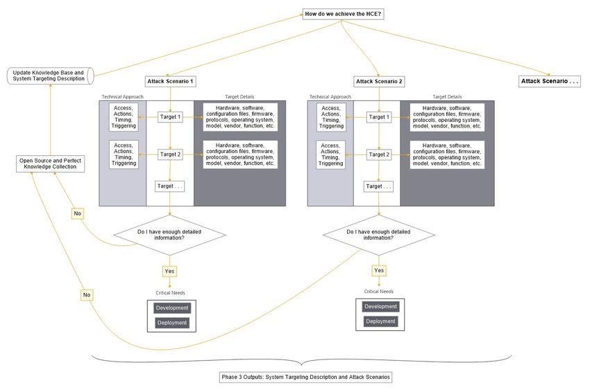
CCE Phase 3: Consequence-based Targeting
Introduction
During Phase 1, Consequence Prioritization, the CCE Team identified High Consequence Events (HCEs)
that could be accomplished through cyber means to impact critical functions, services, and processes.
During Phase 2, System-of-Systems Analysis, the CCE Team conducted a systematic review and analysis
of information related to the equipment, systems, processes, operations, maintenance, testing, and
procurement practices based on the HCEs identified in Phase 1.

A summary of the HCE-relevant information collected in Phase 2 was drafted into a System Description,
which serves as the starting point for the targeting analysis performed during Phase 3, Consequence-
based Targeting. The goal of Phase 3 is to develop plausible Attack Scenarios. The CCE Team examines
the data from Phase 2 with an adversarial perspective to brainstorm different ways to achieve the HCE.
The System Targeting Description is used to summarize and reference all the key details that are
required for the Attack Scenarios.

It should be noted that the findings in Phase 3 are not all-inclusive; they represent a set of possible
approaches, called Technical Approaches in CCE, that can disrupt critical systems or functions. At the
same time, these identified Attack Scenarios may be limited or informed by the Boundary Conditions
defined in Phase 1. The Target Details describe each location where manipulation or compromise occurs
in an Attack Scenario to make the HCE possible. Target Details include all the technical details an
adversary would need.

While Phase 2 was a data collection effort, Phase 3 is a targeting effort. In Phase 3, organizations
systematically identify the necessary steps for adversary success—all from the adversary’s perspective.
A key component to this approach is identifying the critical information needs, targets, access, and
actions required for the adversary to achieve the HCE. These Critical Needs are tied to accomplishing
the HCE, such as the technical requirements for the payload (Development), or the access required to
deliver a payload (Deployment).

Critical Needs can and will be identified outside of an entity’s network boundary or direct control
(vendors, suppliers, subcontractors, regulatory, or financial filings) as well as through publicly available,
open-source resources found in various places. An entity’s ability to identify what these Critical Needs
are, where they reside, and who has access to them is a crucial step in understanding—and ultimately
mitigating—risk.

For the CCE Team, the definition of critical information should extend well beyond documentation
because an adversary will need to understand precisely how a process or piece of equipment functions
to achieve a specific effect. To gain this type of knowledge, the adversary may need to acquire
equipment, software, configuration files, or even access somewhere in the supply chain. An
understanding of Critical Needs can also be used as the basis for “tripwires” that flag adversary activity
related to the HCE.

 1
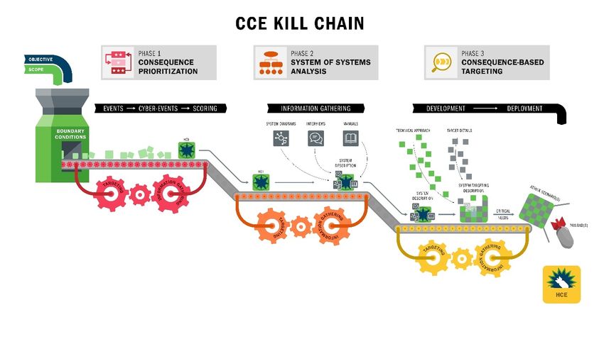
Visualizing Cyber-enabled Sabotage with the CCE Kill Chain
The CCE Kill Chain (see Figure 1 on the next page) was developed to help illustrate the activities an
adversary must accomplish in order to cause cyber-enabled sabotage. Assembling the cumulative
knowledge, capability, and access that is needed to maliciously manipulate a system requires a long
term “campaign” of iterative targeting and information collection activities. The results achieved by
these efforts are required for the associated payload Development and Deployment activities. They also
directly relate to the success of a cyber sabotage campaign. Therefore, if a roadblock is met in payload
Development, or new information or accesses become available, all the activities in the campaign will
adjust to the new requirements.
The main reason for using the CCE Kill Chain is CCE’s focus on understanding (and ultimately disrupting)
the requirements an adversary needs to achieve the HCE. For example, adversaries may target vendors
and subcontractors through supply chain or human recruitment tactics in conjunction with a cyber
campaign. 1 This is done to both obtain critical information and gain necessary access for the deployment
of capabilities. A highly resourced and motivated attacker may insert corrupt components or software
several layers into the supply chain. An attacker might also investigate co-opting insiders or have their
own agents apply for critical positions at the target organization, a subcontractor, or a vendor.
Rather than focusing on the network and cyber hygiene details for every possible cyber access point, the
CCE Kill Chain will identify areas of unverified trust in the implementation, operation, or maintenance of
a targeted control system. These instances of unverified trust are sources for Critical Needs an adversary
requires.

1
 One concerning example of supply chain manipulation was demonstrated during the Havex campaign in 2014.
During this infection campaign, the adversary intercepted and altered update packages for ICS and auxiliary
equipment. This effort directly targeted the operations of its victims by piggybacking on the update process for
non-internet facing and air-gapped machines.

 2
You can also read