PORTLAND, OREGON Design of Small Photovoltaic (PV) Solar-Powered Water Pump Systems - Natural Resources ...
←
→
Page content transcription
If your browser does not render page correctly, please read the page content below
Technical Note No. 28
               PORTLAND, OREGON

Natural
Resources
Conservation
               Design of Small
Service        Photovoltaic (PV)
October 2010
               Solar-Powered Water
               Pump Systems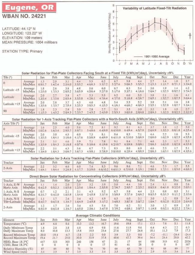
Design of Small Photovoltaic (PV) Solar-Powered Water Pump Systems

Issued October 2010

Cover photo courtesy of Nicholle Kovach, Basin Engineer, USDA NRCS.

Trade names mentioned are for specific information and do not constitute a
guarantee or warranty of the product by the Department of Agriculture or
an endorsement by the Department over other products not mentioned.

The U.S. Department of Agriculture (USDA) prohibits discrimination in all its
programs and activities on the basis of race, color, national origin, age,
disability, and where applicable, sex, marital status, familial status, parental
status, religion, sexual orientation, genetic information, political beliefs, re-
prisal, or because all or a part of an individual’s income is derived from any
public assistance program. (Not all prohibited bases apply to all programs.)
Persons with disabilities who require alternative means for communication
of program information (Braille, large print, audiotape, etc.) should contact
USDA’s TARGET Center at (202) 720–2600 (voice and TDD).

To file a complaint of discrimination, write to USDA, Director, Office of Civil
Rights, 1400 Independence Avenue, SW., Washington, DC 20250–9410, or
call (800) 795–3272 (voice) or (202) 720–6382 (TDD). USDA is an equal
opportunity provider and employer.

         Technical Note No. 28, October 2010                                      ii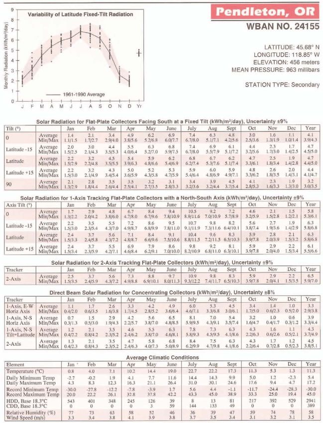
Design of Small Photovoltaic (PV) Solar-Powered Water Pump Systems

 ACKNOWLEDGEMENTS

 This technical note was written by Teresa D. Morales, Oregon State
 Design Engineer, United States Department of Agriculture (USDA)
 Natural Resources Conservation Service (NRCS), Portland, Oregon, and
 John Busch, Oregon State Irrigation Engineer, USDA NRCS, Baker City,
 Oregon.

 Drawings by Kristi Yasumiishi, Civil Engineering Technician, USDA NRCS,
 Portland, Oregon.

 Reviewed by Dave Dishman, Oregon State Engineer, USDA NRCS,
 Portland, Oregon; Stefanie Aschmann, Leader of Energy Technology
 Development Team, NRCS West National Technology Support Center
 (WNTSC), Portland, Oregon; Peter Robinson, Water Management
 Engineer, NRCS WNTSC, Portland, Oregon; Clarence Prestwich,
 Irrigation Engineer, NRCS WNTSC, Portland, Oregon; Kip Yasumiishi,
 Civil Engineer, NRCS WNTSC, Portland, Oregon; Kelly Albers, Basin
 Engineer, USDA NRCS, Tangent, Oregon; Ginny Cairo, Basin Engineer,
 USDA NRCS, Roseburg, Oregon; Bill Cronin, Basin Engineer, USDA NRCS,
 Medford, Oregon; Kevin Shaw, Basin Engineer, USDA NRCS, Baker City,
 Oregon.

 Edited by Erin McDuff, Administrative Assistant, USDA NRCS, Portland,
 Oregon.

     Technical Note No. 28, October 2010                                 iii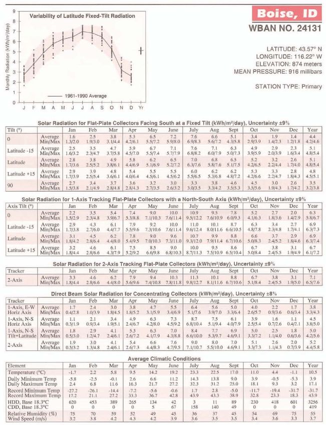
Design of Small Photovoltaic (PV) Solar-Powered Water Pump Systems

 PREFACE

 The intent of this technical publication is to provide general guidance on
 the design of small solar-powered water pump systems for use with
 livestock operations or irrigation systems. This document provides a
 review of the basic elements of electricity, a description of the different
 components of solar-powered water pump systems, important planning
 considerations, and general guidance on designing a solar-powered
 water pump system. This publication also provides design examples for
 typical design scenarios and standard drawings for use by the reader.
 However, this technical note is not intended to be used as a standalone
 document. Instead, users are encouraged to consult the NRCS National
 Engineering Manual (NEH 210) on hydraulics and irrigation engineering
 for additional assistance in the design of water delivery systems.

 All sources used in the development of this technical note are provided
 in the References section at the back of the document.

     Technical Note No. 28, October 2010                                  iv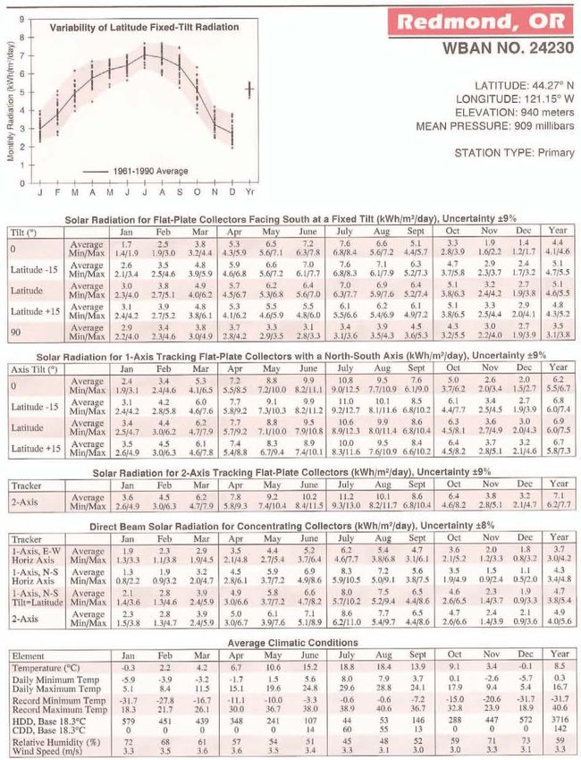
Design of Small Photovoltaic (PV) Solar-Powered Water Pump Systems

CONTENTS

1.     INTRODUCTION ............................................................................................................................................ 1
     1.0    ELECTRICITY BASICS ..............................................................................................................................................2
     1.1    THE PHOTOELECTRIC EFFECT ..................................................................................................................................2
2.     SOLAR RADIATION, SOLAR IRRADIANCE, AND SOLAR INSOLATION .............................................................. 3
     2.0    SEASONAL AND LATITUDE VARIATION .......................................................................................................................5
     2.1    CLOUD COVER .....................................................................................................................................................5
3.     PHOTOVOLTAIC (PV) PANELS ........................................................................................................................ 6
     3.0    PV PANEL ELECTRICAL CHARACTERISTICS ..................................................................................................................6
     3.1    PV PANEL ORIENTATION AND TRACKING ..................................................................................................................7
     3.2    ENVIRONMENTAL FACTORS ....................................................................................................................................8
4.0    STRUCTURE AND FOUNDATION CONSIDERATIONS ....................................................................................... 8
     4.0    STRUCTURAL SUPPORTS FOR PV PANELS...................................................................................................................8
     4.1    MOUNTING POSTS ...............................................................................................................................................8
     4.2    EMBEDMENT CONSIDERATIONS FOR MOUNTING POSTS...............................................................................................9
     4.3    CORROSION PROTECTION.......................................................................................................................................9
5.0    ELECTRICAL CONTROLLERS ......................................................................................................................... 10
6.0    SOLAR-POWERED PUMPS ........................................................................................................................... 11
     6.0    PUMP SELECTION AND SYSTEM DESIGN ..................................................................................................................11
     6.1    SOLAR-POWERED PUMP CHARACTERISTICS .............................................................................................................13
7.     DESIGN PROCESS ........................................................................................................................................ 14
     7.0    STEP 1 – WATER REQUIREMENT ...........................................................................................................................14
     7.1    STEP 2 – WATER SOURCE ....................................................................................................................................14
     7.2    STEP 3 – SYSTEM LAYOUT ....................................................................................................................................15
     7.3    STEP 4 – WATER STORAGE ..................................................................................................................................17
     7.4    STEP 5 – SOLAR INSOLATION AND PV PANEL LOCATION.............................................................................................17
     7.5    STEP 6 – DESIGN FLOW RATE FOR THE PUMP ..........................................................................................................17
     7.6    STEP 7 – TOTAL DYNAMIC HEAD (TDH) FOR THE PUMP ............................................................................................18
     7.7    STEP 8 – PUMP SELECTION AND ASSOCIATED POWER REQUIREMENT ...........................................................................18
     7.8    STEP 9 – PV PANEL SELECTION AND ARRAY LAYOUT .................................................................................................18
     7.9    STEP 10 – PV ARRAY MOUNTING AND FOUNDATION REQUIREMENTS..........................................................................18
     7.10   STEP 11 – WATER FLOW RATES AND DELIVERY POINT PRESSURE ................................................................................19
     7.11   STEP 12 – SUMMARY DESCRIPTION OF THE SYSTEM..................................................................................................19
8.     ADDITIONAL CONSIDERATIONS .................................................................................................................. 19

                                                             Technical Note No. 28, October 2010                                                                            v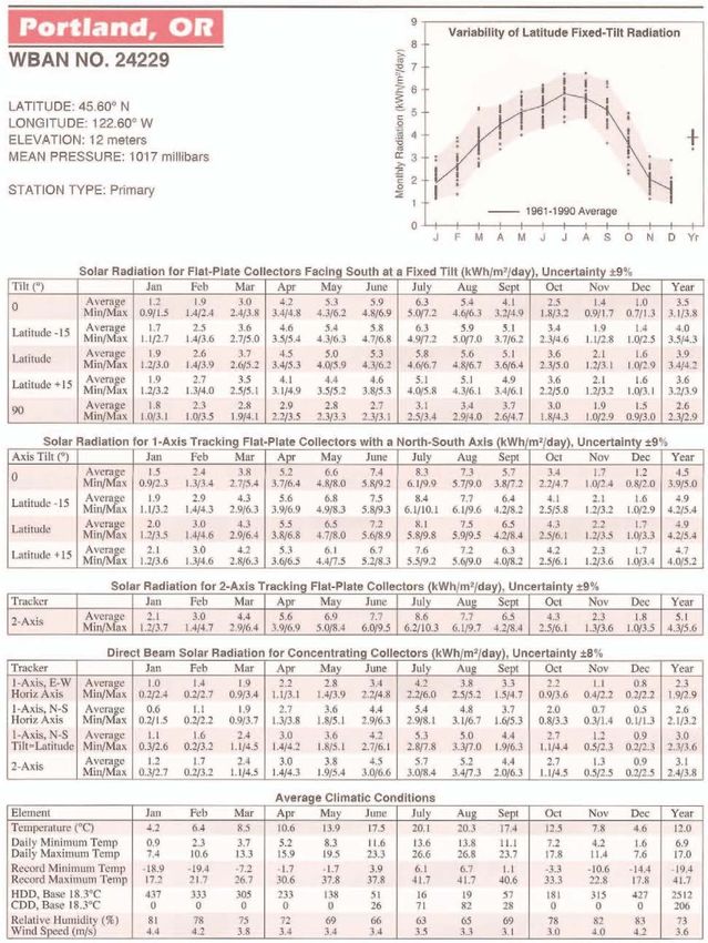
Design of Small Photovoltaic (PV) Solar-Powered Water Pump Systems

APPENDIXES

APPENDIX A:             REFERENCES ............................................................................................................................. 20
APPENDIX B:             ADDITIONAL RESOURCES .......................................................................................................... 21
APPENDIX C:             DESIGN EXAMPLES ................................................................................................................... 22
    DESIGN EXAMPLE 1:              SOLAR-POWERED WATER PUMP SYSTEM USING SURFACE WATER (A STREAM) AS A WATER SOURCE .....22
    DESIGN EXAMPLE 2:              SOLAR-POWERED WATER PUMP SYSTEM USING SUBSURFACE WATER (A WELL) AS A WATER SOURCE ...28
APPENDIX D:             SOLAR INSOLATION VALUES FOR OREGON .............................................................................. 36
APPENDIX E:             NREL APPROACH TO DETERMINING SOLAR INSOLATION VALUES ............................................ 46
APPENDIX F:             STANDARD DRAWINGS............................................................................................................. 50
APPENDIX G:             FRICTION HEAD LOSS FOR SCHEDULE 40 PVC PLASTIC PIPE ...................................................... 56
APPENDIX H:             SAMPLE WELL LOG ................................................................................................................... 57
APPENDIX I:             OREGON DEPARTMENT OF FISH AND WILDLIFE FISH SCREENING CRITERIA .............................. 58
APPENDIX J:             SOLAR PANEL WIRING .............................................................................................................. 60
APPENDIX K:             GLOSSARY OF SOLAR-POWERED WATER PUMP TERMS ............................................................ 61

LIST OF FIGURES

FIGURE 1 – A TYPICAL SOLAR-POWERED WATER PUMP SYSTEM, WHICH INCLUDES A SOLAR ARRAY, CONTROLLER, PUMP, AND STORAGE
      TANK. (SOURCE: “THE MONTANA AGSOLAR PROJECT – EXPANDING THE AGRICULTURAL USES OF SOLAR ENERGY IN MONTANA.”) 1
FIGURE 2 – THE PHOTOELECTRIC EFFECT AND SUBSEQUENT ELECTRON MOTION. (IMAGE INSPIRED BY .................................................3
FIGURE 3 – SOLAR IRRADIANCE AND PEAK SUN HOURS. ..............................................................................................................4
FIGURE 4 – EXAMPLE SUMMER AND WINTER SUN ELEVATION AND ANGLE. (SOURCE: “RENEWABLE ENERGY PRIMER-SOLAR.”) ...............5
FIGURE 5 – SOLAR CELL, PV SOLAR PANEL, AND PV PANEL ARRAY. (SOURCE: “GUIDE TO SOLAR POWERED WATER ...............................6
FIGURE 6 – SOLAR PANEL TILT ANGLES: WINTER TILT WITH MORE ANGLE FROM HORIZONTAL [LEFT] AND SUMMER TILT WITH LESS.............8
FIGURE 7 – PV SOLAR ARRAY WITH STORAGE TANK AND STOCK. .................................................................................................11
FIGURE 8 – TYPICAL SURFACE INSTALLATION WITH PERTINENT PARAMETERS. ................................................................................12
FIGURE 9 – TYPICAL WELL INSTALLATION WITH PERTINENT PARAMETERS......................................................................................12
FIGURE 10 – EXAMPLE SOLAR-POWERED PUMP PERFORMANCE CURVES FOR A POSITIVE DISPLACEMENT PUMP....................................13
FIGURE 11 – EXAMPLE SOLAR-POWERED PUMP PERFORMANCE CURVES FOR A CENTRIFUGAL PUMP. .................................................13
FIGURE 12 – A PLAN OF AN EXAMPLE WATERING SYSTEM WITH A STORAGE TANK AND PV ARRAY. ....................................................16
FIGURE 13 – ELEMENTS OF A TYPICAL INSTALLATION SUPPLIED BY A SURFACE WATER SOURCE. .........................................................16

                                                        Technical Note No. 28, October 2010                                                                     vi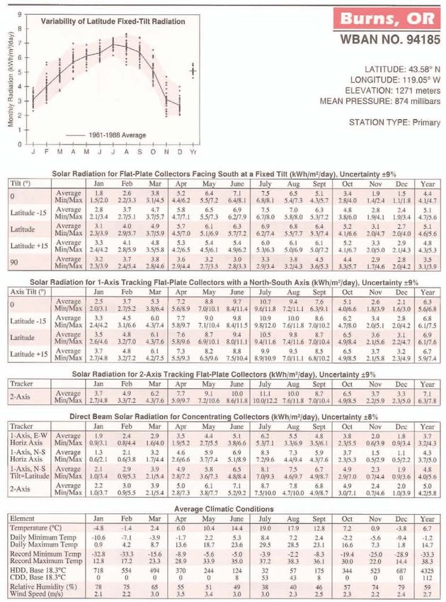
Design of Small Photovoltaic (PV) Solar-Powered Water Pump Systems

LIST OF TABLES

TABLE 1 – ELECTRICITY FOR NON-ELECTRICAL .........................................................................................................................2
TABLE 2 – SOLAR RADIATION FOR FLAT-PLATE COLLECTORS FACING SOUTH AT A FIXED TILT OF 43° FOR NORTH BEND, OR ................4
TABLE 3 – EXAMPLE PV SOLAR PANEL ELECTRICAL ..................................................................................................................6
TABLE 4 – TYPICAL WATER USE REQUIREMENTS ...................................................................................................................14

LIST OF EQUATIONS

EQUATION 1......................................................................................................................................................................2
EQUATION 2......................................................................................................................................................................2
EQUATION 3....................................................................................................................................................................18

                                                             Technical Note No. 28, October 2010                                                                             vii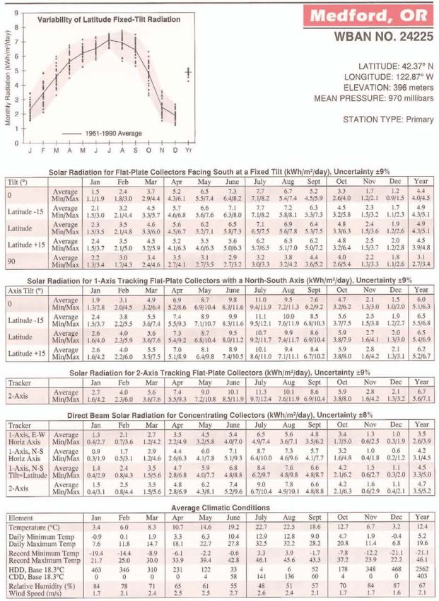
Design of Small Photovoltaic (PV) Solar-Powered Water Pump Systems

1. INTRODUCTION

Photovoltaic (PV) panels are often used for
agricultural operations, especially in remote
areas or where the use of an alternative energy
source is desired. In particular, they have been
demonstrated time and time again to reliably
produce sufficient electricity directly from solar
radiation (sunlight) to power livestock and
irrigation watering systems.

A benefit of using solar energy to power
agricultural water pump systems is that
increased water requirements for livestock and
irrigation tend to coincide with the seasonal
increase of incoming solar energy. When
properly designed, these PV systems can also
result in significant long-term cost savings and a      Figure 1 – A typical solar-powered water pump system,
smaller environmental footprint compared to                       which includes a solar array, controller, pump,
conventional power systems.                                       and storage tank. (Source: “The Montana
                                                                  Agsolar Project – Expanding the Agricultural
The volume of water pumped by a solar-                            Uses of Solar Energy in Montana.”)
powered system in a given interval depends on
the total amount of solar energy available in             •   The site-specific solar energy available
that time period. Specifically, the flow rate of              (referred to as “solar insolation”).
the water pumped is determined by both the                •   The volume of water required in a given
intensity of the solar energy available and the               period of time for livestock or irrigation
size of the PV array used to convert that solar               purposes, as well as for storage. (A
energy into direct current (DC) electricity.                  storage volume equal to a three-day
                                                              water requirement is normally
The principle components in a solar-powered                   recommended for livestock operations as
water pump system (shown in Figure 1, right)                  a backup for the system’s safety features
include:                                                      and cloudy days.)
                                                          •   The total dynamic head (TDH) for the
  •   The PV array and its support structure,
                                                              pump.
  •   An electrical controller, and
                                                          •   The quantity and quality of available
  •   An electric-powered pump.
                                                              water.
                                                          •   The system’s proposed layout and
It is important that the components be
                                                              hydraulic criteria.
designed as part of an integrated system to
ensure that all the equipment is compatible and
                                                        The following sections will first provide an
that the system operates as intended. It is
                                                        introduction to the basic concepts involved in
therefore recommended that all components
                                                        solar-powered pump systems, then descriptions
be obtained from a single supplier to ensure
                                                        of and design considerations for the previously
their compatibility.
                                                        mentioned, individual system components.
                                                        (See Appendix K: Glossary of Solar-Powered
The following information is required to design
                                                        Water Pump Terms for definitions of the
a PV-powered pump:
                                                        technical terms and abbreviations used.)

                              Technical Note No. 28, October 2010                                    Page 1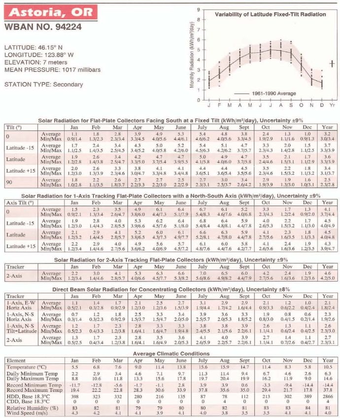
Design of Small Photovoltaic (PV) Solar-Powered Water Pump Systems

1.0 Electricity Basics                                   Table 1 – Electricity for Non-Electrical
                                                                    Engineers
It is important to be familiar with fundamental          Electricity in a Wire      Water in a Pipe
electrical concepts, such as energy, voltage,            Amp                        Q
amperage, and resistance, before you begin to             (flow of electrons)        (flow rate of water)
design a solar-powered water pump system.                Volts                      Pressure
                                                          (energy potential)         (energy potential)
Voltage is the electrical potential (i.e. the            Watts (power)              Hydraulic/Water Power
pressure) in the solar-powered system. It is             = Amps x Volts             = Q x Pressure
measured in units of Volts (V).                          Resistance                 Friction + Minor Losses
                                                         High Voltage, Small        High Pressure, Small
Amperage refers to the movement or flow of               Wire = High Amps, High Pipe = High Velocity,
electrons (i.e. the electrical current) through          Resistive losses, Heat     High Friction Losses,
the system. It is measured in units of Amps (A).         and Fires                  Blown Pipe

Voltage multiplied by amperage is the power              loss is also influenced by the wire material: a
produced. It is measured in units of watts (Pw),         good conductor, such as copper, has a low
as shown in Equation 1:                                  resistance and will result in less energy loss.

                                                         Another effective way to reduce electrical
   Watts = Volts x Amps
                                                         losses in a system is to decrease the current
                                     Equation 1          flow. Power losses in an electrical circuit are
                                                         proportional to the square of the current, as
Electrical energy is the amount of power                 shown in Equation 2:
generated over a period of time. Energy is
typically measured in kilowatt-hours (kWh).
                                                            Power Loss = Current2 x Resistance
Lastly, resistance is a measure of a material’s                                            Equation 2
resistance to the flow of electrons across it. It is
measured in Ohms (Ω).                                    Consequently, as indicated in Equations 1 and 2,
                                                         increasing the voltage while reducing the
A good analogy to help describe the flow of              current will result in the same power
electrons in a wire is the flow of water through         transmission, but with less power loss.
a pressurized line. In order to illustrate this          Therefore, higher voltage pumps tend to be
analogy, Table 1 (right) compares the flow of            more efficient than lower voltage pumps,
electricity through a circuit with the flow of           assuming all other properties are similar.
water through a pipe.
                                                         1.1 The Photoelectric Effect
As with water flowing through a pipe, resistance
(friction, in the case of water) in the electrical       PV systems harness the sun’s energy by
line results in an energy loss in the system. It is      converting it into electricity via the
influenced by the length, size, and type of wire         photoelectric effect. This occurs when
conductor. Specifically, resistance is                   incoming photons interact with a conductive
proportional to the length of the wire and               surface, such as a silicon cell or metal film, and
inversely proportional to the cross-sectional            electrons in the material become excited and
area of the wire. In other words, the longer the         jump from one conductive layer to the other, as
wire, the greater the loss and the larger the            shown in Figure 2, on the following page.
wire diameter, the less the loss. The energy

                               Technical Note No. 28, October 2010                                  Page 2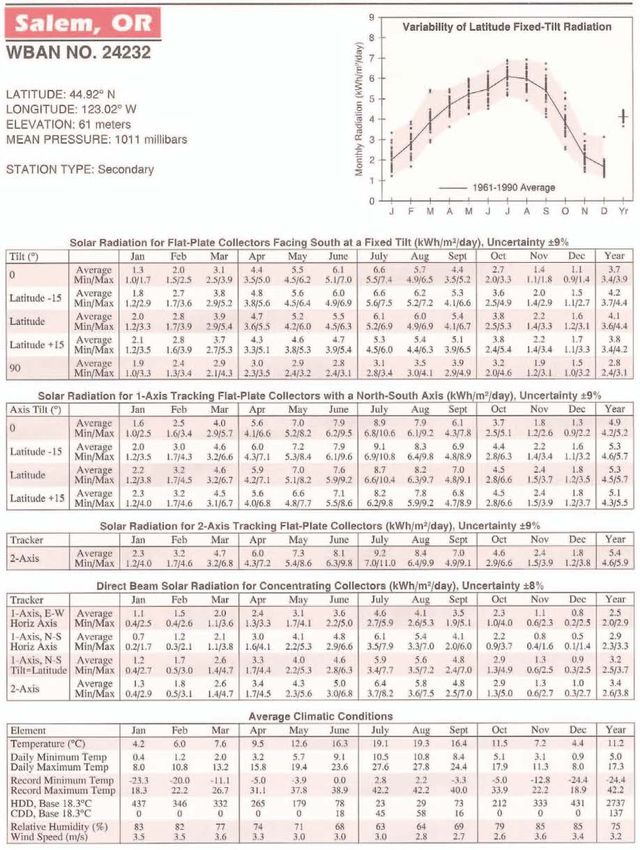
Design of Small Photovoltaic (PV) Solar-Powered Water Pump Systems

        Figure 2 – The photoelectric effect and subsequent electron motion. (Image inspired by
                   Merriam-Webster, 2006.)

In this figure, the excitation of electrons and             radiation,” “solar irradiance,” and “solar
their movement from the p-layer to the n-layer              insolation.”
results in a voltage differential across the
electrical circuit, causing electrons to flow               Solar radiation is the energy from the sun that
through the rest of the circuit to maintain a               reaches the earth. It is commonly expressed in
charge balance. The system is designed so that              units of kilowatts per square meter (kW/m2).
there is an electrical load in the external circuit,        The earth receives a nearly constant 1.36
permitting the current flow to perform a useful             kW/m2 of solar radiation at its outer
function. In other words, the behavior of                   atmosphere. However, by the time this energy
electrons in the solar cell creates a voltage that          reaches the earth’s surface, the total amount of
can be utilized to, for example, operate a water            solar radiation is reduced to approximately 1
pump system.                                                kW/m2.

2. SOLAR RADIATION, SOLAR                                   The intensity of sunshine (i.e. solar radiation)
                                                            varies based on geographic location. A good
   IRRADIANCE, AND SOLAR INSOLATION
                                                            analogy to describe this variation is the
To design a solar-powered water pump system,                different conditions that can be found on the
you will need to quantify the available solar               north slope of a mountain versus its south
energy. It is therefore important for you to be             slope.
familiar with the definitions and distinctions
                                                            The intensity of sunlight also varies based on
between the three related terms “solar
                                                            the time of day because the sun’s energy must

                               Technical Note No. 28, October 2010                                       Page 3
Design of Small Photovoltaic (PV) Solar-Powered Water Pump Systems
pass through different amounts of the earth's
atmosphere as the incident angle of the sun
changes. Solar intensity is greatest when the
sun is straight overhead (also known as solar
noon) and light is passing through the least
amount of atmosphere. Conversely, solar
intensity is least during the early morning and
late afternoon hours when the sunlight passes
through the greatest amount of atmosphere. In
most areas, the most productive hours of
sunlight (when solar radiation levels approach 1
kW/m2) are from 9:00 a.m. to 3:00 p.m.
Outside of this time range, solar power might
still be produced, but at much lower levels. Figure 3 – Solar irradiance and peak sun hours.
(Source: “Renewable Energy Primer-Solar.”)
Solar irradiance, on the other hand, is the
amount of solar energy received by or projected
onto a specific surface. Solar irradiance is also hours.” Occasionally, the term “solar radiation”
expressed in units of kW/m2 and is measured at can also be used to describe equivalent full sun
the surface of the material. In the case of a PV- hours (in addition to the definition above), as in
powered system, this surface is the solar panel. Appendix D.
Finally, solar insolation is the amount of solar Two important considerations when
irradiance measured over a given period of determining solar insolation values are the
time. It is typically quantified in peak sun hours, latitude of the project site and the proposed tilt
which are the equivalent number of hours per angle of the PV array. (The tilt angle, which is
discussed in Section 3.1, is the angle of the
day when solar irradiance averages 1 kW/m2. It
is important to note that although the sun may panel relative to horizontal where 0° is
be above the horizon for 14 hours in a given horizontal and 90° is vertical. Latitude is
day, it may only generate energy equivalent to discussed in Section 2.0). An example of
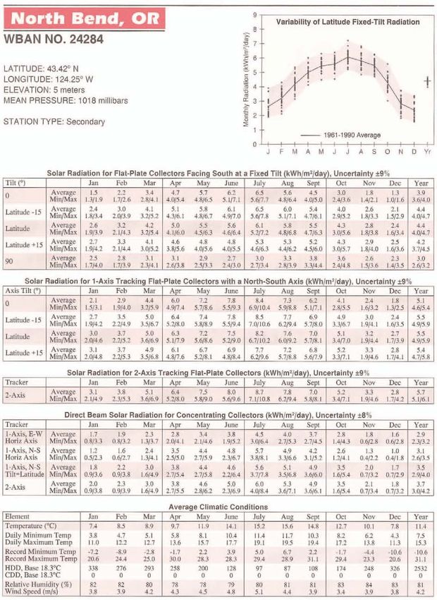
6 peak sun hours. monthly solar insolation values for North Bend,
Oregon (latitude 43 degrees) for a fixed tilt
Figure 3, right, demonstrates how peak sun angle is shown in Table 2, below. Additional
hours are determined for any particular day. solar insolation (solar radiation) values are
The entire amount of solar irradiance (indicated provided in Appendix D for nine locations in
by the blue arc) is divided by 1 kW/m2, which Oregon. (Data for Boise, Idaho, are also
equals the total number of peak sun hours for included in Appendix D due to its proximity to
that day (indicated by the white rectangle). eastern Oregon.)
Another term that is synonymous with peak sun An approach for determining solar insolation
hours (solar insolation) is “equivalent full sun values for locations not listed in these solar
Table 2 – Solar Radiation for Flat-Plate Collectors Facing South at a Fixed Tilt of 43° for North Bend, OR
(kWh/m2/day), Uncertainty +/-9%
North Bend, OR Jan Feb Mar Apr May Jun Jul Aug Sep Oct Nov Dec Year
Latitude - 15° =
43 – 15 = 28° 2.4 3.0 4.1 5.1 6.8 6.1 6.5 6.5 6.0 5.4 4.0 2.6 4.4
Technical Note No. 28, October 2010 Page 4Design of Small Photovoltaic (PV) Solar-Powered Water Pump Systems
tables has been developed by researchers at Adjusting the tilt angle of the PV array to
the U.S. Department of Energy’s National account for seasonal variations in the sun’s
Renewable Energy Lab (DOE-NREL). NREL has elevation can result in increased electrical
developed two software packages (PVWATTS v. power output from the array. Additional
1 and PVWATTS v. 2) that can determine solar information on adjusting for tilt angle is
insolation values, as well as cost estimates for provided in Section 3.1.
different types of solar-powered systems. A
simple introduction to how to use PVWATTS v.2 2.1 Cloud Cover
(Beta) FlexViewer is provided in Appendix E.
Clouds, fog, and overcast skies are common
2.0 Seasonal and Latitude Variation weather events that occur throughout the year
across Oregon, but particularly in the western
In addition to the variation of sunlight intensity part of the state during the winter months.
on any given day, the seasonal variation of Their effects are reflected in the solar insolation
intensity must also be considered when data shown in Appendix D. The tables include
planning for a solar-powered system. In the maximum, minimum, and average values with a
northern hemisphere, the least amount of ±9 percent uncertainty. Reduction or
sunlight occurs in the winter because the days adjustment of the solar insolation values
are shorter and the sun is lower in the sky, as (equivalent full sun hours) is not needed as the
shown in Figure 4, below. In Oregon effects of cloud cover are already accounted
specifically, there is also typically increased for. Instead, it is recommended that the
cloud cover in many regions during the winter designer use the average values included in
months (which is discussed further in the these tables unless local conditions (such as for
following section). Therefore, sunlight intensity sites located under heavy vegetation or in
is least during December and greatest during unusual geological features) warrant otherwise.
mid-summer in the June – July period.
Figure 4 – Example summer and winter sun elevation and angle. (Source: “Renewable Energy Primer-Solar.”)
Technical Note No. 28, October 2010 Page 5Design of Small Photovoltaic (PV) Solar-Powered Water Pump Systems
3. PHOTOVOLTAIC (PV) PANELS 3.0 PV Panel Electrical Characteristics
PV panels are made up of a series of solar cells, PV panels are rated according to their output,
as shown in Figure 5, below. Each solar cell has which is based on an incoming solar irradiance
two or more specially prepared layers of of 1 kW/m2 at a specified temperature. Panel
semiconductor material that produce DC output data include peak power (Watts [Pw]),
electricity when exposed to sunlight. A single, voltage (Volts [V]), and current (Amps [A]).
typical solar cell can generate approximately 3 Under conditions of reduced solar radiation, the
watts of energy in full sunlight. current produced is decreased accordingly, but
the voltage is reduced only slightly. Example
electrical characteristics for a solar panel are
The semiconductor layers can be either shown in Table 3.
crystalline or thin film. Crystalline solar cells are
generally constructed out of silicon and have an
Table 3 – Example PV Solar Panel Electrical
efficiency of approximately 15%. Solar cells that
Characteristics
are constructed out of thin films, which can
consist of a variety of different metals, have Characteristic Value Units
efficiencies of approximately 8% to 11%. They Peak Power 117 Watt [Pw]
are not as durable as silicon solar cells, but they Power Tolerance ±5 %
are lighter and considerably less expensive. Max Power Voltage 35.5 Volts [V]
Max Power Current 3.3 Amps [A]
PV panels may be arranged in arrays and Open Circuit Voltage 40.0 Volts [V]
connected by electrical wiring to deliver power Short Circuit Current 3.5 Amps [A]
to a pump (see Section 3.0 for more details).
PV panels must meet all NRCS required Multiple panel arrays should be wired in a
specifications, both for power production and series and/or parallel so that the resulting
structural integrity (including resistance to hail), voltage and current are compatible with the
as described in the following sections. controller and pump motor requirements.
PV Solar Cell PV Solar Panel Array of PV Solar Panels
Figure 5 – Solar cell, PV solar panel, and PV panel array. (Source: “Guide to Solar Powered Water
Pumping Systems in New York State.”)
Technical Note No. 28, October 2010 Page 6Design of Small Photovoltaic (PV) Solar-Powered Water Pump Systems
When multiple panels are wired in a series, the trackers tend to be more appropriate for sites
total output voltage is the sum of the individual between +/- 30 degrees latitude. Also, their
panel output voltages; the total current stays benefits at higher altitudes tend to be less
the same. Conversely, when panels are wired in during the winter months when the sun is low
parallel, the voltage stays the same while the on the horizon.
resultant total current is the sum of the
individual panel current inputs. The total power In general, though, due to the complexity of
output from a PV panel array is determined by tracking mechanisms and their associated
multiplying the total output voltage by the total controls, most installations for water pumps are
output current. (Basic PV panel wiring diagrams stationary and oriented due south to take
are shown in Appendix J.) advantage of the maximum sunlight available in
the middle of the day.
The power output from a PV panel can vary
slightly from the panel’s rated power, as noted The default tilt angle for a PV panel is equal to
by the “Power Tolerance” value in Table 3. the latitude of the location. For a fixed array,
Power output will also decline at about one this default angle will maximize annual energy
percent per year due to environmental wear on production.
the system. Oregon Construction Specification
68: Photovoltaic (PV) Power Supply for Pump A tilt angle of +/- 15 degrees from latitude will
specifies that the panel output shall be increase energy production for the winter or
warranted against a degradation of power summer months, respectively. Most solar
output in excess of 10 percent in a 10-year panels that are used for water pumping are set
period following installation. to collect the maximum amount of energy in
the summer, when water demands are
3.1 PV Panel Orientation and Tracking greatest. However, to maximize energy for
both summer and winter pumping, it is
To be most effective, PV panels need to recommended that the tilt angle be adjusted at
continuously and directly face incoming the spring and autumn equinoxes (March 21st
sunlight, which requires the use of one or two and September 21st). In other words, the panel
tracking mechanisms. A single-axis tracking array tilt angle should be adjusted as follows:
mechanism will rotate a PV panel about its
vertical axis to follow the sun throughout the • Summer tilt angle = latitude – 15°
day. A double-axis mechanism will also control (when the sun is higher in the sky).
the panel tilt angle (the angle of the panel • Winter tilt angle = latitude + 15°
relative to horizontal where 0° is horizontal and (when the sun is lower in the sky).
90° is vertical) to adjust for the elevation of the
sun in the sky throughout the year. For example, latitudes in Oregon range from 42°
to 46° north, so summer tilt angles are expected
Single-axis tracking can be very effective for to range from 27° to 31° while winter tilt angles
increasing energy production throughout the should range from 57° to 61°. (The PV arrays in
year, by up to 50% during some months. Figure 6, on the following page, show the
Passive single trackers, which require no energy different tilt angles for both summer and
input, can be used. They use the heat from the winter.)
sun to cause freon or a substitute refrigerant to
move between cylinders in the tracker Note that if the array’s tilt angle is adjusted
assembly, which causes the panels to shift so seasonally, the site’s solar insolation data that is
that they maintain a constant 90-degree angle used in the design of the solar-powered water
to the sun throughout the day. Single-axis pump system should reflect this.
Technical Note No. 28, October 2010 Page 7Design of Small Photovoltaic (PV) Solar-Powered Water Pump Systems
Figure 6 – Solar panel tilt angles: winter tilt with more angle from horizontal [left] and summer tilt with less
angle from horizontal [right]. (Source: “Renewable Energy Primer-Solar.”)
3.2 Environmental Factors meet all expected load cases as defined in the
Oregon Construction Specification 68.
PV panels and all associated components (the
mounting structure, power controller, and 4.1 Mounting Posts
electrical connections) are subject to a host of
environmental stresses, such as high A solar panel array mounted to a post behaves
temperatures; dust; significant wind, snow, ice, essentially in the same way as a sign or
or hail loading; etc. To withstand such stresses, billboard and is therefore subject to the same
NRCS requires all components associated with types of ice and wind loading. A properly
powering a water pump to meet or exceed all mounted solar panel array will result in a
current industry standards as specified in downward (axial) and lateral point load at the
Oregon Construction Specification 68. top of the mounting post while minimizing any
eccentric loading. Correctly analyzing these
4.0 STRUCTURE AND FOUNDATION loads is essential for determining the correct
CONSIDERATIONS foundation design and mounting post size.
4.0 Structural Supports for PV Panels NRCS has developed three sets of standard
drawings for solar-powered water pump
The structural supports used to attach the PV systems. Copies of these drawings are located
panels to their mounting posts are typically in Appendix F. The first sheet of each set of
provided by the solar panel manufacturer. The drawings provides a mounting post selection
supports must be installed per the table. This table provides minimum pipe sizes,
manufacturer’s specifications to avoid any embedment depths, and concrete volumes
unintended stresses or eccentric loading to the based on the post height and panel array size
panels, structural supports, and/or mounting for a proposed system. The values listed in
posts. These unintended stresses and/or these tables are based on a wind speed of 95
eccentricities can overstress the connection of mph, a 1-inch ice load, and a panel self-weight
the panel to the post, even under normal of 40 lb per panel. Soil properties for the
loading, and damage the system. foundation design were presumed to have an
allowable bearing pressure of 1,500 psf and a
Any structural support used to mount the PV lateral pressure per unit depth of 100 psf/ft .
panels to the post that has not been provided The use of this table for site conditions that
by a certified solar panel manufacturer needs to exceed these design parameters is NOT
Technical Note No. 28, October 2010 Page 8Design of Small Photovoltaic (PV) Solar-Powered Water Pump Systems
acceptable. For a site whose conditions do order to ensure adequate foundation strength,
exceed these design parameters, the required the concrete should be properly batched above
mounting post size and embedment depth will ground prior to placement in the post hole. It is
need to be determined by a qualified engineer. NOT acceptable to place dry ready mix concrete
in the post hole and then backfill the hole with
Care should be taken before mounting a solar water. This method provides no way to ensure
panel array to an existing structure, such as a that the concrete has been adequately mixed
barn or shed. The self-weight of the panels can and the required concrete strength achieved.
be significant, particularly with larger arrays. Instead, the foundation is more likely to fail
Furthermore, the addition of a solar panel array over time, resulting in a tilting panel and a
to a roof can change wind loading patterns on potential reduction in power generation.
that roof. An older structure or a structure not
designed to carry these larger loads could 4.3 Corrosion Protection
potentially be overwhelmed by the addition of a
solar panel array and fail. Corrosion is a potentially serious issue that can
be easily avoided by taking a few simple,
Any questions regarding the suitability of an protective steps.
existing structure for use in mounting a solar
panel array should be directed to a qualified For corrosion to occur, the following four
engineer. elements need to be present:
4.2 Embedment Considerations for Mounting 1) Anode – a corroding metal surface
Posts 2) Cathode – a non-corroding metal surface
3) Electrolyte (solution) – a pathway for
An inadequate embedment depth for the ionic energy transfer
mounting post can cause the panels to tilt or tip 4) Metal Conductor – a pathway for energy
over during normal wind and/or ice loading and transfer
can lead to significant damage to the PV
system. Tilting of the panels will also occur When dissimilar metals (the anode and the
when loading on the panels results in localized cathode) come into contact under wet
failure of the soil column immediately around conditions (the electrolyte), a galvanic potential
the post, which will then be able to move freely is created between the anode and the cathode,
in the ground. Additional loading may lead to leading to the subsequent corrosion of the
progressive failure of the foundation and/or anode. For example, the use of plain carbon
reduced energy production as the panels will no steel bolts, nuts, and washers to attach an
longer be positioned to receive maximum solar aluminum mounting structure to the mounting
insolation. post will begin to corrode the aluminum when
the contact area between the bolts, nuts, and
To reduce the potential for the panels to tip or washers and the aluminum mounting structure
tilt, the foundation must be designed to carry is wet. The aluminum will act as the sacrificial
the expected wind and ice loads, as determined material (anode) since it has a lower galvanic
using the American Society of Civil Engineers potential than the plain carbon steel.
(ASCE) 07 Minimum Design Loads for Buildings
and Other Structures. However, if one of these issues is eliminated,
the corrosion will cease. For example, the
The standard solar-powered water pump moisture may be removed or the contact
system drawings provided in Appendix F call for between the mounting panel and bolts, nuts,
all post holes to be backfilled with concrete. In and washers may be lost. The latter will most
Technical Note No. 28, October 2010 Page 9Design of Small Photovoltaic (PV) Solar-Powered Water Pump Systems
likely occur when the corrosion becomes severe The pump’s operation can also be controlled by
enough to cause the bolted connection to fail. the use of a float switch in the storage tank,
This can result in significant and costly damage which responds automatically when a preset
to the panel array. In terms of the former water level is reached in the tank. Alternatively,
solution, since PV-powered systems are the pump’s operation can be controlled by a
continually exposed to the elements, the pressure switch, which responds when a
presence of moisture around the mounting designated water pressure is attained in the
structure connection is simply unavoidable. system.
Selecting hardware that is made of a similar
material (i.e. that has a similar galvanic A PV system may incorporate storage batteries
potential) is therefore the best and cheapest that can be charged when incoming solar
defense against corrosion. Overlooking this energy exceeds the pumping power
seemingly minor and inexpensive detail can requirement. The batteries can then be used to
result in costly damage to the array. power the pump when the pumping
requirement exceeds the solar power input.
Any questions regarding the appropriate type of The battery charge and discharge will be
fasteners to use should be directed to the regulated by the control unit. The use of
manufacturer, installer, and/or a qualified batteries, however, does require a more
engineer. complex control system and can significantly
increase the cost and maintenance of the PV-
5.0 ELECTRICAL CONTROLLERS powered system. Remember, the first goal of a
solar-powered water pump system is to store
Electrical controllers and safety devices are water, not electricity. The use of batteries
incorporated into PV-powered water pump should therefore be discouraged unless
systems to control the electric power input to absolutely necessary since the added expense
the pump and to provide necessary electrical and complexity usually outweighs any
protection and switching. advantages.
The controller normally includes a main switch A more effective and less expensive means of
to provide an electrical disconnect of the PV utilizing excess incoming solar energy would be
array from all other system components. Since to incorporate a water storage tank into the
the amount of power produced by the array system (see Figure 7, on the following page). A
depends on the intensity of incoming solar storage tank can help meet the operation’s
radiation, the controller can cause the pump to water needs when the demand exceeds the
be switched off until sufficient power is pump output or during non-peak solar
available to meet the pump’s specified insolation hours when only minimal solar
minimum operating power input range. energy is generated.
Likewise, when the PV panels produce too
much power, the controller can limit the power For the safety of the equipment and everyone
output to the pump to prevent it from running who may come into contact with the pump
faster than its maximum rated speed. The system, it is important to properly ground all
performance of the electrical controller will electrical components and solar panel
vary depending on the type of controller structures to reduce the possibility of damage
selected. However, an important safety device from lightning strikes.
that should be included in most systems is a
switch for low water dry run protection.
Technical Note No. 28, October 2010 Page 10Design of Small Photovoltaic (PV) Solar-Powered Water Pump Systems
given pump can be found in the pump
manufacturer’s specifications.
Another important consideration when
selecting the appropriate pump is the pump’s
minimum voltage. Pump manufacturers may
provide pumps with similar operating
characteristics but different voltages. As noted
in Section 1.2, a higher operating voltage tends
to be more efficient since there is less energy
loss from the reduced current required to
deliver the same power (wattage). This is
important when considering the placement of
the panels and controller relative to the
Figure 7 – PV solar array with storage tank and stock. location of the pump. A general rule of thumb
(Source: “Renewable Energy Primer-Solar.”) is that if the array consists of four or more
panels and is located more than 50 feet away
from the pump, the use of a higher voltage
6.0 SOLAR-POWERED PUMPS pump should be considered.
Pumps that use PV systems are normally 6.0 Pump Selection and System Design
powered by DC motors. These motors use the
DC output from the PV panels directly. Factors affecting the selection of a solar-
Alternating current (AC) motors are sometimes powered pump include the following:
used, but they require more complex control
systems. They also result in less total energy • TDH (in feet).
availability due to the electrical losses caused • The water source (surface vs. well).
when an inverter is used to convert the DC to • The available electrical power (peak
AC electricity. Because DC motors do not power) and energy (total energy, i.e.
require an inverter, utilize a less complex power x time) produced by the PV
control system, and result in more total energy panel array.
availability, they are most commonly paired • The water requirement (flow rate
with solar-powered pumps. and/or total volume in a given time
period, including the storage
The type of pump configuration and mounting requirement).
can be either submersible, surface mount, or
floating, depending on the water source. The water quality (including the amount of
sediment, organic content, sand, and total
Solar-powered pumps are characterized as dissolved solids [TDS]) may also be a required
either positive displacement pumps (e.g., consideration for selecting a pump, as per the
diaphragm, piston, or helical rotor) or manufacturer’s specifications.
centrifugal pumps. Positive displacement
pumps are typically used when the TDH is high The pertinent parameters needed for the pump
and the flow rate (measured in gpm) required is system design for typical surface and well
low. Conversely, centrifugal pumps are installations are shown in Figures 8 and 9,
typically used for low TDH and high flow rates. respectively, on the following page.
The TDH and flow rate characteristics for a
Technical Note No. 28, October 2010 Page 11Design of Small Photovoltaic (PV) Solar-Powered Water Pump Systems
Figure 8 – Typical surface installation with pertinent parameters.
Figure 9 – Typical well installation with pertinent parameters.
Technical Note No. 28, October 2010 Page 12Design of Small Photovoltaic (PV) Solar-Powered Water Pump Systems
6.1 Solar-Powered Pump Characteristics to use pump curves is provided in the design
examples located in Appendix C.
A water pump can be selected using pump
performance curves that show the operating Alternatively, some suppliers have computer
characteristics for the solar-powered pump, programs and web-based utilities for selecting
such as those in Figures 10 and 11, below. The and sizing pumps for specified values of
curves in Figure 10 are for positive available solar radiation, pump flow rate, and
displacement pumps, and those in Figure 11 are pumping head.
for centrifugal pumps. An explanation of how
Figure 10 – Example solar-powered pump performance curves for a positive displacement pump.
Figure 11 – Example solar-powered pump performance curves for a centrifugal pump.
Technical Note No. 28, October 2010 Page 13Design of Small Photovoltaic (PV) Solar-Powered Water Pump Systems
7. DESIGN PROCESS Local conditions should be taken into
consideration. Also note that the operation’s
The following twelve steps can be used in the water requirement will vary throughout the
design process for a PV-powered water pump year. (Examples of how to calculate the water
system. These steps will help you ensure that requirement for a solar-powered water pump
the system functions properly and that water is system are given in Design Examples 1 and 2 in
supplied for the operation in the amounts and Appendix C.)
at the locations required.
7.1 Step 2 – Water Source
7.0 Step 1 – Water Requirement
The configuration of the water system will be
The first step in designing a solar-powered defined primarily by the type of water source
water pump system is to determine the overall used, as well as by the local topography and the
water requirement for the operation. This can location(s) of the delivery point(s). The water
be done in part by using the average water source may be either subsurface (a well) or
requirement values for various crops and surface (a pond, stream, or spring).
livestock that are listed in Table 4, below.
If the water source is a well, the following items
will need to be determined:
Table 4 – Typical Water Use Requirements
Approximate Water • The static water level,
Usage (gal/day) 1 • The pumping rate and associated
Animal or Crop
Western Eastern drawdown (along with any seasonal
Oregon Oregon variation), and
Milking Cow 20-25 20-25 • The water quality.
Dry Cow 10-15 15-20
Calf 6-10 10-15 Information on water levels and well
Cow-Calf Pair 15-20 20-25 production can be obtained from the well
Beef Cattle 8-12 20-25 log. (A sample well log is provided in
Sheep or Goat 3-5 5-8 Appendix H and is used in Design Example 2
Horse 12 20-25 in Appendix C.)
Swine, Finishing 3-5 3-5
Swine, Nursery 1 1 The drawdown value obtained from the well
Swine, Sow and Litter 8 8 log should be used to determine the
Swine, Gestating Sow 6 6 production potential of the well to ensure
Elk 4 7 that the well will be able to supply the
Deer 2-3 3 operation’s estimated water needs. If the
100 Chickens 9 9 well log indicates an excessive drawdown
100 Turkeys 15 15 during the given testing time, the well may
Irrigated Crops Use local crop not have the capacity to meet the water
consumptive use demands of the project. If the capacity of the
data. well is in question, a complete well test
Young Trees (in dry 15 15 should be performed and the drawdown
weather) levels measured for different flow rates.
In addition, the drawdown level should be
1
General values adapted from “Midwest Plan used when determining the pumping lift and
Service Structures and Environment Handbook,”
TDH during pumping.
adjusted upward for drier eastern Oregon climate.
Technical Note No. 28, October 2010 Page 14Design of Small Photovoltaic (PV) Solar-Powered Water Pump Systems
If a new well is to be drilled for the project, Additionally, when a surface water source is
information from well logs of existing, nearby used, proper screening of the pump intake is
wells can provide valuable information about necessary to ensure that debris and sediment
the subsurface hydrology in the area and the from the surface water body are not pumped
potential yield of the proposed well. Records of into the system. If the water source contains
well logs are available online from the Oregon anadromous salmonid species of fish, proper
Water Resources Department (WRD). screening of the pump intake is required to
meet Oregon Department of Fish and Wildlife
The expected pumping levels should be (ODFW) fish screen criteria. (A copy of the
determined in areas where water table general criteria is located in Appendix I.
fluctuations occur throughout the year. In Contact the ODFW representative for your area
such areas, a well may even run dry at certain for local screening requirements.)
times of the year. An alternate water source
should be located if there is a potential for an 7.2 Step 3 – System Layout
existing well to run dry during critical
watering times. The third step in the system development
process is to determine the layout of the entire
For most wells, water quality is not an issue if system, including the locations and elevations
the water is not used for human consumption. of the following components:
However, it is a good practice to obtain a water
quality test if there is a potential for fecal • Water source
coliform contamination, high nitrates or salinity, • Pump
organic contaminants, and/or the presence of • PV panels
heavy metals, which may be the case for wells • Storage tanks
located in unique geological features, such as • Points of use (i.e. water troughs)
volcanic terrain. • Pipeline routes
Questions or comments regarding well drilling An example of a proposed system layout is
and/or water quality testing should be directed provided in Figures 12 and 13, below.
to the NRCS State Geologist.
It is also important to consider potential
For surface water sources, such as a stream, vandalism and theft when locating PV panels
pond, or spring, the following need to be and pump systems. Unfortunately, since most
determined, taking seasonal variations into solar panel systems are located in remote areas
account: on open landscapes, the risk of vandalism
and/or theft can be significant. If possible,
• The water availability, panels, tanks, and controllers should be located
• The pumping levels, and away from roads and public access, as well as
• The water quality, including the presence where features in the landscape (rolling hills,
of silt and organic debris. escarpments, wind blocks, etc.) can provide a
maximum of shielding from public view. The
With a surface source, the water availability and use of trees, bushes, or other types of
water level can vary seasonally. In particular, vegetation for shielding is acceptable.
the amount and quality of the water may be However, care should be taken to situate the
low during the summer, when it is needed panels far enough to the south and west of tall
most. trees and other types of vegetation to reduce
the potential for their obstruction by shadows
during peak solar insolation hours.
Technical Note No. 28, October 2010 Page 15Design of Small Photovoltaic (PV) Solar-Powered Water Pump Systems
Figure 12 – A plan of an example watering system with a storage tank and PV array.
Figure
. 13 – Elements of a typical installation supplied by a surface water source.
Technical Note No. 28, October 2010 Page 16Design of Small Photovoltaic (PV) Solar-Powered Water Pump Systems
In addition, secure fencing is essential to 7.4 Step 5 – Solar Insolation and PV Panel
protect a PV-powered system. Secure fencing Location
provides added protection against vandalism
and theft, as well as against inadvertent Appropriate data should be used to determine
damage from wandering wildlife or livestock. the amount of solar insolation (peak sun hours)
available at the site. Appropriate data on solar
7.3 Step 4 – Water Storage insolation values for different locations in
Oregon may be obtained from the tables in
A water storage tank is normally an essential Appendix D or from a solar insolation program,
element in an economically viable solar- such as the PVWATTS Beta Viewer that was
powered water pump system. A tank can be developed by the NREL. (A brief introduction to
used to store enough water during peak energy the PVWATTS Beta Viewer is provided in
production to meet water needs in the event of Appendix E.)
cloudy weather or maintenance issues with the
power system. Ideally, the tank should be sized An on-site investigation is recommended for
to store at least a three-day water supply. sites where solar insolation data are lacking or
Multiple tanks may be required if a very large questionable. The investigation should be
volume of water is to be stored. conducted by a qualified specialist and include
data verifying the actual solar insolation at the
The area where the tank is to be placed must be site.
stripped of all organic material, debris, roots,
and sharp objects, such as rocks. The ground In order to maximize the solar-powered
should then be leveled. Six inches of well- system’s energy production, the panels should
compacted ¾ -inch leveling rock underlain by a be south facing with no significant shading in
geotextile fabric should be provided as a base their vicinity in order to achieve full sun
for the water tank. If an elevated platform or exposure. However, partial shading (e.g.,
stand is required to provide adequate gravity- shadows from tall trees) in the distance during
induced pressure for the water delivery system the early morning or late afternoon may be
to operate, the platform or stand will need to unavoidable. The effects of any shading
be evaluated by a qualified engineer. present should be considered when
determining the amount of available solar
An above-ground tank should be constructed energy. Also consider the potential effects that
out of structurally sound, UV-resistant material the slope and aspect of future shading due to
to maximize its lifespan. If it will be used in continued tree growth may have.
areas where freezing temperatures are
encountered, care should be taken to frost- The solar array should be placed as close to the
proof the entire water delivery system. Tanks pump as possible to minimize the electric wire
and pipes should be drained prior to the first length (and thus any energy loss), as well as
freeze, and pipes should be buried below the installation costs.
frost line for added protection.
7.5 Step 6 – Design Flow Rate for the Pump
A buried tank is naturally shielded from UV
light, and it provides protection from frost and The design flow rate for the pump is calculated
vandalism. When using a buried tank, however, by dividing the daily water needs of the
adequate drainage must be provided around operation by the number of peak sun hours per
the tank. In addition, its design must be day (determined in Step 5). For example, for a
analyzed for floatation to ensure that the tank daily water requirement of 1,310 gallons/day
will not become buoyant.
Technical Note No. 28, October 2010 Page 17You can also read