Network Design Rules Provided to the ACCC pursuant to and for the purposes of nbn co limited's Special Access Undertaking
←
→
Page content transcription
If your browser does not render page correctly, please read the page content below

Network Design Rules
Provided to the ACCC pursuant to and for the
purposes of nbn co limited’s Special Access
Undertaking

28 June 2019
Network Design Rules

Network Design Rules

28 June 2019

Copyright
This document is subject to copyright and must not be used except as permitted below or under the Copyright
Act 1968 (Cth). You must not reproduce or publish this document in whole or in part for commercial gain
without the prior written consent of nbn co limited (nbn). You may reproduce and publish this document in
whole or in part for educational or non-commercial purposes as approved by nbn in writing.

© 2019 nbn co limited. All rights reserved.

Disclaimer
This document is provided for information purposes only. The recipient must not use this document other than
with the consent of nbn and must make its own inquiries as to the currency, accuracy and completeness of this
document and the information contained in it. The contents of this document should not be relied upon as
representing nbn’s final position on the subject matter of this document, except where stated otherwise. Any
requirements of nbn or views expressed by nbn in this document may change as a consequence of nbn
finalising formal technical specifications, or legislative and regulatory developments.

Environment
nbn asks that you consider the environment before printing this document.

                                  © 2019 nbn co limited | ABN 86 136 533 741                      Page 2 of 84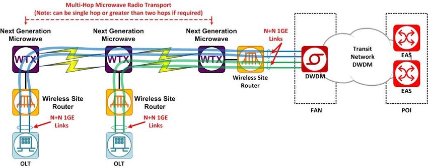
Network Design Rules

Contents

1   Introduction                                                                                     9

2   Network Design                                                                                  11

    2.1   High Level Design Overview                                                                11

    2.2   Fibre (GPON) Access Domain                                                                13

          2.2.1    GPON NTD (ONT)                                                                   13

          2.2.2    Fibre Network                                                                    14

                   2.2.2.1   Fibre                                                                  14

                   2.2.2.2   Distribution Fibre Network - Star                                      18

                   2.2.2.3   Distribution Fibre Network - Loop                                      19

                   2.2.2.4   Flexibility Joint Location                                             22

                   2.2.2.5   Fibre Distribution Hub                                                 22

                   2.2.2.6   Skinny Local Fibre Network                                             23

                   2.2.2.7   Local Fibre Network                                                    27

                   2.2.2.8   Customer RF injection points                                           31

                   2.2.2.9   Optical Budget                                                         32

          2.2.3    Optical Line Terminator                                                          33

          2.2.4    Fibre Access Planning Hierarchy                                                  33

                   2.2.4.1   Fibre Access Planning Hierarchy – post Multi Technology Mix            33

                   2.2.4.2   Fibre Access Planning Hierarchy – pre Multi Technology Mix             33

    2.3   Point to Point Fibre Access Domain                                                        37

          2.3.1    Ethernet NTD                                                                     37

          2.3.2    Fibre                                                                            38

                   2.3.2.1   Distribution Fibre Network                                             38

                   2.3.2.2   Fibre Distribution Hub/Flexibility Joint                               38

    2.4   Copper Access Domain                                                                      38

          2.4.1    Network Connection Device                                                        39

          2.4.2    Copper Plant                                                                     39

          2.4.3    Distribution Point Unit (DPU)                                                    39

          2.4.4    DSLAM                                                                            40

          2.4.5    Fibre Network                                                                    40

          2.4.6    Optical Line Terminator (OLT)                                                    41

                                   © 2019 nbn co limited | ABN 86 136 533 741              Page 3 of 84
Network Design Rules

   2.5    HFC Access Domain                                                               41

          2.5.1   HFC NTD (Cable Modem)                                                   41

          2.5.2   Coax Plant                                                              42

          2.5.3   HFC Optical Node                                                        42

          2.5.4   Fibre Network (FN)                                                      42

          2.5.5   RF Transmission                                                         42

          2.5.6   RF Combiner                                                             42

          2.5.7   HFC Transport                                                           42

          2.5.8   Cable Modem Termination System (CMTS)                                   42

   2.6    The MTM Fixed Access Network Planning Hierarchy                                 43

   2.7    TD-LTE Wireless Access Domain                                                   45

          2.7.1   Wireless NTD (WNTD)                                                     46

          2.7.2   Radio Spectrum                                                          46

          2.7.3   eNodeB (Base Station)                                                   47

          2.7.4   Aggregation and Transport for Wireless                                  47

                  2.7.4.1      Microwave Transport Equipment                              47

                  2.7.4.2      Fibre Transport Equipment                                  48

                  2.7.4.3      Transport                                                  48

                  2.7.4.4      POI Aggregation Switch                                     48

          2.7.5   Packet Data Network Gateway (PDN-GW)                                    48

          2.7.6   Wireless Access Planning Hierarchy                                      49

   2.8    Satellite Access                                                                50

          2.8.1   Satellite NTD (Very Small Aperture Terminal (VSAT))                     51

          2.8.2   Satellite                                                               51

          2.8.3   RF Sub-System                                                           53

          2.8.4   VSAT Baseband Sub-System                                                53

          2.8.5   Business Satellite Services VSAT Baseband Sub-System                    54

          2.8.6   Satellite GW Routing and Switching                                      54

          2.8.7   BSS Satellite GW Routing and Switching                                  54

          2.8.8   Service Connectivity Network                                            54

          2.8.9   Service Control                                                         54

          2.8.10 BSS Satellite POI Routing, Switching & Security                          54

          2.8.11 BSS Hosting Infrastructure                                               54

                                    © 2019 nbn co limited | ABN 86 136 533 741   Page 4 of 84
Network Design Rules

          2.8.12 Satellite Planning Hierarchy                                                               55

   2.9    Transport Domain                                                                                  56

          2.9.1   Dense Wavelength Division Multiplexing (DWDM)                                             56

                  2.9.1.1    Standard Reconfigurable Optical Add-Drop Multiplexers (ROADMs)                 57

                  2.9.1.2    Colourless Directionless Reconfigurable Optical Add-Drop Multiplexers (CD-
                             ROADMs)                                                                        57

                  2.9.1.3    Optical Line Repeaters (OLRs)                                                  57

                  2.9.1.4    DWDM Network Topologies                                                        57

          2.9.2   Managed Services Transmission                                                             61

          2.9.3   Direct Fibre                                                                              63

          2.9.4   Microwave Backhaul                                                                        64

          2.9.5   Access Aggregation Switch (AAS)                                                           65

   2.10 Aggregation Domain                                                                                  65

          2.10.1 Ethernet Aggregation Switch (EAS)                                                          66

          2.10.2 Ethernet Fanout Switch (EFS)                                                               67

          2.10.3 Ethernet Combined Switch (ECS)                                                             68

          2.10.4 Aggregation Domain and POI Architecture                                                    69

   2.11 Service Connectivity Network Domain                                                                 71

          2.11.1 ETS to ETS Connectivity                                                                    71

          2.11.2 ETS to Satellite RFGW Connectivity                                                         72

          2.11.3 ETS to DPC Connectivity                                                                    72

          2.11.4 ETS to ECS Connectivity                                                                    73

          2.11.5 ETS to EAS Connectivity                                                                    74

          2.11.6 ETS to EFS Connectivity                                                                    74

Appendix A        Definitions                                                                               76

Appendix B        Document Control                                                                          81

   B.1    Prudent Design Condition [Clause 1D.6 of SAU]                                                     81

   B.2    Permitted Variation Category [Clause 1D.7.2 of SAU]                                               81

   B.3    Update to the Network Design Rules [Clause 1D.7.4(a) of SAU]                                      82

   B.4    Substantive Changes to Network Design Rules since June 2018                                       83

   B.5    Non-substantive Changes to Network Design Rules since June 2018                                   83

                                 © 2019 nbn co limited | ABN 86 136 533 741                        Page 5 of 84
Network Design Rules

Figures
Figure 1 Target High Level Architecture Context Diagram ......................................................................... 12

Figure 2 Focus of this Document ........................................................................................................... 13

Figure 3 Ribbon Fibre .......................................................................................................................... 15

Figure 4 Connector and Multi-port Connections ....................................................................................... 15

Figure 5 Example Star DFN Logical Connectivity ...................................................................................... 19

Figure 6 Traffic paths available when failure occurs ................................................................................. 20

Figure 7 Traffic paths available when failure occurs on return spur ............................................................ 21

Figure 8 Flexibility Joint Location ........................................................................................................... 22

Figure 9 FDH PON Connection ............................................................................................................... 23

Figure 10: BJL Aggregation Utilisation example for FTTP and FTTC ............................................................ 24

Figure 11: FSL Aggregation example for FTTP ......................................................................................... 24

Figure 12: Point to point MDU architecture example for FTTP .................................................................... 25

Figure 13: MDU Cascade Architecture example 1 for FTTP ........................................................................ 26

Figure 14: MDU Cascade Architecture example 2 for FTTP ........................................................................ 26

Figure 15: MDU Cascade Architecture example 3 for FTTP ........................................................................ 26

Figure 16: MDU Cascade Architecture example 4 for FTTP ........................................................................ 27

Figure 12 DA Module Hierarchy ............................................................................................................. 28

Figure 13 MDU Fibre Demand
Network Design Rules
Figure 23 Fibre Serving Area (FSA) ....................................................................................................... 37
Figure 24 Point to Point Connection using DFN ........................................................................................ 38
Figure 25 4 Port DPU with fibre connectivity ........................................................................................... 40
Figure 27 High level interconnection block diagram of HFC Access ............................................................. 41
Figure 28 High level interconnection block diagram of Wireless Access ....................................................... 46
Figure 29 Microwave Transport Design ................................................................................................... 48
Figure 30 An example Wireless Serving Area Module ............................................................................... 49
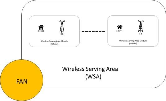
Figure 31 An example Wireless Serving Area .......................................................................................... 50
Figure 32 High level interconnection block diagram of Satellite Access ....................................................... 51
Figure 33 Design of User Spot Beams .................................................................................................... 52
Figure 34 Basic DWDM physical connectivity scenarios ............................................................................. 56
Figure 35 Standalone physical rings ...................................................................................................... 58
Figure 36 Examples of redundancy in the DWDM network (using 1+1 Client Protection and 1+1 Service
Protection) ......................................................................................................................................... 59
Figure 37 Overlapping physical rings ..................................................................................................... 59
Figure 37 Use of CD-ROADM capability to increase path options ................................................................ 60
Figure 38 Point-to-point spur links ........................................................................................................ 61
Figure 39 Point-to-point standalone links ............................................................................................... 61
Figure 40 Fibre access transit ............................................................................................................... 62
Figure 41 Unprotected Greenfields fibre access transit ............................................................................. 62
Figure 42 Wireless access transit .......................................................................................................... 63
Figure 42 Microwave Backhaul Example ................................................................................................. 64
Figure 26 AAS Interfaces .................................................................................................................... 65
Figure 43 Aggregation Domain interfaces on the EAS............................................................................... 66
Figure 44 Aggregation Domain interfaces on the EFS ............................................................................... 67
Figure 45 E-NNI Mode A connection model from an Access Seeker Provider Edge (AS PE) ............................ 67
Figure 46 E-NNI Mode B connection model from a single AS PE ............................................................... 68
Figure 47 E-NNI Mode B connection model from two AS PEs ..................................................................... 68
Figure 48 Aggregation Domain interfaces on the ECS .............................................................................. 69
© 2019 nbn co limited | ABN 86 136 533 741 Page 7 of 84Network Design Rules
Figure 49 Two tier aggregation architecture............................................................................................ 70
Figure 50 One tier aggregation architecture ............................................................................................ 71
Figure 51 ETS to ETS Physical Connectivity ............................................................................................ 72
Figure 52 ETS to Satellite RFGW Physical Connectivity ............................................................................. 72
Figure 53 ETS to SCS Physical Connectivity ............................................................................................ 73
Figure 54 ETS to ECS (Satellite Central POI) Physical Connectivity ............................................................ 73
Figure 55 ETS to EAS Physical Connectivity ............................................................................................ 74
Figure 56 ETS to EFS Physical Connectivity ............................................................................................ 75
Tables
Table 1 Summary of fibre & connector types used in the network .............................................................. 17
Table 2 Fibre Standards Reference Code ................................................................................................ 18
Table 3 Maximum Optical Loss .............................................................................................................. 33
Table 4 12 FDH FSAM Fibre Requirements per FDH ................................................................................. 36
Table 5 Copper DSLAM Node Deployment Options ................................................................................... 40
Table 6 Example of Planning Hierarchy .................................................................................................. 45
Table 7 RF Spectrum Plan .................................................................................................................... 53
Table 8 Acronyms, Terms and Definitions ............................................................................................... 80
Table 9 Substantive Changes to NDRs since June 2018 ............................................................................ 83
Table 10 Non-substantive changes to NDRs since June 2018 .................................................................... 84
© 2019 nbn co limited | ABN 86 136 533 741 Page 8 of 84Network Design Rules
1 Introduction
These Network Design Rules (NDRs) provide an overview of the current physical network architecture and high
level design of nbn co limited’s (nbn’s) network and network components. The NDRs are linked to nbn’s
Special Access Undertaking (SAU) – the initial version of the NDRs (dated September 2012) satisfied the
requirements of clause 1D.7.1 upon commencement of the SAU on 13 December 2013. This updated version of
the NDRs builds on previous updates provided to the ACCC, and satisfies the requirements of clause 1D.6,
1D.7.2 and 1D.7.4 (which relates to how the NDRs will be updated over time).
On 24 August 2016, the Shareholder Ministers provided nbn with a new Statement of Expectations (24 August
SoE), which replaced all previous Statements and contained changes compared with previous Statements
provided to it. One of those changes related to the requirement for nbn to be mindful of certain market-based
principles. In particular, the 24 August SoE included the following key statements:
“This statement provides guidance to nbn to help ensure its strategic direction aligns with the
Government’s objectives for the delivery of the network. This statement provides nbn with flexibility
and discretion in operational, technology and network design decisions, within the constraints of the
Equity Funding Agreement with the Commonwealth, and the Government’s broadband policy
objectives...
…
Broadband policy objectives
The Government is committed to completing the network and ensuring that all Australians have access
to very fast broadband as soon as possible, at affordable prices, and at least cost to taxpayers. The
Government expects the network will provide peak wholesale download data rates (and proportionate
upload rates) of at least 25 megabits per second to all premises, and at least 50 megabits per second
to 90 per cent of fixed line premises as soon as possible. nbn should ensure that its wholesale services
enable retail service providers to supply services that meet the needs of end users.
To achieve these objectives nbn should roll out a multi-technology mix network and build the network
in a cost effective way using the technology best matched to each area of Australia. nbn will ensure
upgrade paths are available as required.
nbn should pursue [the broadband policy objectives] and operate its business on a commercial basis.
In doing so nbn should be mindful of the following principles:
- Rolling out the network: When planning the rollout, nbn should prioritise locations that are
poorly served, to the extent commercially and operationally feasible. During the rollout, nbn should
be guided by the following goals: service quality and continuity for consumers; certainty for retail
service providers and construction partners; and achievement of rollout objectives as cost-
effectively and seamlessly as possible. nbn should apply the Government’s new developments
policy.
- Vehicle for market reform: The Government expects the network to be a wholesale only access
network, available to all access seekers, that operates at the lowest practical level in the network
stack. The completion of the network will enable the structural separation of Telstra and a more
competitive market for retail broadband and telephony services. nbn should retain optionality for
future restructuring or disaggregation.
- Market environment: nbn is a commercial entity operating in a market environment and can
compete and innovate like other companies in this environment in accordance with legal and policy
parameters.
© 2019 nbn co limited | ABN 86 136 533 741 Page 9 of 84Network Design Rules
- Funding: Taxpayers have made a substantial investment in nbn. The Equity Funding Agreement
imposes a cap on the maximum amount of equity funding that will be provided by the Government.
nbn needs to remain disciplined in its operations, proactively managing costs to minimise funding
requirements and working with the Government to optimise its capital structure.
- …”
In accordance with the 24 August SoE, nbn will continue to plan and design its network to pursue the
Government’s broadband policy objectives, while operating on a commercial basis and being mindful of the
market principles set out above.
The NDRs now include the network design for FTTx (including Fibre to the Premises (FTTP) (GPON), Fibre to the
Node (FTTN), Fibre to the Building (FTTB) and Fibre to the Curb (FTTC)), Hybrid Fibre Coax (HFC), TD-LTE
Wireless, Satellite Access, Transport and Aggregation network domains.
The NDRs have been updated in accordance with clause 1D.7.4 of the SAU to reflect the ongoing development
of, and changes to, nbn’s network architecture since nbn’s last update. This includes (amongst other things)
changes to the network design to account for the ongoing targeted augmentation of the Transport network to
improve service availability and the development of G.Fast capability to support greater speed services in the
future.
nbn will continue to update the NDRs to take account of variations, augmentations or enhancements to the
design, engineering and construction of nbn’s network. This will include upcoming changes to nbn’s network to
account for the launch of Sky Muster Plus and the Business Satellite Service.
An itemised summary of the substantive changes made in this updated version of the NDRs relative to the June
2018 version is provided in Appendix B.
A list of non-substantive changes is also now provided in Appendix B, which covers refinements, clarifications
and corrections to this document.
© 2019 nbn co limited | ABN 86 136 533 741 Page 10 of 84Network Design Rules
2 Network Design
2.1 High Level Design Overview
The nbnTM network has been divided into domains to allow for communication of the overall solution.
The target high level architecture is shown in Figure 1. This view includes the IT platforms, which are out of
scope for this High Level Design, but must be interfaced to, to achieve a complete working solution. The target
high level architecture is expected to continue to evolve over the coming years as nbn continues to evolve and
refine its network design.
The focus of this document is captured in Figure 2. These are the domains for Fibre (GPON), Copper, HFC, LTE
Wireless and Satellite.
The high level domains and their functions are as follows:
Network: Key function is the carriage of customer traffic
o Access: Various technology solutions to allow End Users to be connected to the nbnTM network.
The long term technology domains covered by the NDRs are Fibre (GPON), Copper (VDSL),
HFC, Wireless (LTE) and Satellite.
o Transport: Provides transparent connectivity between network elements
o Aggregation: Takes many interfaces from network elements and aggregates them for
presentation on fewer interfaces back into network elements and vice versa. Also provides the
point of interconnect for access seekers, the customers of nbnTM services.
o Service Connectivity Network (SCN): Is the core IP/MPLS network and provides service
connectivity for satellite access (RF Gateway to DPC and DPC to satellite central POI site) and
flexibility of connectivity within the Aggregation network for support of HFC.
National Connectivity Network: network that does not carry the Access Seeker to/from End User traffic.
This network carries OA&M related traffic and signalling traffic.
Network Management: Systems that support the network carrying the customer service traffic. Functions
include element management, time information, Authentication, Authorisation and Accounting (AAA) for
access to network elements and connectivity between the equipment providing Network Management
functions and the Network Elements themselves
Control: those required to operate in real time (or very near real time) to support the establishment of an
End User connection through to the Access Seeker
Lawful Interception: support the delivery of replicated customer traffic to Law Enforcement Agencies as
legally required by the Telecommunications (Interception and Access) Act 1979.
IT Platforms: Platforms supporting systems required for providing a customer portal, order acceptance,
enforcement of business rules (e.g. number of active data services per NTD), activation, fulfilment,
assurance and billing. Also includes systems required to interact with Element Management systems to
operate the network carrying the customer traffic.
© 2019 nbn co limited | ABN 86 136 533 741 Page 11 of 84Network Design Rules
IT Platforms/Application Capabilities Access
Seekers
Resource Management Portal & Online Services Assurance
(Service
Management)
Enterprise Information Management AS 1
Business & Financial Management Fulfilment & LNI
Security Management
AS 2
Wireless Network Lawful Network Management Control
Management Interception NW Support Wireless Signalling
Element Management Systems
(Vendor Located) Systems
Satellite Wireless
Core (LTE)
OSS-RC
GPON & HSS-FE
LI Management TTAC (LTE) DSL
I&AM NTP SO-EM SAPC-FE CUDB
NW Support System VSAT NMS
NetOP AMS
MME SGw/PGw
Systems Syslog Site EMA SDC
Manager HFC RDM
DNS AAA NoC
DOCSIS Apps Security LAN
SSH GSS
PKI Bastion DOMS NCN
NTS
Security LAN NCN EMS
PG
DNS Avamar AMA Satellite Signalling
Transport Security LAN
Aggregation
DHCP ASN-GW
LI Mediation Patrol/ OOB TNMS SAM
Proactive Terminals AAA DPC
System NW SS Subsystem
Optima
OOB Edge NCN Core
Transport for NCN
End Network
Users
Access SCN Aggregation
CPE NTD eNodeB Wireless (LTE) PDN GW Ethernet Trunking
Agg regation & Transport for Wireless A ccess Ethernet Ethernet
Aggregation Fanout
CPE NTD Satellite RF Gateway DPC/BSS POI
Transport
Satellite Agg & Transport for Satellite Acce ss
DWDM
CPE NTD Fibre FDH/FJL OLT
Fibre Network Fibre Network Access
Seekers
CPE NTD HFC (DOCSIS) Optic Node CMTS Direct Fibre (End User
Coax Fibre Network RF Tx, Combiner &
Transport
Traffic)
AS 1
Copper (xDSL) DSLAM AAS
Modem Copper Fibre Network AS 2
Micrwave Backhaul
NCD DPU Copper/Fibre FDH/FJL OLT
3rd Party Managed Service
CPE Copper Fibre Network Fibre Network
Figure 1 Target High Level Architecture Context Diagram
© 2019 nbn co limited | ABN 86 136 533 741 Page 12 of 84Network Design Rules
End Network
Users
Access SCN Aggregation
CPE NTD eNodeB Wireless (LTE) PDN GW Ethernet Trunking
Agg regation & Transport for Wireless A ccess Ethernet Ethernet
Aggregation Fanout
CPE NTD Satellite RF Gateway DPC/BSS POI
Transport
Satellite Agg & Transport for Satellite Acce ss
DWDM
CPE NTD Fibre FDH/FJL OLT
Access
Fibre Network Fibre Network Seekers
CPE HFC (DOCSIS) Optic Node Direct Fibre (End User
NTD CMTS
Traffic)
RF Tx, Combiner &
Coax Fibre Network Transport
AS 1
Copper (xDSL) DSLAM AAS
AS 2
Modem Copper Fibre Network
Micrwave Backhaul
NCD DPU Copper/Fibre FDH/FJL OLT
3rd Party Managed Service
CPE Copper Fibre Network Fibre Network
Figure 2 Focus of this Document
The nbnTM physical network architecture is designed to provide the required connectivity for nbnTM services
whilst allowing for the required level of availability and resiliency in an efficient manner.
Each domain has a set of physical network elements that deliver the functionality and interfaces to support the
nbnTM services.
2.2 Fibre (GPON) Access Domain
The Fibre (GPON) access domain solution consists of the following components:
GPON NTD (ONT) - The Optical Network Terminal located at the end-user premises uses GPON technology
to extend optical cable from an OLT shelf. It delivers UNI-V and UNI-D capabilities to a premises.
Fibre Network (FN) provides optical pathways between the GPON NTD and OLT. Sections of the Fibre
Network are shared by other access domains.
OLT - The Optical Line Terminal provides FAN Site processing, switching, and control functions. The OLT
aggregates GPON networks into a number of network-facing 10Gbps links.
2.2.1 GPON NTD (ONT)
The GPON NTD terminates the incoming physical fibre at the end-user premises and provides one or more User
to Network Interfaces (UNI). A number of GPON NTD varieties will be used to suit different circumstances, end-
user types and interface quantities. The variants included are Indoor and Outdoor Single Dwelling GPON NTDs.
Both have the following:
1 x GPON fibre interface
2 x UNI-Voice interfaces
4 x UNI-Data interfaces
Support for standard power supply or Uninterruptable Power Supply (UPS)
Indoor GPON NTD variants should be wall mounted inside the nbnTM GPON NTD enclosure. Outdoor GPON NTD
variants will be permanently fixed to a surface (e.g. interior or exterior wall).
© 2019 nbn co limited | ABN 86 136 533 741 Page 13 of 84Network Design Rules
The GPON NTD enclosure combines mounting for a GPON Indoor NTD and a standard power supply with fibre,
power and End User service cable management.
There are two basic types of power supply available for each GPON NTD variant; AC to DC standard power
supply or power supply with backup. The standard power supply accepts ~240 VAC input and provides 12 VDC
towards the GPON NTD via a specialised cable with captive connectors (indoor GPON NTD).
The power supply with backup also accepts ~240 VAC input but includes a battery facility for providing 12 VDC
towards the GPON NTD even during an AC mains failure event, until the battery falls below the minimum
energy capacity. DC power is fed to the GPON NTD via a specialised cable with captive connectors (indoor
GPON NTD) or screw terminals (outdoor GPON NTD), the cable also allows for simple power related alarms to
be forwarded from the UPS unit to the GPON NTD.
The UPS can be installed with or without a battery, allowing an Access Seeker or end-user to provide a battery
at a later date, and perform maintenance of the battery facility without requiring nbn involvement. When there
is no battery installed, the UPS operates like a regular AC to DC power supply.
Both the AC to DC power supply and UPS must be installed indoors. When installed with an Outdoor GPON NTD,
the power cabling must extend within the premises to the power supply or UPS.
2.2.2 Fibre Network
The NBN Co Fibre Network provides the physical connectivity between the FAN site and the active equipment in
the street or building.
The passive network component of a fixed network build comprises a significant part of the overall fixed
network deployment. It is generally disruptive and expensive to augment or modify so it is important that the
architecture, planning, design, and installation accommodates the long term needs and future growth and
capacity. It is nbn’s aspiration that these facilities will be suitable not only for the nbnTM network’s initial
technology choice, but for fixed access technologies developed in the future, whatever they may be.
In order to provide a functional and operational network a high degree of uniformity of the passive
infrastructure is desirable. Uniformity of design and construction facilitates education and training, the
availability of competent staff, and economies of scale and efficiencies in the supply industry in general.
Regionalised or localised variations in design or construction practices will be minimised where practical as
these differences may disadvantage the affected communities due to the increased costs and complexity of
managing variations in technical and operational processes.
The NBN Co Fibre Network includes the Distribution Fibre Network (DFN), the Local Fibre Network (LFN) and
Premises Fibre Networks (PFN). The DFN provides the connectivity from the Fibre Aggregation Node (FAN) to
the first point where individual fibres can be accessed for a Distribution Area (refer to 2.2.4.1 for description of
a Distribution Area). The LFN provides the connectivity from this point towards the premises. The PFN provides
the connectivity from the street through to the premises. There are currently two DFN architectures: Loop and
Star. Star DFN deployments will be the default design used for all fixed access networks, providing a more cost
effective solution. There are also two LFN architectures: LFN and Skinny LFN.
The common denominator of this network is the actual physical fibre strands. nbn has selected ribbon fibre
technologies due to the cost and labour savings associated with the use of this technology where high fibre
numbers are required. The Skinny LFN uses lower fibre count cables with stranded fibres. All fibres are
accessible individually. This provides greater flexibility in relation to the deployment of the LFN.
2.2.2.1 Fibre
Ribbon Fibre
© 2019 nbn co limited | ABN 86 136 533 741 Page 14 of 84Network Design Rules
Ribbon fibre technology significantly increases the fibre cable core counts available, and also provides
significant time savings when joining fibres via fusion splicing when compared to stranded or single fibre
particularly where fibre counts are greater than 144. Ribbon fibre cables are available with fibre counts ranging
between 12 and 864 fibres, and these are virtually identical in size and handling characteristics to similarly
constructed single fibre cables.
Figure 3 Ribbon Fibre
The cables match the core counts required where all premises require a fibre as part of the access solution (12,
72, 144, 288, 432, 576, and 864) and the 12 fibre matrix suits the modularity of the Factory Installed
Termination Systems (FITS). The FITS is a pre-connectorised system which pre-terminates fibres in the Local
Fibre Network onto multi-fibre connectors in groups of 12 and multi-ports are then connected into these as
required.
Figure 4 Connector and Multi-port Connections
Stranded Fibre
The stranded fibre cable permits access to individual fibres which in turn allows for a greater degree of
flexibility within the LFN. For example, a geographic area may require an allocation of x fibres for an FTTN node
+ x fibres for FTTB, + x fibres for Fibre on Demand. This requirement to allocate fibres initially and also
provides flexibility for in-fill allocation. It allows for access to the fibre on an individual strand level to permit
them to be manipulated individually as opposed to groups of 12 fibre ribbons.
The following table provides a summary view of what fibre types and connectors are used in the network:
© 2019 nbn co limited | ABN 86 136 533 741 Page 15 of 84Network Design Rules
Network Fibre Type Connectors Standards Reference
(see Table 2 below)
DFN - Ribbon Splice: 36 fibres (3 ribbons) per FDH. 2 ribbons All Fibre Optic Cable
Loop spliced, 1 spare
Splice: 288 fibre to multiple TFANs
Splice: 72 fibre to single TFAN
DFN - Ribbon Splice: 12 fibres (1 ribbon) per Distribution All Fibre Optic Cable
Star Area. DFN trunk cable has >33% spare capacity
(for in-fill growth, and to support future
technology and product directions)
Splice: Input tail or individual fibres at a node
(e.g. FTTN Cabinet)
LFN Ribbon Splice: FDH (72) Tail to factory installed patch All Fibre Optic Cable
panel
Connector: FDH Patching = SC/APC
Splice: FDH Tail (e.g. 576) to Multiport Tail (12)
Connector: Multiport tail = 12 fibre tether
optical connector (proprietary format)
Connector: Multiport Single Customer
Connection = single fibre optical connector
(proprietary format)
LFN Ribbon – Splice: FDH Tail (e.g. 576) to Aerial Cable All Fibre Optic Cable
Aerial Splice: Aerial Cable to Multiport Tail (12)
Connector: Multiport tail = 12 fibre tether
optical connector (proprietary format)
Connector: Multiport Single Customer
Connection = single fibre optical connector
(proprietary format)
LFN - Stranded Splice: 12 fibre ribbon splice at DJL to FSD All Fibre Optic Cable
skinny (Flexibility Sheath Distribution), FSD installed
into FJL (Flexibility Joint Location) and fibre de-
ribbonised.
Splice: Individual FSD fibres spliced to 1, 4, or
12 fibre stranded cables
Splitter: Individual FSD fibres spliced to 1st
stage passive splitter, outgoing splitter tails
spliced to 1, 4, or 12 fibre stranded cables
(FLS).
Splitter: Individual FSL fibres spliced to 2nd
stage passive splitter, outgoing splitter tails
spliced to 1 fibre SSS cables.
Connector: Multi-port Tail or Equipment Tail
(Hardened), single fibre connector.
© 2019 nbn co limited | ABN 86 136 533 741 Page 16 of 84Network Design Rules
Splitter: Connection to 3rd stage optical splitter
(an example use of this is uplift from FTTC to
FTTP)
Connector: Multiport Single Customer
Connection = single fibre optical connector
(proprietary format)
LFN - Ribbon - Splice: 12 fibre ribbon splice at DJL to FSD All Fibre Optic Cable
skinny Aerial (Flexibility Sheath Distribution), FSD installed
into FJL (Flexibility Joint Location) and fibre de-
ribbonised (1:2 for FTTC, 1:4 or 1:8 for FTTP)
FJL to aerial BJL 12 f stranded (1:1 or 1:4 split)
Splice FTTP: Aerial cable to Splitter Multiport
Tail (1)
Splice FTTC: Aerial cable to DPU (1)
PFN – Single Splice: Single Fibre Fusion Splice to PCD & FWO All Fibre Optic Cable +
SDU Fibre Drop
Fibre Optic Single
Drop Cable
Multiport Feeder
Cable
PFN – Ribbon Splice: PDH,FDT tail ,FWO All Fibre Optic Cable +
MDU Connector: PDH,FDT,FWO,NTD = SC/APC
Fibre Optic Aerial
Connector: FDT,FCD = MPO/APC
Cable
PFN – Single Splice: Single Fibre Fusion Splice to PCD All Fibre Optic Cable +
MDU Fibre Drop
Fibre Optic Single
Drop Cable
Table 1 Summary of fibre & connector types used in the network
Standards Reference Code Title / Description
All Fibre Optic Cable
Characteristics of a Single Mode Optical Fibre and Cable, Table 4
ITU-T G.652
G.652-G.652D attributes.
Bend-insensitive single-mode fibres for access networks and
ITU-T G.657
customer premises, Table A2
GR-20-CORE Generic Requirements for Optical Fibre and Optical Fibre Cable
IEC 60793 Optical Fibres
IEC 60794 Optical Fibre Cables
© 2019 nbn co limited | ABN 86 136 533 741 Page 17 of 84Network Design Rules
Standards Reference Code Title / Description
AS1049 Telecommunication Cables-Insulation, sheath, and jacket
Fibre Optic Aerial Cable
IEEE 1222 Standard for All Dielectric Self Supporting Aerial Fibre Optic Cable
GR-3152 Generic Requirements of Hardened Multi-Fibre Optical Connectors.
GR-3122 Generic Requirements for a Factory Installed Termination System.
GR-771 Generic Requirements for Fibre Optic Splice Closures
Fibre Optic Single Drop Cable
Characteristics of a Bending Loss Insensitive Single Mode Optical
ITU-T G.657
Fibre and Cable, Table A2
GR-3120 Generic Requirements of Hardened Fibre Connectors.
Multiport Feeder Cable
GR-3152 Generic Requirements of Hardened Multi-Fibre Optical Connectors.
Multiport
GR-771 Generic Requirements for Fibre Optic Splice Closures
GR-3152 Generic Requirements for Hardened Multi-Fibre Connectors
GR-3120 Generic Requirements for Hardened Fibre Connectors.
MPO / APC
GR1435 Generic Requirements for Multi Fibre Optical Connectors
Table 2 Fibre Standards Reference Code
2.2.2.2 Distribution Fibre Network - Star
The Distribution Fibre Network (DFN) provides the underground fibre pathways between the FAN sites and the
first point where individual fibres can be accessed for each Access Distribution Area.
The Star DFN topology is the default for the Fixed Access build (post-Multi Technology Mix) to achieve cost
efficiencies in construction.
A Star DFN topology starts from a FAN site and extends outwards, with nodes connecting into it along its
length. The Star architecture results in the fibre path for nodes being unprotected.
The DFN is routed to pass near the likely node locations without requiring significant construction works.
The Star DFN is considered to comprise five segment types:
Distribution Sheath Segment (DSS) - Aggregation
Distribution Sheath Segment (DSS) - Trunk
Distribution Sheath Segment (DSS) - Branch
Distribution Sheath Segment (DSS) - Feeder
© 2019 nbn co limited | ABN 86 136 533 741 Page 18 of 84Network Design Rules
Hub Sheath Distribution (HSD)
Figure 5 illustrates the logical connectivity principles for DSS Aggregation, Trunk, Branch, Feeder and HSD
configurations.
Branch Multiport HSD
d er Serving
Fee 12f Node Area
12 S
DFN Closure f DS 12f Module
1
* Where required
Branch *
72f
DSS
DSS 288f 288f DSS Trunk
Aggregation *
FAN 576f
288f DSS Trunk
f DS 12f
12 SF
ee 12f Node
de
r HSD
Serving
Area
Module
2
Figure 5 Example Star DFN Logical Connectivity
DFN Connectivity
The DFN is preferably installed underground, and by exemption aerially.
The DFN provides connectivity to the nodes located within the SAM modules (refer to Figure 5).
Multiple cables from different DFN cables can share the same duct-line, as well as sharing duct-lines with TFN
and LFN cables.
Nodes are connected to the DFN cables and each node is allocated multiples of 12 fibres towards the FAN site.
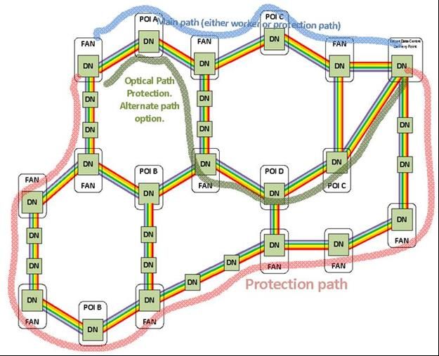
2.2.2.3 Distribution Fibre Network - Loop
The Distribution Fibre Network (DFN) provides the underground fibre pathways between the FAN sites and the
first point where individual fibres can be accessed for an Access Distribution Area. The DFN has previously been
installed primarily for the support of GPON in a loop topology, starting from a FAN site and finishing at the
same site, with FDHs connecting into it along its length. In this configuration, the DFN cables are typically
higher fibre counts, with fibre core counts needed between 288 to 864 fibres. The DFN is also notionally
allocated an A and B direction to assist in the identification of upstream connections at the FDH, where the A
indicates a clockwise direction and B an anticlockwise direction.
© 2019 nbn co limited | ABN 86 136 533 741 Page 19 of 84Network Design Rules
The FDHs are street side externally rated cabinets which are used to house the GPON splitters used to facilitate
connectivity between the DFN and the Local Fibre Network (LFN). The FDH also provides the ability to provide
direct connectivity between the DFN and LFN.
The DFN was also required to provide diverse pathways for point to point services from FDHs where required.
The DFN fibre links cable into the FDH is provided by a single cable and has both A and B directions within the
same cable sheath.
DFN Diversity
The FTTP network has been extensively modelled for availability percentages and expected downtime due to
faults and this modelling has recognized that the DFN has a significant input into the availability calculations.
This is the direct effect of the high fibre counts and distances required for the DFN.
The availability target indicates that a link distance of 4500 metres can be applied to a single connection
pathway between the FAN and the farthest FDH or to a spur off the DFN without the need to provide diversity.
For practical purposes this distance is reduced to 4000 metres to account for unforeseen alterations to the
network in the construction phase and to provide flexibility for future maintenance.
This calculation allows the DFN to be installed in topologies other than fully diverse.
The default position for the DFN was to provide connection diversity to each FDH for the provision of diverse
services and to provide the capability for a quicker Mean Time to Repair (MTTR). The quicker MTTR is achieved
through the use of the diverse path available at the FDH to move affected services to the other “side” of the
DFN effectively bypassing the affected cable link.
FDH FDH
3 4
“A” Direction FDH FDH FDH FDH
1 2 5 6
FAN
FDH FDH FDH FDH
“B” Direction 12 11 8 7
FDH FDH
10 9
Direction of traffic to FDH 4 before failure
Change in direction of traffic to FDH 4 after failure
Figure 6 Traffic paths available when failure occurs
An alternate position is for a collapsible loop (referred to as a return spur) to be installed from the main diverse
DFN, up to 4000 metres, with a maximum of 2 FDHs connected into the return spur. This topology does not
permit service restoration patching for the two connected FDHs when the return spur is interrupted but does
allow for restoration patching for the remainder of the DFN.
© 2019 nbn co limited | ABN 86 136 533 741 Page 20 of 84Network Design Rules
FDH
5
FDH
5
One cable sheath
FDH FDH
3 4
Direction of traffic to FDH 4 before failure
Change in direction of traffic to FDH 4 after failure
Figure 7 Traffic paths available when failure occurs on return spur
Another deployment option is for a spur in which only one pathway (either A or B and referred to as a single
spur) is presented to the FDHs.
DFN Connectivity
The DFN is preferably installed underground, and by exemption aerially, and in the past was designed in a ring
topology starting and finishing at the same FAN site. This effectively divided the DFN cable ring into an ‘A’ and
a ‘B’ side.
The DFN provides connectivity to the Fibre Distribution Hubs (FDH) located within the FSAM modules and
provides two diverse fibre pathways back into the FAN site for each FDH (refer to Figure 6).
Any individual DFN ring cable will be separated from any other portion of the same ring by the most practically
achievable distance. Multiple cables from different DFN ring cables can share the same duct-line, as well as
sharing duct-lines with TFN and LFN cables.
Fibre Distribution Hubs are connected to the DFN ring cables and each FDH is allocated fibres in both A and B
directions towards the FAN site. This ring allocation provides a diverse pathway for end-user connectivity and
allows for temporary service restoration when required. In the event of a serious service impacting event (e.g.
cable cut, etc.) the services that are connected to the affected side can be manually re-patched at the FDH site
and FAN site to the diverse pathway.
Therefore the DFN network must be capable of servicing these connections in both directions of the DFN within
the optical constraints.
Whilst the DFN provides diversity from each FDH this diversity is not transferred into the LFN (the LFN is a star
topology) and therefore the DFN should also be designed to align with potential users of point to point services
(e.g. banks, schools, universities, business parks) to allow the LFN to provide the diverse links.
© 2019 nbn co limited | ABN 86 136 533 741 Page 21 of 84Network Design Rules
2.2.2.4 Flexibility Joint Location
The Flexibility Joint Location (FJL) is an aggregation and connection point between the Distribution Fibre
Network (DFN) and the Skinny Local Fibre Network (LFN). A FJL is used to permit individual fibre access and
management between the incoming DFN and the outgoing Skinny LFN.
Within the FJL are splice trays capable of single fibre management to permit direct splicing between the DFN
and Skinny LFN for all fibre connectivity requirements.
The FJL has a capacity of up to 144 fibre splices and permits multiple configurations of splitters as required for
the DA specific infrastructure. There is no patching facility within the FJL and all fibre connections are spliced.
Extra DFN capacity can be installed into the FJL as required, and a FJL can also be used to connect more FJLs to
the same incoming Flexibility Sheath Distribution (FSD) cable depending on availability of spare fibres.
Split ratios are generally kept to 1:32 with the optical budget being managed to permit greater degrees of
splitting if required for network growth. Splitters may also be reconfigured within the FJL, if required for
capacity.
1 F SSS 1
1 : 4 Spl i t t e r MPT
D
1 S
F
4
S
N
4 S 1 F SSS 1
1 : 8 Spl i t t e r MPT
1 2 F Spl i c e 1 2 F FSD 8
S
S 1 F L SS 1
1 : 3 2 MDU Spl i t t e r
1F S 32
Sp l i c e
1 or 4 f i b r e L SS
S OF/
S
DJ L Cu
DSLAM / FoD
Fl e x i bi l i t y
J oi nt
Loc a t i on
Figure 8 Flexibility Joint Location
2.2.2.5 Fibre Distribution Hub
The Fibre Distribution Hub (FDH) is an aggregation and connection point between the Distribution Fibre
Network (DFN) and the Local Fibre Network (LFN). The FDH is available in 432, 576, and 864 LFN variants,
however 576 has been the preferred choice.
The FDH is an environmentally secure passive device installed on street frontages and serves as a centralised
splitter location. The splitter modules housed within the FDH provide a one-to-many relationship between the
in-coming DFN fibres and the out-going LFN fibres. In keeping with the requirements of the GPON equipment,
the splitters used are a 1:32 passive split.
The standard and most common connectivity type is a PON connection between an end-user and the output leg
of a splitter module.
The splitter module is in a 1:32 planar configuration and these modules are pre-terminated with 1 x DFN
SC/APC fibre lead and 32 x LFN SC/APC fibre leads and these connect into the network via the patch panel
array within the FDH.
© 2019 nbn co limited | ABN 86 136 533 741 Page 22 of 84Network Design Rules
DFN Patch Array
From DFN SC/APC
FAN
1 X DFN IN
1:32 Splitter
32 LFN OUT
1 32
LFN SC/APC To LFN
LFN Patch Array
FDH
Figure 9 FDH PON Connection
2.2.2.6 Skinny Local Fibre Network
The Skinny Local Fibre Network (LFN) is installed from the FJL to the end user premises in a star topology with
no inherent capacity for diversity.
The Skinny LFN architecture is the default for greenfield deployments, and is used to support the multi-
technology mix model to achieve cost efficiencies in construction.
The Skinny LFN is comprised of a 12 fibre ribbon cable for the FJL feeder sheath distribution (FSD) from the
Distribution Joint Location (DJL) and either a single fibre pre-connectorised cable of the Splitter Sheath
Segment (SSS) to connect to SMPs or a Flexibility Sheath Local (FSL) cable containing 4 or 12 Fibres to connect
to Breakout Joint Locations (BJLs).
The FSL cables are used to aggregate the individual SSS cables into either a 4 or 12 fibre stranded fibre cable
in conjunction with a Breakout Joint Location (BJL) to minimise the hauling of multiple SSS cables and provide
high utilisation of existing duct space (see Figure 10).
© 2019 nbn co limited | ABN 86 136 533 741 Page 23 of 84Network Design Rules
1 FIBRE SSS
SMP
1 FIBRE SSS
SMP
FJL 1 FIBRE SSS
SMP
1 FIBRE SSS
SMP
1 FIBRE SSS
SMP
4 or 12 FIBRE 1 FIBRE SSS
FSL SMP
FJL BJL 1 FIBRE SSS
SMP
1 FIBRE SSS
SMP
1 FIBRE SSS
DPU
4 or 12 FIBRE 1 FIBRE SSS
FSL DPU
FJL BJL 1 FIBRE SSS
DPU
1 FIBRE SSS
DPU
Figure 10: BJL Aggregation Utilisation example for FTTP and FTTC
The FSL cables may also be used to connect multiple BJLs to the same sheath with up to 3 BJLs sharing the
same FSL cable and fibres allocated accordingly (see Figure 11).
12 FIBRE FSL BJL BJL BJL
12 FIBRE FSL 12 FIBRE FSL
FJL Fibres Fibres Fibres
1-4 5-8 9-12
Up to 4 x Up to 4 x Up to 4 x
1 FIBRE SSS 1 FIBRE SSS 1 FIBRE SSS
SMP SMP SMP
Up to 4 x SMP Up to 4 x SMP
Figure 11: FSL Aggregation example for FTTP
FTTP: The FJL provides a 1:4 or 1:8 way split, spliced through the BJL. Downstream the SSS cables are used
to connect the Splitter Multi-ports with integrated splitters factory-installed. The Splitter Multi-ports (SMP) used
are commonly 1:8, however 1:4 may be deployed and each variant has a single fibre environmentally hardened
connectorised input with each splitter output leg terminated to another single fibre environmentally hardened
connectorised output.
FTTC: The FJL provides a 1:2 way split, spliced into the BJL. Downstream the SSS cables are used to connect
to 4 port DPUs. The BJL contains a 1:4 optical split and has a single fibre environmentally hardened
connectorised DPU input.
© 2019 nbn co limited | ABN 86 136 533 741 Page 24 of 84Network Design Rules
For aerial deployment, the LFN is a factory installed termination system (FITS) that utilises factory installed
splice closures, referred to as overmoulds, to present the multi-fibre connector at each required location. The
Splitter MPTs and DPUs are then connected in a similar manner as the underground method.
Single Dwelling Unit and Non Addressable Allocations
Each SDU is allocated one port at a SMP in the LFN. This port is utilised for the service connection. An allocation
of 1 spare port per 1:8 SMP is provided and, although allocated, is available for use at the MPT for any non-
addressable connections, extra connections per SDU, etc.
Non-addressable locations can be identified as locations without a physical address, e.g. power transformers,
traffic light controllers, etc.
Any future in-fill or augmentation will be provided on an as needed basis and the LFN expanded accordingly.
Extra ports or fibre may be allocated to provide future capacity. Typically, fibre capacity is held within the FJL
to permit its use anywhere within the DA and for any technology option.
Multi-Dwelling Unit (MDU) Allocations
MDU layouts are varied, and the nbn skinny fibre architecture has been developed to achieve flexibility for the
many and varied topologies encountered.
The physical topology for the MDU architecture is either star (for point to point fibre connectivity), cascade (for
point to multipoint), or a combination of both. The topologies are typically designed in conjunction with each
other as the star topology is also used as an aggregator for the cascade. The Flexibility Joint (FJL) may also be
used to provide the 1st level of cascade, for example, the FJL can provide the 1st level of 1:8 split with 1:4
splitters used within the MDU, depending on topology requirements.
The optical split ratio for GPON FTTP connectivity shall not exceed 1:32 and the PON capacity shall always be
maximised. For example, a single PON can be split first at the FJL and then used to feed 2nd stage splitters
that can appear in MDUs or connected to SMPs or FTTC distribution points.
Star or Point to Point Architecture MDU:
The MDU architecture starts from the Building Fibre Distributor (BFD) which provides a termination and
interconnect location between the incoming fibre cores from the outside plant and the internal termination
devices located deeper within the building structure.
The star topology uses a 12 or 24 fibre pre-connectorised cable and connectorised devices to provide an optical
pathway between the BFD and individual Fibre Distribution Terminals (FDT). The FDT is the connection point for
individual premises cables which are extended between the FDT and termination devices within premises.
Figure 12: Point to point MDU architecture example for FTTP
© 2019 nbn co limited | ABN 86 136 533 741 Page 25 of 84Network Design Rules
Cascade Architecture MDU
The cascade topology is used to connect optical splitters in a serial or cascaded configuration from the BFD
location. The cascaded configuration is limited to the maximum number of serviceable locations per PON. The
terminals used for the connectivity in the building are Splitter Distribution Terminals, which are similar in form
to the FDT however have integrated splitters.
Figure 13: MDU Cascade Architecture example 1 for FTTP
The cascade topology also permits the serial connection of two SDTs to each other, for example, a 1:8 SDT can
be connected to a 1:4 SDT. The cascade configuration also provides an aggregation device via the 1st SDT
connected and if a 1:4 is used as the first level then this device can connect up to 4 X 1:8 SDTs, and if a 1:8 is
used as the 1st level then up to 8 X 1:4 SDTs are connected.
Figure 14: MDU Cascade Architecture example 2 for FTTP
The FDT used in the star or point to point topology may also be used to provide an aggregation point for
multiple cascaded SDTs.
Figure 15: MDU Cascade Architecture example 3 for FTTP
© 2019 nbn co limited | ABN 86 136 533 741 Page 26 of 84Network Design Rules
Figure 16: MDU Cascade Architecture example 4 for FTTP
The FJL may also be used in the cascaded topology to provide the first level of splitting, which is beneficial
when the MDU has a fibre demand that is less than an entire PON or there is a low likelihood of future fibre
connectivity being required.
2.2.2.7 Local Fibre Network
The Local Fibre Network (LFN) is installed from the FDH to the end-user premises in a star topology with no
inherent capacity for diversity. Diversity is achieved by extending the LFN from any other FDH, dependant on
the status of the other FDH’s location in separate geographic pathways.
LFN cables are typically smaller fibre count cables, ranging between 72 and 288 fibre counts, and are installed
in the aerial corridor and underground pathways typically alongside property boundary street frontages. The
LFN cables are presented at the FDH on a connector array to facilitate connection to the upstream DFN either
via a PON splitter or direct connection.
For an underground deployment, the individual LFN cables are extended from the FDH into the Local Fibre
Network to multiple centralised splice closures or Access Joints (AJL) where the cables are joined into smaller
fibre count “tether” cables via splicing. The tether cable is factory terminated on one end only with an
environmentally hardened multi-fibre connector and is installed between the AJL and local fibre pits where they
provide a connection point for the factory terminated Multi-Ports (MPT). Service fibre drops to End User
premises are connected into the MPTs as required.
For aerial deployment, the LFN is a factory installed termination system (FITS) that utilises factory installed
splice closures, referred to as overmoulds, to present the multi-fibre connector at each required location. The
MPTs are then connected in a similar manner as the underground method.
Single Dwelling Unit and Non Addressable Allocations
Each SDU is allocated one fibre in the LFN between the MPT and the FDH. This fibre is utilised for the service
connection. A second fibre is allocated to the same Multiport location that the SDU will connect to and, although
allocated, is available for any use at the MPT for any non-addressable connections, extra connections per SDU,
etc.
Non addressable locations can be identified as locations without a physical address e.g. power transformers,
traffic light controllers, etc.
Extra fibres shall be allocated to provide future capacity. It is recognised that there are different levels of
growth expected across Australia. In areas of low growth, the effective allocation on average is one and a half
fibres per premises. In other areas, the effective allocation on average is three fibres per premises.
© 2019 nbn co limited | ABN 86 136 533 741 Page 27 of 84You can also read