E-BAM PARTICULATE MONITOR OPERATION MANUAL - Met One
←
→
Page content transcription
If your browser does not render page correctly, please read the page content below
E-BAM
                                  PARTICULATE MONITOR
                                   OPERATION MANUAL
                                                  E-BAM-9805 REV E

                    Met One Instruments, Inc.
                    1600 NW Washington Blvd.
                    Grants Pass, OR 97526
                    Telephone: (541) 471-7111
                    Facsimile: (541) 471-7116
                    www.metone.com
E-BAM Particulate Monitor Operation Manual - © Copyright 2021 Met One Instruments, Inc. All Rights Reserved
worldwide. No part of this publication may be reproduced, transmitted, transcribed, stored in a retrieval system, or translated
into any other language in any form without the written permission of Met One Instruments, Inc.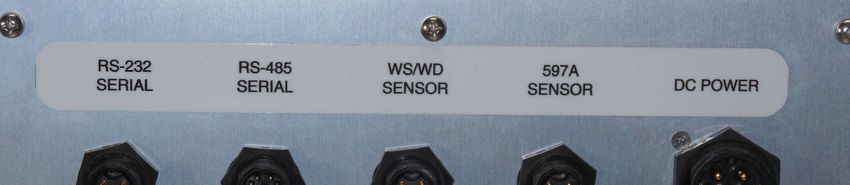
E-BAM-9805 Manual Rev E.docx Page 2
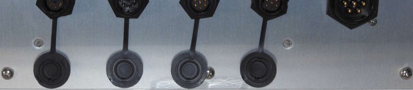
Table of Contents
1        INTRODUCTION                                                                                                                    6
1.1      About This Manual ........................................................................................................... 6
1.2      Technical Service ............................................................................................................. 6
1.3      E-BAM: Environmental Beta Attenuation Monitor............................................................. 6
1.4      Beta Radiation Safety Statement ..................................................................................... 7
1.5      E-BAM Specifications ....................................................................................................... 8

2        E-BAM INSTALLATION AND COMMISSIONING                                                                                               9
2.1      Unpacking ........................................................................................................................ 9
2.2      Accessories ...................................................................................................................... 9
2.3      Assembling the E-BAM .................................................................................................. 10
2.4      Electrical Connections .................................................................................................... 13
2.5      Power-up and Automatic Operation ............................................................................... 13
2.6      Power-up Settings Verification and Automatic Self-Test ................................................ 14
2.7      Configuring External Sensors......................................................................................... 16
2.7.1    Configuring the BX-597A Sensor ................................................................................... 16
2.7.2    Changing Sensor Addresses ......................................................................................... 16
2.8      Filter Tape Loading ........................................................................................................ 17
2.9      Warm-up Period ............................................................................................................. 17

3        E-BAM USER INTERFACE and MENU SYSTEM                                                                                                 18
3.1      The User Interface - Touchscreen Display Functions .................................................... 18
3.2      Main Operating Screen .................................................................................................. 18
3.3      Menu Hierarchy and Navigation ..................................................................................... 19
3.4      Operate Menu ................................................................................................................ 21
3.4.1    Start Sample .................................................................................................................. 21
3.4.2    Load Filter Tape ............................................................................................................. 21
3.4.3    Transfer Data ................................................................................................................. 21
3.4.4    About .............................................................................................................................. 22
3.4.5    Parameters..................................................................................................................... 22
3.4.6    Prepare Shipping ........................................................................................................... 22
3.4.7    Conc Chart ..................................................................................................................... 23
3.5      Test Menu ...................................................................................................................... 23
3.5.1    Leak Test ....................................................................................................................... 23
3.5.2    Ambient Temperature .................................................................................................... 24
3.5.3    Ambient Pressure........................................................................................................... 24
3.5.4    Flow Calibration ............................................................................................................. 24
3.5.5    Self-Test ......................................................................................................................... 24
3.5.6    Filter Sensors ................................................................................................................. 25
3.5.7    Span Mass Audit ............................................................................................................ 25
3.5.8    Tape Test ....................................................................................................................... 25
3.5.9    Inlet Heater..................................................................................................................... 25
3.5.10   Nozzle/Count Test.......................................................................................................... 26
3.5.11   Digital Link...................................................................................................................... 26
3.6      Setup Menu .................................................................................................................... 27

E-BAM-9805 Manual Rev E.docx                                                                                                   Page 3
3.6.1    Set Clock ........................................................................................................................ 27
3.6.2    Sample ........................................................................................................................... 27
3.6.3    Calibration ...................................................................................................................... 28
3.6.4    Tape Advance ................................................................................................................ 28
3.6.5    Restart BV ...................................................................................................................... 29
3.6.6    Clear Memory................................................................................................................. 29
3.6.7    Password ....................................................................................................................... 30
3.6.8    Report ............................................................................................................................ 30
3.6.9    Station ID ....................................................................................................................... 30
3.6.10   MET Average ................................................................................................................. 30
3.6.11   Serial Port ...................................................................................................................... 31
3.6.12   Modbus .......................................................................................................................... 32
3.6.13   Sound Volume................................................................................................................ 32
3.6.14   Touch Calibrate .............................................................................................................. 32
3.6.15   Language ....................................................................................................................... 32
3.7      Alarms ............................................................................................................................ 33

4        SAMPLE SITE SELECTION                                                                                                          34
4.1      Site Selection Requirements .......................................................................................... 34
4.2      Fall Hazard and Security Cautions ................................................................................. 34
4.3      Confined Sampling Locations......................................................................................... 34
4.4      Smoke and Ash Monitoring ............................................................................................ 35
4.5      Remote Monitoring with Solar or Battery Power............................................................. 35
4.5.1    External Battery Operation ............................................................................................. 35
4.5.2    Solar Operation .............................................................................................................. 36

5        MAINTENANCE, ALARMS and TROUBLESHOOTING                                                                                       37
5.1      Met One Suggested Periodic Maintenance .................................................................... 37
5.2      Basic Leak Check .......................................................................................................... 38
5.3      Advanced Leak Checks.................................................................................................. 40
5.3.1    Lower System Leak Test ................................................................................................ 40
5.3.2    Upper System Leak Test ................................................................................................ 41
5.3.3    Filter Tape Leak Test ..................................................................................................... 42
5.4      Background Determination (Mass Offset) ...................................................................... 43
5.5      Nozzle/Vane Cleaning .................................................................................................... 44
5.5.1    Nozzle/Vane Cleaning .................................................................................................... 44
5.5.2    Nozzle Interior Cleaning ................................................................................................. 46
5.6      Ambient Temperature Sensor Audit ............................................................................... 46
5.7      Ambient Barometric Pressure Sensor Audit ................................................................... 46
5.8      Flow Audits and Calibrations .......................................................................................... 47
5.9      Span Mass Audit ............................................................................................................ 50
5.10     Filter Sensors Audit ........................................................................................................ 52
5.10.1   Filter Temperature Sensor Audit .................................................................................... 52
5.10.2   Relative Humidity Sensor Audit ...................................................................................... 52
5.10.3   Upper and Lower Pressure Sensors Audit ..................................................................... 53
5.11     E-BAM Error Displays, Error Logs, and Error Codes...................................................... 54
5.12     E-BAM Hardware Failure Screen ................................................................................... 55
5.12.1   Sensor Out of Range Event ........................................................................................... 55

E-BAM-9805 Manual Rev E.docx                                                                                                   Page 4
5.13    Basic Problem and Cause/Solution Table ...................................................................... 56

6       DATA RETRIEVAL and COMMUNICATIONS                                                                                              58
6.1     Serial Input/output .......................................................................................................... 58
6.2     Transfer Data to USB Flash Drive .................................................................................. 59
6.3     Comet™ Data Retrieval Software .................................................................................. 59
6.4     Downloading Data Using HyperTerminal or other Terminal Programs........................... 61
6.4.1   User Communication ...................................................................................................... 61
6.4.2   Computer Communication.............................................................................................. 62

7       ACCESSORIES and PARTS                                                                                 63
7.1     Consumables, Replacement Parts, and Accessories ..................................................... 63

8       SPECIAL E-BAM CONFIGURATIONS                                                                                                      67
8.1     Comet Cloud Service Data Modem ................................................................................ 67
8.2     Wind Sensor Options ..................................................................................................... 67
8.2.1   EX2-034 ......................................................................................................................... 67
8.2.2   EX2-AIO ......................................................................................................................... 67

E-BAM-9805 Manual Rev E.docx                                                                                                Page 5
1 INTRODUCTION
1.1 About This Manual
This document is organized with the most important information toward the front of the manual,
such as site selection, installation, setups, and field calibrations, which all E-BAM owners and
operators should read and understand. Toward the back are sections that provide in-depth
information on subjects such as theory, diagnostics, accessories, and alternate settings. These
sections provide valuable information which should be consulted as needed. Electronic versions of
this manual are also available.

1.2 Technical Service
This manual is structured by customer feedback to provide the required information for setup,
operation, testing, maintaining, and troubleshooting of the E-BAM unit. Should support still be
required after consulting the printed documentation, contact one of the expert Met One Instruments,
Inc. technical service representatives during normal business hours of 7:00 a.m. to 4:00 p.m. Pacific
Standard Time, Monday through Friday. In addition, technical information and service bulletins are
often posted on the Met One Instruments, Inc. website. Please contact the service department and
obtain a Return Authorization (RA) number before sending any equipment back to the factory. This
allows for tracking and scheduling service work and to expedite customer service. Please have the
instrument serial number available when contacting the manufacturer.

   Contact         Tel: + 541 471 7111                Address: Met One Instruments, Inc.
   Information:    Fax: + 541 471 7116                         1600 Washington Blvd
                   Web: http:/www.metone.com                   Grants Pass, Oregon
                   Email: service@metone.com                   97526 U.S.A.

1.3 E-BAM: Environmental Beta Attenuation Monitor
The Met One Instruments, Inc. model E-BAM automatically measures and records airborne PM10 or
PM2.5 particulate concentration levels using the principle of beta ray attenuation. This method
provides a simple determination of concentration in units of milligrams of particulate per cubic meter
of air. A small 14C (Carbon 14) element emits a constant source of high-energy electrons known as
beta rays. Beta rays are detected and counted by a sensitive scintillation detector. A vacuum pump
pulls a measured amount of dust-laden air through the filter tape, which is positioned between the
source and the detector thereby causing an attenuation of the beta ray signal. The degree of
attenuation of the beta ray signal is used to determine the mass concentration of particulate matter
on the filter tape and the volumetric concentration of particulate matter in ambient air.
The E-BAM is designed as a simple, compact, and self-contained beta gauge, for portable
applications where rapid deployment and short interval real-time measurements are required. In
addition to the main housing, the monitor includes an internal pump, a multi-parameter ambient
sensor, and a mounting tripod. See section 2.2 for a listing of standard and optional accessories.

E-BAM-9805 Manual Rev E.docx                                                             Page 6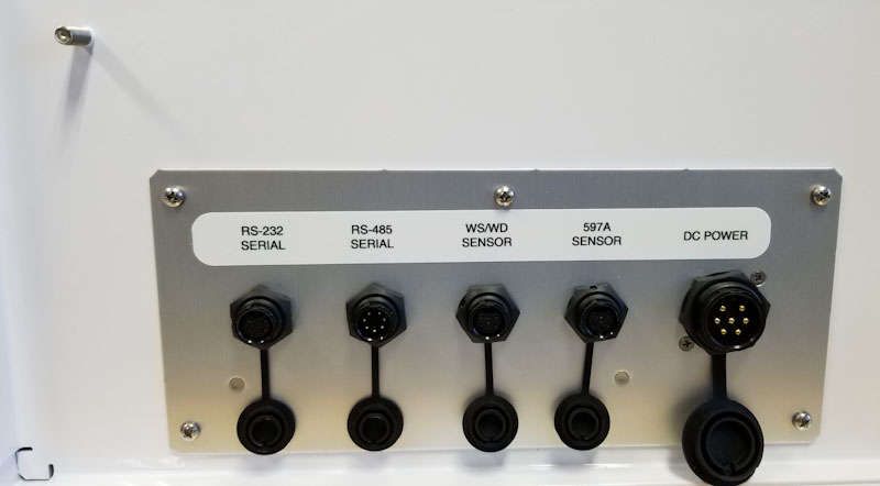
1.4 Beta Radiation Safety Statement
The Met One Instruments E-BAM contains a small 14C (Carbon 14) beta radiation-emitting source.
The nominal activity of the source is 60 microcuries, which is below the “Exempt Concentration
Limit” as defined in 10 CFR Section 30.71 – Schedule B. The owner of an E-BAM is not required to
obtain any license in the United States to own or operate the unit. The owner of an E-BAM may
elect to return the entire unit to Met One Instruments for recycling of the 14C source when the unit
has reached the end of its service life, although the owner is under no obligation to do so. Under no
circumstances should anyone but factory technicians attempt to remove or access the beta source.
The beta source has a half-life of about 5730 years and should never need to be replaced unless it
becomes damaged or corroded. Neither the 14C source nor the beta particle detector are
serviceable in the field. Should these components require repair or replacement, the E-BAM must
be returned to the factory for service and recalibration. The E-BAM is manufactured in compliance
with the U.S. NRC safety criteria in 10 CFR 32.27.

E-BAM-9805 Manual Rev E.docx                                                             Page 7
1.5 E-BAM Specifications
PARAMETER SPECIFICATION*
Measurement Principle Particulate Concentration by Beta Attenuation
U.S. EPA Designations None
Measurement Range -15 g/m3 – 10,000 g/m3
Measurement Resolution 1.0 g/m3
Sensitivity Standard Deviation (σ) (1 hour) Less than 3.0 g/m3
Lower Detection Limit† (2σ) (1 hour) Less than 6 g/m3
(2σ) (24 hour) Less than 1.2 g/m3
Measurement Sample Time 1 Hour
Flow Rate 16.7 L/min inlet flow rate; actual volumetric flow
Filter Tape Continuous glass fiber filter; 30 mm x 21 m roll; > 60 days/roll
Span Check Manual, 800ug (typical), span foil included.
Beta Source C-14 (carbon-14); 60 µCi ±15 µCi (< 2.22 X 10⁶ Beq); Half-Life 5730 years
Beta Detector Type Photomultiplier tube with organic plastic scintillator
Operating Temperature Range -25° to +50°C.
Operating Humidity Range 0 – 90% RH, noncondensing
Inlet Humidity Control Actively controlled inlet heater module
User Interface 4.3” graphical touch screen
Ambient Sensor Model BX-597A combination AT, RH, and BP serial sensor AT: -50° to +70°C;
RH: 0 to 98%; BP: 375 to 825 mmHg
7500 Digital Serial Interface 2 channels, half duplex RS-485
Serial Interface 1 channel; full duplex RS-232, USB (Shared common serial output)
1 channel; half duplex RS-485
Baud rates: 2400, 4800, 9600, 19200, 38400, 57600, 115200
Internal Data Storage 15 Days 1-minute average, 2.6 years 60-minute average
External Data Storage 1 USB Flash drive device
Compatible Software Air Plus 5, Comet™, HyperTerminal®
Power Supply Universal 100-230 VAC input, 12 VDC output power supply included. Compatible
with solar power kits or external batteries using included External Battery Cable.
Power Consumption 2.65 amps @12VDC (32 Watts) - Normal sampling with inlet heater off.
3.65 amps (44 Watts) - Normal sampling with maximum inlet heat.
5.5 amps (66 Watts) - Maximum pump speed with maximum inlet heat.
Weight 31 lbs. (14.1 kg)
Dimensions (Without Tripod) Height: 18 in (46 cm) Width: 16 in (41 cm) Depth: 9 in (23 cm)
* Specifications may be subject to change without notice.
† The hourly detection limit is defined as twice the standard deviation of the hourly zero noise of the instrument. The
24-hour detection limit is defined as the hourly detection limit divided by the square root of 24 (approximately 4.9).
E-BAM-9805 Manual Rev E.docx Page 8
2 E-BAM INSTALLATION AND COMMISSIONING
This section describes assembly, start-up, and filter tape installation for the E-BAM unit.
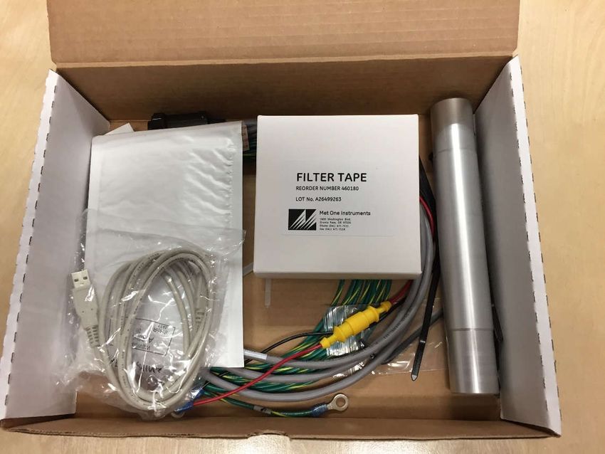
2.1 Unpacking
Any damage incurred to the equipment during shipping are the responsibility of the carrier. If any
damage to the shipment is noticed before unpacking, a claim must be filed with the commercial
carrier immediately. Follow any special unpacking instructions provided by the carrier as all items
are then carefully removed from the containers. Inspect each component thoroughly. It is
recommended to document and photograph all damaged packages and items before, during, and
after unpacking them. Contact Met One Instruments, Inc. (see section 1.2 of this manual) to arrange
for any replacement items needed.
Unpack the mass monitor and accessories and compare them to the packing list to make sure all
items are present.
The E-BAM is shipped with the nozzle shipping device installed under the nozzle which prevents
the vane assembly from being damaged in transit. The device must be replaced anytime the mass
monitor is being transported in order to avoid damaging the nozzle and vane assembly. Do not ship
or transport the E-BAM with filter tape installed.
Please keep all special shipping items (box, foam packing material, etc.) used to ship the E-BAM.
They should be re-used if the monitor is transported (changing site locations, returning to the
factory, etc.). Met One Instruments, Inc. is not responsible for damage to the mass monitor if
shipped in non-original packaging or without the shipping shim in place. Contact Met One
Instruments, Inc. (see section 1.2 of this manual) for replacement packing materials, if necessary.
2.2 Accessories
Every E-BAM requires the use of ancillary components. The items supplied with a standard E-BAM
PM10 monitoring system are shown in Table 2-1.
Standard Components Part No.
Mounting Tripod EX-905
PM10 Size Selective Inlet BX-802
Inlet Tube (8.5 inches) 9187
Ambient Combination Sensor (AT, BP, RH) BX-597A w/ 82959-8 Cable Assembly
Filter Tape 460180
Accessory Kit* 83293
*See section 7 for a complete listing of all items contained in the Accessory Kit
Table 2-1 Standard E-BAM Accessories
E-BAM-9805 Manual Rev E.docx Page 9
Application and installation dependent accessories for the E-BAM are also available from Met One
Instruments, Inc. Common optional items are shown in Table 2-2.
Common Optional Component Part No.
Wind Speed and Direction Sensor EX2-034 or EX2-AIO
PM2.5 Sharp Cut Cyclone BX-807
Volumetric Flow Calibration Kit BX-307
Zero Filter Kit BX-302
Table 2-2 Optional E-BAM Accessories
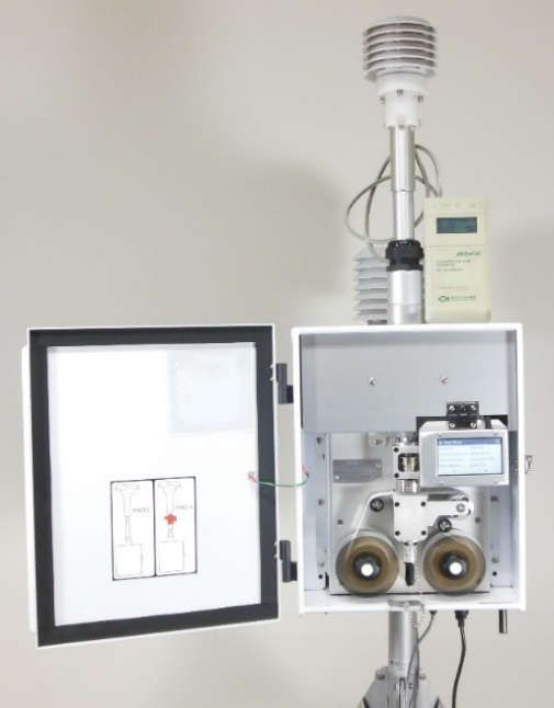
2.3 Assembling the E-BAM
The E-BAM is designed to be field deployable by an average person in less than 15 minutes under
normal conditions. Refer to the photos and diagrams below while performing the following steps to
assemble the unit:
1. Deploy the tripod: Remove the three stainless steel detent pins from the tripod base by
pulling the rings. Unfold the three tripod legs and reinsert the three pins so that each pin
secures a leg in the open position. Make sure the erected tripod is rigid and stable. Fasten or
bolt down the tripod legs to prevent tip over (see section 4.2Error! Reference source not
found.)
Detent Pins
Figure 2-1 Tripod Deployment
2. Install the E-BAM onto the tripod: Lift the E-BAM assembly and slide the slot on the back
of the E-BAM over the tab on the top of the tripod. Insert the supplied ¼- 20 bolt through the
tab on the bottom of the E-BAM and through the hole in the body of the tripod (see Figure
2-2). Secure it with the supplied washers and nut. This prevents the E-BAM from shifting on
the tripod.
3. Install the inlet components: Loosen the weatherproof fitting on top of the E-BAM and
insert the short inlet tube into the top of the unit. The tube must go through the fitting and
through two O-rings in the top of the E-BAM. Make sure the tube is fully seated by rotating it
back and forth. Tighten the weatherproof fitting to secure the inlet tube. For PM10 monitoring,
install the BX-802 PM10 inlet directly onto the top of the short inlet tube. If a BX- 807 cyclone
is to be used for PM2.5 monitoring, it must be installed under the PM10 head as shown in
Figure 2-2. Lubricate the O-rings as necessary.
E-BAM-9805 Manual Rev E.docx Page 10Figure 2-2 Tripod Mounting of the E-BAM
4. Install BX-597A Sensor: Connect the BX-597A sensor to the post on the back of the tripod
with the supplied mounting hardware (user supplied 7/16” wrench required). The BX-597A
sensor should face away from the E-BAM as shown in Figure 2-3. Verify configuration after
power- up as detailed in section 2.7.1.
Figure 2-3 Mounting the BX-597A Sensor
E-BAM-9805 Manual Rev E.docx Page 115. Optional Wind Sensor: If an optional wind speed/direction sensor (such as the EX2-034 or
EX2-AIO) is purchased a cross-arm tube to use for mounting the wind sensor will be
included. Connect the cross-arm to the post on the back of the tripod with the supplied ¾” x
¾” fitting and set screws and then install the sensor at end of the arm as suggested in Figure
2-4. The wind sensor should be as far from the E-BAM unit as possible, and the wind vane
must be able to rotate fully without obstruction. Plug the wind sensor into the corresponding
connector on the bottom of the E-BAM. Depending on the type of wind sensor, it may need to
be oriented to the south. Consult the separate manual that comes with the wind sensor for
details. Verify configuration after power-up as detailed in section 2.7.2.
Figure 2-4 Sensor Mounting with an Optional Wind Sensor
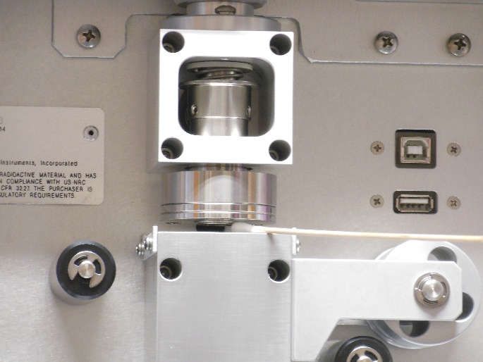
E-BAM-9805 Manual Rev E.docx Page 122.4 Electrical Connections
The E-BAM has a set of weatherproof connectors on the bottom of the unit. These connectors
provide the connections for the power supply, external sensors, and communications.
The E-BAM chassis ground lug should be connected to an earth ground whenever possible, to
reduce electrical noise in the unit. A 20-foot ground cable is included in the Accessory Kit.
Chassis Ground Stud
Figure 2-5 E-BAM Connectors
2.5 Power-up and Automatic Operation
The E-BAM is designed to turn on automatically when power is applied. It will provide options to
start immediately or enter the setup menus. If START NOW is selected, ensure shipping device is
removed. Choosing setup will present several setup menus for verification. These are described in
section 2.6.
Note: If no user activity is detected for several minutes after power-up, the E-BAM will automatically
begin sampling based on the existing setup options and settings, if filter tape is installed, and no
hardware or voltage failures are detected. This makes it possible to fully configure and calibrate the
unit in the lab, then simply deploy it to the field and power it up with no further actions required.
Always remove the shipping device before allowing the monitor to self-start.
E-BAM-9805 Manual Rev E.docx Page 132.6 Power-up Settings Verification and Automatic Self-Test
The E-BAM will present several setup parameters for verification whenever it is powered on. These
setup screens can also be viewed or edited in the SETUP menu under the main E-BAM menu
system. See section 3.6 for detailed descriptions of the SETUP parameters.
When power is applied to the E-BAM, the unit will show the startup splash screen for the
touchscreen display for a moment, then display the welcome screen as shown in Figure 2-6.
Figure 2-6 Welcome Screen
Press the SETUP button and the clock screen is displayed (see Figure 2-7). If the time and date are
correct, press the YES button again. If the date or time need to be changed, press the EDIT button.
See section 3.6.1 for details on changing the date and time.
Figure 2-7 Verifying the Clock
After the time is verified, the unit will display the Settings screen shown in Figure 2-8 below. If the
settings need to be changed, press the green bordered value box to be updated and the associated
edit screen will be displayed.
Figure 2-8 Verifying the Initial Settings
After confirming or setting the Station ID (Section 3.6.9) and MET Average (Section 3.6.10) settings,
press OK.
The E-BAM will then check whether a roll of filter tape is installed. If no tape is detected, the unit will
prompt for installation of filter tape:
E-BAM-9805 Manual Rev E.docx Page 14Figure 2-9 Verifying Filter Tape is loaded
Install a roll of filter tape as described in section 2.8. When the filter tape is installed, press MOVE.
The unit will again try to detect the tape.
If tape is detected, the unit will proceed to the self-test screen. Press START to begin a self-test.
After a successful self-test, press the X to proceed to operations.
Figure 2-10 Self-Test Screen
E-BAM-9805 Manual Rev E.docx Page 152.7 Configuring External Sensors The E-BAM must have a BX-597A sensor connected and properly configured for operation. If the BX-597A is not present, the E-BAM will not begin sampling. See section 8.1 for more details about available wind sensors. 2.7.1 Configuring the BX-597A Sensor The E-BAM requires a BX-597A sensor at address 1 of its serial network to begin sampling. Once the physical connections are made the sensor is programmed using the Digital Link screen located in the Test menu (see section 3.5.11). Upon entering the Digital Link screen, any digital sensor connected to the E-BAM with address 1 or 2 programmed in it will appear in either the Sensor 1 or Sensor 2 fields, as appropriate. In addition to the sensor type, the address fields on this screen also display the firmware currently installed in the sensor. Figure 2-11 shows a typical configuration. Figure 2-11 The Digital Link Screen The State field indicates that the E-BAM is either starting up digital communications or waiting for a response from the sensor. If either the sensor type or firmware revision is missing or incorrect, communications are not properly established with the sensor. The grey SETUP button in the lower left corner provides access to the Digital Setup screen for configuring the addresses of the digital sensors. See section 2.7.2 for details. 2.7.2 Changing Sensor Addresses The default address for most Met One Instruments, Inc. digital sensors is 1. If a connected sensor has an address other than 1 or 2, it can be located in the Digital Setup screen by pressing the grey SCAN button in the bottom left corner (see Figure 2-12). The E-BAM will scan through all potential network address nodes to locate any connected devices. Progress of this scan can be seen in the third address field label (which displays Addr 3, by default) and the word “Scanning” will appear in the field itself. Figure 2-12 Scanning for Sensors If a device is located at some other address, it can be changed by pressing the grey CHANGE button next to the third address field. In the example shown in Figure 2-13, the BX-597A has been configured for address 2. Pressing the grey SET 1 button will update the address in the sensor to address number 1 and exit back to the main Digital Link screen. The Sensor 1 field will now display the BX-597A details like Figure 2-11. Figure 2-13 Change the Address If two sensors share the same address, disconnect one of them and then use the CHANGE button to set the other one to a different address. Remember that the BX-597A must be configured for address number 1 and if an optional wind sensor is connected, it will need to be set to number 2. E-BAM-9805 Manual Rev E.docx Page 16
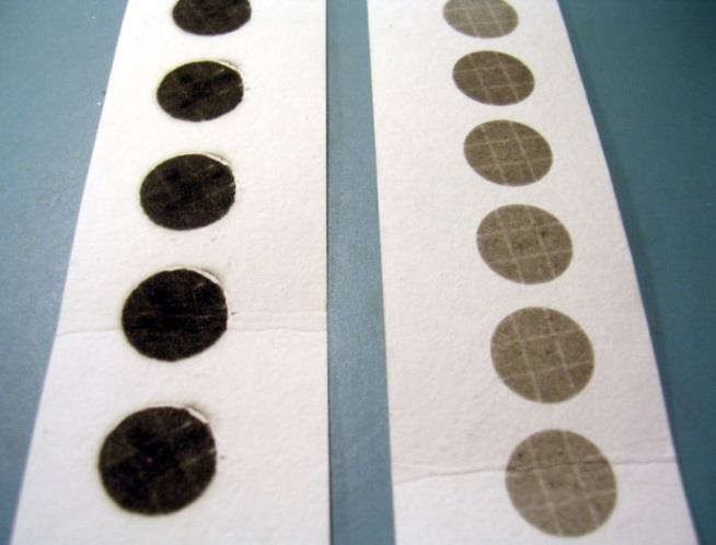
2.8 Filter Tape Loading
Filter tape must be loaded into the E-BAM for sampling. One roll of tape will last anywhere from a
few weeks to more than a year, depending on the Tape Advance setting (see section 3.6.4) and
ambient particulate levels. It is important to have spare rolls of tape available to avoid data
interruptions. Used filter tape should never be “flipped over” or re-used. This will result in inaccurate
measurements! When loading a roll of filter tape, use the following steps:
   1. If the nozzle is in the down position, it will need to be raised. Enter the Load Filter Tape
      screen in the Operate menu. The unit will raise the nozzle and provide a prompt to load the
      filter tape.
   2. If replacing a used roll of tape, remove the old roll and then thoroughly clean the nozzle and
      vane as described in section 5.5.
   3. An empty core tube must be installed on the left (take-up) reel hub. This provides a surface
      for the used tape to spool-up on. Met One supplies a plastic core tube to use with the first roll
      of tape. After that, use the empty cardboard core tube left over from the last roll to spool-up
      the new roll. Never fasten the filter tape directly to the aluminum hub!
   4. Load the new roll of filter tape onto the right (supply) reel and route the tape through the
      nozzle area as shown in Figure 2-14. Attach the loose end of the filter tape to the empty core
      tube with tape.
   5. Rotate the tape roll to remove excess slack, then install the plastic spool covers tightly. The
      spool covers clamp the tape rolls to the hubs to prevent them from slipping.
   6. Press the grey MOVE button to verify tape is properly loaded.
   7. Press the X button to return to the Operate menu.

                               Figure 2-14 Proper Loading of the Filter Tape

2.9 Warm-up Period
The E-BAM must warm up for at least one hour before optimum accuracy of the concentration data
can be obtained. This is because the beta detector contains a vacuum tube which must stabilize.
This applies any time the unit is powered up after being off for more than a moment. Setups, tests,
and flow calibrations can be performed during this warm up time. The first hour of data should often
be discarded or ignored.

E-BAM-9805 Manual Rev E.docx                                                               Page 17
3 E-BAM USER INTERFACE and MENU SYSTEM
This section describes the E-BAM user interface system. It also explains the functions of the main
and sub menu options, navigation of the menus, and how to view data and errors.
3.1 The User Interface - Touchscreen Display Functions
The E-BAM user interface is a touchscreen display used to control almost all the features and
functionality of the E-BAM. It is mounted inside the enclosure on a hinged stainless-steel plate
located on the right-hand center of the monitor.
3.2 Main Operating Screen
In addition to the last hourly concentration reading, this screen shows the current real-time values
being measured and the operational state of the E-BAM.
Figure 3-1 The E-BAM Main Operating Screens
Note that the display has a limited amount of space and cannot show all the real time data on one
screen. Tap down arrow key in the lower left corner of the display to navigate between the three
screens shown in Figure 3-1.
Note: A concentration value of 99.999 mg/m3 or 99999 ug/m3 is an invalid concentration
measurement and is due to an appropriate alarm condition. It will also be displayed when initially
starting the instrument until completion of the monitor’s first successful measurement sample.
Table 3-1 describes the parameters visible in the main sampling display as shown in Figure 3-1. In
addition to the hourly, standard, and real-time average concentrations, the logged parameters in the
E-BAM are:
Parameter Description
Conc HR The concentration at Actual conditions of the last hourly sample
Status The current operational status or alarm condition of the monitor
ConcS The concentration (at Standard conditions) of the last hourly sample
Conc RT The average real-time period concentration (see Section 3.6.2)
FLOW Primary air flow rate in actual LPM
AT BX-597A Ambient Temperature
RH BX-597A ambient Relative Humidity
BP BX-597A ambient Barometric Pressure
FT Internal Filter Temperature after the filter tape in degrees C
FRH Internal Filter RH after the filter tape
WS Wind speed in meters per second (if equipped)
WD Wind direction in degrees (if equipped)
Table 3-1 Main Display Parameter Descriptions
E-BAM-9805 Manual Rev E.docx Page 183.3 Menu Hierarchy and Navigation
The E-BAM menu structure is outlined in the following table.
Main Menu Sub Menu Options Overview
Operate Start Sample Begin or resume monitoring.
See section 3.4 Load Filter Tape Transfer Load and properly tension the filter tape
Data Download stored data to a USB memory stick
About Details the current E-BAM firmware type and version number
Parameters Review current settings
Prepare Shipping Prepares for shipping unit
Conc Chart A real-time chart of conc
Test Leak Test Perform the leak test
See section 3.5 Ambient Temperature Calibrate ambient temperature or restore default settings
Ambient Pressure Calibrate ambient pressure or restore default settings
Flow Calibration Calibrate flow rate or restore default settings
Run Self-Test Run the E-BAM Self-Test
Filter Sensors Calibrate filter temp, pressure, and RH or restore default settings
Span Mass Audit Run the zero and span foil tests
Tape Test Verify tape travels expected distance
Inlet Heater Manually turn the inlet heater on and off
Nozzle/Count Test Beta-Count Test
Digital Link Test and configure communications with digital sensors
Setup Clock Set the date and time
See section 3.6 Sample Set the conc. units and the averaging interval for collecting real time data
Calibration Change the concentration offset & span membrane
Inlet Heater Set the RH threshold for the inlet heater to activate
Tape Advance Set the differential pressure threshold for advancing the filter tape
Restart BV Set the battery voltage threshold for resumption of sampling operations
following a Low Battery alarm
Clear memory Clear all stored data
Password Change the master password
Reports Set the type of time stamp to use for the hourly report
Station ID Set the location number used to identify the E-BAM
MET Average Set the averaging interval for collecting other than hourly data
Serial Port Set the baud rate and connection type for serial communications
Modbus Set the Modbus port and address
Sound Volume Touch Adjust the volume of the touchscreen sounds
Calibrate Calibrate the touch screen
Language Set the language
Alarms No sub menu View alarms
See section 3.7
Table 3-2 Menu Hierarchy
Menu selections and instructions are detailed in the following sections of this operating manual as
detailed in the Main Menu column Table 3-2 above.
E-BAM-9805 Manual Rev E.docx Page 19To access the various main menus, press the
three horizontal lines in the top left corner. A
drop-down menu will appear (Figure 3-2) to
allow selection of any of the four main menus.
This option is available on all main menu
screens (such as the Setup Menu shown in
Figure 3-3) and on the main operating screen
Figure 3-2 Main Menu Drop Down Selections
To return to the main operating screen (see
section 3.2), press the Home icon located in
the upper right corner of all main menu
screens. This icon can clearly be seen in the
Setup Menu image shown here in Figure 3-3
Figure 3-3 Setup Menu
To cancel and action and return to the
previous menu screen, press the X icon
located in the upper right corner of all sub
menu screens. This icon can clearly be seen
in the Set Clock screen image in Figure 3-4.
Figure 3-4 Set Clock Screen
Some parameters, such as the Date and Time
settings (Figure 3-4) or a Location value,
require numeric entry. When pressing the
button to edit such a field, a visual keypad
(Figure 3-5) will open and allow operators to
input the value. Press the OK key to accept
the changes or the Cancel key to return to the
previous screen. The X key on the far right
Figure 3-5 Keypad for Numeric Entry
performs a backspace operation
E-BAM-9805 Manual Rev E.docx Page 203.4 Operate Menu
The Operate Menu is the doorway to the most commonly used areas for normal operation of the E-
BAM.
Figure 3-6 The Operate Menu
3.4.1 Start Sample
This screen allows users to both start and stop
the E-BAM sampling process. Upon entering this
screen, a warning will be displayed asking users
if they would like to start or stop a sample,
depending on the current state of the monitor. If
there is no sample currently being taken, the
grey button in the lower left corner will be labeled
START. If there is a sample in progress, it will
Figure 3-7 The Start Sample Screen
read STOP.
3.4.2 Load Filter Tape
This menu option is used for filter tape
installation. Load the tape and press the MOVE
key to go back to the main menu. See section
2.8 for details.
Figure 3-8 The Load Filter Tape Screen
3.4.3 Transfer Data
Copying data to a USB memory stick is performed from this screen. See section 6.2 for detailed
instructions.
E-BAM-9805 Manual Rev E.docx Page 213.4.4 About
This screen shows the monitor’s serial number
and installed firmware type and version number.
It also provides firmware type and version
number for the touchscreen display.
Figure 3-9 The About Screen
3.4.5 Parameters
These screens are not password protected. They provide the ability to view the real time value of a
wide variety of parameters. Results are updated once per second. No changes can be made in
these screens. They are for viewing purposes only.
Figure 3-10 Parameters
Note that the display has a limited amount of space and cannot show all the real time data on one
screen. Tap the down arrow key in the lower left corner of the display to scroll through the four
screens shown in Figure 3-10. Tapping the arrow on the last screen will return to the first one
3.4.6 Prepare Shipping
This screen provides a means of inserting the shipping shim and securing it in place for transporting
the instrument. To use it, simply press the Prepare Shipping field on the main Operate Menu. The
nozzle will raise and instruct users to insert the shipping device (see Figure 3-11). Once inserted,
the nozzle will automatically lower and lock the shipping device in place. At this point, the display
will change to indicate that the E-BAM may be shut down. Remove power from the monitor and it is
now ready to be disassembled and relocated.
Figure 3-11 Prepare Shipping
E-BAM-9805 Manual Rev E.docx Page 223.4.7 Conc Chart
This screen provides a chart of the last 24 hourly (Conc HR) concentration measurements.
3.5 Test Menu
The Test Menu provides a means of testing and calibrating individual sensor inputs and
calculations. Because these settings directly impact flow and concentration values, most of these
tests are password protected.
Figure 3-12 Test Menus
3.5.1 Leak Test
This screen provides the options and indications
needed to perform a leak test of the sampling
system. The grey pump control button in the
lower left corner will read PUMP ON which
indicates that pressing it will turn on the pump.
Similarly, when the pump is running, this button
will display PUMP OFF. Figure 3-13 The Leak Test Screen
The grey NOZZLE control button in the lower right corner will always be labeled as NOZZLE when
this test screen is first entered. Pressing it will cause the button label to change NOZZLE UP or
NOZZLE DOWN. The button will now display what will happen if it is pressed again, just like the
pump control button. This means that it will read NOZZLE UP if the nozzle is in the down position
or NOZZLE DOWN if it is in the up position.
The flow and lower pressure sensor indications are provided for reference when performing the leak
test. See section 5.2 for detailed instructions on performing a leak test.
E-BAM-9805 Manual Rev E.docx Page 233.5.2 Ambient Temperature
This screen provides the options and
indications needed to default, verify, and
calibrate the external ambient temperature
sensor as part of the flow audit and
calibration. See section 5.6 for detailed
instructions.
Figure 3-14 The Ambient Temperature Screen
3.5.3 Ambient Pressure
This screen provides the options and
indications needed to default, verify, and
calibrate the external ambient pressure
sensor as part of the flow audit and
calibration. See section 5.7 for detailed
instructions.
Figure 3-15 The Ambient Pressure Screen
3.5.4 Flow Calibration
These four screens provide the options and
indications needed to default, verify, and
calibrate the internal flow sensor as part of
the flow audit and calibration procedures.
See section 5.8 for detailed instructions.
Figure 3-16 Flow Calibration Screen (1 of 4)
3.5.5 Self-Test
This screen runs the self-test sequence. Press X to exit once it is complete
Figure 3-17 The Self Test Screen
E-BAM-9805 Manual Rev E.docx Page 243.5.6 Filter Sensors This screen provides the options and indications needed to default, verify, and calibrate the filter temperature, humidity, and upper and lower pressure sensors. See section 5.10 for detailed instructions. The Filter Sensor field indicates which sensor is currently being audited. To select a different sensor, press the green bordered value box and a list of the sensors will be displayed. Use the arrow buttons at the bottom of the screen to see more choices. Tap the option to be used, and it will be selected. Press the OK button to exit the screen and audit the sensor. Figure 3-18 The Filter Sensors Screen The E-BAM field displays the current value of the chosen Filter Sensor. The Standard field is the field where the value shown on the traceable reference standard is entered if the E-BAM value needs to be adjusted. To make a change, press the green bordered value box and the numerical entry keypad (Figure 3-5) will be displayed. Enter the value currently shown on the standard and press the OK key to set it. Press the CALIBRATE key to set any changes. The E-BAM and Standard fields should now match. The DEFAULT key can replace the current calibration factors with the factory default settings on any of the four sensors. If difficulty is encountered during the audit process, press the DEFAULT key to set that specific sensor back to factory values and then try the calibration again. 3.5.7 Span Mass Audit This screen runs the Span Mass Audit. The sequence begins as soon the menu is entered. See section 5.9 for detailed instructions. 3.5.8 Tape Test This screen provides a means to verify proper installation and operation of the filter tape and motors. Press the grey TEST TAPE button to advance the tape. The pass criteria is ≥ 12 mm. The status of the tape, such as OK or if there is a Tape Break error, will be displayed to the right of the TEST TAPE button. Figure 3-19 The Tape Test Screen 3.5.9 Inlet Heater This screen allows manual operation of the inlet heater assembly. Press ON to turn the heater on and verify the element heats up as expected. Press OFF to turn the heater off; verify it shuts off and then cools down. Exiting this test screen will also turn off the heater if it is left in the ON state. Figure 3-20 The Inlet Heater Test Screen E-BAM-9805 Manual Rev E.docx Page 25
3.5.10 Nozzle/Count Test
The Nozzle/Count Test screen provides the ability
to manually raise and lower the nozzle. Pressing
the grey NOZZLE button will cause the nozzle to
change state. When the nozzle is in the down
position, the E-BAM beta count results can also
be verified as shown in Figure 3-21. The
frequency for beta counts is typically greater than
1500 Hz.                                                Figure 3-21 The Nozzle/Count Test Screen

Counting should only occur when the nozzle is in the down position. Figure 3-21 shows a typical
count value for the Beta Count field.
The 1-Minute Count test is for troubleshooting purposes with factory support technicians and will not
commonly be used when deployed. Pressing the grey START button will begin the 1-Minute Count
test. The counts displayed in the 1-Minute Count Field will start from zero and begin counting up. A
60 second countdown timer will be shown in parenthesis next to the count value.
3.5.11 Digital Link

Test digital communications with the BX-597A by
entering this screen. The BX-597A firmware
version should be displayed when the proper link
is established. See section 2.7 for details on
how to configure the BX-597A sensor, as well as
any optional wind sensors.
                                                           Figure 3-22 The Digital Link Screen

E-BAM-9805 Manual Rev E.docx                                                             Page 26
3.6 Setup Menu
The Setup Menu grants access to the configuration of most of the operating parameters for the E-
BAM. It allows for changing the offsets, clearing the memory, setting the date and time, and much
more. Because of the changes able to be made, the Setup Menu is password protected.
Figure 3-23 Setup Menus
Note that the display has a limited amount of space and cannot show all options on one screen. Tap
the down or up keys in the lower right corner of the display to navigate between the three screens
shown in Figure 3-23.
3.6.1 Set Clock
This is where the date and time are set. Press the
green box of the field that needs to be modified.
The numerical entry keypad (Figure 3-5) will be
displayed and allow entry of the value for that
parameter. Once all fields have been entered,
press the grey Set button in the lower left corner
to set them. Figure 3-24 The Set Clock Screen
3.6.2 Sample
The concentration (Conc) Units of the E-BAM can
be set to either mg/m3 or μg/m3. To change this
setting, press the green bordered value box and a
list of the settings available will be displayed.
Select the desired units and the press the grey
OK button.
Figure 3-25 The Sample Screen
The Real Time Period sets the time interval for the real-time concentration (Conc RT) algorithm.
The Conc RT will use the last X number of minutes where X is Real Time Period value set in the
Sample menu screen.
For example, if 15 minutes is chosen, nothing will be displayed for minutes 1-14. After minute 15,
the first Conc RT will be displayed. Each minute after that will update the Conc RT based on the
previous 15 minutes. This means that minute 16 will display the data from minute 2-16, and so on.
The Real Time Period may be set anywhere from 8 to 60 minutes, in one-minute increments.
E-BAM-9805 Manual Rev E.docx Page 273.6.3 Calibration The background value is the zero correction (offset) for the E-BAM concentrations. It is applied to all data collected to compensate for measured mass in the absence of any particulate matter. This screen allows for editing the background zero correction factor after performing a zero test with the BX-302 Zero Filter. See section 5.4. Figure 3-26 The Calibration Screen Press the green bordered value box and the numerical entry keypad (Figure 3-5) will be displayed. Enter the new calculated correction factor. Regardless of the concentration units setting the background is always entered in units of mg/m3. Met One supplies the E-BAM with a factory-set background value. Use the BX-302 zero filter kit to audit the background value and set it for local conditions. See the BX-302-9800 manual for the zero-test procedure or contact the Met One Instruments service department (see section 1.2) for more information. WARNING: This calibration value may significantly affect the accuracy of the unit. The grey ADVANCED button in the lower left corner provides access to the K factor setting for the E-BAM. This should NOT be adjusted unless directed by factory personnel. It is set at the factory and altering it will void the unit’s calibration. 3.6.4 Tape Advance The filter tape in the E-BAM will be automatically advanced at a specified time interval or whenever too much particulate has been deposited on it. The tape advance time is adjustable and can be set to Auto, 1, 2, 3, 4, 6, 8, 12, or 24 hours. It is recommended to use the greatest duration possible while avoiding an automatic advance due to a pressure drop error. This will allow for maximum tape usage over time. The shorter the advancement period is set, the faster the filter tape will be consumed. The “Auto” setting will result in a Figure 3-27 The Tape Advance Screen tape advance only when tape pressure has been exceeded. Heavy particulate buildup will result in an excessive pressure drop across the tape. If the pressure drop gets too large, the E-BAM will advance the filter tape to a clean spot and then continue sampling. This is to prevent straining the pump when sampling in air with higher contamination levels. The pressure threshold for this action can be set from 50 to 350 mmHg in one mmHg increments. To change the Tape Period, press the green bordered value box and a list of the settings available will be displayed. Tap the required option and it will be applied. To change the Tape Pressure, press the green bordered value box and the numerical entry keypad (Figure 3-5) will be displayed. Enter the new pressure threshold value and press the OK key to set it. Decimal values will be rounded up or down to the nearest whole number. E-BAM-9805 Manual Rev E.docx Page 28
3.6.5 Restart BV
The Battery Voltage level (BV) displayed in the Parameters screen (Figure 3-10) represents the DC
input voltage as measured by the device. The reported BV level is always less than the supplied
input voltage due to a voltage drop caused by internal circuit protection components. For example,
connecting a typical fully charged battery with a voltage of approximately 12.7V will result in an E-
BAM BV level of approximately 12.2V. The Restart BV setting is an important parameter to
understand if the unit is to be run on batteries or solar power. If the BV level drops to a 1-minute
average of 11.0 volts, the E-BAM will generate a Low Battery alarm and stop sampling, entering
standby mode. The Restart BV setting is the lowest BV level at which the E-BAM will resume
sampling, such as after the battery has been recharged. This allows the batteries enough time to
adequately recharge before the E-BAM turns back on, particularly when used with a solar panel
array, and prevents the unit from rapidly cycling on and off when the batteries are low. The default
setting of 12.5V is suitable for most solar panel array configurations. Consult your battery
documentation for the optimal recharge profile. The Restart BV threshold can be set from 11.0 to
15.0V. Press the green bordered value box and the numerical entry keypad (Figure 3-5) will be
displayed. Enter the new Restart BV level and press the OK button to set it.

                                   Figure 3-28 The Restart BV Screen
3.6.6 Clear Memory
The alarm and data logs may be cleared from this screen by pressing either the CLEAR DATA or
CLEAR ALARM button. A warning screen will appear and request confirmation that all data will be
cleared. Press the CLEAR to erase the data (or alarm) log or press the white X in the upper right
corner of the screen to cancel the operation without erasing the log.

                                 Figure 3-29 The Clear Memory Screen

E-BAM-9805 Manual Rev E.docx                                                            Page 29
3.6.7 Password
Certain menus and options of the E-BAM are
password protected. A valid password consists of
any four digits, and this is the screen that provides
access to change it. Press the green bordered
value box and the numerical entry keypad (Figure
3-5) will be displayed. Enter the new password.
Setting the Password to 0 removes password
protection on all user accessible menus and Figure 3-30 The Password Screen
options.
3.6.8 Report
The report time stamp can be set to mark the data
with the time from either the beginning or ending
of the hour. For example, if set to BEGINNING,
data collected during the hour from 8:00 to 9:00
would be marked as 8:00. Similarly, if that data
were collected with ENDING as the choice, the
data time stamp would be 9:00 instead.
Figure 3-31 The Report Screen
3.6.9 Station ID
This screen provides the option to enter a three-
digit location ID for the E-BAM. Press the green
bordered value box and the numerical entry
keypad (Figure 3-5) will be displayed. Enter the
new location ID value.
Figure 3-32 The Station ID Screen
3.6.10 MET Average
The default averaging period for the E-BAM is 60 minutes. If an alternate averaging period is
needed, it may be selected from this screen. Press the green bordered value box and the selection
screen shown on the right of Figure 3-33 will be displayed. Not all choices are able to be presented
at the same time. Use the up and down arrow keys under the displayed options to show additional
selections Tap the required period length and then press the OK button to set it. The available MET
average periods are 1, 5, 10, 15, 30, and 60 minutes.
Figure 3-33 The MET Average Screens
E-BAM-9805 Manual Rev E.docx Page 303.6.10.1 Data Average Capacity
The E-BAM internal data logger can store 22,528 records. With a fixed number of records, the time
until the internal logger is full will vary depending on the averaging period selected. The shorter the
time interval, the faster the logger will fill up. Table 3-3 shows the approximate length of time in
days, months, and years before the logger reaches full capacity. Once the circular memory is full,
the E-BAM will begin overwriting the oldest data with the most recently collected data points.
Time Period in Approximate Approximate Approximate
Minutes Capacity in Days Capacity in Months Capacity in Years
1 15.6 0.5 0.0
5 78.2 2.6 0.2
10 156.4 5.2 0.4
15 234.7 7.8 0.6
30 469.3 15.6 1.3
60 938.7 31.3 2.6
Table 3-3 Approximate Data File Capacity in Time
3.6.11 Serial Port
This is where the serial communication settings are configured.
The baud rate options are 2400, 4800, 9600, 19200, 38400,
57600, and 115,200.
Press the green bordered value box and a list of the settings
available will be displayed. The default baud rate is 115,200
baud.
The RS-232 port will typically be used for direct connection to a
PC or other RS-232 compatible device.
The RS-485 port will typically be used with the Met One CCS
Modem option.
In some cases, remote access over Ethernet or modems may Figure 3-34 The Serial Port Screen
require flow control to compensate for slow or noisy
connections. In these situations, the RS-232 serial connection
can be configured to use XON/XOFF flow control. Flow control
is set to NONE by default but can be changed using the Flow
Control-232 selection box.
See Section 6 for more details about serial communications.
E-BAM-9805 Manual Rev E.docx Page 31You can also read