Innova-Sonic Model 205 Dedicated Innova-Sonic Model 205 Thermal Energy Instruction Manual
←
→
Page content transcription
If your browser does not render page correctly, please read the page content below
Sierra Instruction Manual                                                       Innova-Sonic® Model 205 Dedicated

                    Innova-Sonic® Model 205 Dedicated
                 Innova-Sonic® Model 205 Thermal Energy
                            Instruction Manual
                                       Manual # IM-205, Rev. E2, July 2009

                                                 7     8      9    MENU

                                                 4     5      6
                                                 1     2      3
                                                 0                  ENT

                                  Sierra Instruments USA, Main Headquarters
                                               5 Harris Court, Building L
                                                 Monterey, CA 93940
                            Ph: 800-866-0200 (US Only); +831-373-0200 Fax: +1-831-373-4402
                                           www.sierrainstruments.com

                                     Sierra Europe, European Headquarters
                                                    Bijlmansweid 2
                                            1934RE Egmond aan den Hoef
                                     Phone: +31 72 5071 400; Fax: +31 72 5071 401
                                               www.sierrainstruments.nl

                                     Sierra Asia, Asia-Pacific Headquarters
                                 Rm. 618, Tomson Centre, Bldg A, 188 Zhang Yang Road
                                      Pu Dong New District, Shanghai, P.R. China
                                    Phone: + 8621 5879 8521 Fax: +8621 5879 8586
                                              http://www.sierra-asia.com

IM-205 Rev. E2                                                                                           Page 1 of 64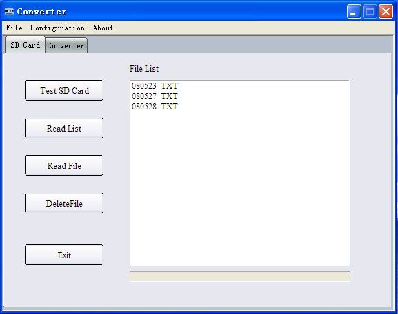
Sierra Instruction Manual                                                           Innova-Sonic® Model 205 Dedicated

                            Important Customer Notice
Thank you for choosing the Innova-Sonic® Model 205 Dedicated Transit-Time Ultrasonic Flow Meter with SLSI CMOS and
low-voltage wide-pulse sending technology. This manual contains important information about your meter. Before installing
and operating this flow meter, please read this manual carefully and follow its instructions.

    9 Sierra has verified the conformity between the contents in this manual and the hardware and software described.
        However, errors may still exist. We regularly review the materials covered in this manual and correct errors with
        revisions. Any suggestions for improvement will be appreciated.
    9 Go to www.sierrainstruments.com/products/downloads.html for a most current electronic version of this manual.
    9 We reserve the right to change the content of this manual without prior notification.
    9 If you have any questions or problems regarding this manual, please contact Sierra’s Customer Service

Department:
Toll Free: 800-866-0200 Phone: +831-373-0200 Fax: 831-373-4402
Email: service@sierrainstruments.com

WARNINGS IN THIS MANUAL
Warning, attention, and note statements are used throughout this book to draw your attention to important
information.

                 WARNING
                 “Warning” statement appears with information that is important to protect people and
                 equipment from damage. Pay very close attention to all warnings that apply to your application.
                 Failure to comply with these instructions may damage the meter and personal injury.

                 ATTENTION
                 “Attention” statements in this manual indicate that failure to comply with stated instructions
                 may result in damage to the meter or faulty operation of the flow meter.

                 NOTE
                 “Note” indicates that ignoring the relevant requirements or precautions may result in flowmeter
                 damage or malfunction.

IM-205 Rev. E2                                                                                                  Page 2 of 64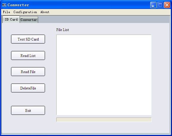
Sierra Instruction Manual                                                       Innova-Sonic® Model 205 Dedicated

© COPYRIGHT SIERRA INSTRUMENTS 2009
No part of this publication may be copied or distributed, transmitted, transcribed, stored in a retrieval system, or
translated into any human or computer language, in any form or by any means, electronic, mechanical, manual, or
otherwise, or disclosed to third parties without the express written permission of Sierra Instruments. The
information contained in this manual is subject to change without notice.

TRADEMARKS
Innova-Sonic® is a trademark of Sierra Instruments, Inc. Other product and company names listed in this manual
are trademarks or trade names of their respective manufacturers.

IM-205 Rev. E2                                                                                            Page 3 of 64

Sierra Instruction Manual                                                                                                   Innova-Sonic® Model 205 Dedicated

Product Components
An inspection should be made before installing the flow meter. Check to see if the spare parts are in accordance
with the packing list. Make sure that there is no damage to the enclosure due to a loose screw or loose wire, or
other damage that may have occurred during transportation. Any questions, please contact your representative as
soon as possible.

                            Transmitter                                                                                    Transducer

                        Innova-Sonic™Model 205
                            7   8   9    Menu

                            4   5   6       /+

                            1   2   3         /-

                            0             HIGH-PERFORMANCE LIQUID FLOWMETER
                                          ENT                        SQ       SS   Run

                                                                                          R

                            Accessory                                                                                      Document

       Pipe Strap      SD Card Reader Coupling compound

                                                                                                            1.   Instruction Manual
                                                                                                            2.   Packing List
                                                                                                            3.   Certified 3-Point Factory Calibration
                                                                                                            4.   Position drawing
                                                                                         Screws and         5.   Application Worksheet
       Screw Driver         Software                                                     plastic bushings

IM-205 Rev. E2                                                                                                                                           Page 4 of 64
Sierra Instruction Manual Innova-Sonic® Model 205 Dedicated
Content
1. Transmitter Installation and Connect .......................................................... 8
1.1. Inspection Prior to Transmitter Installation ......................................................................................... 8
1.2. Power Supply Connecting ................................................................................................................... 8
1.2.1. Direct Mount Method ..................................................................................................................... 8
1.2.2. Connecting the Wiring .................................................................................................................. 8
1.3. Powering on........................................................................................................................................ 8
1.4. Keypad Functions ............................................................................................................................... 9
1.5. Keypad Operation ............................................................................................................................... 9
1.6. Flowmeter Window Descriptions ........................................................................................................11
2. Pipe Parameter Entry Shortcuts ................................................................ 10
3. Measurement Site Selection ..................................................................... 12
4. Transducer Installation ............................................................................. 13
4.1. Installing the Transducers................................................................................................................. 13
4.1.1. Transducer spacing .................................................................................................................... 13
4.1.2. Transducer Mounting Methods.................................................................................................... 13
4.1.3. V Method..................................................................................................................................... 14
4.1.4. Z Method ..................................................................................................................................... 14
4.1.5. N Method (not commonly used) .................................................................................................. 14
4.1.6. W Method (very rarely used)........................................................................................................ 14
4.2. Transducer Mounting Inspection....................................................................................................... 15
4.2.1. Signal Strength Inspection .......................................................................................................... 15
4.2.2. Signal Quality (Q value) Inspection ............................................................................................. 15
4.2.3. Total Time and Delta Time Inspection.......................................................................................... 15
4.2.4. Transit Time Ratio ....................................................................................................................... 15
Warnings ............................................................................................................................. 16
5. Operating Instructions .............................................................................. 17
5.1. System Normal Identification format change of entire section ........................................................... 17
5.2. Zero Set Calibration .......................................................................................................................... 17
5.3. Scale Factor ...................................................................................................................................... 18
5.4. System Lock (Unlock) ....................................................................................................................... 18
5.5. Keypad Lock ..................................................................................................................................... 18
5.6. 4~20mA Current Loop Verification .................................................................................................... 19
5.7. Frequency Output ............................................................................................................................. 19
IM-205 Rev. E2 Page 5 of 64Sierra Instruction Manual Innova-Sonic® Model 205 Dedicated
5.8. Totalizer Pulse Output....................................................................................................................... 19
5.9. Alarm Programming .......................................................................................................................... 20
5.10. Batch Controller Paragraph format change ....................................................................................... 20
5.11. Analog Output Calibration................................................................................................................. 21
5.12. Use of The Memory Card ................................................................................................................... 21
5.12.1. Specifications ............................................................................................................................. 21
5.12.2. Install or Remove While the Meter is Powered ON ....................................................................... 22
5.12.3. Reading the SD Data Externally................................................................................................... 22
5.12.4. Reading the SD Data Internally With the Instrument Powered ON ................................................ 22
5.12.5. File Converter Tool ..................................................................................................................... 24
5.13 Recover the Factory Default .............................................................................................................. 25
5.14. ESN .................................................................................................................................................. 25
6. Windows Display Explanations ................................................................. 26
6.1. Windows Display Codes ................................................................................................................... 26
6.2. Display Explanation .......................................................................................................................... 27
7. Error Diagnoses ....................................................................................... 46
7.1. Table 1. Self-diagnoses and Error Solutions (upon power on) ........................................................... 46
7.2. Table 2. Error codes and solutions (during operation) ....................................................................... 47
7.3. Frequently Asked Questions and Answers ........................................................................................ 48
8. Product Overview ..................................................................................... 49
8.1. Introduction ...................................................................................................................................... 49
8.2. Features of Sierra Innova-Sonic® Model 205 Dedicated ..................................................................... 49
8.3. Theory of Operation .......................................................................................................................... 49
8.4. Applications...................................................................................................................................... 50
8.5. Specifications ................................................................................................................................... 51
9. Appendix1 - Flow Application Data ........................................................... 52
9.1. Sound Velocity and Viscosity for Fluids Commonly Used ................................................................. 52
9.2. Sound Velocity for Various Materials Commonly Used ...................................................................... 52
9.3. Sound Velocity In Water (1 atm) At Different Temperatures ............................................................... 53
10. Appendix 2 – Thermal Energy Meter ......................................................... 54
10.1. Thermal Energy Function .................................................................................................................. 54
10.2. Wiring ............................................................................................................................................... 54
10.3. Thermal Energy Calorimetry Method ................................................................................................. 54
10.4. Set Temperature Value Range ........................................................................................................... 55
11. Appendix 3 - Wetted Transducer ............................................................... 56
11.1. Overview ........................................................................................................................................... 56
11.2. Measurement Point Selection ............................................................................................................ 56
IM-205 Rev. E2 Page 6 of 64Sierra Instruction Manual Innova-Sonic® Model 205 Dedicated
11.3. Determining Transducer Spacing & Transducer Installation .............................................................. 57
11.4. Transducer Mounting Methods.......................................................................................................... 57
11.4.1. Z Mounting Method ..................................................................................................................... 58
11.4.2. V Mounting Method ..................................................................................................................... 58
11.4.3. W Mounting Method .................................................................................................................... 58
12. Appendix 4 - Serial Interface Network Use and Communications Protocol 59
12.1. Overview ........................................................................................................................................... 59
12.2. Serial Port Definitions ....................................................................................................................... 59
12.3. Direct Connection via RS232 To The Host Device.............................................................................. 60
12.4. Communication Protocol and the Use ............................................................................................... 60
12.4.1. Basic Commands ........................................................................................................................ 60
12.4.2. Function Prefix and Function Sign .............................................................................................. 61
12.5. Key Code .......................................................................................................................................... 62
Update Information:
__________________________________________________________________________________________
__________________________________________________________________________________________
__________________________________________________________________________________________
__________________________________________________________________________________________
IM-205 Rev. E2 Page 7 of 64Sierra Instruction Manual Innova-Sonic® Model 205 Dedicated
1. Transmitter Installation and Connect
1.1. Inspection Prior to Transmitter Installation
You will find a “Position
Drawing” in the packing. Please
use it as a template in the place 182 mm
that you are going to install the 7.17lnch
flow meter. Then drill 4
Position drawing
installation holes at the screw
position shown on the drawing Instrutions:
1. Place this template on the wall and drill 4 holes
4.72lnch
120 mm
with the 5.5mm aiguille. (right of 8mm diameter & 50mmdeep.
2. Insert a plastic bushing into each of the 4 holes.
picture) 3. Screw 4 ST5.5X50mm self tapping screws through the
transmitter enclosure base and attach it to the wall.
4. Tighten the screws to secure to the enclosure on the
wall.
Take out the enclosed screws and
plastic bushings. Insert the plastic
bushings into the installing holes.
Then open the two aluminum
pieces on the two sides of the top
Innova-Sonic™Model 205
cover. Put the flow meter into the
position and screw it in. (right 7 8 9 Menu
picture) 4 5 6 /+
1 2 3 /-
0 HIGH-PERFORMANCE LIQUID FLOWMETER
ENT SQ SS Run
R
ATTENTION
When installing please make sure that the installing face can afford the flow meter to avoid
falling off. And make sure the installing face is dry.
1.2. Power Supply Connecting
1.2.1. Direct Mount Method
Please double check that power supply you ordered meets your equipment requirements. Factory standard power
supply is 90~245 VAC.
IM-205 Rev. E2 Page 8 of 64Sierra Instruction Manual Innova-Sonic® Model 205 Dedicated
Observe the following precautions for installation procedures outlined in this chapter:
• Ensure that power connections are made in accordance with the indications shown on the connection
terminals.
• Transmitters can be powered by two different power supplies: 90~245VAC or 10-36VDC
1.2.2. Connecting the Wiring
Once the electronics enclosure has been installed, the flow meter wiring can be connected. Open the case,
terminals 11, 12, and 13 can be found at the left lower side. Connect to AC power. Terminal 11 is grounded (earth)
while connecting.
As per wiring diagram to connect 4-20mA Output (terminals 16, 17), Downstream transducer (terminals 18, 19,
20), Upstream transducer (terminals 21, 22, 23), Analog Input (terminals 24, 25, 26), OCT Output (terminals 27,
28) and Relay Output(terminals 29, 30).
For double-shielded transducer cable: "-" on the black wire, "+" on the red wire and "shield" on the shield.
AC Power 11 12 13 14 15 16 17 18 19 20 21 22 23 29 30
Shield Layer
Conductor
Conductor
Shield Layer
Conductor
Conductor
L N - + - + Relay
Output RS 232
AC IN DC IN 24 25 26 27 28 (RS 485)
AI2 AI1 GND - + - +
Power Input 4-20mA Down-Stream Up-Stream Analog OCT
Output Transducer Transducer Input Output
red wire
black wire
black wire
red wire
Down-Stream
Up-Stream
Blue Red
Bushing Bushing
Flow
WARNING
Wire with power off.
Use either AC or DC power supply. Do not connect them both at the same time.
1.3. Powering on
As soon as the flow meter is switched on, the self-diagnosis program will start to run. If any error is detected, an
error code will display on the screen (Refer - Error Diagnoses). After that, the system will run automatically
according to the last input parameters.
If the installation is accomplished when system is switched on, gain adjustment can be monitored in Window M01.
IM-205 Rev. E2 Page 8 of 64Sierra Instruction Manual Innova-Sonic® Model 205 Dedicated
After S1, S2, S3, and S4 are displayed on the upper left corner of the screen, the system will activate the normal
measurement condition automatically. It is indicated by code “*R” on the upper left corner of the screen.
The system will default to the last window settings and automatically display them at next power on.
1.4. Keypad Functions
Follow these guidelines when using the flow meter keypad (Refer to Keypad Figure):
0 ~ 9 And input numbers.
Backspace or delete characters to the left.
/+
And / - Return to the last menu or to open the next menu. These 7 8 9 Menu
buttons act as “+” and “-” functions when entering numbers. 4 5 6 /+
Menu
Select a menu. Press this key first, input two menu numbers and then 1 2 3 /-
enter the selected menu. For example, To Input a pipe outside diameter,
press 1 1 keys where “11” is the window ID to display the
Menu 0 ENT
parameter for pipe outside diameter.
1.5. Keypad Operation
With all of the parameters entered, the instrument setup and measurement displays are subdivided or consolidated
into more than 100 independent windows. The operator can input parameters, modify settings or display
measurement results by “visiting” a specific window. These window are arranged by 2-digit serial numbers
(including “+” sign) from 00~99, then to +0, +1, etc. Each window serial number, or so-called window ID code,
has a defined meaning. For example, Window M11 indicates the parameter input for pipe outside diameter, while
Window M25 indicates the mounting spacing between the transducers, etc. (Refer – Windows Display
Explanations).
The keypad shortcut to visit a specific window is to press the Menu
key at any time, then input the 2-digit window
ID code. For example, to input or check the pipe outside diameter, just press the Menu
1 1 keys for window ID
code 11.
Another method to visit a particular window is to press / + /-
and ENT keys to scroll the screen. For example,
if the current window ID code is 66, press /+
key to enter Window M65, press the / + button again to enter
Window M64; then, press the /-
key to back Window M65, and press the / - key again to enter Window
M66.
Example 1: To enter a pipe outside diameter of
219.234, the procedure is as follows: Pi p e Ou t e r Di a me t e r
Press 1 1 keys to enter Window M11 (the
Menu >_
numerical value displayed currently is a previous
value). Now press ENT key. The symbol “>” and
the flashing cursor are displayed at the left end of the
second line on the Screen. The new value can be
entered then…
2 1 9 2 3 4 ENT
Example 2: If the pipe material is “Stainless Steel”, the selection. It is possible to press the 1 key to
press keys 1 4 to enter Window M 14 first.
Menu
change the selection and wait until “1. Stainless Steel”
Then press ENT
key to modify the options. Now, is displayed on the second line of the screen. Then
select the “1. Stainless Steel ” option by pressing / + press the ENT key to confirm.
and / - keys, and then press ENT key to confirm
IM-205 Rev. E2 Page 9 of 64Sierra Instruction Manual Innova-Sonic® Model 205 Dedicated
Pi p e Ma t e r i a l [ 14 Pi p e Ma t e r i a [ 14
>1. St a i n le s s St e e l >5 . PVC
ATTENTION
Generally, press ENT key first if operator wants to enter “modify” condition. If the “modify” is
still not possible even after pressing the ENT key, it means that system is locked by a password.
To “Unlock” it, select “Unlock” in Window M47 and enter the original password. The keypad will
not respond if the keypad is locked. It only can be unlocked by the entering original password.
Select keypad lock functions in Window M48.
1.6. Flowmeter Window Descriptions
The Flowmeter has the unique feature of windows processing for all operations.
These windows are assigned as follows:
00~09 Flow Totalizer Display: to display flow rate, positive total, negative total, net total, velocity, date &
time, analog inputs for present flow, present operation and flow results today, etc.
10~29 Initial Parameter Setup: to enter pipe outside diameter, pipe wall thickness, fluid type, transducer type,
transducer mounting and spacing, etc.
30~38 Flow Units Options: to select the flow unit, totalizer unit, measurement unit, turn totalizers on/off and
reset totalizes, etc.
40~49 Setup options: Scaling factor, network IDN (Window M46), system lock (Window M47) and keypad
lock code (Window M48), etc.
50~89 Input and output setup: relay output setup, 4-20mA outputs, flow batch controller, LCD backlit option,
date and time, low/high output frequency, alarm output, date totalizer, etc.
90~95 Diagnoses: Signal strength and signal quality (Window M90), TOM/TOS*100 (Window M91), flow
sound velocity (Window M92), total time and delta time (Window M93), Reynolds number and factor
(Window M94), Data Interval (Window M95) etc.
+0~+5 Appendix: power on/off time, total working hours, on/off times and a single-accuracy function
calculator.
ATTENTION
The other windows are for hardware adjustment by the manufacturer.
IM-205 Rev. E2 Page 11 of 64Sierra Instruction Manual Innova-Sonic® Model 205 Dedicated
2. Pipe Parameter Entry Shortcuts
Below is an example of a typical shortcut keypad entry for pipe parameters. For example the parameters in this
example are: measuring the diameter of DN200, measuring medium is water, pipe material is carbon steel, no liner
material. This example can be operated as follows:
Step1. Pipe outside diameter:
Press 1 1 keys to enter Window M11,
Menu
and enter the pipe outside diameter, and then
press the ENT key.
Pi p e Ou t e r Di a me t e r
2 0 0 mm
Step2. Pipe wall thickness
Press the / - 1 2 key to enter Window
M12, pipe wall thickness, and press the ENT
key.
Pipe Wall Thickness
6 mm
Step3. Pipe material
Pi p e Ma t e r i a l [ 14
Press the / - 1 4 key to enter Window
M14, press the ENT
key, move the / + or 0 . Ca r b o n St e e l
/-
key to select pipe material, and press the
ENT
key.
Step4. Liner material parameters
(including thickness and sound velocity, if
Li nner Ma t e r i a l [ 16
needed) 0 . No n e , No L i n e r
Press the / - 1 6 key to enter Window
M16, press the ENT key, move the / + or
/-
key to select liner material, and press the
ENT
key.
Step5. Fluid type
F lu i d Ty p e [20
Press the / - 2 0 key to enter Window
M20, press the ENT key, move the / + or 0. Wa t e r
/-
key to select fluid type, press the ENT
key.
IM-205 Rev. E2 Page 10 of 64Sierra Instruction Manual Innova-Sonic® Model 205 Dedicated
Step6. Transducer type
(The transmitter is available for various
Tr a n s d u c e r Ty p e [ 2 3
transducer types.) 0 . St a n d a r d
Press the / - 2 3 key to enter Window
M23, press the ENT
key, move the / + or
/-
key to select transducer type, and press
the ENT key.
Step7. Transducer mounting methods
T r a n s d u c e r Mo u n t i n g
Press the / - 2 4 key to enter Window
M24, press the ENT
key, move the / + or 0. V
/-
key to select transducer-mounting method,
and press the ENT key.
Step8. Adjust Transducer spacing
Transducer Spacing
Press the / - 2 5 key to enter Window
M25, accurately install the transducer 159.86 mm
according to the displayed transducer
mounting spacing and the selected mounting
method (Refer to Installing the Transducers in
this chapter).
Step9. Display measurement result
Press the 0 1 keys to enter Window
Menu
M01 to display measurement result.
F lo w 0 .112 9 m3 / h *R
Ve l 1.0 4 15 m/ s
IM-205 Rev. E2 Page 11 of 64Sierra Instruction Manual Innova-Sonic® Model 205 Dedicated
3. Measurement Site Selection
When selecting a measurement site, it is important to select an area where the fluid flow profile is fully developed
to guarantee a highly accurate measurement. Use the following guidelines to select a proper measurement
installation site:
1. Choose a section of pipe, which is always full of liquid, such as a vertical pipe with flow in the upward
direction or a full horizontal pipe.
PUMP
CHECK VALVE
GOOD
5D
10D
Storage Tank
MAY BE
(If Pipe Full)
NEVER
GOOD
10D 5D
The site should have a straight pipe run length equal to at least 10 pipe diameters upstream and 5 pipe diameters
downstream from any throttling valves or other flow disturbance producing elements, such as pipe reducers,
elbows, tees, etc.
2. Ensure that the pipe surface temperature at the measuring point is within the transducer temperature limits.
3. Consider the inside condition of the pipe carefully. If possible, select a section of pipe where the inside is
free excessive corrosion or scaling.
4. Choose a section of sound conducting pipe.
Examples acceptable measurement site selection is illustrated on the figure on the below.
GOOD
5D
10D
NEVER 10D 5D
10D 5D
GOOD
5D
NEVER GOOD
10D 5D D
10
GOOD
IM-205 Rev. E2 Page 12 of 64Sierra Instruction Manual Innova-Sonic® Model 205 Dedicated
4. Transducer Installation
4.1. Installing the Transducers
Before installing the transducers, clean the pipe surface where the transducers are to be mounted. Remove any rust,
scale or loose paint and make a smooth surface. Choose a section of sound conducting pipe for installing the
transducers. Apply a wide band of sonic coupling compound down the center of the face of each transducer as
well as on the pipe surface, and then attach the transducers to the pipe with the straps provided and tighten them
securely.
NOTE
The two transducers should be mounted at the pipe’s centerline on horizontal pipes.
Make sure that the transducer mounting direction is parallel with the flow.
During the installation, there should be no air bubbles or particles between the transducer and
the pipe wall. On horizontal pipes, the transducers should be mounted in the 3 o’clock and 9
o’clock positions of the pipe section in order to avoid any air bubbles inside the top portion of
the pipe. (Refer to Transducer Mounting). If the transducers cannot be mounted horizontally
symmetrically due to limitation of the local installation conditions, it may be necessary to mount
the transducers at a location where there is a guarantee full pipe condition (the pipe is always
full of liquid).
4.1.1. Transducer spacing
After entering the required parameters, the spacing between the ENDS of the two transducers is considered as the
standard transducer spacing (Refer to Top View on transducer mounting methods in diagram below). Check the
data displayed in Window M25 and space the transducers accordingly.
4.1.2. Transducer Mounting Methods
Four transducer mounting methods are available. They are respectively: V method, Z method, N method, and W
method. The V method is primarily used on small diameter pipes (DN100~400mm, 4”~16”). The Z method is
used in applications where the V method cannot work due to poor signal or no signal detected. In addition, the Z
method generally works better on larger diameter pipes (over DN300mm, 12”) or cast iron pipes.
The N method is an uncommonly used method as well as is the W method. They are used on smaller diameter
pipes (below DN50mm, 2”).
IM-205 Rev. E2 Page 13 of 64Sierra Instruction Manual Innova-Sonic® Model 205 Dedicated
4.1.3. V Method
The V method is considered as the standard method. The V method usually gives a more accurate reading and is
used on pipe diameters ranging from 25mm to 400mm (1~16”) approximately. Also, it is convenient to use, but
still requires proper installation of the transducer, contact on the pipe at the pipe’s centerline, and equal spacing on
either side of the centerline.
Side View Section Top View
Upstream Transducer Transducer
Flow
Flow
Downstream Transducer Pipe Strap Transducer Space
4.1.4. Z Method
The signal transmitted in a Z method installation has less attenuation than a signal transmitted with the V method.
This is because the Z method utilizes a directly transmitted (rather than reflected) signal which transverses the
liquid only once.
The Z method is able to measure on pipe diameters ranging from 100mm to 3000mm (4”~120”) approximately.
Therefore, we recommend the Z method for pipe diameters over 300mm (12”).
Side View Section Top View
Upstream Transducer Transducer
Flow
Flow
Downstream Transducer Pipe Strap Transducer Spacing
4.1.5. N Method (not commonly used)
With the N method, the sound waves traverse the fluid twice and bounce three times off the pipe walls. It is
suitable for small pipe diameter measurement.
The measurement accuracy can be improved by extending the transit distance with the N method (uncommonly
used).
Side View Section Top View
Upstream Transducer Transducer
Flow
Flow
Downstream Transducer Pipe Strap Transducer Spacing
4.1.6. W Method (very rarely used)
As with the N method, the measurement accuracy can also be improved by extending the transit distance with the
W method. The sound wave traverses the fluid four times and bounces four times off the pipe walls. It is suitable
IM-205 Rev. E2 Page 14 of 64Sierra Instruction Manual Innova-Sonic® Model 205 Dedicated
for very small pipe (diameters less than 50mm, 2”).
Side View Section Top View
Upstream Transducer Transducer
Flow
Flow
Downstream Transducer Pipe Strap Transducer Spacing
4.2. Transducer Mounting Inspection
Check to see if the transducer is installed properly and if there is an accurate and strong enough ultrasonic signal
to ensure proper operation and high reliability of the transducer. You can confirm that the transducer is installed
correctly by checking the detected signal strength, total transit time, and delta time as well as transit time ratio.
The “mounting” condition directly influences the flow value accuracy and system long-time running reliability. In
most instances, only apply a wide bead of sonic coupling compound lengthwise on the face of the transducer and
stick it to the outside pipe wall to get good measurement results. However, the following inspections still need to
be carried out in order to ensure the high reliability of the measurement and long-term operation of the instrument.
4.2.1. Signal Strength Inspection
Signal strength (displayed in Window M90) indicates a detected strength of the signal both from upstream and
downstream directions. The relevant signal strength is indicated by numbers from 00.0~99.9. 00.0 represents no
signal detected while 99.9 represent maximum signal strength. Normally, the stronger the signal strength detected,
the longer the operation of the instrument reliably, as well as the more stable the measurement value obtained.
Adjust the transducer to the best position and check to ensure that enough sonic coupling compound is applied
adequately during installation in order to obtain the maximum signal strength. The Innova-sonic’s system
normally requires signal strength over 60.0, which is detected from both upstream and downstream directions. If
the signal strength detected is too low, the transducer installation position and the transducer mounting spacing
should be re-adjusted and the pipe should be re-inspected. If necessary, change the mounting to the Z method.
4.2.2. Signal Quality (Q value) Inspection
Q value is short for Signal Quality (displayed in Window M90). It indicates the level of the signal detected. Q
value is indicated by numbers from 00~99. 00 represents the minimum signal detected while 99 represent the
maximum. Normally, the transducer position should be adjusted repeatedly and coupling compound application
should be checked frequently until the signal quality detected is as strong as possible.
4.2.3. Total Time and Delta Time Inspection
“Total Time and Delta Time”, which displays in Window M93, indicates the condition of the installation. The
measurement calculations in the flow meter are based upon these two parameters. Therefore, when “Delta Time”
fluctuates widely, the flow and velocities fluctuate accordingly. This means that the signal quality detected is too
poor. It may be the results of poor pipe-installation conditions, inadequate transducer installation, or incorrect
parameter input. Generally, “Delta Time” fluctuation should be less than±20%. Only when the pipe diameter is
too small or velocity is too low can the fluctuation be wider.
4.2.4. Transit Time Ratio
Transit Time Ratio indicates if the transducer mounting spacing is accurate. The normal transit time ratio should
be 100±3 if the installation is proper. Check it in Window M91.
IM-205 Rev. E2 Page 15 of 64Sierra Instruction Manual Innova-Sonic® Model 205 Dedicated
ATTENTION
If the transit time ratio is over 100±3, it is necessary to check:
(1) If the parameters (pipe outside diameter, wall thickness, pipe material, liner, etc.) have
been entered correctly,
(2) If the transducer mounting spacing is accordance with the display in Window M25,
(3) If the transducer is mounted at the pipe’s centerline on the same diameter,
(4) If the scale is too thick or the pipe mounting is distorted in shape, etc.
Warnings
(1) Pipe parameters entered must be accurate; otherwise the flow meter will not work properly.
(2) During the installation, apply enough coupling compounds in order to stick the transducer onto the
pipe wall. While checking the signal strength and Q value, move the transducer slowly around the
mounting site until the strongest signal and maximum Q value can be obtained. Make sure that the
larger the pipe diameter, the more the transducer should be moved.
(3) Check to be sure the mounting spacing is accordance with the display in Window M25 and the
transducer is mounted at the pipe’s centerline on the same diameter.
(4) Pay special attention to those pipes that formed by steel rolls (pipe with seams), since such pipe is
always irregular. If the signal strength is always displayed as 0.00, that means there is no signal
detected. Thus, it is necessary to check that the parameters (including all the pipe parameters) have
been entered accurately. Check to be sure the transducer mounting method has been selected properly,
the pipe is not worn-out, and the liner is not too thick. Make sure there is there is indeed fluid in the
pipe or the transducer is not very close to a valve or elbow, and there are not too many air bubbles in
the fluid, etc. With the exception of these reasons, if there is still no signal detected, the measurement
site has to be changed.
(5) Make sure that the flowmeter is able to run properly with high reliability. The stronger the signal
strength displayed, the higher the Q value reached. The longer the flowmeter runs accurately, the
higher the reliability of the flow rates displayed. If there is interference from ambient electromagnetic
waves or the signal detected is too poor, the flow value displayed is not reliable; consequently, the
capability for reliable operation is reduced.
(6) After the installation is complete, power on the instrument and check the result accordingly.
IM-205 Rev. E2 Page 16 of 64Sierra Instruction Manual Innova-Sonic® Model 205 Dedicated
5. Operating Instructions
5.1. System Normal Identification format change of entire section
Press the Menu
0 8 keys. If the letter “*R” displays on the screen, it indicates system normal.
If the letter “E” is displayed, it indicates that the current loop output is over ranged by 120%. This refers to the
settings in Window M57. Enter a larger value in Window M57, and the letter “E” will disappear. It can be ignored
if no current loop output is used.
If the letter “Q” is displayed, it indicates that the frequency output is over ranged by 120%, and this refers to the
settings in Window M69. Increase the input value in Window M69, and the letter “Q” will disappear. It can be
ignored if no frequency output is used.
If the letter “H” is displayed, it indicates that the ultrasonic signal detected is poor. For more information, please
refer to “Error Diagnoses”.
If the letter “G” is displayed, it indicates that system is adjusting the signal gain prior to the measurement. Also, it
means system normal. Only when the adjustment takes too long without stopping, can system be identified as
abnormal.
Letter “I” indicates no signal is being detected. Check the transducer wiring connections are correct, the
transducers are installed firmly, etc.
Letter “J” indicates a hardware defect exists. Normally, such defect is temporary; it could be eliminated by system
reboot (power off and restart). For further information, please refer to “Error Diagnoses”.
5.2. Zero Set Calibration
Once zero flow occurs, a zero point may indicate on each measuring instrument, i.e. as the measurement value
reaches zero flow, it is indicated as zero. It is necessary to establish the true zero flow condition and program that
set point into the instrument.
If the zero set point is not at true zero flow, a measurement difference may occur. The smaller the physical
measurement capacity is, the larger the measurement difference from the zero point will exist. Only when zero
point is reduced to a definite degree, as compared with the physical measurement capacity, can the measuring
difference from zero point be ignored.
NOTE
For an ultrasonic flow meter, the measurement difference from zero point cannot be ignored at
low flow. It is necessary to perform a zero set calibration to improve low flow measurement
accuracy.
IM-205 Rev. E2 Page 17 of 64Sierra Instruction Manual Innova-Sonic® Model 205 Dedicated
5.3. Scale Factor
Scale factor refers to the ratio between “actual value” and “reading value”. For example, when the measurement is
2.00, and it is indicated as 1.98 on the instrument, the scale factor reading is 2/1.98. This means that the best scale
factor constant is 1. However, it is difficult to keep the scale factor as “1” on the instrument especially in batch
control operations. The difference is called “consistency”. High quality products always require high consistency.
The scale factor default is “1” for each instrument prior to shipment from the factory. The reason setting the scale
factor default is that the scale factors in the flow meter are only limited by two parameters: the crystal oscillation
frequency and the transducer. It has no relation to any circuit parameters.
During operation, there still exists possible difference in pipe parameters, etc. The “scale factor” may be necessary
when used on different pipes. Thus, scale factor calibration is specially designed for calibrating the differences
that result from application on different pipes. The scale factor entered must be one that results from actual
calibration.
5.4. System Lock (Unlock)
System lock is readable but unable to prevent operation error due to unauthorized tampering by unauthorized
personnel.
Press the 4 7 ENT keys, move / + or
Menu /-
key to select “Lock”, press the ENT
key, enter a 1~4
numerically long password, and then press the ENT
key to confirm.
Unlock using the selected password only. Press 4 7
Menu ENT
, move /+
or /-
to select “Unlock”, press
ENT
, enter the correct password, then press ENT to confirm.
ATTENTION
Keep the password in mind or recorded in a safe place or the instrument cannot be used.
5.5. Keypad Lock
The keypad can be locked to prevent unauthorized use of your flow meter. Unlock it using the correct password
only.
To lock it, first enter desired window, then press 4 8 press ENT to enter a 1~8 numerically long
Menu
password, and then it will return to the locked window automatically. For example, if Window M01 is required to
display in the locked condition, enter Window M01 first (if already in this window, skip this step), press
Menu
4 8 , press ENT to enter a password such as “12345678”, press ENT again to return to the locked
Window M01 automatically. The keypad is “invalidated” now. Unlock it by entering the password “12345678”
again.
IM-205 Rev. E2 Page 18 of 64Sierra Instruction Manual Innova-Sonic® Model 205 Dedicated
5.6. 4~20mA Current Loop Verification
Possessing a current loop output exceeding an accuracy of 0.1%, the flow meter is programmable and
configurable with multiple output modules such as 4 ~20mA or 0~20mA. Select in Window M55. For details,
please refer to “Windows Display Explanations”.
In Window M56, enter a 4mA flow value. Enter the 20mA flow value in Window M57. For example, if the flow
range in a specific pipe is 0~1000m3/h, enter 0 in Window M56 and 1000 in Window M57. If the flow ranges
from -1000~0~2000m3/h, configure the 20~4~20mA module by selecting Window M55 when flow direction is
not an issue. Enter 1000 in Window M56 and 2000 in Window M57. When flow direction is an issue, module
0~4~20mA is available. When the flow direction displays as negative, the current output is in range of 0~4mA,
whereas the 4~20mA is for the positive direction. The output module options are displayed in Window M55. Enter
“-1000” in Window M56 and 2000 in Window M57.
Calibrating and testing the current loop is performed in Window M58. Complete the steps as follows:
Press Menu
5 8 ENT , move / + or / - to display “0mA”, “4mA”, “8mA”, “16mA”, “20mA” readings,
connect an ammeter to test the current loop output and calculate the difference. Calibrate it if the difference is
within tolerance. If not, how to calibrate the current loop is to be found in Section 5.11 in this chapter.
Check the present current loop output in Window M59 as it changes along with change in flow.
5.7. Frequency Output
The flow meter is provided with a frequency output transmitter function. The high or low frequency output
displayed indicates the high or low flow rate reading. The user can reset the frequency output as well as flow rate
per his requirements For example: if a pipe flow range is 0~3000m3/h, the relative frequency output required is
123~1000Hz, and the configuration is as follows:
In Window M68 (low limit frequency output flow value), input 0;
In Window M69 (high limit frequency output flow value), input 3000;
In Window M67 (low limit frequency), input 123
There is no output circuit specially assigned to frequency output. It only can be transmitted through OCT, i.e.
select Window M78 (item “13. FO”).
5.8. Totalizer Pulse Output
Each time the flowmeter reaches a unit flow, it may generate a totalizer pulse output to a remote counter. To
configure the unit flow, please refer to Windows M32 and M33.
The totalizer pulse output can be transmitted through OCT or a relay. So, it is necessary to configure OCT and the
relay accordingly. (Please refer to Window M78 and M79).
For example, if it is necessary to transmit the positive totalizer pulse through a relay, and each pulse represents a
flow of 0.1m3, ; the configuration is as follows:
In Window M33, select totalizer the flow unit “Cubic Meters (m3)”;
In Window M34, select the scale factor “x0.1”;
In Window M79, select “9. Positive totalizer pulse output”
IM-205 Rev. E2 Page 19 of 64Sierra Instruction Manual Innova-Sonic® Model 205 Dedicated
ATTENTION
Make sure to select a suitable totalizer pulse, since the output may be extended if it is too large.
If it is too small, the relay may activate too frequently and may probably shorten its life.
Furthermore, if it operates too fast, it may generate a pulse loss error. Therefore, a rate of
1~60/minute is recommended.
5.9. Alarm Programming
The flow meter has two programmable alarms: audible alarm and on off output alarm. The audible alarm
generates an internal beeper. Select the BEEPER trigger in Window M77. The on-off output alarm is generated
through OCT or transmission to an external circuit by opening or closing a relay. The on-off output signal is
activated under the following conditions:
(1) Signal not detected
(2) Poor signal detected
(3) The flow meter is not ready for normal measurement
(4) The flow is in the reverse direction (back flow)
(5) The analog outputs exceed span by 120%
(6) The frequency output exceeds span by 120%
(7) The flow rate exceeds the ranges configured (Configure the flow ranges using the software alarm system.
There are two software alarms: Alarm#1 and Alarm #2. The lower limit value for Alarm#1 is configured
in Window M73, and the upper limit value is configured in Window M74. As for Alarm#2, the lower
limit value is in M75 and the upper one is in Window M76).
Example 1: To program audible alarm, activated when the flow meter is not ready for normal measurement:
Select item 2 in Window M77: “2. NO*R”.
Example 2: To program the relay output alarm, activated when flow rate exceeds 300~1000m3/h:
(1) In Window M73, input 300
(2) In Window M74, input 1000
(3) In Window M79, select item 6: “6. Alarm #1 limit exceed”
Example 3: To program OCT output alarm signal, activated when flow rate exceeds 100~500m3/h; relay output
alarm signal activated when flow rate exceeds 600~1000m3/h:
(1) In Window M73, input 100
(2) In Window M74, input 500
(3) In Window M75, input 600
(4) In Window M76, input 1000
(5) In Window M78, select item 6: “6. Alarm #1”
(6) In Window M79, select item 7: “7. Alarm #2”
5.10. Batch Controller Paragraph format change
The batch controller is able to perform flow quantity control, or the batching of specific volumes to control events
in product production or chemical dosing, etc. The internal batch controller in the flow meter is able to take the
high or low end of analog input signals as an input, or through the keypad, to perform control functions. The
output can be transmitted through OCT or a relay.
When taking analog inputs as control signals, input an analog output which is over 2mA through the analog input
terminal to indicate the condition of “1”; current “0” indicates the condition of “0”.
IM-205 Rev. E2 Page 20 of 64Sierra Instruction Manual Innova-Sonic® Model 205 Dedicated
In Window M78(OCT output )、M79(relay output) or M80(Flow Batch CTRL), select Item 8 “Batch controller”
and the OCT or relay output will generate output signals. Enter the batch value in Window M81. Start the batch
controller after that. For details, please refer to “Windows Display Explanations”.
5.11. Analog Output Calibration
ATTENTION
Each flow meter has been calibrated strictly before leaving factory. It is unnecessary to carry
through this step except when the current value (detected while calibrating the current loop)
displayed in Window M58 is not identical with the actual output current value.
The hardware detect window must be activated prior to calibration. The procedure is as follows:
1. Press /-
Menu
0 ENT enter password “4213068”, then press ENT to activate the detect menu. With no
effect to next power on, this window will close automatically as soon as the power is turned off.
2. Press /-
Menu
1 ENT to calibrate the current loop 4mA output. Use an ammeter to measure the current
loop output current. At the same time, move / + or / - to adjust the displayed numbers. Watch the
ammeter until it reads 4.00. Stop at this point, the 4mA has been calibrated.
3. Then, press ENT
to calibrate the current loop 20mA output. The method is as same as in 4mA calibration.
4. The results is saved in EEPROM. Switch off the power supply has not lost.
5.12. Use of The Memory Card
5.12.1.Specifications
• Memory: 1GB (Standard)
• Data collection update rate: User Selectable: 2 seconds to 13000 seconds (3.6 hours). .
• Data content: date and time, flow, velocity, cumulated flow, positive totalizer, negative totalizer, heat
quantity
• File system format: FAT16
• File type: plain text file (.txt)
• File number: maximum 512pcs
• Filename format: yymmdd (yy - year, mm - month, dd - date)
• SD Data format:
1= yy-mm-dd, hh:mm:ss
2= +3.845778E+01m3/h
3= +1.451074E+00m/s
4= -0000010E+0m3
5= +0000002E+0m3
6= -0000012E+0m3
7=+7.1429E-01KJ/s
IM-205 Rev. E2 Page 21 of 64Sierra Instruction Manual Innova-Sonic® Model 205 Dedicated
8=+3.9721E+03KJ
9=+4.573242E+01
10=+4.338866E+01
It can save 120bytes of data each time. When the capacity of the SD card is full, the new data will override the
earliest files automatically.
5.12.2.Install or Remove While the Meter is Powered ON
If the operator desires to insert or remove the SD card with the flow meter’s power on, the following instructions MUST
be followed:
1. Turn the Transferred switch to the “Off” position, as shown in the picture below.
2. The “Memory” indicator light should be OFF. WARNING: Do not remove SD card if the memory light is on.
3. Once the “Memory” light is off, it is then safe to remove or install the SD Card.
4. Once reinstalled, turn the transferred switch “ON”, note the “Memory” light should now be on. The SD Card
can now continue to log data.
Digital Correlation Transit-Time Flowmeter
Memory
Insert The
Memory
Card Here Do not insert or remove the Memory card when the Memory light is on.
TM
OFF ON
5.12.3.Reading the SD Data Externally
Remove the SD card from the flow meter. The operator may then use a PC carder reader to read the data in the
card. On the PC the operator can save, edit and print the data in the SD card, and then recall and analyze the data.
Care should be taken while working with the data on the SD card on a PC.
ATTENTION
Do not remove the SD card from the reader while actively working with the data. Data should
be saved and stored in a separate location on the PC, and then processed form that file location.
processing the data directly from the SD card file location on the PC could result in lost or
corrupt data if the SD card is removed while still being processed.
5.12.4. Reading the SD Data Internally With the Instrument Powered ON
1. Open the cover of the meter; connect the flow meter to a PC via RS232. The operator can read and work
with the data in the SD card with the “Convertor” software provided with the flow meter.
IM-205 Rev. E2 Page 22 of 64Sierra Instruction Manual Innova-Sonic® Model 205 Dedicated
2. Select “Comm. Setup”, Set up communications port (Generally COM1) and baud rate.
3. After connecting on flow meter, shown below (If not connected to flow meter, you can click on "Offline" button
interface into the document conversion):
Due to the expanded memory (EMS) capacity of the flow meter is extremely small as compared with the SD
memory card.; the transfer speed is rather slow for some commands.
ATTENTION
We suggest: it is better to read the SD data externally (remove the card from the flow meter to
insert it into your PC).
IM-205 Rev. E2 Page 23 of 64Sierra Instruction Manual Innova-Sonic® Model 205 Dedicated
(1) Click "Test SD card." If the SD card is working, a message will pop up on the lit panel of the LED
stating “The SD card is OK.”
(2) Click on "Read list" to return to the SD card catalog of all the documents.
(3) Then click on "Read File." A reading of the progress of the document should appear.
After the reading, will pop up "The File has been read" window and Convertor.exe the root directory of storage or
set up by reading the paper and check the contents of the file format is normal. NOT SURE what is we are trying
to say here. This needs to be explained better.
Return to the directory, select a file (such as 080523. TXT), then click the "Delete File", then delete confirmed
that the successful return to delete to delete success tips, if chosen by the paper as a document of the day, then
returned to tips cannot be deleted.
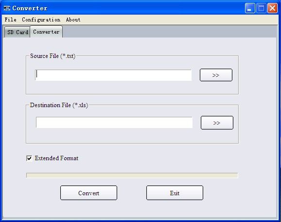
5.12.5.File Converter Tool
The files saved in the SD card are in text format (.TXT). If the operator desires to convert it to Excel format
(.XLS), the file-conversion tool (TTOE.EXE) may be found in the CD shipped with the flow meter. This program
must be run in the WINDOWS operating system, the interface is as follows:
Select the file to be converted in “Source File (*.txt), enter the directory path and the filename in “Destination File
(*.xls), then press “Convert”. The conversion is completed.
IM-205 Rev. E2 Page 24 of 64You can also read