BRIDGE AMPLIFIERS Owner's Guide - ADInstruments
←
→
Page content transcription
If your browser does not render page correctly, please read the page content below
BRIDGE
AMPLIFIERS
  Owner’s Guide
This document was, as far as possible, accurate at the time of release. However, changes may have been
made to the software and hardware it describes since then. ADInstruments NZ Limited reserves the right
to alter specifications as required. Late-breaking information may be supplied separately.

Trademarks of ADInstruments
PowerLab®, LabChart® and ADInstruments® are registered trademarks of ADInstruments NZ Limited.

Other Trademarks
Apple, Mac and Macintosh are registered trademarks of Apple Computer, Inc.
Windows, Windows 7, Windows 8, Windows 10 and Windows Vista are either registered trademarks or
trademarks of Microsoft Corporation.
All other trademarks are the property of their respective owners.

Document Number: U-BGA/OG-01 Rev C, Date of issue: 06/20

Copyright © ADInstruments NZ Limited, 2020. All rights reserved. PowerLab, LabChart and ADInstruments
are registered trademarks of ADInstruments NZ Limited. Windows 8, Windows 7, Windows 10, Windows
Vista and .NET Framework are trademarks of Microsoft Corporation. Apple, the Apple logo, MacOS, and
Macintosh are trademarks of Apple Computer Inc. registered in the U.S. and other countries. Acrobat and
Adobe are registered trademarks of Adobe Systems Incorporated. Igor is a trademark of Wavemetrics Inc.
MATLAB is a registered trademark of The MathWorks Inc. Grass is a trademark of Astro-Med Inc. All other
trademarks are the property of their respective owners.

Web: www.adinstruments.com

Manufactured in Australia by:
ADInstruments (Sydney) Pty. Ltd.,
13/22 Lexington Drive
Bella Vista 2153 New South Wales

Technical Support: support.au@adinstruments.com

ii                                                                                    Owner’s Guide
Chapter 1

    Safety Notes
    Statement of Intended Use
    All products manufactured by ADInstruments are intended for use in teaching and
    research applications and environments only. ADInstruments products are NOT
    intended to be used as medical devices or in medical environments. That is, no product
    supplied by ADInstruments is intended to be used to diagnose, treat or monitor a
    subject. Furthermore no product is intended for the prevention, curing or alleviation of
    disease, injury or handicap. ADInstruments products are intended to be installed, used
    and operated under the supervision of an appropriately qualified life-science researcher.
    The typical usage environment is a research or teaching lab or hospital. ADInstruments
    equipment is not intended for use in domestic environments.
    Where a product meets IEC 60601-1 it is under the principle that:
        • this is a more rigorous standard than other standards that could be chosen.
        • it provides a high safety level for subjects and operators.

    The choice to meet IEC 60601-1 is in no way to be interpreted to mean that a product:
        • is a medical device,
        • may be interpreted as a medical device, or
        • is safe to be used as a medical device.

    Safety and Quality Standards
    When used with ADInstruments isolated front-ends, PowerLab systems are safe for
    connection to subjects. The FE231 Bio Amp, FE232 Dual Bio Amp and FE234/FE238
    Quad/Octal Bio Amps front-ends conform to international safety requirements.
    Specifically these are IEC60601-1 and its addenda (Safety Standards, page 3) and
    various harmonized standards worldwide (CSA601.1 in Canada and AS/NZS 3200.1 in
    Australia and New Zealand).
    In accordance with European standards they also comply with the electromagnetic
    compatibility requirements under IEC60601-1-2, which ensures compliance with the
    EMC directive.

1                                                                          Owner’s Guide
Quality Management System ISO 9001:2008
ADInstruments manufactures products under a quality system certified as complying
with ISO 9001:2008 by an accredited certification body.
Regulatory Symbols
Amplifiers and signal-conditioners manufactured by ADInstruments that are designed
for direct connection to humans and animals are tested to IEC60601-1:2012 (including
amendments 1 and 2), and carry one or more of the safety symbols below. These
symbols appear next to those inputs and output connectors that can be directly
connected to human subjects.
BF (body protected) symbol. This means that the input connectors
are suitable for connection to humans and animals provided there is no
direct electrical connection to the heart.
Warning symbol. The exclamation mark inside a triangle means that the
!
supplied documentation must be consulted for operating, cautionary or
safety information before using the device.
CE Mark. All front-end amplifiers and PowerLab systems carry the CE
mark and meet the appropriate EU directives.
Refer to booklet symbol. This symbol specifies that the user needs
to refer to the Instruction manual or the booklet associated with the
device.
Date of Manufacture/ Manufacturer’s name symbol. This symbol
indicates the date of manufacture of the device and the name of the
manufacturer
WEEE directive symbol. Unwanted equipment bearing the Waste
Electrical and Electronic Equipment (WEEE) Directive symbol requires
separate waste collection. (See disposal section at the end of this
chapter)
Further information is available on request.
2 Owner’s GuideSafety Standards
IEC Standard - International Standard - Medical Electrical Equipment
IEC 60601-1-1:2000 Safety requirements for medical electrical systems
IEC 60601-1:2012 + A1 General requirements for safety
General Safety Instructions
To achieve the optimal degree of subject and operator safety, consideration should
be given to the following guidelines when setting up a PowerLab system either as
stand-alone equipment or when using PowerLab equipment in conjunction with other
equipment. Failure to do so may compromise the inherent safety measures designed
into PowerLab equipment. ADInstruments front-ends are only suitable for operation
with ADInstruments PowerLabs. Front-ends are suitable for use with any S/, SP/, /20,
/25, /30 and /35 series and 15T PowerLabs (FE234 and FE238 only suitable for use with
35 series PowerLabs). Note that compliance with IEC60601-1 can only be achieved when
front-ends are used with a /35 series Powerlab.
The following guidelines are based on principles outlined in the international safety
standard IEC 60601-1: General requirements for safety – Collateral standard: Safety
requirements for medical systems. Reference to this standard is required when setting
up a system for human connection. The user is responsible for ensuring any particular
configuration of equipment complies with IEC60601-1-1. Guidance on compliance with
this standard is provided in the following sections.
PowerLab systems (and many other devices) require the connection of a personal
computer for operation. This personal computer should be certified as complying with
IEC 60950 and should be located outside a 1.8 m radius from the subject (so that the
subject cannot touch it while connected to the system). Within this 1.8 m radius, only
equipment complying with IEC 60601-1 should be present. Connecting a system in this
way obviates the provision of additional safety measures and the measurement of
leakage currents.
Accompanying documents for each piece of equipment in the system should be
thoroughly examined prior to connection of the system.
While it is not possible to cover all arrangements of equipment in a system, some
general guidelines for safe use of the equipment are presented below:
• Any electrical equipment which is located within the SUBJECT AREA should be
approved to IEC 60601-1.
• Only connect those parts of equipment that are marked as an APPLIED PART to
the subject. APPLIED PARTS may be recognized by the BF symbol which appears
in the Safety Symbols section of these Safety Notes.
• Never connect parts which are marked as an APPLIED PART to those which are
not marked as APPLIED PARTS.
3 Owner’s Guide• Do not touch the subject to which the PowerLab (or its peripherals) is connected
at the same time as making contact with parts of the PowerLab (or its peripherals)
that are not intended for contact to the subject.
• Cleaning and sterilization of equipment should be performed in accordance
with manufacturer’s instructions. The isolation barrier may be compromised if
manufacturer’s cleaning instructions are not followed.
• The ambient environment (such as the temperature and relative humidity) of the
system should be kept within the manufacturer’s specified range or the isolation
barrier may be compromised.
• The entry of liquids into equipment may also compromise the isolation barrier. If
spillage occurs, the manufacturer of the affected equipment should be contacted
before using the equipment.
• Many electrical systems (particularly those in metal enclosures) depend upon
the presence of a protective earth for electrical safety. This is generally provided
from the power outlet through a power cord, but may also be supplied as a
dedicated safety earth conductor. Power cords should never be modified so as
to remove the earth connection. The integrity of the protective earth connection
between each piece of equipment and the protective earth should be verified
regularly by qualified personnel.
• Avoid using multiple portable socket-outlets (such as power boards) where
possible as they provide an inherently less safe environment with respect to
electrical hazards. Individual connection of each piece of equipment to fixed
mains socket-outlets is the preferred means of connection.
If multiple portable socket outlets are used, they are subject to the following constraints:
• They shall not be placed on the floor.
• Additional multiple portable socket outlets or extension cords shall not be
connected to the system.
• They shall only be used for supplying power to equipment which is intended to
form part of the system.
Earthing and Ground Loop Noise
The prime function of earthing is safety, that is, protection against fatal electrocution.
Safety concerns should always override concerns about signal quality. Secondary
functions of earthing are to provide a reference potential for the electrical equipment
and to mitigate against interference.
The earthing (grounding) stud provided on the back panel of the PowerLab is a
potential equalization post and is compatible with the DIN 42801 standard. It is directly
connected to the earth pin of the power socket and the PowerLab chassis. The earthing
stud can be used where other electronic equipment is connected to the PowerLab, and
where conductive shields are used to reduce radiative electrical pick-up. Connection to
the stud provides a common earth for all linked devices and shields, to reduce ground-
loops.
The earthing stud can also be used where a suitable ground connection is not provided
with the mains supply by connecting the stud to an earthed metal infrastructure,
such as a metal stake driven into the ground, or metal water piping. This may also be
4 Owner’s Guiderequired in laboratories where safety standards require additional grounding protection
when equipment is connected to human subjects. Always observe the relevant safety
standards and instructions.
Note that electromagnetically-induced interference in the recorded signal can be
reduced by minimizing the loop area of signal cables, for example by twisting them
together, or by moving power supplies away from sensitive equipment to reduce the
inductive pick-up of mains frequency fields. Please consult a good text for further
discussion of noise reduction.
Cleaning and Sterilization
ADInstruments products may be wiped down with a lint free cloth moistened with
industrial methylated spirit. Refer to the manufacturer’s guidelines or the Data
Card supplied with transducers and accessories for specific cleaning and sterilizing
instructions.
Inspection and Maintenance
PowerLab systems and ADInstruments front-ends are all maintenance-free and do
not require periodic calibration or adjustment to ensure safe operation. Internal
diagnostic software performs system checks during power up and will report errors if a
significant problem is found. There is no need to open the instrument for inspection or
maintenance, and doing so within the warranty period will void the warranty.
Your PowerLab system can be periodically checked for basic safety by using an
appropriate safety testing device. Tests such as earth leakage, earth bond, insulation
resistance, subject leakage and auxiliary currents and power cable integrity can all be
performed on the PowerLab system without having to remove the covers. Follow the
instructions for the testing device if performing such tests. If the PowerLab system is
found not to comply with such testing you should contact your PowerLab representative
to arrange for the equipment to be checked and serviced.
Environment
Electronic components are susceptible to corrosive substances and atmospheres, and
must be kept away from laboratory chemicals.
WEEE Directive Disposal
symbol
• Forward to recycling center or return to manufacturer.
• Unwanted equipment bearing the Waste Electrical and Electronic Equipment
(WEEE) Directive symbol requires separate waste collection. For a product
labeled with this symbol, either forward to a recycling center or contact your
nearest ADInstruments representative for methods of disposal at the end of its
working life.
5 Owner’s GuideChapter 2
Overview
The PowerLab system consists of a recording unit and application programs that run
on the computer to which the unit is connected. It provides an integrated system of
hardware and software designed to record, display, and analyze experimental data.
Front-ends are ancillary devices that connect to the PowerLab recording unit to extend
the system’s capabilities. They provide additional signal conditioning, and other
features, and extend the types of experiments that you can conduct and the data you
can record.
All ADInstruments front-ends are designed to be operated under full software control.
No knobs, dials, or switches are needed, although some may be provided for reasons of
convenience or safety.
6 Owner’s GuideIntroduction
The PowerLab controls front-ends through an expansion connector called the I2C (eye-
squared-sea) bus. This makes it very easy to add front-ends to the system or to transfer
them between PowerLabs. Many front-ends can be added to the system by connecting
the I2C sockets in a simple daisy-chain structure. The PowerLab provides control and
low-voltage power to front-ends through the I2C bus so, in general, no separate power
supply is required.
In addition, each front-end requires a separate connection to one or more analog input
channel(s) of the PowerLab. External signals are acquired through the PowerLab analog
inputs and amplified before being digitized by the PowerLab. The digitized signal is
transmitted to the computer using a fast USB connection. ADInstruments software
applications LabChart, LabTutor, LabStation and Lt receive, display, and record the data
and your analysis to the computer’s hard disk.
Front-ends are automatically recognized by the PowerLab system. Once connected, the
features of the front-end are combined with the appropriate features of the PowerLab
(for example, range and filtering options) and are presented as a single set of software
controls.
Note: The Stimulator front-ends differ from other front-ends in two respects:
1. Since they need to produce a reasonably high voltage and current, the Stimulator
front-ends require a power supply in addition to the power provided by the I2C
bus.
2. As they produce voltage output for stimulation, they are connected to a positive
analog output socket of the PowerLab as a source for timing and producing
pulses.
A variety of accessory products are available with ADInstruments Front-ends, such as
transducers, signal cables and recording electrodes. Some of these are listed in the
Getting Started with Front-end Signal Conditioners booklet, supplied with your Front-
end. For more details see: http://www.adinstruments.com/ or contact your local
ADInstruments representative.
Checking the Front-end
Before connecting the front-end to anything, check it carefully for signs of physical
damage.
1. Check that there are no obvious signs of damage to the outside of the front-end
casing.
2. Check that there is no obvious sign of internal damage, such as rattling. Pick up
the front-end, tilt it gently from side to side, and listen for anything that appears
to be loose.
If you have found a problem, contact your authorized ADInstruments representative
immediately and describe the problem. Arrangements can be made to replace or repair
the front-end.
7 Owner’s GuideConnecting to the PowerLab
To connect a front-end to the PowerLab, first ensure that the PowerLab is turned off.
Failure to do this may damage the PowerLab, the front-end, or both.
The BNC cable from the front-end signal output must connect to an analog input on
the PowerLab. If you have an older PowerLab that has differential (rather than single-
ended) inputs, the front-end must connect to a positive input.
Single Front-ends
Connect the I2C output of the PowerLab to the I2C input of the front-end using the I2C
cable provided. Figure 2–1 shows how to connect up a single front-end to your recording
unit.
Figure 2–1 Front-end Signal output
Connecting a
front-end to the
PowerLab: a
PowerLab has
only one I2C Front-end I2C input
output, and each
front-end has one
I2C output and
one I2C input
PowerLab I2C output
I2C connector cable
Check that the connectors for the I2C bus are screwed in firmly. Check the BNC cable
for firm connections as well. Loose connectors can cause erratic front-end behavior, or
may cause the front-end to fail to work at all.
The Signal Output Socket
The BNC socket labelled Signal Output on the back panel of the front-end provides
the signal output to connect to an analog input socket on the front of the PowerLab. A
BNC-to-BNC cable is supplied for this connection. If necessary, use a BNC to DIN smart
adapter [MLAC22] to connect the BNC cable to your PowerLab’s input.
Note: If you have an older PowerLab with differential (rather than single-ended) inputs,
the BNC cable must connect to a positive analog input on the PowerLab.
8 Owner’s GuideMultiple Front-ends
Multiple separate front-ends can be connected up to a PowerLab. The initial front-
end should be connected with the I2C cable as in Figure 2–1. The remainder are daisy-
chained via I2C cables, connecting the I2C output of the last connected front-end to the
I2C input of the front-end to be added (Figure 2–2).
Figure 2–2 Second I2C cable connected to
Connecting Front-end I2C output
multiple front-
ends to the
PowerLab (two
single front-
ends shown for
Second
simplicity)
Front-end
I2C input
First I2C cable connected
to PowerLab I2C output
The number of normal front-ends that can be connected to a PowerLab depends on the
number of analog input channels on the PowerLab. Each BNC cable from a front-end
should be connected to one analog input channel on the PowerLab, for example, Input
1 on a /30 or /35 series PowerLab.
Note: Only one Stimulator front-end such as a Stimulus Isolator can be connected to
the positive output of the PowerLab.
Special Cases
Some front-ends have their own specific connection requirements. Please refer to the
individual chapter for each front-end in this guide.
Connecting Stimulator Front-Ends
The PowerLab analog outputs provide a variable, computer-controlled voltage output
that can be used with LabChart, LabTutor, LabStation or Lt to connect a Stimulator
front-end, or to stimulate directly, or to control a peripheral device. A voltage output is
generated by the PowerLab and delivered via the BNC output sockets, giving positive,
negative, differential, or independent stimuli, depending on the PowerLab used and the
software settings.
The /20, /25, and /26 series PowerLabs have analog outputs labeled + and –. In contrast,
the SP, ST, /30 and /35 series PowerLabs have the outputs labeled Output 1 and Output
2.
9 Owner’s GuideFor the /20, /25 and /26 series PowerLabs:
The negative (–) output is the complement of the positive (+) output, so the stimuli from
the two outputs are mirror images. If one output gives a positive voltage, the other
gives a negative one, and the two together give a differential voltage. One Stimulator
front-end such as a Stimulus Isolator or Stimulator HC can be connected to the positive
output of these PowerLabs.
Note: If you connect the Stimulator HC to a PowerLab that has an in-built Isolated
Stimulator, such as a PowerLab 26T, only the external, connected stimulator is used.
For /SP, /ST, /30 and /35 series PowerLabs:
Output 1 and Output 2 can function independently. However, only one Stimulator
front-end such as a Stimulus Isolator or Stimulator HC can be connected to the positive
output (Output 1) of these PowerLabs. With a Stimulator front-end connected, the
second output (Output 2) can function independently, and a second tab appears in the
Stimulator dialog in LabChart 7 for Windows. Therefore Output 2 remains available for
other uses, such as creating analog waveforms and triggering other systems.
Maximum Number of Front-Ends
The I2C bus can control a maximum of sixteen front-ends. Therefore, if you are using a
PowerLab 16/30, which has sixteen input channels, you can record from sixteen single
channel front-ends.
Using ADInstruments Programs
Front-ends are designed for use with PowerLabs and ADInstruments programs such as
LabChart, LabTutor, LabStation and Lt. The functions of the front-end are combined
with those of the PowerLab, and are presented as a single set of software controls in the
ADInstruments program. Depending on the front-end(s) connected, front-end-specific
dialogs replace the Input Amplifier dialogs or the Stimulator dialog.
The LabChart Help detail the Input Amplifier and Stimulator dialogs, and explain
relevant terms and concepts, but they do not cover front-end-specific features. These
features are described in detail in the following chapters for each front-end.
Front-end Drivers
A device driver is a piece of software that allows the computer’s operating system and
other software to interact with a hardware device. ADInstruments applications like
LabChart communicate with a front-end via an appropriate front-end driver. These
drivers are automatically set up on the computer when ADInstruments applications are
installed, and their operation is usually invisible to the user.
However, under certain circumstances you may receive an error message during
the startup of LabChart indicating that there is a problem with the front-end driver.
Subsequently, the front-end will not function. This is invariably caused by the absence or
incompatibility of a driver required for communication with the front-end due to an old
version of the software being run. The problem can be remedied simply by reinstalling
10 Owner’s Guideand rerunning a current version of the software, which will include the latest front-end
drivers.
The Front-end Self-test
Once the front-end is properly connected to the PowerLab, and the proper software is
installed on the computer, a quick check can be performed on the front-end. To perform
the self-test:
• Turn on the PowerLab and check that it is working properly, as described in the
owner’s guide that was supplied with it.
• Once the PowerLab is ready, start LabChart, LabTutor, LabStation or Lt.
• While the program is starting, watch the Status indicator on the front-end’s front
panel. During initialization, you should see the indicator flash briefly and then
remain lit.
If the indicator lights correctly, the front-end has been found by the PowerLab and is
working properly. If the indicator doesn’t light, check your cable connections and repeat
the start-up procedure.
Software Behavior
When a front-end is connected to a PowerLab and the ADInstruments software is
successfully installed, the Input Amplifier… menu command from the Channel
Function pop-up menu in LabChart should be replaced by the ... menu
command.
For example, with a Bio Amp front-end connected, Bio Amp… should appear in the
Channel function pop-up menu.
Figure 2–3
Channel Function
pop-up menu in
LabChart with the
Bio Amp front-end
connected
If the application fails to find a front-end attached to a channel, the normal Input
Amplifier… command or button remains. If you were expecting a connected front-end,
you should close the program, turn everything off, check the connections, restart the
PowerLab and then relaunch LabChart, LabTutor or the Kuraloud Desktop App.
11 Owner’s GuidePreventing Problems
Several problems can arise when using the PowerLab system for recording biological
signals. It is important to understand the types of problems that can occur, how they
manifest themselves, and what can be done to remove them or to minimize their effect.
These are usually problems of technique, and should be addressed before you set up
your equipment.
Aliasing
Recordings of periodic waveforms that have been undersampled may have misleading
shapes and may also have artifacts introduced by aliasing. Aliasing occurs when a
regular signal is digitized at too low a sampling rate, causing the false appearance of
lower frequency signals. An analogy to aliasing can be seen in old films: spoked wagon
wheels may appear to stop, rotate too slowly or even go backwards when their rate of
rotation matches the film frame speed – this is obviously not an accurate record.
The Nyquist–Shannon sampling theorem states that the minimum sampling rate (fs)
to accurately describe an analog signal must be at least twice the highest frequency in
the original signal. Therefore, the signal must not contain components greater or equal
to fs/2. The term fs/2 is known as the Nyquist frequency (fn) or the ‘folding frequency’
because frequencies greater than or equal to fn fold down to lower frequencies about
the axis of fn.
When aliasing of noise or signals is seen, or even suspected, the first action you should
take is to increase the sampling rate. The highest available sampling rates are 100k /s or
200k /s, depending on your PowerLab. To view the frequencies present in your recorded
signal open the Spectrum window in LabChart. For more information about Spectrum,
see the LabChart Help Center.
If unwanted high-frequency components are present in the sampled signal, you will
achieve better results by using a low-pass filter to remove them. The best kind of filter
for this purpose is the Anti-alias filter option available in the front-end-specific Input
Amplifier... dialog. This is a special low-pass filter that is configured to automatically
remove all signals that could alias; i.e., those whose frequency is greater or equal to half
the sampling rate.
For certain PowerLabs, the Anti-alias filter option is not available. Therefore you
should select an appropriate low-pass filter to remove any unwanted signals (or noise)
occurring at frequencies greater or equal to half the sampling rate.
Frequency Distortion
Frequency distortion will occur if the bandwidth of your recording is made smaller
than the bandwidth of the incoming signal. For example, if an ECG was measured with
a sampling rate of 100 samples per second (100 Hz) and the Bio Amp had a low-pass
filter applied at 50 Hz, the fast-changing sections of the waveform (the QRS complex)
may appear smaller and ‘blunted’, while the slower T-wave sections remain relatively
unchanged. This overall effect is called frequency distortion.
It can be eliminated by increasing the frequency cut-off of the low-pass filter in the front-
end-specific Input Amplifier... dialog to obtain an undistorted waveform.
12 Owner’s GuideSimilarly, if the high-pass filter was set too high, the amplitude of the T-wave sections
may be reduced. The Input Amplifier... dialog allows you to examine ECGs and similar
slowly changing waveforms to fine-tune filter settings before recording.
Saturation
Saturation occurs when the range is set too low for the signal being measured (the
amplification, or gain, is too high). As the signal amplitude exceeds the allocated range,
the recorded waveform appears as if part of the waveform had been cut off, an effect
referred to as clipping.
Clipping can also be caused by excessive baseline offset: the offset effectively moves
the whole waveform positively or negatively to an extent that causes all or part of it to
be clipped. This problem is overcome by selecting a higher range from the Range menu
in the front-end-specific Input Amplifier... dialog. In the case of excessive baseline
offset, you may wish to apply a high-pass filter with a higher frequency cut-off.
Ground Loops
Ground loops occur when multiple connected pieces of recording equipment are
connected to mains power grounds. For safety reasons, all electrical equipment
should have a proper connection to the mains power grounds, or to a primary earth
connection in situations where a mains ground connection is not available. Connecting
linked electrical equipment to a common earth connection (equipotential connection
point) – such as the earthing (grounding) stud provided on the rear of all PowerLabs –
can prevent ground loops.
The electric fields generated by power lines can introduce interference at the line
frequency into the recorded signal. Electromagnetic fields from other sources can also
cause interference: fluorescent tubes, apparatus with large transformers, computers,
laptop batteries, network cables, x-ray machines, microwave ovens, electron
microscopes, even cyclic air conditioning.
Reasonable care in the arrangement of equipment to minimize the ground loop area,
together with proper shielding, can reduce electrical frequency interference. For
example, use shielded cables, keep recording leads as short as possible, and try twisting
recording leads together. For sensitive measurements, it may be necessary to place the
subject (the biological source) in a Faraday cage.
Interference should first be minimized, and then you can turn on the Mains filter in the
front-end-specific Input Amplifier... dialog.
Mains filter
The Mains filter (/20, /25, /30, /35 and 26T PowerLabs) allows you to filter out interference
at the mains frequency (typically 50 or 60 Hz). The mains filter is an adaptive filter which
tracks the input signal over approximately 1 second. A template of mains-frequency
signal present in the input is computed from the signal. The width of the template is
the mains power period (typically 16.6 or 20 ms) as determined from zero-crossings of
13 Owner’s Guidethe mains power. The filtered signal is obtained by subtracting the template from the
incoming signal.
In comparison with a conventional notch filter, this method produces little waveform
distortion. It attenuates harmonics of the mains frequency as well as the 50 or 60 Hz
fundamental and therefore effectively removes non-sinusoidal interference, such as
that commonly caused by fluorescent lights.
The filter should not be used when:
• the interference changes rapidly. The filter takes about 1 second to adapt to
the present level. If interference is present and then is suddenly removed,
interference in the filtered signal will temporarily worsen.
• your signal contains exact factors or harmonics of frequencies close to the mains
frequencies, for example, a 30 Hz signal with 60 Hz mains frequency.
• your signal is already free from interference. If the signal-to-noise ratio is greater
than about 64 the mains filter introduces more noise than it removes.
• you are recording at close to maximum sampling rates. The mains filter uses
some of the PowerLab’s processing power and therefore reduces the maximum
rate at which you can sample.
Electrode Contact
Occasionally one of the lead wires connecting the subject to the front-end may become
disconnected, or an electrode contact may become poor. If this should happen,
relatively high voltages (potentials) can be induced in the open wire by electric fields
generated by power lines or other sources close to the front-end or the subject. Such
induced potentials will result in a constant amplitude disturbance in the recorded
waveform at the power line frequency (50 or 60 Hz), and loss of the desired signal. If
the problem is a recurring one, one of the leads may be faulty. Check connections and
replace faulty leads, if necessary.
Motion Artifacts
A common source of artifacts when recording biological signals is due to motion of
the subject or equipment. Often applying a high-pass filter can help to remove slowly
changing components in a recorded signal.
• Muscular activity generates its own electrical signals, which may be recorded
along with an ECG, say, depending on the location of the electrodes.
• If an electrode is not firmly attached, impedance (and hence the recorded signal)
may vary as the contact area changes shape owing to movement.
• Movement of patient cables, particularly bending or rubbing together
(triboelectric effects) may generate artifacts in a signal.
• Subject respiration can also generate a signal; breathing can result in a slowly
changing baseline corresponding to inspiration and expiration.
If the subject is liable to move during recording, then special care needs to be taken
when attaching the electrodes and securing the patient leads. Make sure the skin is
cleaned and lightly abraded before attaching the electrodes.
14 Owner’s Guide15 Owner’s Guide
Chapter 3
     Chapt

     Bridge Amp
     The Bridge Amp is a modular device, in a family called front-ends, designed to extend
     the capabilities of the PowerLab system. This chapter provides an overview of the
     various Bridge Amps, namely the Bridge Amp [FE221], Quad Bridge Amp [FE224] and
     Octal Bridge Amp [FE228].

     The Bridge Amp is designed to allow the PowerLab to connect to most DC bridge
     transducers, including commonly available force transducers, temperature probes,
     light meters, displacement transducers, pressure transducers, and similar devices.
     Grass transducers can connect to any ADInstruments Bridge Amp using a Grass adapter
     cable [MLAC11] available from ADInstruments.

16                                                                       Owner’s Guide
The Bridge Amp
The Bridge Amp is designed to allow the PowerLab to connect to most DC bridge
transducers, including force transducers, temperature probes, light meters,
displacement transducers, pressure transducers, and similar devices. There are several
models of Bridge Amp. The Bridge Amp provides just one connection for a bridge
transducer, the Quad Bridge Amp provides four connections for bridge transducers and
the Octal Bridge Amp provides eight connections for bridge transducers.
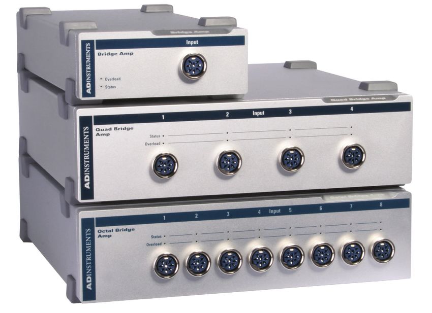
The Front Panel
The front panel of a Bridge Amp has a single socket for a transducer connection, a status
indicator light and an overload indicator light. The front panel of a Quad or Octal Bridge
Amp has four or eight transducer connections, respectively, each of which has a status
indicator light and an overload indicator light.
Figure 3–1
FE221 Bridge Amp
The front panels
of the Bridge
Amps
FE224 Quad Bridge Amp
FE228 Octal Bridge Amp
The Status Indicator
The Status indicator of the Bridge Amp is located at the bottom left of the front panel,
and the Status indicators of the Quad Bridge Amp and Octal Bridge Amp are located
adjacent to each connector on the front panel. When an ADInstruments program such
17 Owner’s Guideas LabChart starts up, the Status indicator light should glow green, indicating that the
program has found the front-end, checked and selected it, and is ready to use it. If the
light does not glow when the program is running, this indicates either that the front-end
is not connected properly or that there is a software or hardware problem.
The Input Socket
Transducers are connected to a Bridge Amp using the eight-pin DIN sockets on the
front panel. The sockets provide terminals for supplying a transducer with power and
for receiving the transducer output. Front-ends are supplied with DIN plug kits (one
per connection) to be fitted to those transducers that lack them. The connection is
discussed in more detail in the Technical section at the end of this chapter.
The Overload Indicator
The Overload indicator is located on the left side of the front panel of the Bridge Amp
and below the Status indicator on the Quad and Octal Bridge Amps.
The Overload indicator is normally off. If the indicator lights when a transducer is
attached, it indicates an out-of-compliance condition (meaning that the excitation
voltage drops because too much current is being drawn by the load). When the Bridge
Amp detects a problem with the transducer (for instance a wiring fault with a transducer
causing a short-circuit), the overload indicator will glow yellow or amber and will remain
on until the fault is rectified.
If the overload indicator remains on with a transducer attached, the transducer should
be removed immediately to minimize the risk of damage to the transducer. Check the
transducer wiring carefully before re-attaching the transducer. If the fault persists, refer
to the Troubleshooting section in this chapter.
For the overload indicator to function, power must be supplied to the Bridge Amp from
a PowerLab. LabChart software does not need to be loaded.
When a software application is running and a channel is being zeroed, the Status
indicators for the other channels should temporarily be off.
The Back Panel
The back panel of the Bridge Amp provides all the sockets required to connect the
Bridge Amp to the PowerLab and to other front-ends.
I2C Input and Output Sockets
Two nine-pin sockets are used to communicate with the PowerLab (they are marked ‘I2C
Bus’: a ‘bus’ is simply information-transmission circuitry such as cables and connectors).
These sockets allow multiple front-ends to be used independently with one PowerLab.
Power and control signals to the front-ends come from the PowerLab. Many front-ends
can be connected to the system, in series, output to input, providing there is the same
number of channel inputs available on the PowerLab (this is discussed in more detail in
Chapter 2).
18 Owner’s GuideFigure 3–2 FE221 Bridge Amp
The back panels
of the Bridge
Amps
FE224 Quad Bridge Amp
FE228 Octal Bridge Amp
Analog Output Sockets
BNC sockets on the back panel of the Bridge Amp provide the signal outputs to connect
to the analog input sockets on the front of the PowerLab. The sockets are labelled Signal
Output on a Bridge Amp and Output 1 to 4 or Output 1 to 8 on Quad and Octal Bridge
Amps, respectively. You don’t have to match the channel numbers when connecting
outputs to inputs, but it helps to prevent confusion if you do. A BNC-to-BNC cable is
supplied for each connection.
19 Owner’s GuideSetting Up
This section describes connecting a Bridge Amp to your PowerLab.
PowerLab Requirements
The FE221, FE224 and FE228 Bridge Amps will only operate with newer models of
PowerLabs, such as the /SP, /20, /25, /26, /30 and /35 series.
Software Requirements
The FE221, FE224 and FE228 Bridge Amps require the following versions of
ADInstruments software applications:
• LabChart version 6, or later, for Windows or Macintosh
• Chart version 5.4.2, or later, for Windows or Macintosh
• Scope for Windows version 3.7.8, or later
• Scope for Macintosh version 4.0.3, or later
• LabTutor version 3, or later.
Note: the Bridge Amps will not operate with earlier versions of these applications. If you
have queries regarding hardware and software requirements of the Bridge Amps, please
contact your local ADInstruments representative.
Connecting to the PowerLab
Connect your Bridge Amp, to the PowerLab, as follows:
• Ensure that the PowerLab is turned off. Failure to do this may damage the
PowerLab, the Bridge Amp, or both.
• Connect the I2C output of the PowerLab to the I2C input of the front-end using the
I2C cable provided.
• Connect a BNC cable from each signal output, on the rear of the Bridge Amp, to
an input on the front panel of the PowerLab.
Note that the Quad Bridge Amp acts just as if it were four individual Bridge Amps; the
Octal Bridge Amp, eight. The I2C connections are internal, though, so there is only one
I2C cable needed to connect the Quad or Octal Bridge Amps to the recording unit.
Check that the plugs for the I2C bus are screwed in firmly and the BNC cables have firm
connections. Loose connectors can cause erratic front-end behavior, or may cause the
front-end to fail to work at all. BNC cables can lie under the front-end to keep them out
of the way.
20 Owner’s GuideFigure 3–3 Bridge Amp Signal Output BNC connector cable
Connecting a
single Bridge Amp
front-end to the
PowerLab
Bridge Amp I2C input
PowerLab I2C output I2C connector cable
Multiple Front-ends
Multiple front-ends can be connected up to a PowerLab. The number that can be
connected depends on the number of analog inputs on the PowerLab. The initial front-
end should be connected as shown in Figure 6–3. The remainder are daisy-chained via
I2C cables, connecting the I2C output of the last connected front-end to the I2C input of
the next front-end to be added, as shown in Figure 2–2. The BNC cable for each front-end
is connected to one of the inputs of the PowerLab (except where otherwise specified).
Using LabChart
Once the Bridge Amp is connected, turn the PowerLab on and launch LabChart. While
the software starts up, keep a close eye on the Status and Overload indicators on the
Bridge Amp. During initialization, the Status indicators glow green, flash briefly, and
then remain lit.
If the indicator glows green, the Bridge Amp is working properly. If a light does not go
on when the program is started, this indicates either that the front-end is not connected
properly or that there is a software or hardware problem. If the overload light glows
yellow (or amber) on any Bridge Amp, this indicates some fault such as a short circuit,
a badly wired bridge transducer, or an excitation overload. In the first instance, check
your cable connections and transducers, and repeat the self-test. If this does not solve
the problem, contact your ADInstruments representative.
When a Bridge Amp is properly connected to the PowerLab, the Input Amplifier…
menu commands are replaced by Bridge Amp… for the input channel(s) to which
it is connected. If the application fails to find a front-end connected, the normal text
remains. If this occurs you should quit the application, turn the PowerLab off and check
the connections. Then restart the PowerLab and relaunch the application.
21 Owner’s GuideThe documentation for LabChart does not cover front-end-specific features. These
features are described in detail here for LabChart. For the most part, dialogs for
LabChart and Scope should be much the same.
The Bridge Amp dialog
The Bridge Amp dialog allows software control of the various amplifiers and filters in
the Bridge Amp and PowerLab for an input. The signal present at a PowerLab input is
displayed so that you can see the effects of changes straight away. Once the settings in
the dialog are changed, click OK to apply them.
To set up many channels quickly, open the Setup > Channel Settings... dialog. Here
you can view all the channels that are turned on, and you can turn off any unnecessary
channels. Clicking on Bridge Amp… in the Input Settings column of the Channel
Settings dialog will also open the Bridge Amp dialog.
Input selection Average signal value Pause/Scroll buttons
Figure 3–4
The Bridge
Amp dialog for
Windows (before
zeroing) Range pop-up
Set the offset for
the Bridge Amp
Filter options
Displays the Units Conversion Displays a voltmeter on screen for use
dialog when setting the offset externally
Signal Display
The input signal is displayed so you can see the effect of changing the settings — no
data are in fact recorded when setting things up. The average signal value is shown at
the top left of the display area.
You can stop the signal scrolling by clicking the Pause button at the bottom left
(Macintosh) or top right (Windows) of the data display area. On the Macintosh this
changes to the Scroll button. Click the Scroll button to start scrolling again.
22 Owner’s GuideYou can shift and stretch the vertical Amplitude axis by clicking and dragging it to make
the best use of the available display area. It functions the same as the Amplitude axis
of the Chart window; the controls are identical and any change is applied to the Chart
Window.
On a Macintosh, Show Range Axis in the Scale pop-up menu displays the range axis at
the right of the display area, and the Compression buttons adjust the horizontal axis of
the data display area.
Setting the Range
The Range pop-up menu lets you select the input range or sensitivity of the channel
(combined range of the PowerLab and Bridge Amp). Changing the range in the Bridge
Amp dialog is equivalent to changing it in the Chart window. The default setting is 5 V
and the ranges go down to 200 µV in 14 steps.
Filtering
The filtering options provided are appropriate to the type of transducers used with the
Bridge Amp, and the signals usually measured, which tend to be of lower frequency.
Low-pass filters allow you to remove high-frequency components, such as noise,
from an input signal. The Mains filter allows you to remove interference at the mains
frequency (typically 50 or 60 Hz).
Low-Pass Filtering. The Low Pass pop-up menu provides a choice of filters to remove
high-frequency components from the signal. They are: 1, 2, 10, 20, 100, and 200 Hz, and
1 kHz. (The highest frequency you can actually record is limited by the transducer you
use: such information should be in the documentation supplied with it.)
Mains Filter (/20, /25, /30 and /35 series PowerLabs). The Mains filter checkbox allows
you to filter out interference at the mains frequency (typically 50 or 60 Hz). Note that in
general it is better to prevent interference at its source than to filter it. The mains filter is
an adaptive filter which tracks the input signal over approximately 1 second. It analyzes
the signal and creates a template of any interference due to the mains frequency (see
“Specifications” on page 37). Subtraction of the template from the incoming signal
cancels most of the interference.
In comparison with a notch filter, this method produces little waveform distortion and
attenuates harmonics of the mains frequency as well as the fundamental; it effectively
removes non-sinusoidal interference, such as that commonly caused by fluorescent
lights.
The filter should not be used when:
• the interference changes rapidly. The filter takes about 1 second to adapt to
the present level. If interference is present, and then is suddenly removed,
interference in the filtered signal will temporarily be increased.
• your signal contains repetitive components at frequencies close to the mains
frequencies.
• your signal is already free from interference. If the signal-to-noise ratio is greater
than about 64 the mains filter introduces more noise than it removes.
23 Owner’s Guide• you are recording at close to maximum sampling rates. The mains filter uses
some of the PowerLab’s processing power and therefore reduces the maximum
rate at which you can sample.
The template is not fully generated until about 1 second after sampling starts and so the
mains filter is not fully effective in the first second of each data block.
Anti-alias
Click the Anti-alias checkbox to turn anti-aliasing on and off. Aliasing occurs when a
regular signal is digitized at too low a sampling rate, causing the false appearance of
lower frequency signals. To prevent aliasing, the sampling rate must be at least twice
the highest frequency in the incoming waveform.
When aliasing of noise or signals is seen, or even suspected, the first action you should
take is to increase the sampling rate. The highest available sampling rates are 100k
/s or 200k /s, depending on your PowerLab. If this reveals unwanted high-frequency
components in the sampled signal, you will achieve better results by using a low-pass
filter to remove them.
The best kind of filter for this purpose is the Anti-alias filter option in the Bridge Amp...
dialog. This is a special low-pass filter that is configured to automatically remove
all signals that could alias; i.e., those whose frequency is greater or equal to half the
sampling rate. A high sampling rate, however, will use more computer memory and
may limit recording time, so, once you have established the frequencies of interest to
you in an incoming signal, if Anti-alias is selected the sampling rate can be scaled down
accordingly.
Inverting the Signal
The Invert checkbox allows you to invert the signal on the screen. It provides a
simple way to change the polarity of the recorded signal without having to swap the
connections to the recording electrodes.
For example, you might be recording from a force transducer where an increase in force
downwards gives a negative signal, but you want to have a downwards force shown as
a positive signal on the screen. Checking the Invert checkbox will change the display to
do this.
Offset Adjustment
Transducers almost always produce some amount of signal, usually small, when in the
equilibrium or rest state. Offset from a zero reading need to be removed, in a process
called zeroing. Commonly, the user also wants to remove a constant term, for example
baseline blood pressure or initial tension in a muscle, from a measurement of interest.
This enables more accurate measurement of the changes in the signal under stimuli.
The offset controls in the Bridge Amp dialog can be used to zero the reading manually or
automatically.
Manual Zeroing. The up and down arrows near the Zero button allow manual
adjustment of the signal offset. Click the up arrow to shift the signal positively and the
24 Owner’s Guidedown arrow to shift it negatively. The shift by clicking the arrow buttons depends on the
range setting. At high ranges the increments are larger to adjust the offset efficiently.
Automatic Zeroing. To perform automatic zeroing, click Zero: the program works out
a corrective DC voltage that cancels, as closely as possible, the output voltage from
the transducer. Auto-zeroing may take about 20 seconds to work out the best zeroing
value at all ranges. A dialog with a progress bar appears: click the Cancel button or type
Command-period to stop the zeroing process. If there is still offset after auto-zeroing,
then Option-click the up and down arrow buttons to adjust the zeroing slightly, by the
smallest increment at any range.
Note: Variations in the transducer signal during the auto-zeroing operation will cause
the software to fail to zero the offset properly, if it zeroes at all. Make sure that the
transducer is kept still and that no varying signal is applied during the operation.
The offset display, a small numeric indicator above the Zero button, shows the
corrective voltage used to adjust for transducer offset. The offset is given in the units
of the channel. When the Bridge Amp is first powered up, the software sets the offset
circuit to its default position (no offset adjustment of the transducer) and the offset
display value is zero. When either Zero or the manual offset controls are clicked, this
value will change to indicate the positive or negative corrective adjustment.
On a Macintosh, click the small 0 button to restore the offset circuit to its initial, non-
zeroed position (and the offset display value to zero). This can be used to determine the
offset generated by a transducer.
Display Offset
Click Display Offset… to display the Input Value dialog, which is a voltmeter displaying
the voltage currently being measured for an input (the input channel is indicated at
the top of the dialog). If a transducer or some other external equipment has offset
adjustment capabilities, you can use this to zero it.
Figure 3–5
The Input Value
dialog, Windows
(left) and
Macintosh (right)
25 Owner’s GuideBecause the dialog allows for such fine adjustment, a vertical arrow appears indicating
the zero point if the offset is substantial. This dialog is not a control, simply an indicator
that acts like a voltmeter.
Units
Click Units… to display the Units Conversion dialog, in which you specify the units for
the channel and calibrate the channel. The waveform in the display area of the Bridge
Amp dialog is transferred to the data display area of the Units Conversion dialog. (Use
the Pause button to capture a specific signal.) The units conversion only applies to
subsequently recorded signals, so it is more limited than choosing Units Conversion…
from a Channel Function pop-up menu, which allows units conversion of previously
recorded data.
Using Transducers
Bridge Amps are designed to allow the PowerLab to connect to most DC bridge
transducers, including commonly-available force, pressure, and displacement
transducers, temperature probes, light meters, and similar devices. They are capable
of supporting various powered transducers, and certain low-impedance unpowered
(or self-powered) transducers. However, because transducers vary in sensitivity and
suitability, you should read the following sections before connecting a transducer to a
Bridge Amp.
The ‘Adapting Transducers’ section describes the modifications that may be required
to connect third-party transducers to the Bridge Amp. Transducers supplied by
ADInstruments should connect directly without modification, so if using these you need
not read this section. If you are using powered third-party transducers with your Bridge
Amp you may need to adapt them using the information provided in this later section.
NOTE: Please ensure that any modifications made to transducers are carried out
by experienced technical staff. Some soldering of components is required to adapt
third-party transducers for use with your Bridge Amp. Incorrect wiring may damage
the transducer or Bridge Amp. If you have little experience with electronics and no
technician to assist you, please contact your nearest ADInstruments representative for
further assistance.
Compatibility
Transducers supplied by ADInstruments will operate with the FE22x Bridge Amps. All
transducers which operated with the older model ML110, ML112, ML118, ML119 Bridge
Amps will operate with the FE22x Bridge Amps. The ML110 and ML112 amplifiers had
provision for increasing offsetting resolution via an optional resistor installed in the
transducer connector. Transducers which have this offsetting resistor fitted will operate
with the FE22x Bridge Amps without modification.
26 Owner’s GuideSuitable Transducers
The Bridge Amps are designed to connect to transducers that require DC excitation
voltages, such as DC strain-gauge or semiconductor transducers.
If you are uncertain about the suitability of your transducer, please provide
ADInstruments with an accurate circuit of the transducer and a sample, and we will see
about testing the device for compatibility. Half-bridge transducers will need to be wired
up with compensating resistors before they can be used with any of the Bridge Amps
(see Technical Aspects section).
DC Strain-gauge. These are full-bridge or half-bridge transducers requiring a DC
excitation voltage, and output voltages of less than 200 mV full scale. They include
strain-gauge force transducers, temperature transducers and pressure transducers.
Semiconductor. These are powered transducers typically used for light, displacement,
and temperature measurements, giving output voltages less than 200 mV full scale.
Generally, a Bridge Amp can be used with transducers that:
• require DC excitation voltages, not AC
• have transducer output voltages less than 5 V full scale
• have transducer impedances less than 10 kΩ.
Unsuitable Transducers
Some transducers are not supported and should not be used with the Bridge Amp.
These include LVDT, capacitive bridge, piezoelectric and high-voltage transducers.
LVDT (linear variable differential transformer). This type of transducer requires AC
excitation voltages. The Bridge Amp is for use with transducers requiring DC excitation.
Connecting an LVDT transducer to the Bridge Amp may damage the transducer.
Capacitive Bridge. These transducers require AC excitation. The Bridge Amp is for use
with transducers requiring DC excitation.
Piezoelectric. These transducers are not recommended owing to the relatively
low input impedance of the single Bridge Amp (piezoelectric transducers typically
need amplifiers with input impedances of tens of megaohms), and their half-bridge
configuration.
High-voltage. Transducers generating more than ± 5 V full scale will exceed the input
range of the Bridge Amp. A high-voltage powered transducer may require some signal
attenuation.
How Transducers Work
The Bridge Amp can connect to most bridge-type transducers, hence its name. The term
‘bridge’ refers to the circuit configuration that is normally called a Wheatstone bridge.
These transducers come in two forms: full-bridge and half-bridge. Some explanation
is given here of bridge-type transducers, although there are of course other types that
work differently, such as the semiconductor transducer.
27 Owner’s GuideYou can also read