Pololu 3pi Robot User's Guide - Pololu 3pi Robot User's Guide
←
→
Page content transcription
If your browser does not render page correctly, please read the page content below
Pololu 3pi Robot User’s Guide          © 2001–2019 Pololu Corporation

   Pololu 3pi Robot User’s Guide

https://www.pololu.com/docs/0J21/all                     Page 1 of 85
Pololu 3pi Robot User’s Guide                                                               © 2001–2019 Pololu Corporation

  1. Introduction . . . . . . . . . . . . . . . . . . . . . .   .   .   .   .   .   .   .   .   .   .   .   .   .   .   .   .   .   .   .   .   .   .   . 3
  2. Contacting Pololu . . . . . . . . . . . . . . . . . . .    .   .   .   .   .   .   .   .   .   .   .   .   .   .   .   .   .   .   .   .   .   .   . 4
  3. Important Safety Warning and Handling Precautions          .   .   .   .   .   .   .   .   .   .   .   .   .   .   .   .   .   .   .   .   .   .   . 5
  4. Getting Started with Your 3pi Robot . . . . . . . . .      .   .   .   .   .   .   .   .   .   .   .   .   .   .   .   .   .   .   .   .   .   .   . 6
       4.a. What You Will Need . . . . . . . . . . . . . .      .   .   .   .   .   .   .   .   .   .   .   .   .   .   .   .   .   .   .   .   .   .   . 7
       4.b. Powering Up Your 3pi . . . . . . . . . . . . .      .   .   .   .   .   .   .   .   .   .   .   .   .   .   .   .   .   .   .   .   .   .   . 8
       4.c. Using the Preloaded Demo Program . . . . .          .   .   .   .   .   .   .   .   .   .   .   .   .   .   .   .   .   .   .   .   .   .   . 8
       4.d. Included Accessories . . . . . . . . . . . . .      .   .   .   .   .   .   .   .   .   .   .   .   .   .   .   .   .   .   .   .   .   .    10
  5. How Your 3pi Works . . . . . . . . . . . . . . . . .       .   .   .   .   .   .   .   .   .   .   .   .   .   .   .   .   .   .   .   .   .   .    11
       5.a. Batteries . . . . . . . . . . . . . . . . . . . .   .   .   .   .   .   .   .   .   .   .   .   .   .   .   .   .   .   .   .   .   .   .    11
       5.b. Power management . . . . . . . . . . . . . .        .   .   .   .   .   .   .   .   .   .   .   .   .   .   .   .   .   .   .   .   .   .    13
       5.c. Motors and Gearboxes . . . . . . . . . . . .        .   .   .   .   .   .   .   .   .   .   .   .   .   .   .   .   .   .   .   .   .   .    15
       5.d. Digital inputs and sensors . . . . . . . . . . .    .   .   .   .   .   .   .   .   .   .   .   .   .   .   .   .   .   .   .   .   .   .    20
       5.e. 3pi Simplified Schematic Diagram . . . . . . .      .   .   .   .   .   .   .   .   .   .   .   .   .   .   .   .   .   .   .   .   .   .    23
  6. Programming Your 3pi . . . . . . . . . . . . . . . .       .   .   .   .   .   .   .   .   .   .   .   .   .   .   .   .   .   .   .   .   .   .    26
  7. Example Project #1: Line Following . . . . . . . . .       .   .   .   .   .   .   .   .   .   .   .   .   .   .   .   .   .   .   .   .   .   .    27
       7.a. About Line Following . . . . . . . . . . . . .      .   .   .   .   .   .   .   .   .   .   .   .   .   .   .   .   .   .   .   .   .   .    27
       7.b. A Simple Line-Following Algorithm for 3pi . . .     .   .   .   .   .   .   .   .   .   .   .   .   .   .   .   .   .   .   .   .   .   .    27
       7.c. Advanced Line Following with 3pi: PID Control       .   .   .   .   .   .   .   .   .   .   .   .   .   .   .   .   .   .   .   .   .   .    35
  8. Example Project #2: Maze Solving . . . . . . . . . .       .   .   .   .   .   .   .   .   .   .   .   .   .   .   .   .   .   .   .   .   .   .    37
       8.a. Solving a Line Maze . . . . . . . . . . . . . .     .   .   .   .   .   .   .   .   .   .   .   .   .   .   .   .   .   .   .   .   .   .    37
       8.b. Working with Multiple C Files in Atmel Studio .     .   .   .   .   .   .   .   .   .   .   .   .   .   .   .   .   .   .   .   .   .   .    37
       8.c. Left Hand on the Wall . . . . . . . . . . . . .     .   .   .   .   .   .   .   .   .   .   .   .   .   .   .   .   .   .   .   .   .   .    41
       8.d. The Main Loop(s) . . . . . . . . . . . . . . .      .   .   .   .   .   .   .   .   .   .   .   .   .   .   .   .   .   .   .   .   .   .    42
       8.e. Simplifying the Solution . . . . . . . . . . . .    .   .   .   .   .   .   .   .   .   .   .   .   .   .   .   .   .   .   .   .   .   .    44
       8.f. Improving the Maze-Solving Code . . . . . . .       .   .   .   .   .   .   .   .   .   .   .   .   .   .   .   .   .   .   .   .   .   .    51
  9. Pin Assignment Tables . . . . . . . . . . . . . . . .      .   .   .   .   .   .   .   .   .   .   .   .   .   .   .   .   .   .   .   .   .   .    54
  10. Expansion Information . . . . . . . . . . . . . . .       .   .   .   .   .   .   .   .   .   .   .   .   .   .   .   .   .   .   .   .   .   .    61
       10.a. Serial slave program . . . . . . . . . . . . .     .   .   .   .   .   .   .   .   .   .   .   .   .   .   .   .   .   .   .   .   .   .    61
       10.b. Serial master program . . . . . . . . . . . .      .   .   .   .   .   .   .   .   .   .   .   .   .   .   .   .   .   .   .   .   .   .    75
       10.c. Available I/O on the 3pi's ATmegaxx8 . . . .       .   .   .   .   .   .   .   .   .   .   .   .   .   .   .   .   .   .   .   .   .   .    82
  11. Related Resources . . . . . . . . . . . . . . . . .       .   .   .   .   .   .   .   .   .   .   .   .   .   .   .   .   .   .   .   .   .   .    84
  12. Revision History and Errata . . . . . . . . . . . . .     .   .   .   .   .   .   .   .   .   .   .   .   .   .   .   .   .   .   .   .   .   .    85

                                                                                                                                        Page 2 of 85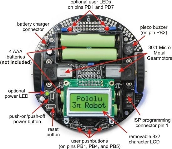
Pololu 3pi Robot User’s Guide                                             © 2001–2019 Pololu Corporation

  1. Introduction

           Note: Starting with serial number 0J5840, 3pi robots are shipping with the newer
           ATmega328P microcontroller instead of the ATmega168. The serial number is located
           on a white bar code sticker on the bottom of the 3pi PCB. The ATmega328 is essentially
           a drop-in replacement for the ATmega168 with twice the memory (32 KB flash, 2 KB
           RAM, and 1 KB of EEPROM), so the 3pi code written for the ATmega168 should
           work with minimal modification on the ATmega328 (the Pololu AVR Library
           [https://www.pololu.com/docs/0J20] now supports the ATmega328P).

  The Pololu 3pi robot is a small, high-performance, autonomous robot designed to excel in line-
  following and line-maze-solving competitions. Powered by four AAA batteries (not included) and a
  unique power system that runs the motors at a regulated 9.25 V, 3pi is capable of speeds up to 100
  cm/second while making precise turns and spins that don’t vary with the battery voltage. This results
  in highly consistent and repeatable performance of well-tuned code even as the batteries run low.
  The robot comes fully assembled with two micro metal gearmotors, five reflectance sensors, an 8×2
  character LCD, a buzzer, three user pushbuttons, and more, all connected to a user-programmable
  AVR microcontroller. The 3pi measures approximately 3.7 inches (9.5 cm) in diameter and weighs 2.9
  oz (83 g) without batteries.

  The 3pi is based on an Atmel ATmega168 or ATmega328 microcontroller, henceforth referred to as
  the “ATmegaxx8”, running at 20 MHz. ATmega168-based 3pi robots feature 16 KB of flash program
  memory and 1 KB RAM, and 512 bytes of persistent EEPROM memory; ATmega328-based 3pi robots
  feature 32 KB of flash program memory, 2 KB RAM, and 1 KB of persistent EEPROM memory.
  The use of the ATmegaxx8 microcontroller makes the 3pi compatible with the popular Arduino
  development platform. Free C and C++ development tools are also available, and an extensive set
  of libraries make it a breeze to interface with all of the integrated hardware. Sample programs are
  available to show how to use the various 3pi components, as well as how to perform more complex
  behaviors such as line following and maze solving.

  Please note that an external AVR ISP programmer, such as our USB AVR Programmer v2.1
  [https://www.pololu.com/product/3172] is required to program the 3pi robot.

           For a Spanish version of this document, please see Pololu 3pi Robot Guia Usuario
           [https://www.pololu.com/file/0J137/Pololu3piRobotGuiaDeUsuario.pdf] (3MB pdf) (provided by
           customer Jaume B.).

1. Introduction                                                                               Page 3 of 85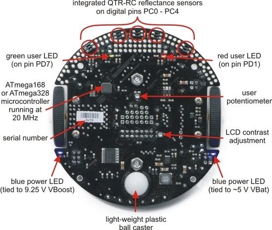
Pololu 3pi Robot User’s Guide                                                     © 2001–2019 Pololu Corporation

  2. Contacting Pololu
  You can check the 3pi product page              [https://www.pololu.com/product/975]   for additional information,
  including pictures, videos, example code, and other resources.

  We would be delighted to hear from you about any of your projects and about your experience
  with the 3pi robot. You can contact us [https://www.pololu.com/contact] directly or post on our forum
  [http://forum.pololu.com/].   Tell us what we did well, what we could improve, what you would like to see in
  the future, or share your code with other 3pi users.

2. Contacting Pololu                                                                                     Page 4 of 85
Pololu 3pi Robot User’s Guide                                             © 2001–2019 Pololu Corporation

  3. Important Safety Warning and Handling Precautions
  The 3pi robot is not intended for young children! Younger users should use this product only under
  adult supervision. By using this product, you agree not to hold Pololu liable for any injury or damage
  related to the use or to the performance of this product. This product is not designed for, and should
  not be used in, applications where the malfunction of the product could cause injury or damage. Please
  take note of these additional precautions:

      • Do not attempt to program your 3pi if its batteries are drained or uncharged. Losing power
        during programming could permanently disable your 3pi. If you have purchased
        rechargeable batteries for use with the 3pi, do not assume they come fully charged; charge
        them before you first use them. The 3pi has the ability to monitor its battery voltage; the
        example line-following and maze-solving programs we provide show how to use this feature,
        and you should include it in your programs so you can know when its time to recharge or
        replace your batteries.

      • The 3pi robot is intended for use indoors on relatively flat, smooth surfaces. Avoid running
        your 3pi on surfaces that might scrape or damage the underside of your robot’s PCB as it
        drives around.

      • Avoid placing the robot so that the underside of the PCB makes contact with conductive
        materials (e.g. do not place the 3pi in a bin filled with metal parts). This could inadvertently
        short out the batteries and damage your robot, even with the 3pi turned off. Shorting various
        pads or components together could also damage your 3pi.

      • Since the PCB and its components are exposed, take standard precautions to protect your
        3pi robot from ESD (electrostatic discharge), which could damage the on-board electronics.
        When picking up the 3pi, you should first touch a safe part of the robot such as the wheels,
        motors, batteries, or the edges of the PCB. If you first touch components on the PCB, you
        risk discharging through them. When handing the 3pi to another person, first touch their hand
        with your hand to equalize any charge imbalance between you so that you don’t discharge
        through the 3pi as the exchange is made.

      • If you remove the LCD, take care to replace it in the right orientation such that it is over the
        rear battery back. It is possible to put the LCD in backwards or offset; doing so could damage
        the LCD or the 3pi.

3. Important Safety Warning and Handling Precautions                                           Page 5 of 85
Pololu 3pi Robot User’s Guide © 2001–2019 Pololu Corporation
4. Getting Started with Your 3pi Robot
Getting started with your 3pi can be as simple as taking it out of the box, adding batteries, and turning
it on. The 3pi ships with a demo program that will give you a brief tour of its features.
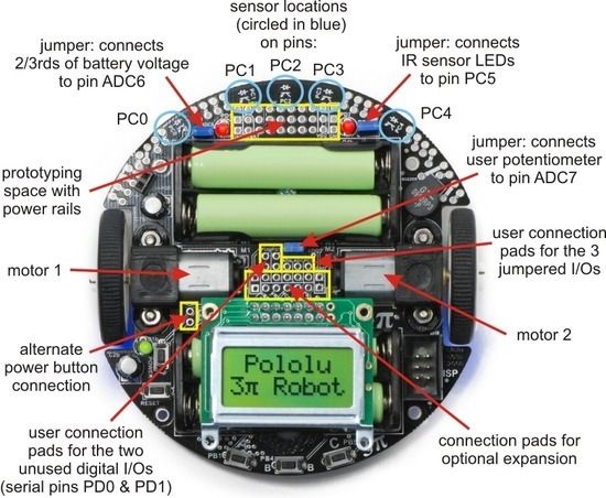
General features of the Pololu 3pi robot, top view.
4. Getting Started with Your 3pi Robot Page 6 of 85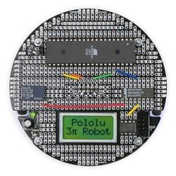
Pololu 3pi Robot User’s Guide                                                © 2001–2019 Pololu Corporation

                              Labeled bottom view of the Pololu 3pi robot.

  The following subsections will give you all the information you need to get your 3pi up and running!

  4.a. What You Will Need
  The following materials are necessary for getting started with your 3pi:

      • 4 AAA batteries. Any AAA cells will work, but we recommend NiMH batteries, which are
        rechargeable and can be purchased from Pololu [https://www.pololu.com/product/1002] or at a
         local store. If you use rechargeable batteries, you will also need a battery charger. Battery
         chargers designed to connect to external series battery packs, such as the iMAX-B6AC
         [https://www.pololu.com/product/2588], may be used with the 3pi’s battery charger port.

      • AVR ISP programmer with 6-pin connector. The 3pi features an ATmega328P
        microcontroller, which requires an external programmer such as the Pololu USB AVR
        Programmer v2.1 [https://www.pololu.com/product/3172] or Atmel’s AVRISP series. The 3pi has

4. Getting Started with Your 3pi Robot                                                         Page 7 of 85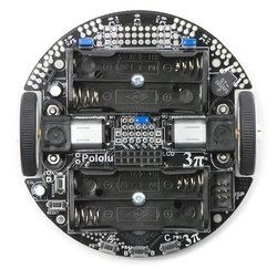
Pololu 3pi Robot User’s Guide © 2001–2019 Pololu Corporation
a standard 6-pin programming connector, so your programmer will need to have a 6-pin ISP
cable [https://www.pololu.com/product/972] for connecting to the target device. (You will also need
whatever cable your programmer requires to connect to a computer.
• A desktop or laptop computer. You will need a personal computer for developing your
code and loading it onto the 3pi. The 3pi can be programmed on Windows, Mac, and Linux
operating systems, but Pololu support for Macs is limited.
You might find the following materials useful in creating an environment for your robot to explore:
• Several large sheets of white posterboard (available at crafts or office supply stores) or dry-
erase whiteboard stock (commonly available at home/construction supply stores).
• Light-colored masking tape for joining multiple sheets together.
• 3/4" black electrical tape to create lines for your robot to follow.
4.b. Powering Up Your 3pi
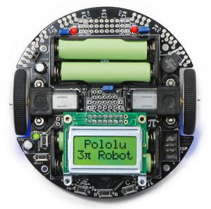
The first step in using your new 3pi robot is to insert four
AAA batteries into the battery holders. To do this you will
need to remove the LCD. Pay attention to the LCD’s
orientation as you will want to plug it back in this way
when you are done. With the LCD removed your 3pi
should look like the picture to the right.
Once the batteries are in place, you should return the
LCD to its position over the rear battery holder. Make
sure each male LCD header pin goes into a
corresponding female socket.
Next, push the power button (located on the left side of
the rear battery pack) to turn on your 3pi. You should see
the two blue power LEDs on the underside of the 3pi light, and the 3pi should begin running its
preloaded demo program. You can simply push the power button again to turn the 3pi off, and you can
push the reset button (located just below the power button) to reset the program the robot is running.
4.c. Using the Preloaded Demo Program
Your 3pi comes preloaded with a program that demonstrates most of its features and allows you to
test that it is working correctly. When you first turn on your 3pi, you will hear a beep and see the
words “Pololu 3pi Robot”, then “Demo Program” appear, indicating that you are running the demo
program. If you hear a beep but do not see any text on the LCD, you may need to adjust the contrast
4. Getting Started with Your 3pi Robot Page 8 of 85
Pololu 3pi Robot User’s Guide                                             © 2001–2019 Pololu Corporation

  potentiometer on the underside of the board. When the program has started successfully, press the
  B button to proceed to the main menu. Press C or A to scroll forward or backward through the menu,
  and press B to make a selection or to exit one of the demos. There are seven demos accessible from
  the menu:

     1. Battery: This demo displays the battery voltage in millivolts, which should be above 5000
        (5.0 Volts) for a fully-charged set of batteries. Removing the jumper marked ADC6 will
        separate the battery voltage measurement circuit from the analog input, causing the number
        displayed to drop to some low value.

     2. LEDs: Blinks the red and green user LEDs on the underside of the board. If you have
        soldered in the optional user LEDs, they will also blink.

     3. Trimpot: Displays the position of the user trimmer potentiometer, which is located on the
        underside of the board, as a number between 0 and 1023. While displaying the value, this
        demo also blinks the LEDs and plays a note whose frequency is a function of the current
        reading. It is easiest to turn the trimpot using a 2mm flat-head screwdriver.

     4. Sensors: Show the current readings of the IR sensors using a bar graph. Bigger bars mean
        lower reflectance. Placing a reflective object such as your finger under one of the sensors will
        cause the corresponding reading to drop visibly on the graph. This demo also displays “C” to
        indicate that button C has an effect—press C and the IR emitters will be turned off. In indoor
        lighting conditions away from bright incandescent or halogen lights, all of the sensors should
        return entirely black readings with IR off. Removing the jumper marked PC5 disables control
        of the emitters, causing them to always be on.

     5. Motors: Hold down A or C to run the motor on the corresponding side, or hold down both
        buttons to run both motors simultaneously. The motors will gradually ramp up to speed; in
        your own programs, you can switch them on much more suddenly. Tap A or C to switch the
        corresponding motor to reverse (the button letter becomes lowercase if pressing it will drive
        the corresponding motor in reverse).

     6. Music: Plays an adaptation of J. S. Bach’s Fugue in D Minor for microcontroller and piezo,
        while scrolling a text display. This demonstrates the ability of the 3pi to play music in the
        background.

     7. Timer: A simple stopwatch. Press C to start or stop the stopwatch and A to reset. The
        stopwatch continues to count while you are exploring the other demos.

           Note: If the 3pi receives any serial data while the demo program is waiting for a button
           press from the user, it will switch into serial slave mode. See Section 10.a for more
           information.

4. Getting Started with Your 3pi Robot                                                         Page 9 of 85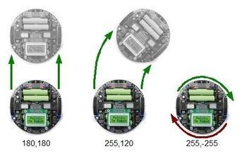
Pololu 3pi Robot User’s Guide                                            © 2001–2019 Pololu Corporation

  The source code for the demo program is included with the Pololu AVR C/C++ Library described in
  Section 6, in the folder examples\atmega328p\3pi-demo-program .

  4.d. Included Accessories

  The 3pi robot ships with two through-hole red LEDs and
  two through-hole green LEDs. There are connection
  points for three optional LEDs on your 3pi: one next to
  the power button to indicate when the 3pi is on and two
  user-controllable LED ports near the front edge of the
  robot. Using these LEDs is completely optional as the 3pi
  will function just fine without them. You can customize
  your 3pi by choosing your desired combination of red and
  green LEDs, or you can even use your own LEDs
  [https://www.pololu.com/category/20/leds] if you want more
  color/brightness options.

  Note that you should only add LEDs if you are comfortable soldering, and you should take care to
  avoid desoldering any of the components near the through-hole LED pads. LEDs are polarized, so be
  sure to solder them such that the longer lead connects to the pad marked with the +. Before you solder
  them in you can press-fit them in place and check to make sure they light as expected. Once soldered
  in place, carefully trim off the excess portion of the LED leads.

  Your 3pi also ships with three shorting blocks of each color: blue, red, yellow, black. This means you
  can customize your 3pi by selecting the shorting block color you most prefer, or you can use a mixture
  of colors!

4. Getting Started with Your 3pi Robot                                                      Page 10 of 85
Pololu 3pi Robot User’s Guide                                              © 2001–2019 Pololu Corporation

  5. How Your 3pi Works
  5.a. Batteries
  Introduction to Batteries

  The power system on the 3pi begins with the batteries, so it is
  important to understand how your batteries work. A battery
  contains a carefully controlled chemical reaction that pulls
  electrons in from the positive (+) terminal and pushes them out of
  the negative (-) terminal. The most common type is the alkaline
  battery, which is based on a reaction between zinc and
  manganese through a potassium hydroxide solution. Once
  alkaline batteries are completely discharged, they cannot be
  reused. For the 3pi, we recommend rechargeable nickel-metal-
  hydride (NiMH) batteries, which can be recharged over and over.         Two rechargeable AAA Ni-MH
                                                                                    batteries.
  NiMH batteries are based on a different chemical reaction from
  alkaline batteries, but you don’t need to know anything about the
  chemical details to use a battery: everything you need to know about it is measured with a few simple
  numbers. The first is the strength with which the electrons are pushed, which we measure in volts (V),
  the units of electric potential. An NiMH battery has a voltage of about 1.2 V. To understand how much
  power you can get out of a battery, you also need to know how many electrons the battery can push
  per second – this is the electric current, measured in amps (A). A current of 1 A corresponds to about
  6×10¹⁸ electrons flowing out one side and in to the other each second, which is such a huge number
  that it’s easier to talk about it just in terms of amps. 1 A is also a typical current that a medium-sized
  motor might use, and it’s a current that will put a significant strain on small (AAA) batteries.

  For any battery, if you attempt to draw more and more current, the voltage produced by the battery will
  drop, eventually dropping all the way to zero at the short circuit current: the current that flows if you
  connect one side directly to the other with a thick wire. (Don’t try this! The wire might overheat and
  melt, and the battery could explode.) The following graph shows a good model of how the voltage on
  a typical battery drops as the current goes up:

5. How Your 3pi Works                                                                          Page 11 of 85
Pololu 3pi Robot User’s Guide © 2001–2019 Pololu Corporation
Battery voltage vs. current.
The power put out by a battery is measured by multiplying the volts by the amps, giving a
measurement in watts (W). For example, at the point marked in the graph, we have a voltage of
0.9 V and a current of 0.6 A, this means that the power output is 0.54 W. If you want more power,
you need to add more batteries, and there are two ways to do it: parallel and series configurations.
When batteries are connected in parallel, with all of their positive terminals tied together and all of
their negative terminals tied together, the voltage stays the same, but the maximum current output is
multiplied by the number of batteries. When they are connected in series, with the positive terminal
of one connected to the negative terminal of the next, the maximum current stays the same while the
voltage multiplies. Either way, the maximum power output will be multiplied by the number of batteries.
Think about two people using two buckets to lift water from a lake to higher ground. If they stand next
to each other (working in parallel), they will be able to lift the water to the same height as before, while
delivering twice the amount of water. If one of them stands uphill from the other, they can work together
(in series) to lift the water twice as high, but at the same rate as a single person.
In practice, we only connect batteries in series. This is because different batteries will always have
slightly different voltages, and if they are connected in parallel, the stronger battery will deliver current
to the weaker battery, wasting power even when there is nothing else in the circuit. If we want more
current, we can use bigger batteries: AAA, AA, C, and D batteries of the same type all have the same
voltage, but they can put out very different amounts of current.
The total amount of energy in any battery is limited by the chemical reaction: once the chemicals are
exhausted, the battery will stop producing power. This happens gradually: the voltage and current
produced by a battery will steadily drop until the energy runs out, as shown in the graph below:
5. How Your 3pi Works Page 12 of 85Pololu 3pi Robot User’s Guide © 2001–2019 Pololu Corporation
Battery voltage vs. time.
A rough measure of the amount of energy stored in a battery is given by its milliamp-hour (mAH)
rating, which specifies how long the battery will last at a given discharge rate. The mAH rating is the
discharge rate multiplied by how long the battery lasts: if you draw current at a rate of 200 mA (0.2 A),
and the battery lasts for 3 hours, you would call it a 600 mAH battery. If you discharge the same battery
at 600 mA, you would get about an hour of operation (however, battery capacity tends to decline with
faster discharge rates, so you might only get 50 minutes).
Note: If you have purchased rechargeable batteries for the 3pi, you should fully charge
them before you first use them. You should never attempt to program your 3pi if
its batteries are drained or uncharged. Losing power during programming could
permanently disable your 3pi.
5.b. Power management
Battery voltage drops as the batteries are used up, but many electrical components require a specific
voltage. A special kind of component called a voltage regulator helps out by converting the battery
voltage to a constant, specified voltage. For a long time, 5 V has been the most common regulated
voltage used in digital electronics; this is also called TTL level. The microcontroller and most of the
circuitry in the 3pi operate at 5 V, so voltage regulation is essential. There are two basic types of
voltage regulators:
• Linear regulators use a simple feedback circuit to vary how much energy is passed through
and how much is discarded. The regulator produces a lower output voltage by dumping
unneeded energy. This wasteful, inefficient approach makes linear regulators poor choices
for applications that have a large difference between the input and output voltages, or for
5. How Your 3pi Works Page 13 of 85Pololu 3pi Robot User’s Guide © 2001–2019 Pololu Corporation
applications that require a lot of current. For example, 15 V batteries regulated down to 5 V
with a linear regulator will lose two-thirds of their energy in the linear regulator. This energy
becomes heat, so linear regulators often need large heat sinks, and they generally don’t work
well with high-power applications.
• Switching regulators turn power on and off at a high frequency, filtering the output to
produce a stable supply at the desired voltage. By carefully redirecting the flow of electricity,
switching regulators can be much more efficient than linear regulators, especially for high-
current applications and large changes in voltage. Also, switching regulators can convert low
voltages into higher voltages! A key component of a switching regulator is the inductor, which
stores energy and smooths out current; on the 3pi, the inductor is the gray block near the ball
caster labeled “100”. A desktop computer power supply also uses switching regulators: peek
through the vent in the back of your computer and look for a donut-shaped piece with a coil
of thick copper wire wrapped around it – that’s the inductor.
The power management subsystem built into the 3pi is shown in this block diagram:
The voltage of 4 x AAA cells can vary between 3.5 – 5.5 V (and even to 6 V if alkalines are used).
This means it’s not possible simply to regulate the voltage up or down to get 5 V. Instead, in the
3pi, a switching regulator first boosts the battery voltage up to 9.25 V (Vboost), and a linear regulator
regulates Vboost back down to 5 V (VCC). Vboost powers the motors and the IR LEDs in the line
sensors, while VCC is used for the microcontroller and all digital signals.
Using Vboost for the motors and sensors gives the 3pi three unique performance advantages over
typical robots, which use battery power directly:
• First, a higher voltage means more power for the motors, without requiring more current and
5. How Your 3pi Works Page 14 of 85Pololu 3pi Robot User’s Guide © 2001–2019 Pololu Corporation
a larger motor driver.
• Second, since the voltage is regulated, the motors will run the same speed as the batteries
drop from 5.5 down to 3.5 V. You can take advantage of this when programming your 3pi, for
example by calibrating a 90° turn based on the amount of time that it takes.
• Third, at 9.25 V, all five of the IR LEDs can be powered in series so that they consume the
lowest possible amount of power. (Note that you can switch the LEDs on and off to save even
more power.)
One other interesting thing about this power system is that instead of gradually running out of power
like most robots, the 3pi will operate at maximum performance until it suddenly shuts off. This can take
you by surprise, so you might want your 3pi to monitor its battery voltage.
A simple circuit for monitoring battery voltage is built in to the 3pi.
Three resistors, shown in the circuit at right, comprise a voltage
divider that outputs a voltage equal to two-thirds of the battery
voltage, which will always be safely below the main microcontroller’s
maximum analog input voltage of 5 V. For example, at a battery
voltage of 4.8 V, the battery voltage monitor port ADC6 will be at a
level of 3.2 V. Using 10-bit analog-to-digital conversion, where 5 V is
read as a value of 1023, 3.2 V is read as a value of 655. To convert
it back to the actual battery voltage, multiply this number by
5000 mV×3/2 and divide by 1023. This is handled conveniently by
the read_battery_millivolts_3pi() function (provided in the Pololu
AVR Library; see Section 6 for more information), which averages ten samples and returns the battery
voltage in mV:
1 unsigned int read_battery_millivolts_3pi() ?
2 {
3 return readAverage(6,10)*5000L*3/2/1023;
4 }
5.c. Motors and Gearboxes
5. How Your 3pi Works Page 15 of 85Pololu 3pi Robot User’s Guide © 2001–2019 Pololu Corporation
A motor is a machine that converts electrical energy to motion.
There are many different kinds of motors, but the most important
for low-cost robotics is the brushed DC motor, which is the type
used on the 3pi. A brushed DC motor typically has permanent
magnets on the outside and several electromagnetic coils
mounted on the motor shaft (armature). The “brushes” are sliding
pieces of metal that switch the power from one coil to the next as
the shaft turns so that magnetic attraction between the coil and
the magnets continuously pulls the motor in the same direction.
A typical small brushed DC
motor, with no gearbox.
The primary values that describe a running motor are its speed,
measured in rpm, and its torque, measured in kg·cm or oz·in
(pronounced “ounce-inches”). The units for torque show the dependence on both force and distance;
for example, a motor that produces 6 oz·in of torque can product a force of 6 oz. with a 1-inch lever
arm, 3 oz. with a 2-inch lever, and so on. Multiplying the torque and speed (measured at the same
time) give us the power delivered by a motor. We see, therefore, that a motor with twice the speed and
half the torque as another has the same power output.
Every motor has a maximum speed (when no force is applied) and a maximum torque (when the motor
is completely stopped). We call these the free-running speed and the stall torque. Naturally, a motor
uses the least current when no force is applied to it, and the current drawn from the batteries goes up
until it stalls, so the free-running current and stall current are also important parameters characterizing
the motor. The stall current is usually much higher than the free-running current, as shown in the graph
below:
Motor operation: current and speed vs. torque.
5. How Your 3pi Works Page 16 of 85Pololu 3pi Robot User’s Guide © 2001–2019 Pololu Corporation
The free-running speed of a small DC motor is usually many
thousands of rotations per minute (rpm), much higher than the
speed we want the wheels of a robot to turn. A gearbox is a
system of gears that converts the high-speed, low-torque output
of the motor into a lower-speed, higher-torque output that is a
much better suited for driving a robot. The gear ratio used on the
3pi is 30:1, which means that for every 30 turns of the motor shaft,
the output shaft turns once. This reduces the speed by a factor of
30, and (ideally) increases the torque by a factor of 30. The
The 30:1 gearmotor used on the
resulting parameters of the 3pi motors are summarized in this 3pi.
table:
Gear ratio: 30:1
Free-running speed: 700 rpm
Free-running current: 60 mA
Stall torque: 6 oz·in
Stall current: 540 mA
The two wheels of the 3pi each have a radius of 0.67 in, which means that the maximum force it can
produce with two motors when driving forward is 2×6/0.67 = 18 oz. The 3pi weighs about 7 oz with
batteries, so the motors are strong enough to lift the 3pi up a vertical slope or accelerate it at 2 g (twice
the acceleration of gravity). The actual performance is limited by the friction of the tires: on a steep
enough slope, the wheels will slip before they stall – in practice, this happens when the slope is around
30-40°.
Driving a motor with speed and direction control
One nice thing about a DC motor is that you can change the direction of rotation by switching the
polarity of the applied voltage. If you have a loose battery and motor, you can see this for yourself by
making connections one way and then turning the battery around to make the motor spin in reverse.
Of course, you don’t want to take the batteries out of your 3pi and reverse them every time it needs
to back up – instead, a special arrangement of four switches, called an H-bridge, allows the motor to
spin either backwards or forwards. Here is a diagram that shows how the H-bridge works:
5. How Your 3pi Works Page 17 of 85Pololu 3pi Robot User’s Guide © 2001–2019 Pololu Corporation
If switches 1 and 4 are closed (the center picture), current flows through the motor from left to right,
and the motor spins forward. Closing switches 2 and 3 causes the current to reverse direction and the
motor to spin backward. An H-bridge can be constructed with mechanical switches, but most robots,
including the 3pi, use transistors to switch the current electronically. The H-bridges for both motors
on the 3pi are all built into a single motor driver chip, the TB6612FNG, and output ports of the main
microcontroller operate the switches through this chip. Here is a table showing how output ports PD5
and PD6 on the microcontroller control the transistors of motor M1:
PD5 PD6 1 2 3 4 M1
0 0 off off off off off (coast)
0 1 off on on off forward
1 0 on off off on reverse
1 1 off off on on off (brake)
Motor M2 is controlled through the same logic by ports PD3 and PB3:
PD3 PB3 1 2 3 4 M2
0 0 off off off off off (coast)
0 1 off on on off forward
1 0 on off off on reverse
1 1 off off on on off (brake)
5. How Your 3pi Works Page 18 of 85Pololu 3pi Robot User’s Guide © 2001–2019 Pololu Corporation
Speed control is achieved by rapidly
switching the motor between two states in
the table. Suppose we keep PD6 high (at 5 V,
also called a logical “1”) and have PD5
alternate quickly between low (0 V or “0”) and
high. The motor driver will switch between
the “forward” and “brake” states, causing M1
to turn forward at a reduced speed. For
example, if PD6 is high two thirds of the time
(a 67% duty cycle), then M1 will turn at
approximately 67% of its full speed. Since
the motor voltage is a series of pulses of
PWM speed control, showing gradual deceleration.
varying width, this method of speed control is
called pulse-width modulation (PWM). An
example series of PWM pulses is shown in the graph at right: as the size of the pulses decreases from
100% duty cycle down to 0%, the motor speed decreases from full speed down to a stop.
In the 3pi, speed control is accomplished using special PWM outputs of the main microcontroller that
are linked to the internal timers Timer0 and Timer2. This means that you can set the PWM duty cycle
of the two motors once, and the hardware will continue to produce the PWM signal, in the background,
without any further attention.
The set_motors() function in the Pololu AVR Library (see Section 6 for more information) lets you
set the duty cycle, and it uses 8-bit precision: a value of 255 corresponds to 100% duty cycle. For
example, to get 67% on M1 and 33% on M2, you would call
1 set_motors(171,84); ?
To get a slowly decreasing PWM sequence like the one shown in the graph, you would need to write
a loop that gradually decreases the motor speed over time.
Turning with a differential drive
The 3pi has an independent motor and wheel on each side, which enables a method of locomotion
called differential drive. It is also known as a “tank drive” since this is how a tank drives. It is completely
unlike the steering system of automobile, which uses a single drive motor and steerable front wheels.
Turning with a differential drive is accomplished by running the two motors at different speeds. In the
previous set_motors() example, the left wheel will spin faster than the right, driving the robot forward
and to the right. The difference in speeds determines how sharp the turn will be, and spinning in place
can be accomplished by running one motor forward and one backward. Spinning is an especially
effective maneuver for a round robot, and you won’t have to worry about parallel parking!
5. How Your 3pi Works Page 19 of 85Pololu 3pi Robot User’s Guide © 2001–2019 Pololu Corporation
The 3pi demonstrating the effects of various motor
settings.
5.d. Digital inputs and sensors
The microcontroller at the heart of the 3pi, an Atmel AVR mega168 or mega328, has a number of pins
which can be configured as digital inputs: they are read by your program as a 1 or a 0 depending on
whether the voltage is high (above about 3 V) or low (below about 1.5 V). Here is the circuit for one of
the pushbutton inputs:
Normally, the pull-up resistor R (20-50 k) brings the voltage on the input pin to 5 V, so it reads as a 1,
but pressing the button connects the input to ground (0 V) through a 1 k resistor, which is much lower
than the value of R. This brings the input voltage very close to 0 V, so the pin reads as a 0. Without the
pull-up resistor, the input would be “floating” when the button is not pressed, and the value read could
be affected by residual voltage on the line, interference from nearby electrical signals, or even distant
lightning. Don’t leave an input floating unless you have a good reason. Since the pull-up resistors are
important, they are included within the AVR – the resistor R in the picture represents this internal pull-
5. How Your 3pi Works Page 20 of 85Pololu 3pi Robot User’s Guide © 2001–2019 Pololu Corporation up, not a discrete part on the 3pi circuit board. A more complicated use for the digital inputs is in the reflectance sensors. Here is the circuit for the 3pi’s leftmost reflectance sensor, which is connected to pin PC0: The sensing element of the reflectance sensor is the phototransistor shown in the left half of U4, which is connected in series with capacitor C21. A separate connection leads through resistor R12 to pin PC0. This circuit takes advantage of the fact the digital inputs of the AVR can be reconfigured as digital outputs on the fly. A digital output presents a voltage of 5 V or 0 V, depending on whether it is set to a 1 or a 0 by your program. The way it works is that the pin is set to an output and driven high (5 V) to charge the output node. The pin is then set to an input, and the voltage falls as current flows through the phototransistor. Here is an oscilloscope trace showing the voltage on the capacitor (yellow) dropping as current flows through the phototransistor, and the resulting digital input value of pin PC0 (blue): The rate of current flow through the phototransistor depends on the light level, so that when the robot is over a bright white surface, the value returns to 0 much more quickly than when it is over a black surface. The trace shown above was taken when the sensor was on the edge between a black surface and a white one – this is what it looks like on pure white: 5. How Your 3pi Works Page 21 of 85
Pololu 3pi Robot User’s Guide © 2001–2019 Pololu Corporation
The length of time that the digital input stays at 1 is very short when over white, and very long
when over black. The function read_line_sensors() in the Pololu AVR Library switches the port as
described above and returns the time for each of the five sensors. Here is a simplified version of the
code that reads the sensors:
1 time = 0; ?
2 last_time = TCNT2;
3 while (time < _maxValue)
4 {
5 // Keep track of the total time.
6 // This implicity casts the difference to unsigned char, so
7 // we don't add negative values.
8 unsigned char delta_time = TCNT2 - last_time;
9 time += delta_time;
10 last_time += delta_time;
11
12 // continue immediately if there is no change
13 if (PINC == last_c)
14 continue;
15
16 // save the last observed values
17 last_c = PINC;
18
19 // figure out which pins changed
20 for (i = 0; i < _numSensors; i++)
21 {
22 if (sensor_values[i] == 0 && !(*_register[i] & _bitmask[i]))
23 sensor_values[i] = time;
24 }
25 }
This piece of code is found in the file src\PololuQTRSensors\PololuQTRSensors.cpp . The code makes
use of timer TCNT2, which is a special register in the AVR that we have configured to count up
continuously, incrementing every 0.4 μs. Basically, the code waits until one of the sensors changes
value, counting up the elapsed time in the variable time . (It is important to use a separate variable for
the elapsed time since the timer TCNT2 periodically overflows, dropping back to zero.) Upon detecting
a transition from a 1 to a 0 on one of the sensors (by measuring a change in the input port PINC), the
code determines which sensor changed and records the time in the array sensor_values[i] . After the
time limit _maxValue is reached (this is set to 2000 by default on the 3pi, corresponding to 800 μs),
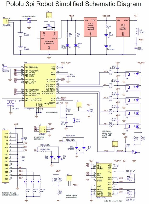
5. How Your 3pi Works Page 22 of 85Pololu 3pi Robot User’s Guide © 2001–2019 Pololu Corporation the loop ends, and the time values are returned. 5.e. 3pi Simplified Schematic Diagram A full understanding of how your 3pi works cannot be achieved without first understanding its schematic diagram: 5. How Your 3pi Works Page 23 of 85
Pololu 3pi Robot User’s Guide   © 2001–2019 Pololu Corporation

5. How Your 3pi Works                            Page 24 of 85
Pololu 3pi Robot User’s Guide                                              © 2001–2019 Pololu Corporation

  You can download a pdf version of the schematic here [https://www.pololu.com/file/0J119/3pi-schematic.pdf]
  (481k pdf).

5. How Your 3pi Works                                                                          Page 25 of 85
Pololu 3pi Robot User’s Guide                                               © 2001–2019 Pololu Corporation

  6. Programming Your 3pi
  To do more with your 3pi than explore the demo program or use it as a serial slave to a master
  device, you will need to program it, which requires a computer and an external AVR ISP programmer
  like our USB AVR programmer v2.1 [https://www.pololu.com/product/3172]. Your programmer’s user’s
  guide should have all the information you need to get started programming AVRs like the one on
  the 3pi. If you are using our USB AVR Programmer v2 or v2.1, you can find it’s user’s guide here
  [https://www.pololu.com/docs/0J67]. You might also check out our original Pololu AVR Programming
  Quick Start Guide   [https://www.pololu.com/docs/0J51]   for tutorials on how to get started programming
  your 3pi in Windows, Linux, and Mac OS X, but it was written for our older USB AVR Programmer, and
  much of it is now out of date.

      Warning: Do not attempt to program your 3pi if its batteries are drained or uncharged (make
      sure you charge any new rechargeable batteries fully before you first use them). Losing
      power during programming could permanently disable your 3pi.

6. Programming Your 3pi                                                                       Page 26 of 85
Pololu 3pi Robot User’s Guide © 2001–2019 Pololu Corporation
7. Example Project #1: Line Following
7.a. About Line Following
Now that you have learned how to compile a
simple program for the 3pi, it’s time to teach your
robot do something more complicated. In this
example project, we’ll show you how to make
your 3pi follow a black line on a white
background, by coordinating its sensors and
motors. Line following is a great introduction to
robot programming, and it makes a great
contest: it’s easy to build a line-following course,
the rules are simple to understand, and it’s not
hard to program your 3pi to follow a line.
Optimizing your program to make your 3pi zoom
Pololu 3pi robot on a 3/4" black line.
down the line at the highest speed possible,
however, is a challenge that can introduce you
to some advanced programming concepts.
A great looking line following course can be constructed for a few dollars in a couple of hours at home.
For information on building your own course, see our tutorial on Building Line Following and Line
Maze Courses [https://www.pololu.com/docs/0J22].
7.b. A Simple Line-Following Algorithm for 3pi
A simple line following program for the 3pi is available in the folder examples\atmegaxx8\3pi-
linefollower .
Note: An Arduino-compatible version of this sample program can be downloaded as part
of the Pololu Arduino Libraries [https://www.pololu.com/docs/0J17] (see Section 5.g).
The source code demonstrates a variety of different features of the 3pi, including the line sensors,
motors, LCD, battery voltage monitor, and buzzer. The program has two phases.
The first phase of the program is the initialization and calibration phase, which is handled by the
function intitialize(). This function is called once, at the beginning of the main() function, before
anything else happens, and it takes care of the following steps:
7. Example Project #1: Line Following Page 27 of 85Pololu 3pi Robot User’s Guide © 2001–2019 Pololu Corporation
1. Calling pololu_3pi_init(2000) to set up the 3pi, with the sensor timeout set to 2000×0.4 us
= 800 us. This means that the sensor values will vary from 0 (completely white) to 2000
(completely black), where a value of 2000 indicates that the sensor’s capacitor took at least
800 us to discharge.
2. Displaying the battery voltage returned by the read_battery_millivolts() function. It is
important to monitor battery voltage so that your robot does not surprisingly run out of
batteries and shut down during the middle of a competition or during programming. For more
information, see Section 2 of the command reference [https://www.pololu.com/docs/0J18].
3. Calibrating the sensors. This is accomplished by turning the 3pi to the right and left on the line
while calling the calibrate_line_sensors() function. The minimum and maximum values read
during this time are stored in RAM. This allows the read_line_sensors_calibrated() function
to return values that are adjusted to range from 0 to 1000 for each sensor, even if some of
your sensors respond differently than the others. The read_line() function used later in the
code also depends on having calibrated values. For more information, see Section 19 of the
command reference [https://www.pololu.com/docs/0J18].
4. Displaying the calibrated line sensor values in a bar graph. This demonstrates the use of
the lcd_load_custom_character() function together with print_character() to make it easy
to see whether the line sensors are working properly before starting the robot. For more
information on this and other LCD commands, see Section 5 of the command reference
[https://www.pololu.com/docs/0J18].
5. Waiting for the user to press a button. It’s very important for your robot not to start driving
until you want it to start, or it could unexpectedly drive off of a table or out of your hands when
you are trying to program it. We use the button_is_pressed() function to wait for you to press
the B button while displaying the battery voltage or sensor readings. For more information
on button commands, see Section 9 of the command reference [https://www.pololu.com/docs/
0J18].
In the second phase of the program, your 3pi will take a sensor reading and set the motor speed
appropriately based on the reading. The general idea is that if the robot is off on either side, it should
turn to get back on, but if it’s on the line, it should try to drive straight ahead. The following steps occur
inside of a while(1) loop, which will continue repeating over and over until the robot is turned off or
reset.
1. The function read_line() is called. This takes a sensor reading and returns an estimate of
the robot’s position with respect to the line, as a number between 0 and 4000. A value of
0 means that the line is to the left of sensor 0, value of 1000 means that the line is directly
under sensor 1, 2000 means that the line is directly under sensor 2, and so on.
2. The value returned by read_line() is divided into three possible cases:
7. Example Project #1: Line Following Page 28 of 85Pololu 3pi Robot User’s Guide © 2001–2019 Pololu Corporation
◦ 0–1000: the robot is far to the right of the line. In this case, to turn sharply left, we set
the right motor speed to 100 and the left motor speed to 0. Note that the maximum
speed of the motors is 255, so we are driving the right motor at only about 40%
power here.
◦ 1000–3000: the robot is approximately centered on the line. In this case, we set
both motors to speed 100, to drive straight ahead.
◦ 3000–4000: the robot is far to the left of the line. In this case, we turn sharply to the
right by setting the right motor speed to 0 and the left motor speed to 100.
3. Depending on which motors are activated, the corresponding LEDs are turned on for a more
interesting display. This can also help with debugging.
To open the program in Atmel Studio, you may go to examples\atmegaxx8\3pi-linefollower and
simply double-click on 3pi-linefollower.cproj . Compile the program, load it onto your 3pi, and try
it out. You should find that your robot is able to follow the curves of your line course without ever
completely losing the line. However, its motors are moving at a speed of at most 100 out of the
maximum possible of 255, and the algorithm causes a lot of unnecessary shaking on the curves. At
this point, you might want to work on trying to adjust and improve this algorithm, before moving on to
the next section. Some ideas for improvement are:
• Increase the maximum possible speed.
• Add more intermediate cases, with intermediate speed settings, to make the motion less
jerky.
• Give your robot a memory: have its maximum speed increase after it has been on the line
consistently for a few cycles.
You might also want to:
• Measure the speed of your loop, using timing functions from Section 17 of the command
reference [https://www.pololu.com/docs/0J18] to time a few thousand cycles or by blinking the
LEDs on and off every 1000 cycles.
• Display sensor readings on the LCD. Since writing to the LCD takes a significant amount of
time, you should do this at most few times per second.
• Incorporate the buzzer into your program. You might want your 3pi to play music while it
is driving or make informational beeps that depend on what it is doing. See Section 3 of
the command reference [https://www.pololu.com/docs/0J18] for more information on using the
buzzer; for music, you’ll want to use the PLAY_CHECK option to avoid disrupting your sensor
readings.
7. Example Project #1: Line Following Page 29 of 85Pololu 3pi Robot User’s Guide © 2001–2019 Pololu Corporation The entire source code to this simple line following program is presented below, for your reference. 7. Example Project #1: Line Following Page 30 of 85
Pololu 3pi Robot User’s Guide                                           © 2001–2019 Pololu Corporation

       1   /*                                                                                     ?
       2    * 3pi-linefollower - demo code for the Pololu 3pi Robot
       3    *
       4    * This code will follow a black line on a white background, using a
       5    * very simple algorithm. It demonstrates auto-calibration and use of
       6    * the 3pi IR sensors, motor control, bar graphs using custom
       7    * characters, and music playback, making it a good starting point for
       8    * developing your own more competitive line follower.
       9    *
      10    * http://www.pololu.com/docs/0J21
      11    * http://www.pololu.com
      12    * http://forum.pololu.com
      13    *
      14    */
      15
      16   // The 3pi include file must be at the beginning of any program that
      17   // uses the Pololu AVR library and 3pi.
      18   #include
      19
      20   // This include file allows data to be stored in program space.   The
      21   // ATmegaxx8 has 16x more program space than RAM, so large
      22   // pieces of static data should be stored in program space.
      23   #include
      24
      25   // Introductory messages. The "PROGMEM" identifier causes the data to
      26   // go into program space.
      27   const char welcome_line1[] PROGMEM = " Pololu";
      28   const char welcome_line2[] PROGMEM = "3\xf7 Robot";
      29   const char demo_name_line1[] PROGMEM = "Line";
      30   const char demo_name_line2[] PROGMEM = "follower";
      31
      32   // A couple of simple tunes, stored in program space.
      33   const char welcome[] PROGMEM = ">g32>>c32";
      34   const char go[] PROGMEM = "L16 cdegreg4";
      35
      36   // Data for generating the characters used in load_custom_characters
      37   // and display_readings. By reading levels[] starting at various
      38   // offsets, we can generate all of the 7 extra characters needed for a
      39   // bargraph. This is also stored in program space.
      40   const char levels[] PROGMEM = {
      41       0b00000,
      42       0b00000,
      43       0b00000,
      44       0b00000,
      45       0b00000,
      46       0b00000,
      47       0b00000,
      48       0b11111,
      49       0b11111,
      50       0b11111,
      51       0b11111,
      52       0b11111,
      53       0b11111,
      54       0b11111
      55   };
      56
      57   // This function loads custom characters into the LCD. Up to 8
      58   // characters can be loaded; we use them for 7 levels of a bar graph.
      59   void load_custom_characters()
      60   {
      61       lcd_load_custom_character(levels+0,0); // no offset, e.g. one bar
      62       lcd_load_custom_character(levels+1,1); // two bars

7. Example Project #1: Line Following                                                    Page 31 of 85
Pololu 3pi Robot User’s Guide © 2001–2019 Pololu Corporation
63 lcd_load_custom_character(levels+2,2); // etc...
64 lcd_load_custom_character(levels+3,3);
65 lcd_load_custom_character(levels+4,4);
66 lcd_load_custom_character(levels+5,5);
67 lcd_load_custom_character(levels+6,6);
68 clear(); // the LCD must be cleared for the characters to take effect
69 }
70
71 // This function displays the sensor readings using a bar graph.
72 void display_readings(const unsigned int *calibrated_values)
73 {
74 unsigned char i;
75
76 for(i=0;iPololu 3pi Robot User’s Guide © 2001–2019 Pololu Corporation
125 print_long(bat);
126 print("mV");
127 lcd_goto_xy(0,1);
128 print("Press B");
129
130 delay_ms(100);
131 }
132
133 // Always wait for the button to be released so that 3pi doesn't
134 // start moving until your hand is away from it.
135 wait_for_button_release(BUTTON_B);
136 delay_ms(1000);
137
138 // Auto-calibration: turn right and left while calibrating the
139 // sensors.
140 for(counter=0;counter= 60)
143 set_motors(40,-40);
144 else
145 set_motors(-40,40);
146
147 // This function records a set of sensor readings and keeps
148 // track of the minimum and maximum values encountered. The
149 // IR_EMITTERS_ON argument means that the IR LEDs will be
150 // turned on during the reading, which is usually what you
151 // want.
152 calibrate_line_sensors(IR_EMITTERS_ON);
153
154 // Since our counter runs to 80, the total delay will be
155 // 80*20 = 1600 ms.
156 delay_ms(20);
157 }
158 set_motors(0,0);
159
160 // Display calibrated values as a bar graph.
161 while(!button_is_pressed(BUTTON_B))
162 {
163 // Read the sensor values and get the position measurement.
164 unsigned int position = read_line(sensors,IR_EMITTERS_ON);
165
166 // Display the position measurement, which will go from 0
167 // (when the leftmost sensor is over the line) to 4000 (when
168 // the rightmost sensor is over the line) on the 3pi, along
169 // with a bar graph of the sensor readings. This allows you
170 // to make sure the robot is ready to go.
171 clear();
172 print_long(position);
173 lcd_goto_xy(0,1);
174 display_readings(sensors);
175
176 delay_ms(100);
177 }
178 wait_for_button_release(BUTTON_B);
179
180 clear();
181
182 print("Go!");
183
184 // Play music and wait for it to finish before we start driving.
185 play_from_program_space(go);
186 while(is_playing());
7. Example Project #1: Line Following Page 33 of 85Pololu 3pi Robot User’s Guide © 2001–2019 Pololu Corporation
187 }
188
189 // This is the main function, where the code starts. All C programs
190 // must have a main() function defined somewhere.
191 int main()
192 {
193 unsigned int sensors[5]; // an array to hold sensor values
194
195 // set up the 3pi
196 initialize();
197
198 // This is the "main loop" - it will run forever.
199 while(1)
200 {
201 // Get the position of the line. Note that we *must* provide
202 // the "sensors" argument to read_line() here, even though we
203 // are not interested in the individual sensor readings.
204 unsigned int position = read_line(sensors,IR_EMITTERS_ON);
205
206 if(position < 1000)
207 {
208 // We are far to the right of the line: turn left.
209
210 // Set the right motor to 100 and the left motor to zero,
211 // to do a sharp turn to the left. Note that the maximum
212 // value of either motor speed is 255, so we are driving
213 // it at just about 40% of the max.
214 set_motors(0,100);
215
216 // Just for fun, indicate the direction we are turning on
217 // the LEDs.
218 left_led(1);
219 right_led(0);
220 }
221 else if(position < 3000)
222 {
223 // We are somewhat close to being centered on the line:
224 // drive straight.
225 set_motors(100,100);
226 left_led(1);
227 right_led(1);
228 }
229 else
230 {
231 // We are far to the left of the line: turn right.
232 set_motors(100,0);
233 left_led(0);
234 right_led(1);
235 }
236 }
237
238 // This part of the code is never reached. A robot should
239 // never reach the end of its program, or unpredictable behavior
240 // will result as random code starts getting executed. If you
241 // really want to stop all actions at some point, set your motors
242 // to 0,0 and run the following command to loop forever:
243 //
244 // while(1);
245 }
7. Example Project #1: Line Following Page 34 of 85Pololu 3pi Robot User’s Guide © 2001–2019 Pololu Corporation
7.c. Advanced Line Following with 3pi: PID Control
A more advanced line following program for the 3pi is available in the folder examples\atmegaxx8\3pi-
linefollower-pid .
Note: An Arduino-compatible version of this sample program can be downloaded as part
of the Pololu Arduino Libraries [https://www.pololu.com/docs/0J17] (see Section 5.g).
The technique used in this example program, known as PID control, addresses some of the problems
that you might have noticed with the previous example, and it should allow you to greatly increase your
robot’s line following speed. Most importantly, PID control uses continuous functions to compute the
motor speeds, so that the jerkiness of the previous example can be replaced by a smooth response.
PID stands for Proportional, Integral, Derivative; these are the three input values used in a simple
formula to compute the speed that your robot should turn left or right.
• The proportional value is approximately proportional to your robot’s position with respect
to the line. That is, if your robot is precisely centered on the line, we expect a proportional
value of exactly 0. If it is to the left of the line, the proportional term will be a positive number,
and to the right of the line, it will be negative. This is computed from the result returned by
read_line() simply by subtracting 2000.
• The integral value records the history of your robot’s motion: it is a sum of all of the values
of the proportional term that were recorded since the robot started running.
• The derivative is the rate of change of the proportional value. We compute it in this example
as the difference of the last two proportional values.
Here is the section of code that computes the PID input values:
1 // Get the position of the line. Note that we *must* provide ?
2 // the "sensors" argument to read_line() here, even though we
3 // are not interested in the individual sensor readings.
4 unsigned int position = read_line(sensors,IR_EMITTERS_ON);
5
6 // The "proportional" term should be 0 when we are on the line.
7 int proportional = ((int)position) - 2000;
8
9 // Compute the derivative (change) and integral (sum) of the
10 // position.
11 int derivative = proportional - last_proportional;
12 integral += proportional;
13
14 // Remember the last position.
15 last_proportional = proportional;
Note that we cast the variable position to an int type in the formula for proportional. An unsigned
int can only store positive values, so the expression position-2000 , without casting, would lead to a
7. Example Project #1: Line Following Page 35 of 85You can also read