Smart City Network Architecture Guide - Alcatel-Lucent ...
←
→
Page content transcription
If your browser does not render page correctly, please read the page content below

Smart City Network
               Architecture Guide

Guide
Smart City Network Architecture Guide
Table of Contents

1 About this document..........................................................................................................3
     1.1 Purpose .......................................................................................................................................................3
     1.2 Audience .....................................................................................................................................................3
     1.3 Scope.............................................................................................................................................................3

2 Introduction and use cases..............................................................................................3
3 Solution Overview...............................................................................................................5
4 Reference Architecture......................................................................................................7
5 City Net....................................................................................................................................8
     5.1 Introduction................................................................................................................................................8
     5.2 Business Drivers and Technical Requirements.............................................................................8
     5.3 L2/L3 VPNs and IoT Containers.........................................................................................................9
     5.4 The Intelligent Fabric in City Nets..................................................................................................11
     5.5 Solution Highlights...............................................................................................................................11
     5.6 Why ALE’s Intelligent Fabric for Smart City Nets?..................................................................12

6 Municipal Cloud................................................................................................................. 12
     6.1 Introduction.............................................................................................................................................12
     6.2 Business Drivers and Technical Requirements..........................................................................12
     6.3 The Virtualized Data Centre..............................................................................................................13
     6.4 End-2-End Virtualized Hybrid Multi-Tenant Cloud..................................................................13
     6.5 Solution Highlights...............................................................................................................................14
     6.6 Why ALE’s Intelligent Fabric for Smart Municipal Clouds?...................................................14

7 Architecture........................................................................................................................ 15
     7.1 Introduction & Overview....................................................................................................................15
     7.2 Core and Border Topology.................................................................................................................16
     7.3 Backbone and Edge Topology..........................................................................................................17
     7.4 VPN Services...........................................................................................................................................18

8 Management Service Architecture............................................................................. 26
9 Internet Service Architecture....................................................................................... 29
10 Security Framework...................................................................................................... 32
     10.1 Securing IOT Devices.........................................................................................................................33
     10.2 Securing the Perimeter....................................................................................................................33
     10.3 Securing the Network.......................................................................................................................33

11 Conclusion......................................................................................................................... 37
12 Acronyms ......................................................................................................................... 37
13 Related documents........................................................................................................ 38

Guide
Smart City Network Architecture Guide                                                                                                                                     2
1 About this document
1.1 Purpose
The purpose of this architecture guide is to present the requirements and considerations relevant
to Smart City networks along with design options, best practices and configuration guidelines.

1.2 Audience
This design guide is intended for network architects and network engineers involved in the
design, implementation and maintenance of Smart City networks.

To take advantage of this document, it is expected that the reader will be familiar with Shortest
Path Bridging and will have a solid understanding of various networking technologies at the
ACPS or similar level.

Please refer to [1] for a short introduction to SPB.

1.3 Scope
This document will focus on Smart City Nets and Municipal Clouds. Municipal Wi-Fi, Smart
Transit, Smart Roads & Highways and Smart Civic Venue solutions are out of scope.

2 Introduction and use cases
According to the Smart City Council, “A smart city uses information and communications
technology (ICT) to enhance its liveability, workability and sustainability. First, a smart city
collects information about itself through sensors, other devices and existing systems. Next,
it communicates that data using wired or wireless networks. Third, it analyses that data to
understand what’s happening now and what’s likely to happen next.”1

Figure 1. Smart City

           Smart                 Smart             Smart             Smart             Smart       Smart       Smart
       transportation            retail          hospitality       education          banking   government   healthcare

1 https://rg.smartcitiescouncil.com/readiness-guide/article/definition-definition-smart-city

Guide
Smart City Network Architecture Guide                                                                                     3
Through this data collection, sharing and analysis, a Smart City can improve on multiple aspects.
Let’s review some of the most common use cases with practical examples shown in Table 1 below.

Table 1. Use Cases and Examples

 Use case                  Example
 Smart Lighting            Save energy with remotely-controlled on-off timing and dimming depending on time of year,
                           weather conditions and motion detection, such as an approaching cyclist.
                           Example: Public lighting represents 20% of energy consumed by Barcelona City Council.2
                           Replacing old-fashioned sodium lamps with LED ones provides better lighting and reduces energy
                           usage by more than 52%.
                           With the addition of remotely-controlled on-off timing and dimming depending on time of the
                           day, or year, weather or other conditions as well as motion detection, such as approaching cyclists,
                           energy savings of up to 72% are feasible.
 Smart Parking             Reduce parking search time, fuel usage, CO2 emissions, and parking violations by detecting
                           available parking spots and guiding drivers to them with an app.
                           Example: City drivers spend a significant amount of time looking for a parking spot. Sensors can
                           detect parking spot availability and a Smart Parking app can guide drivers to it. In the city of San
                           Francisco, parking search time was reduced by 43% which not only saves time but also reduces fuel
                           usage and CO2 emissions by 30%3. In addition, in-app payment makes it easier to pay, resulting in
                           a 23% decrease in the number of parking violations and citations.
 Smart Transit             Improve rider safety and satisfaction as well as ridership with video surveillance, on-board Wi-Fi
                           and entertainment and real-time schedule information. Real-time vehicle location tracking provides
                           live updates through an app or smart display at the bus stop.
                           Example: In Bucharest, visually-impaired riders are alerted that their bus is approaching4. And bus
                           drivers can be informed that someone may need assistance with boarding at the next stop.
                           With Open Data, real-time location information can be leveraged by 3rd party solutions for
                           wayfinding and more.
 Smart Waste               Reduce waste collection activities, fleets, fuel usage and CO2 emissions with smart bins that can
 Management                compact waste and inform their fill level.
                           Example: Solar-powered smart rubbish bins can compact waste, increasing their capacity by a factor
                           of 5. Bins use sensors to determine their fill status and communicate it to the management platform.
                           In Australia5, smart bin deployment has resulted in a 75% reduction in waste collection activities at
                           Bondi Beach. With real-time access to bin fill-level information, waste collection is optimized with
                           smarter routes, resulting in reduced labour costs, fleets, fuel usage and CO2 emissions.
 Smart Metering            Reduce water and electricity waste or theft with smart meters that can measure and report usage
                           in near real-time.
                           Example: Smart Meters measure energy and water usage in short intervals and report this data back
                           to the energy or water company. Utilities can set dynamic usage-based pricing to reduce usage at
                           times of peak demand. Smart metering also helps reduce waste and eliminate the need to dispatch
                           technicians for costly manual meter readings as well as facilitate trading of excess energy. Smart
                           Meters can detect and alert of energy theft in public infrastructure such as public lighting.
 Video Surveillance        Improve public safety with license plate recognition, vehicle tracking, facial recognition and
                           analytics.
                           Example: Cities cannot be smart if they are not safe. Smart video surveillance solutions add
                           features such as license plate recognition, vehicle tracking, and analytics. Facial recognition can
                           identify a suspect, or persons of interest, such as people on a watch list, from a crowd. But it’s not
                           just about safety. Facial recognition can be up to 50% faster6 compared to tap cards when used at
                           metro gates.

2 http://ajuntament.barcelona.cat/ecologiaurbana/en/services/the-city-works/maintenance-of-public-areas/energy-management/street-lighting-management
3 https://www.sfmta.com/press-releases/sfpark-evaluation-shows-parking-easier-cheaper-pilot-areas
4 http://www.rfidjournal.com/articles/view?13899
5 https://www.iothub.com.au/news/council-introduces-smart-bins-to-bondi-464281
6 http://www.straitstimes.com/singapore/transport/face-reading-system-can-replace-fare-cards

Guide
Smart City Network Architecture Guide                                                                                                             4
3 Solution Overview
If we pay close attention to the use cases presented in Section 2, we may notice that they
require a network to function. Some use cases are unfeasible without network connectivity
(e.g. smart metering). Other use cases cannot deliver their full benefits in an offline manner
(e.g. smart lighting).

Figure 2 illustrates a high-level view of a Smart City infrastructure.

Starting at the bottom of this diagram, we have IoT Devices and Users. IoT devices are a variety
of sensors and actuators, the sensory nerves and the muscles. IoT devices gather data and are
commanded by the City’s brain, software and applications running in a Municipal Cloud and the
City’s Command and Control Centre.

A Smart City leverages its ICT infrastructure to maintain smart interactions with residents and
visitors, the users. Users consume and produce data as they go about their daily lives utilizing
the City’s resources such as public transport, parking, Wi-Fi and so on. Users interact with
City’s agencies directly through official websites and applications, or, indirectly, with 3rd party
websites and applications that access agency Open Data through APIs. Users connect through
fixed (e.g. POL or ADSL) or mobile (e.g. 4G or LTE) broadband connections or Wi-Fi using a
personal device, such as mobile phone, or a City asset, such as an information kiosk.

IoT devices can connect using the same technologies available to users. In other cases, however,
other technologies are more appropriate. An IoT gateway may be required to connect such
devices to IP-based infrastructure.

Let’s have a look at some of those technologies.

SCADA: SCADA is a control technology which is prevalent in many industrial and infrastructure
processes. As an example, SCADA may be found in power utilities, water, or wastewater
collection and treatment. Modern SCADA devices can connect to an IP network directly. Legacy
SCADA devices, however, utilize a serial interface and require a gateway to connect to the IP
network.

WPAN: WPAN stands for “Wireless Personal Area Network”. These technologies are designed
to connect medium-bitrate devices operating on a battery over a short distance (i.e. 10 to 20
meters). This distance can be extended by “meshing” to other WPAN devices. Bluetooth and
Zigbee are examples of WPAN technologies. WPAN technologies are useful in short-range
applications such as those within a “Smart Building”.

LPWAN: LPWAN stands for “Low-Power Wide Area Network”. These technologies are designed
to connect low-bitrate devices operating on a battery, such as sensors, over long distances.
Examples of LPWAN technologies include Lora/LoRaWAN, Sigfox and NB-IOT. These technologies
are useful in low-density, long-range deployments.

The City’s network is the spinal cord linking IoT devices with the software, applications and
people that analyse their data and control them. The City’s network delivers network services
to government agencies, businesses and users over different technologies. Section 5 introduces
ALE’s solution for Smart City Nets.

The Command Centre is the facility where government personnel manage incident and analyse
data for better city planning. The Command Centre also acts as the City’s emergency and disaster
management centre supporting multiple agencies (e.g. law enforcement, public transport,
environmental, etc.).

Guide
Smart City Network Architecture Guide                                                                 5

Figure 2. Smart City Infrastructure

                                               Smart home

                      Business broadband
                                                  Broadband
            Video surveillance

  Smart lighting                                                                  100G

          Bike sharing
                                                                    Metro E
                                                                                                                 ...
Command center
                                                              NTU

                                                                    IoT gateway

                                               Public
                                               Wi-Fi

                                                                                           Smart Apps – Storage – DCHP/DNS – AAA

ALE’s network solutions enable Smart City use cases. In this document, we will focus on 6 Smart
City solution sets shown in Figure 3 below. This architecture guide focuses on the City Net and
Municipal Cloud solution sets. These solution sets are described in Sections 5 and 6.

Figure 3. Smart City Solution Sets

                   City Net                                                   Municipal Wi-Fi
                   City-wide
                       -      fabric to interconnect                          Municipal Wi-Fi provides amenity to
                   government agencies, residents,                            visitors and residents and enables
                   visitors, businesses and IoT devices.                      multiple smart city use cases.

                   Municipal cloud                                            Smart Civic venue
                   End-to-end virtualized and consolidated                    Location and wayfinding enables
                   cloud enables smart city use cases by                      various use cases such as visitor
                   breaking siloes whilst at the same time                    guides, geo-fenced alerts and more.
                   achieving economies of scale.

                   Smart transit                                              Smart roads and highways
                   Dedicated solutions for on-board                           Reducing congestion, improving safety
                   communications and smart shelters.                         and keeping drivers informed in real time.

Guide
Smart City Network Architecture Guide                                                                                              6
4 Reference Architecture
Implementing these use cases requires breaking organizational siloes: information must
be shared and budgets must be pooled across multiple government agencies for this to be
technically feasible and cost-effective. A siloed architecture in which each vertical use case
relies on its own infrastructure, middleware and applications increases complexity and cost.

The ALE reference architecture for Smart Cities is shown in Figure 4 below. This horizontal
architecture makes common infrastructure and services layers available to use cases and
applications.

This approach has the following advantages:
• Facilitates sharing of information across different use cases and applications, a key
  requirement of Smart Cities.
• Consolidates network, cloud and services in shared layers which are abstracted from and
  consumed by applications, thus simplifying application development.
• Eliminates multiplication of infrastructure and middleware performing similar functions,
  thus reducing TCO.

The Alcatel-Lucent Enterprise Intelligent Fabric architecture enables this horizontal approach
through:
• Automated network node provisioning (ZTP/RCD)
• Automated IoT device provisioning (Access Guardian/UNP)
• Service-oriented architecture (SPB/VXLAN/GRE)
• Northbound APIs (OmniSwitch/OmniVista)

Figure 4. ALE Smart City Reference Architecture

        Parking                Transit                Video Surveillance            Waste Management                 Lighting                    +

                                                                 Smart City use cases

                                                                     Services layer

    Analytics       Control                Location       Communications           Management          Security             Data Repository    Data Broker

                                                                     Data Center Fabric

                                                                   Smart City Cloud

                              L2/L3 VPNs                                                                          IoT Containers

                                                                     Smart City Net

                                                                                                                                IoT gateways
                  Municipal
  Ethernet                               Broadband          Bluetooth                Cellular
                   Wi-Fi
                                                                                                        WPAN                       LPWAN             SCADA

Guide
Smart City Network Architecture Guide                                                                                                                        7
5 City Net
5.1 Introduction
Smart Cities rely on a robust, yet flexible network foundation to interconnect sensors, people
and businesses with cloud-based applications. The City Net is the cornerstone of the Smart City
since all use cases are reliant on it.

Figure 5. Cornerstone of a Smart City

                                  Citizens                                                     Tourists
                                                                        Police
                                                                        safety
                                                             Taxes,                 Urban
                                                            finances               planning

                                               Welfare,                                       Culture
                                               Seniors                                        Tourism               Partners
                                               Disabled                                        Parks

                                             Economy                                          Transportation
                                               Jobs

                                                Waste
                  Representatives             maangement                                   Streets, roads

                                                                                                                           Other
                                                                                                                        government
                                                            Sports                 Waste
                                                          equipment                water
                                                                        Youth
                                                                       Childcare

                                    Government                                                              IoT
                                    employees

5.2 Business Drivers and Technical Requirements
Let’s review the 3 main business drivers of a City Net in Figure 6 below.

Figure 6. City Net Business Drivers

                                                                Improve
                                                             competitiveness
                                                       Attract businesses and start-ups
                                                          with fast connectivity and
                                                       skilled workforce. Generate new
                                                       sources of quality employment.

          Smart City cornerstone                                                                                   Cost effectiveness
                                                                                                                  Take advantage of economies
           Support Smart City initiatives.                                                                           of scale to lower costs
             Improve service efficiency,                                                                            through ownership, bulk-
           enhance safety & security and                                                                             buying or wholesale of
            promote better life quality.                                                                               network services.

Guide
Smart City Network Architecture Guide                                                                                                           8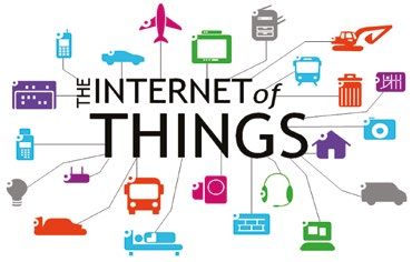
We can now translate these business drivers into technical requirements in Table 2 below.

Table 2. City Net Technical Requirements

 Technical requirements
 Multi-Tenancy        The City Net provides services to multiple tenants. L3 VPN services are needed for most
                      Government agencies, schools and hospitals. L2 VPN services are needed in specific situations
                      such as DC interconnect. IoT devices of different class need to be isolated in their own L2 or L3
                      container for security.
 Availability         Availability is of utmost importance since the City Net provides services to multiple agencies and
                      supports multiple use cases. The City Net must implement redundancy at all layers to protect from
                      node or link failure and to facilitate in-service maintenance. In the event of a failure, the network
                      must reconverge in under 1s.
 Scalability          The City Net architecture must be scalable to support the required number of tenants, containers,
                      devices and users as well as bandwidth and multicast flows, etc.
 Simple Operations    The City Net can be comprised of thousands of network nodes and IoT devices. Because of its size,
                      template-driven automatic provisioning of nodes and devices is necessary to reduce deployment
                      cost, time and errors.
 Security             Because a Smart City Net supports mission-critical infrastructure, security is even more critical
                      than traditional Enterprise security. A multi-layered approach is required including security
                      hardening of nodes and devices, network admission control (NAC) and role-based access, protection
                      of data integrity and confidentiality as well as quarantine and remediation among others.
 Environmental        Smart City Net nodes will be deployed in locations such as within a roadside cabinet where they
                      will be subject to extreme temperatures, dust, vibration and shock. The network devices must
                      tolerate such harsh conditions.

5.3 L2/L3 VPNs and IoT Containers
Figure 7 below illustrates the concept of L3 VPNs for government agencies, schools and
hospitals. In this diagram, schools, hospitals and other government agencies are tenants of the
City Net and each have their own L3 VPN. VPN technology ensures all these different tenants
can coexist on the same infrastructure and that tenant data is kept private form other tenants.
In a L3 VPN, tenants exchange routes with the City Net and the City Net routes tenant data from
site to site over the most optimal route without traffic tromboning back and forth to a central
site for routing. In addition, tenant data is isolated from other tenants and tenant routes are not
advertised to other tenants.

Figure 7. City Net L3 VPN

                                                                                               ✓      More
                                                                                                      scalable

                                                          Health Net

                                             School Net                Gov’t Net

Guide
Smart City Network Architecture Guide                                                                                         9
Figure 8 below illustrates the concept of L2 VPNs for DC interconnect. In this diagram, 2 DC
locations are interconnected by L2 Services. These DCs provide services to different tenants. Unlike
L3 VPN services, in a L2 service there is no exchanging of routes between tenant and City Net, any
routing is done by the tenant and data is simply bridged across the City Net. This L2 communication
is a requirement in certain scenarios, such as DC interconnect, because it enabled VM mobility an
HA across both locations. A L2 VPN also isolates tenant data from other tenant’s data.

Figure 8. City Net L2 VPN

                                                                                                                             Subnet A
                                                                                                                             Subnet B
                                                                                                                             Subnet C

        DC1                                                                                                                             DC2

         ✓        Active/
                  Active               ✓          VM
                                                  mobility           ✓        Optimal
                                                                              paths
                                                                                                               MAC
                                                                                                               learning
                                                                                                                                     Spanning
                                                                                                                                     Tree

Finally, Figure 9 below illustrates the concept of IoT Containment. In this figure, multiple
different types of IoT devices such as sensors, actuators, cameras and door locks are connected.
IoT devices are grouped into different containers: Utility, Administration, Security, etc. This
containerization increases security because a container is isolated from other containers and
devices in different containers can only communicate through a Firewall. In addition, devices
are mapped to containers according to the device type using authentication (MAC or certificate-
based 802.1x). Once the device type and container is determined, the device is bound to a
profile which will also restrict communication with other devices, even if on the same container,
and apply fine-grained QoS policies to the device.

Figure 9. IoT Containers

                                                        Water plant                                 Administration office

               Electricity plant

                                     Restaurant                                         Tourism                             School
                                                                                         office   Admin

                             Agent                           Agent
                                                                      Leisure Cr Dir.             Front desk

                                                                                                               Actuators
                                                                       Utilities network
                                                  Sensors
   Universal profile
   Authorize

   Classify

   Auto                 Container
   Provision            Quality
                        Security

Guide
Smart City Network Architecture Guide                                                                                                           10
5.4 The Intelligent Fabric in City Nets
The Intelligent Fabric is based on the IEEE standard protocol Shortest Path Bridging. Let’s
compare this technology with others such as legacy (VLANs and Spanning Tree Protocol) and
MPLS (Multi-Protocol Label Switching). As we can see, SPB is superior for small to medium-
sized City Nets because it is much simpler to deploy and operate, resulting in lower total
cost of ownership.
Table 3 - SPB Comparison
Legacy (VLAN/STP) MPLS SPB
Virtualization VLAN VPN VPN
Availability Slow fault recovery Fast fault recovery Fast fault recovery
Performance Single active path Multiple active paths Multiple active paths
Scalability Small networks Very large networks Large networks
Complexity/Operational Costs Low/High High/High Medium/Low
Limited High Cost Best Option
5.5 Solution Highlights
Table 4 below shows the most relevant ALE products for a Smart City Net solution and the
typical role that they may fulfill along with the key network and environmental features and
market-specific certifications that make them a good fit for the role.
Table 4. City Net Solution Highlights
Product Role Key environmental features Key network features Market-specific certifications
OmniSwitch 6865 Advanced hardened • Fan-less • ERPv2, SPB • NEMA-TS2 (Traffic
Access or collapsed • Shock, vibration, • OAM Controller Assemblies)*
Access + backbone temperature • POE/POE+*/UPOE* • CC EAL-2 & NDcPP
• IP-30 rating* • Virtual Chassis/ISSU* • FIPS-140
• IEEE 1588v2
OmniSwitch 6465 Value hardened access • Fan-less • ERPv2 • NEMA-TS2 (Traffic
• Shock, vibration, • OAM* Controller Assemblies)*
temperature • POE/POE+*/UPOE* • CC EAL-2 & NDcPP
• IP-30 rating* • Stacking • FIPS-140
• Alarm replay inputs
• MACSec*
• IEEE 1588v2
OmniSwitch Value access/smart • Extended temperature • ERPv2 • CC EAL-2 & NDcPP
6350/6450/6465T/6560 building range (6465T only)* • OAM* • FIPS-140
• POE/POE+*/UPOE*
• Stacking
OmniSwitch Aggregation, backbone, - • ERPv2, SPB • CC EAL-2 & NDcPP
6860/6900/9900 core • OAM • FIPS-140
• Virtual chassis/ISSU
• MACSec*
• IEEE 1588v2
OmniVista 2500 Network Management - • Network Management -
NMS System • Unified access
• Analytics
Guide
Smart City Network Architecture Guide 115.6 Why ALE’s Intelligent Fabric for Smart City Nets?
Let’s review the key reasons that make ALE’s Intelligent Fabric a great fit for the Smart City’s
network in Figure 10 below.
Figure 10. Why ALE’s Intelligent Fabric in Smart City Nets
Simplicity Convergence Security
SPB delivers MPLS-like features in One physical network with multiple VPNs and containers segregate
a much simpler way, resulting in faster virtual containers. Converged electrical organizations and IoT devices. Network is
deployments and simpler operations. and data wiring. Integrates with MPLS and protected from attacks. Data is encrypted
Further simplification with single OS and GPON. Standard and Harsh environments. and protected against unauthorized access
management system and plug&play for or tampering.
network nodes and IoT devices.
Simplification reduces costs. Convergence reduces costs. Mission-critical security
6 Municipal Cloud
6.1 Introduction
The Municipal Cloud serves two main purposes:
• Hosting the multiple systems, applications, databases, etc, powering the various Smart City
use cases (e.g. Smart Lighting, Smart Waste Management, etc). The Smart City’s “brain”.
• Hosting systems, applications, databases, etc, for Smart City Net customers, such as
government or private organizations, hospitals and schools.
The Municipal Cloud may also provide additional services such as Email. Web, caching, storage,
content delivery network (CDN), voice communications and IP TV.
6.2 Business Drivers and Technical Requirements
Let’s now review the 3 main business drivers of a Municipal Cloud in Figure 11 below.
Figure 11. Municipal Cloud Business Drivers
Breaking silos
Sharing information between
government agencies and with
the public through applications,
services and open data
initiatives.
Smarts Cost effectiveness
Consolidate budgets and take
Integrate management,
advantage of economies of
analytics, control and
scale to lower costs through
applications that power
ownership, bulk-buying
smart city solutions.
and wholesale.
Guide
Smart City Network Architecture Guide 12We can now translate these business drivers into technical requirements in Table 5 below.
Table 5. Municipal Cloud Technical Requirements
Municipal cloud Technical requirement
Multi-Tenancy The Municipal Cloud will provide services to multiple tenants including government and
private organizations. Tenants must be isolated from one another for security reasons and
to avoid conflicting IP addressing issues. Tenant traffic must be seamlessly stitched from
the City Net to Municipal Cloud, across DC sites and between the private and public cloud.
Business Continuity The Municipal Cloud must recover from multiple failure scenarios without disruption to
customers. To accomplish this, Active/Active intra- and inter-DC redundancy with no single
point of failure and sub-second convergence is required.
Elasticity Customers must be able to scale their workloads up and down both on-site at the
Municipal Cloud DC sites or off-site across the public cloud.
Fluid Operations Manual intervention to Moves, Adds and Changes should be minimized. The network must
automatically adapt to event such as Virtual Machine Mobility. Operators should be able to
perform software upgrades in-service without disruption to customer traffic.
Performance The Municipal Cloud must offer high throughput and low latency, lossless capability for
storage convergence as well as monitoring and optimization of workload performance.
Sustainability The Municipal Cloud must operate within a compact footprint and with low power
consumption and cooling requirements.
6.3 The Virtualized Data Centre
The municipal cloud also adopts a layered horizontal architecture to break siloes and reduce
costs by consolidating and sharing common functions across the board.
The Municipal Cloud can extend across multiple physical Active/Active Data Centres for high
availability and load sharing. The Municipal Cloud can also extend to Public Clouds for elasticity
or to exchange information with those clouds. Containers abstract these aspects such that, to the
application and the customer, the container appears to be a virtual DC. Please refer to Figure 12 below.
Figure 12. Virtualized Municipal Cloud
Public cloud
Schools Government
virtual DC virtual DC
Health virtual
DC
Smart City Services
virtual DC Municipal cloud virtual DC
DC1 DC2
City Net
6.4 End-2-End Virtualized Hybrid Multi-Tenant Cloud
City Net containers extend deep into the data centres and all the way through the Top-of-Rack
(TOR) switch down to the Virtual Machine (VM). This deep containerization keeps different
organizations applications and data isolated end-2-end. This not only improves security, but also
facilitates migration of hardware and applications from on-premises DC to the Municipal Cloud.
Regardless of where the application is hosted (primary or secondary DC or even the public cloud)
it is mapped to the appropriate container. Secure containerization is maintained seamlessly
across DC sites and the public cloud and from the IoT device at the edge of the network all the
way to the application that controls it. Refer to Figure 13 on the following page.
Guide
Smart City Network Architecture Guide 13Figure 13. End-2-End Virtualized Hybrid Multi-Tenant Cloud
Health cloud
E2E Virtual Cloud from Site to Rack/VM
Gov’t cloud
Safety cloud
City Net
Rack Rack Rack Rack
DC1 DC2
Multi-Site Hybrid Municipal Cloud
6.5 Solution Highlights
Table 6 below shows the most relevant ALE products for a Smart Municipal Cloud solution and
the typical role that they may fulfill along with the key network and environmental features and
market-specific certifications that make them a good fit for the role.
Table 6. Municipal Cloud Solution Highlights
Product Role Key network features Specific features Ports
OmniSwitch 9900 Modular Spine Node • Virtual chassis In-line routing 1G/10G/25G/40G/50G/100G
OmniSwitch 690-C32 Stackable 100G • SPB VXLAN Gateway 1G/10G/25G/40G/50G/100G
Spine Node • VM Snooping
• VM Mobility
OmniSwitch 6900-Q32 Stackable 40G Spine 1G/10G/40G
• VM Profiles
Node
• Lossless Ethernet
OmniSwitch 6900-V72 Stackable 25G Leaf • FIP Snooping 1G/10G/25G/40G/50G/100G
Node • RESTful API
OmniSwitch 6900-X72 Stacakable 10G Leaf • OpenFlow 1G/10G/40G
Node • Python
programmability
OmniSwitch 6900- Semi-modular 10G FC Gateway 1G/10G/40G/FC
X20/40 Leaf Node • ZTP
• App fingerprinting
OmniSwitch 690- Semi-modular 10G 1G/10G/40G/10G-T/FC
T20/40 Copper Leaf Node
OmniVista 2500 NMS • VM Mobility/
Snooping
• SPB, VXLAN
• RESTful API
• Analytics
6.6 Why ALE’s Intelligent Fabric for Smart Municipal Clouds?
Let’s review the key reasons that make ALE’s Intelligent Fabric a great fit for the Smart City’s
Municipal Cloud in Figure 14 on the following page.
Guide
Smart City Network Architecture Guide 14Figure 14. Why ALE’s Intelligent Fabric for Smart Municipal Clouds
Service-oriented Simpler Seamless
ALE’s Intelligent Fabric technology brings ALE’s Intelligent Fabric meets the Seamless multi-site HA across the WAN
service and container segregation all the requirements of both DC fabrics and City and elasticity towards the public cloud.
way into the DC rack whilst also providing Nets with a single technology. Operations Network automatically reconfigures on
multi active, low-latency paths. are simplified with a single OS and NMS VM moves, adds and changes. In-service
across the board. upgrades.
Economies of scale. Simplification reduces costs. Mission-critical HA.
7 Architecture
7.1 Introduction & Overview
A City Net may serve different purposes such as:
• VPN/Internet services for private and government organizations, hospitals, schools, etc.
• Smart City use cases such as Smart Lighting, Video Surveillance, Public Wi-Fi, etc.
• Residential or Business Internet Access
• Mobile backhaul.
This section will describe the architecture focusing primarily on the first two. The City Net offers
the following services:
• L2 VPN: E-LINE (point to point) or E-LAN (multipoint) service.
• L3 VPN: Multipoint IP VPN.
• Internet: Transit to other local or regional/national ISPs.
• Wholesale: Local termination of other carrier or ISP services.
Let’s refer to Figure 15. This diagram is showing the architecture for a small city network. A
small city can be served with a single POP (Point of Presence). The POP is wholly contained
within a single metropolitan area.
Figure 15. City Net Architecture Overview
Upstream carrier Upstream ISP Local IXP
Border
Core
DC1/NOC DC2/DR
Backbone
Enterprise Mobile
services backhaul
edge edge
Business Residential
services services
edge edge (FTTx)
Guide
Smart City Network Architecture Guide 15• Core: This is the City Net’s Core and the rest of the City Net connects to it through the
Backbone. The Core may be physically split between two sites for redundancy. These two sites
are usually co-located with redundant DC1 and DC2 as well as the NOC and DR sites as shown
in the diagram.
• Border: The Border block is the point of demarcation between the City Net and 3rd party
upstream and local ISPs. Border nodes are also usually co-located with DC1 and DC2.
• DC1 and DC2: These two Data Centres operate in an Active/Active redundancy scheme. DC1
and DC2 provide essential network services such as DHCP/DNS and value-added services such
as Email, WWW, firewalling, web-caching or CDN (Content Delivery Network), IP Telephony
and IPTV. DC1 and DC2 also offer hosting, co-location and “cloud” services to the City Net’s
customers such as public or private organizations and businesses. DC1 and DC2 also host the
applications and services implementing Smart City use cases such as Smart Lighting and
Video Surveillance.
• NOC and DR: The Network Operations Centre is the facility where the City Net is monitored
and managed from. A DR (Disaster Recovery) site may also replicate the NOC at a separate
location such that NOC activity can quickly resume in the event of a major disruption.
• Backbone: The Backbone block is an aggregation layer linking Edge blocks with the Core.
In smaller cities or communities, the Backbone and Edge blocks may be collapsed in a
single block.
• Edge: Edge blocks are aggregation layers linking customer connections with the backbone.
Different Edge blocks such as Enterprise, Business, Residential or Mobile Backhaul provide
different services. For instance, the Enterprise edge provides Enterprise-grade L2/L3 VPN and
Internet services whilst the Residential block provides Internet services over a FTTH (Fibre to
the Home) connection.
• Upstream ISP: The City Net needs to connect to at least one ISP, such as a regional ISP, to
communicate with the rest of the Internet.
• Local IXP: The City Net may connect with other local ISPs at an IXP (Internet Exchange Point).
The benefit in this is that, unlike traffic transiting through the upstream ISP, peering with
other local ISP is free of charge.
• Upstream Carrier: City Net customers may require services in locations not within the City
Net’s footprint (off-net). Conversely, other carrier customers may require network services
within the City Net’s footprint (on-net). Interconnection with other carriers at enables cross-
selling of network services to cater to these situations.
7.2 Core and Border Topology
Let’s refer to Figure 16 below.
Figure 16. Core and Border Topology
Upstream carrier Upstream ISP Local IXP
Border BEB1 Border BEB2
Core BCB1 Core BCB2
NOC NOC
Services Services
DC1 BEB DC2 BEB
Hosting Backbone Hosting
co-location co-location
Guide
Smart City Network Architecture Guide 16The Core and Border blocks serve the following functions:
• Backbone aggregation
• Interfacing with other ISPs or carriers
• NOC connection
• Services connection
• Hosting and co-location connection
The Core and Border blocks are comprised of three different node types according to the
functions that they perform. In a smaller network however, more of these functions may be
performed by the same node.
• Core BCBs: These nodes are pure Core nodes which means they do not directly connect to any
external party (e.g. ISP or customer) and do not terminate any service, except for Internet and
Management services which, as we will see later one, are implemented as separate services.
For this reason, these nodes require little touch.
• Border BEBs: These nodes are a point of demarcation between the City Net and other ISPs or
carriers. Routing and security policies are enforced on these nodes.
• DC BEBs: These nodes connect the NOC, essential services blocks and other customer services
hosted or co-located at the DC sites.
Note that nodes in Figure 16 are illustrated as modular chassis but they can be standalone stackable devices or a
Virtual Chassis. Also note that hairpins or s-hooks required for routing or service mapping are not shown.
7.3 Backbone and Edge Topology
Let’s refer to the topology shown on Figure 17 below.
Figure 17. Backbone and Edge Topology
BCB
BEB Core
CE
Backbone
Edge Edge
Edge Edge
In this diagram, we are using ring topologies as an example. Ring topologies support redundant
physically-diverse paths and minimize fibre runs when compared to other topologies such as
star or mesh. For these reasons, ring topologies are very common when a large area needs to
be covered. It should be noted however that the same design principles are applicable to any
topology because SPB is powered by a link-state protocol (IS-IS) and therefore supports any
topology. We are also showing one backbone block and several edge blocks. Larger networks
may have several backbone blocks and smaller networks may collapse backbone and edge
blocks in a single block.
Backbone nodes are SPB BCB nodes because they do not terminate any customer service.
The only exception is, as we will see later, Internet and Management services.
Guide
Smart City Network Architecture Guide 17Edge blocks are comprised of Edge BEBs. These nodes terminate customer services such as
L2/L3 VPN. Edge blocks redundantly connect to diverse Backbone BCBs.
Customer Edge (CE) devices connect to one or more BEBs. Please refer to Section 7.4.1 for the
various CE connection redundancy options.
Note that nodes in Figure 17 may be standalone stackable, VC or modular chassis. Also note that
hairpins or s-hooks required for routing or service mapping are not shown.
7.4 VPN Services
Figure 18 below illustrates a L2 service interconnecting three customer sites. This is an example
of multipoint (E-LAN) L2 service. From the customer’s point of view, this would be equivalent to
having all three sites connected to an Ethernet switch. Within the City Net, customer traffic is
isolated in its own ISID.
Figure 18. L2 Service
BCB
BEB Core
CE
Edge Backbone
Cust A ISID Edge
Customer A Customer A
Site 1 Edge Edge Site 3
Customer A
Site 2
Figure 19 below illustrates a L3 service interconnecting three customer sites. This is an example
of multipoint IP-VPN. From the customer’s point of view, this would be equivalent to having all
three sites connected to an Ethernet router. Customer sites can exchange routing information
using standard protocols such as OSPF or simply use static or default routes. Within the City Net,
customer traffic is isolated in its own ISID and VRF.
Figure 19. L3 Service
BCB
BEB Core
CE
L3 Edge Backbone
Cust A Edge
ISID/VRF
Edge Ege
Guide
Smart City Network Architecture Guide 18Let’s define the elements in these diagrams. • CE: Customer Edge. This device is located on customer premises but is owned and managed by the City Net. The CE device connects to and peers with the BEB. In a L2 Service, the CE device is a L2 device. In a L3 service, the CE device may be a L3 device particularly when each site has multiple subnets. For smaller sites, the CE device can be a L2 device and routing can be done by the BEBs. • BEB: Backbone Edge Bridge. An SPB switch located at the edge of the City Net. The BEB connects CE devices to the City Net. A BEB may also connect to third party PE (Provider Edge) nodes. • BCB: Backbone Core Bridge. An SPB switch located within the City Net network. A BCB connects to other BCB or BEB nodes but does not connect to CE devices or third-party PE nodes. The Management and Internet services will be described in Sections 8 and 9. 7.4.1 Service Access A given customer site may require a combination of L2, L3 and Internet services. In addition, CE devices need access to the Management service so they can be provisioned, configured and monitored from the NOC. When defining service access architecture, a few properties are desired: • Support for multiple different services (L2 VPN, L3 VPN, Internet, Management) over the same CE-BEB interface and link • Support for CE device auto-provisioning (Remote Configuration Download) • Support for E-LAN or E-LINE L2 services • Support for overlapping C-VLAN numbers on same BEB • Single hairpin for all VPN services on a BEB • No hairpins on BCB nodes We have defined the CE-BEB interface and the BEB’s hairpin interfaces to accomplish all the above. 7.4.1.1 L2 Service Access Let’s refer to Figure 20 below. A L2 CE device is installed on customer premises. The CE is owned and managed by the City Net. The CE’s LAN or User ports constitute the UNI (User-Network Interface). The UNI is the point of demarcation between the customer’s responsibility and City Net’s responsibility. A customer may utilize one or more LAN ports on the CE device. For example, one port may be mapped to one service and another port to a different service. CE UNI ports will be tagged (802.1q) or untagged (native VLAN) with C-VLANs (Customer VLANs). In a L2 Service, the CE device performs VLAN Stacking, also known as Q-in-Q. The CE’s WAN port is the NNI (Network-Network Interface). An extra 802.1q tag known as the S-VLAN (Service VLAN) tag is added to customer traffic before forwarding out the NNI port. S-VLANs are assigned and managed by City Net and are BEB-significant only. This means different customers connected to the same BEBs will use different S-VLANs. But the same customer service may use different S-VLANs on different BEBs. VLAN translation is needed when near-end and far-end S-VLAN tags are different, which is normally the case because S-VLANs are only BEB-significant. Therefore, there is no need to coordinate near-end and far-end S-VLANs between BEBs. This VLAN-stacked traffic is received at the BEB on a standard VLAN-tagged NNI and forwarded to another standard VLAN-tagged port which is physically wired to another port (hairpin). This second port in the hairpin is the SPB UNI or SAP (Service Access Point) port. In point-to-point services (two BEBs), SAPs may simply match on the outer S-VLAN tag and map to a single ISID. C-VLANs will be transparently carried to the other end. VLAN translation can be enabled in case near-end and far-end S-VLANs don’t match (usually the case). Guide Smart City Network Architecture Guide 19
Figure 20. L2 Service Access

• VLAN UNI                           • Tagged VLAN port
• Tagged or un-tagged C-VLANs        • S-VLAN

                                                                      • SPB UNI
                                                                      • One SAP per S-VLAN or S-VLAN:C-VLAN combination

         Customer
         network                                                                       City Net

                                CE                    BEB

                                                            • SPB NNI
                            • VLAN stacking NNI (Q-in-Q)
                                                            • Tagged BVLANs
                            • S-VLAN

Multipoint services (more than two BEBs) can use the same approach as point-to-point services.
However, in multi-point services, there is a risk that duplicate MAC addresses may cause a
“mac-move” issue. Normally, there should be no duplicate MAC addresses but, in reality, it can
happen particularly in virtualized environments. Duplicate MAC addresses in different C-VLANs
do not collide, however, if these C-VLANs are mapped to the same SPB service and the client
devices are connected to different CEs, they will be constantly learned, re-learned and flushed
on different BEBs. This is known as mac-move and should be avoided to maintain stability. To
avoid mac-move, it is recommended that each C-VLAN is mapped to a different SPB service (ISID)
when offering multipoint L2 Services. This will require one SAP and ISID per S-VLAN:C-VLAN
combination.

7.4.1.2 L3 Service Access
There are two possibilities for L3 Service Access: L3 CE and L2 CE. L3 CE is typically applicable
to larger sites where there is a need to have multiple local routes and subnets, such as in a
Hospital. L2 CE is typically applicable to smaller sites and where all traffic or most traffic
will flow towards the City Net and/or Municipal Cloud and therefore it is easier, or more cost-
effective, to deploy a L2 CE device and perform routing at the BEB. A Smart Light Pole or a
Wi-Fi Hotspot is an example of such situation. Let’s review both cases.

7.4.1.2.1 L3 Service Access with L3 CE
Please refer to Figure 21 on the following page. There is no difference in the UNI when
compared to an L2 Service: UNI ports accept tagged or un-tagged C-VLAN traffic. But there is a
change at the NNI: customer traffic is no longer “stacked” with an S-VLAN but rather it is routed
to a different Service Access VLAN by the CE device. The CE’s WAN IP address resides on this
Service Access VLAN and the Service Access VLAN is tagged on the NNI interface. Note that the
Service Access VLAN used for L3 services can co-exist with S-VLANs used for L2 Services on the
same port. What this means is that this design supports mixing L2 and L3 services on the same
interface. It should be noted that the Service Access VLAN is BEB-significant only and will be
assigned by the City Net.

Guide
Smart City Network Architecture Guide                                                                                     20
Figure 21. L3 Service Access with L3 CE
• Tagged VLAN port
• Tagged Service Uplink VLAN
• VLAN UNI • Service U plink IP
• Tagged or un-tagged C-VLANs
• SPB UNI
• CE LAN IPs
• One SAP per Service Uplink VLAN
Routing
Customer
network City Net
L3 CE BEB
• SPB NNI
• Tagged BVLANs
• VLAN NNI • VLAN NNI
• Tagged Service • Tagged Service access VLAN
Access VLAN • Service Access Next Hop IP
• CE WAN IP
Customer traffic is received at the BEB on a standard tagged VLAN port. The same Service Access
VLAN hosts the next-hop IP address at the BEB. This IP address is mapped to the customer’s VRF.
CE and BEB exchange routing information using dynamic routing protocols such as OSPF.
From the Service Access VLAN, traffic is routed to a different Service Uplink VLAN where a
Service Uplink IP address resides. This IP address is also mapped to the customer’s VRF.
Similarly, this Service Uplink VLAN traffic is forwarded to another standard VLAN port and, from
there, is sent through a hairpin to a SAP port where it is mapped to an SPB service.
Using a dynamic routing protocol such as OSPF between CE and BEB, local OSPF routes are
exported from the customer’s VRF into the customer’s ISID and far-end routes are imported from
the customer’s ISID into the customer’s VRF. Imported routes are then re-distributed into OSPF.
Tags are set and matched with route-maps to avoid circular route re-distribution.
At the far-end BEB, this process reverses and traffic is delivered to the customer’s far-end site.
All Service Uplink IP addresses on different BEBs belong in the same subnet. Traffic between
near-end and far-end Service Uplink IP addresses is bridged across the SPB backbone.
7.4.1.2.2 L3 Service Access with L2 CE
Let’s refer to Figure 22 below. Unlike the previous case, the CE device does not perform routing
between local Customer VLANs. Local devices connect on standard, un-tagged VLAN ports on the
L2 CE device. Note that “standard” does not mean “static”. These ports can be mobile ports and
dynamically assign Network Profiles based on authentication (802.1x, MAC, Captive Portal), rules
(MAC OUI, range, IP, etc.) or LLDP (IP Phone or Wi-Fi AP).
Guide
Smart City Network Architecture Guide 21Figure 22. L3 Service Access with L2 CE
• Tagged VLAN port
• VLAN UNI • Tagged Service Uplink VLANs
• Un-tagged Service Access VLANs • Service Uplink IP
• SPB UNI
• One SAP per Service Uplink VLAN
City Net
L2 CE BEB
• SPB NNI
• Tagged BVLANs
• VLAN NNI • VLAN NNI
• Tagged Service • Tagged Service Access VLANs
Access VLANs • Default Gateway IP addresses
Whether statically or dynamically, end devices are mapped to Service Access VLANs. The link
between the L2 CE and the BEB is a VLAN NNI where these Service Access VLANs are tagged.
At the BEB, there is a default gateway IP address for each of these Service Access VLANs. And
traffic is routed from the Service Access VLAN to the Service Uplink VLAN. From the Service
Uplink VLAN, traffic is mapped to an SPB SAP through a hairpin.
All Service Access default gateway and Service Uplink IP addresses belonging in the same L3
VPN are mapped to the same VRF. Unlike the previous case, there is no need to run a dynamic
routing protocol. Local connected routes are exported from the VRF to the VPN’s ISID and,
conversely, imported from the VPN’s ISID into the VRF.
At the far-end BEB, this process reverses and traffic is delivered to the far-end site.
All Service Uplink IP addresses on different BEBs belong in the same subnet. Traffic between
near-end and far-end Service Uplink IP addresses is bridged across the SPB backbone.
7.4.1.3 Internet Service Access
In this section, we will explain access to the Internet Service. This refers to Enterprise-grade
Internet services as opposed to residential or “business” Internet services.
Conceptually, Internet access is a special case of a L3 service. There are, however, some
differences between a L3 VPN Service and an Internet Service:
• Unless Internet is offered in conjunction with other VPN services, a CE device may not
be necessary.
• Even if using a CE device, the CE device does not require an Internet IP address, unless BGP
is required (refer to Section 9). Customers are assigned an Internet IP address block (subnet,
mask) and next-hop (gateway) IP address.
• A different Customer Internet VLAN exists at the BEB for each customer and this is where
the customer’s next-hop Internet IP address resides. These Customer Internet VLANs are
BEB-significant only and all next-hop IP addresses belong in the same Internet VRF.
• Internet traffic is not mapped to SPB Services because all nodes participate in the
Internet Service.
• The Internet Service traffic is routed across the backbone.
In summary, the Internet Service is not an SPB Service but it does run on a VRF of its own.
Guide
Smart City Network Architecture Guide 22Please refer to Section 9 for further details on the Internet Service.
Figure 23 illustrates access to the Internet Service with a CE device. Internet access with CE
device would normally be applicable to customer sites where other L2 or L3 VPN services are
delivered and eliminates the need for a separate connection at the site.
Figure 23. Internet Access with CE Device
• VLAN UNI
• Tagged or un-tagged Customer Internet VLAN
Customer
network
City Net
CE BEB
• VLAN NNI
• VLAN NNI
• Tagged Customer Internet VLAN
• Customer Internet VLAN Next-Hop IP
Figure 24 illustrates access to the Internet Service without a CE device. Internet access without
CE device would normally be applicable to customer sites where no other L2 or L3 VPN services
are needed.
Figure 24. Internet Access without CE Device
• VLAN UNI
• Un-tagged Customer Internet VLAN
• Customer Internet VLAN Next-Hop IP
Customer
network
City Net
BEB
• VLAN NNI
7.4.1.4 Management Service Access and CE Auto-Provisioning
Conceptually, the Management Service is a special case of a L3 service. There are, however, some
differences between a L3 VPN Service and the Management Service:
• The purpose of the Management service is to manage and monitor the CE device. Therefore,
there is no UNI for this service.
• A dedicated CE Management VLAN and IP address are defined at the CE. This CE Management
VLAN is tagged on the interface between CE and BEB.
• The CE Management VLAN is BEB-significant and is the same for all CE devices connected to
the same BEB. The next-hop CE Management IP address on the BEB resides on this VLAN and
belongs in the Management VRF.
• The Management Service is not mapped to an SPB Service.
• CE nodes do not route management traffic.
Guide
Smart City Network Architecture Guide 23This definition of the CE Management VLAN and Management Service facilitates use of the
Remote Configuration Download (RCD) feature to auto-provision CE devices. When a blank, out-
of-the-box OmniSwitch boots up, it goes through the RCD sequence. It requests an IP address
through DHCP on the un-tagged (native) VLAN and tagged VLAN 127 or, on a specific VLAN that
the BEB can inform through LLDP (Link Layer Discovery Protocol). The OmniSwitch will receive
an IP address lease and, with it, certain attributes specifying the IP address of a TFTP server
and the name of an instruction file. With that, the OmniSwitch will download the instruction
file from the TFTP server. The instruction file contains details of firmware and configuration file
to be downloaded from an FTP or SFTP server. The instruction file can also contain details of a
script file. The script file is used to add commands that are not saved in the configuration file
(e.g. changing the default password). After the firmware and configuration file are downloaded,
they are saved to the “working” directory. Finally, the OmniSwitch will reload from its working
directory and can be managed from the NOC. Please refer to the “OmniSwitch AOS 8 Switch
Management Guide” for further details.
Therefore, VLAN 127 is the recommended and default CE Management VLAN.
Figure 25. Management Service Access and CE Auto-Configuration
• VLAN NNI
• Tagged CE Management VLAN (127 or set through LLDP) OV2500
• CE Management Next-Hop IP Address DHCP
TFTP
SFTP
Customer
network
City Net
CE BEB
• VLAN NNI
• Tagged BEB Management VLAN
• BEB Management IP Address
• VLAN NNI
• Tagged CE Management VLAN (127 or set through LLDP)
• CE Management IP Address
7.4.2 Service Access Redundancy
Service access redundancy increases service availability by protecting from link or device
failures. Figure 26 below illustrates different options for access to L2 Services.
Figure 26. L2 Service Access Redundancy
Edge Edge Edge
DHL
1: Non-redundant 2: Redundant links 3: Redundant links and nodes
BEB
CE
Edge Edge
ERP/
MSTP
4: Fully redundant 5: Collapsed BEB/CE
Guide
Smart City Network Architecture Guide 24You can also read