DZMx Plus Installation Manual - Product Rev 1.3 - Dallas Avionics
←
→
Page content transcription
If your browser does not render page correctly, please read the page content below
DZMx Plus Installation Manual
Product Rev 1.3

MAN_DZ7_001 Rev 1.1 Flightcell® DZMx Plus Installation Manual
Effective Date: 28 Jun 2021
Section 1: Manual Revisions and Approvals
Revision      Effective Date Approved By                   Reasons for Change
                                 James Mace
1.1           28 Jun 2021                                  New issue
                                 Richard Benfield

Except as expressly provided below, no part of this document may be reproduced, copied,
transmitted, disseminated, downloaded, or stored in any storage medium, for any purpose
other than that which Flightcell International has provided this document for. Any electronic
or printed copy of this document or any revision must contain the complete text of this
copyright notice. Any unauthorised commercial distribution of this document or any revision
hereto is strictly prohibited. Information in this document is subject to change. Document
users are responsible for ensuring printed copies are valid prior to use.

© Copyright 2021 Flightcell International Ltd – All Rights Reserved

MAN_DZ7_001 Rev 1.1 Flightcell® DZMx Plus Installation Manual                        Page 2 of 61
Effective Date: 28 Jun 2021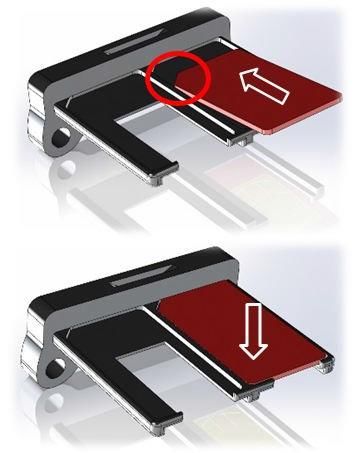
TABLE OF CONTENTS
Section 1:      Revisions and Approvals _____________________________________ 2
Section 2:      Introduction _______________________________________________ 5
Section 3:      DZMx Equipment ___________________________________________ 6
  Connectors ____________________________________________________________________ 6
Section 4:      DZMx Plus Specifications ____________________________________ 7
  Variants and Part Numbers _______________________________________________________ 7
  Dimensions ____________________________________________________________________ 7
  Electrical ______________________________________________________________________ 8
  Environmental/EMI Qualifications _________________________________________________ 9
Section 5:      Installation _______________________________________________ 10
  Mounting the DZMx ____________________________________________________________ 10
  DZMx Plus Wiring Guide ________________________________________________________ 11
  Installing a DZMx Plus Control Head _______________________________________________ 17
  DZMx Plus Antennas ____________________________________________________________ 17
Section 6:      Configuration _____________________________________________ 19
  Configuring the DZMx Plus_______________________________________________________ 19
  Audio Installation and Configuration ______________________________________________ 21
  Modem Configuration __________________________________________________________ 25
  Backlighting __________________________________________________________________ 29
  DZMx Plus WiFi________________________________________________________________ 32
  DZMx Plus Bluetooth™ __________________________________________________________ 33
  DZMx Tracking ________________________________________________________________ 35
  DZMx Plus Inputs and Outputs ___________________________________________________ 43
  Configuring DZMx PlusData _______________________________________________________ 46
  DZMx Plus Data Logging _________________________________________________________ 49
  DZMx Plus Email Outbox ________________________________________________________ 51
  Recording and Transmitting Maintenance Data ______________________________________ 51
Section 7:      DZMx Plus Applications ____________________________________ 53
  DZMx Plus Applications and Licences ______________________________________________ 53
  DZMx Plus Applications _________________________________________________________ 53
Section 8:      Maintenance, Diagnostics and Support ________________________ 54
  Firmware Upgrades ____________________________________________________________ 54

MAN_DZ7_001 Rev 1.1 Flightcell® DZMx Plus Installation Manual                  Page 3 of 61
Effective Date: 28 Jun 2021
Diagnostics ___________________________________________________________________ 55
  Flightcell Remote Assistance _____________________________________________________ 56
Section 9:      Documentation and Information ______________________________ 58
  Contact Details ________________________________________________________________ 58
  Warranty_____________________________________________________________________ 58
Appendix 1: Connector Kits & Associated Parts ___________________________ 60

MAN_DZ7_001 Rev 1.1 Flightcell® DZMx Plus Installation Manual                 Page 4 of 61
Effective Date: 28 Jun 2021
Section 2: Introduction
This manual provides information on the installation and configuration of the DZP_07-
xxx-xxxx Flightcell DZMx Plus.

MAN_DZ7_001 Rev 1.1 Flightcell® DZMx Plus Installation Manual                  Page 5 of 61
Effective Date: 28 Jun 2021

Section 3: DZMx Equipment
The DZMx Plus should be inspected when unpacked to check for any visible damage or
missing components.

Connectors
Connector kits are supplied with the DZMx Plus Transceiver DZP_07-xxx-xxxx and the
DZMx Plus Control Head DZP_05-002 including Bluetooth and WiFi antennas. The content
of the connector kits depends on the version of the DZMx Plus. Optional extras based on the
unit dash number and customer requirements will be at additional cost.
Details of the connector kit contents are provided in Appendix 1.

MAN_DZ7_001 Rev 1.1 Flightcell® DZMx Plus Installation Manual                     Page 6 of 61
Effective Date: 28 Jun 2021
Section 4: DZMx Plus Specifications
Variants and Part Numbers
The DZMx Plus can be built with a range of hardware options.
The DZMx part number is DZP_07. The 3 - 7 digit dash number immediately following DZP_07-
xxx-xxxx designates the variant of the DZMx Plus.
The available variants may change from time to time. The options available to build up the
different variants are:
    » Installed modems (see "Modem Configuration" on page 24 for a list of supported mode
          ms)

    » Additional circuit cards
    » Second ethernet
    » ARINC 429
    » Input expansion card

Dimensions

                                                                   DZMx Plus Control Head
 Dimension                    DZMx Plus
                                                                   DZUS mount
 Faceplate Width               N/A                                 146mm

 Extrusion Width               N/A                                 126mm

 Faceplate Height              N/A                                 57mm

 Extrusion Height              N/A                                 54mm

 Depth                         N/A                                 23mm

 Weight                       1.6kg (depending on configuration)   200 grams

 Length                       240mm                                N/A

 Width                        58mm                                 146mm

 Height                       188mm                                57mm

MAN_DZ7_001 Rev 1.1 Flightcell® DZMx Plus Installation Manual                           Page 7 of 61
Effective Date: 28 Jun 2021
Electrical
DZMx PLUS MAIN TRANSCEIVER MODULE
Part/Item Parameter Value
Power Input Voltage 12-32VDC
Power Supply Current Up to 1.5A @28VDC
ICS to DZM Audio Input Levels 20mVrms to 1.15Vrms, adjustable
775mVrms to 1.15RMS nominal
Input Impedance 600Ω
Microphone bias voltage 12V via 2.2kΩ
DZM to ICS Audio Output levels Up to 5Vrms, adjustable
775mVRMS nominal
Output Impedance 150Ω
Antenna bias voltage 5V
GPS
Antenna current Up to 100mA
Sensitivity -162dBm (with Flightcell Antenna)
Time to first fix 26s
Tx power (dBm) 17.3
Antenna gain (dBi) 2.6
WiFi
Total power (dBm) 19.9
Total power (mW) 97.7
Tx power (dBm) 10
Antenna gain (dBi) 2.6
Bluetooth
Total power (dBm) 12.6
Total power (mW) 18.2
RF Frequency Range 1616 MHz to 1625.5 MHz
Tx power (max) 7W
Satellite Antenna gain (dBi) 3
Iridium RF RX Sensitivity -118 dBm
Max Cable Loss 3 dB
Antenna impedance 50 Ω
USER INTERFACE
Power switch Momentary action switch PWR on/off with backlight
LEDs Transceiver Status Indicator x3
MAN_DZ7_001 Rev 1.1 Flightcell® DZMx Plus Installation Manual Page 8 of 61
Effective Date: 28 Jun 2021CONTROL HEAD SPECIFICATION
Part/Item Parameter Value
Input Voltage 12-32VDC
Power Supply Current Up to 1A @ 28VDC
Serial data interface between Control
Data connection RS485 full duplex
Head and DZMx Plus
User-configurable fixed level or
controlled from an external lighting
Input Control
dimmer. 0-28VDC or user-
Backlighting configurable response
Green 540nm. Designed for NVIS B
Colour
compliance
USER INTERFACE
Keypad 16 Button Keypad
LCD Display LCD backlit monochrome
Environmental/EMI Qualifications
The DZMx Plus is designed against RTCA DO-160G. Test results are pending.
Details of the DO-160G compliance will be provided in the DZMx Plus Declaration of Design
and Performance (DDP) document which is pending.
DO-160G test reports shall also be available on request from tech@flightcell.com.
MAN_DZ7_001 Rev 1.1 Flightcell® DZMx Plus Installation Manual Page 9 of 61
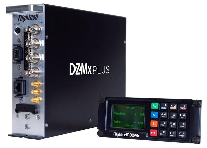
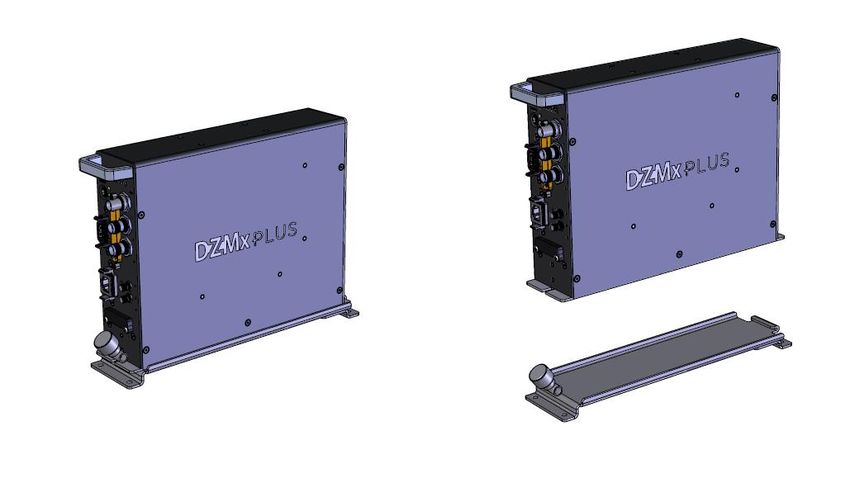
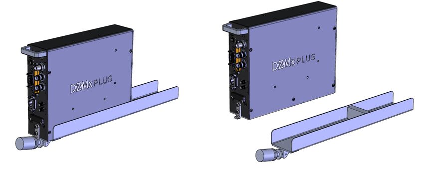
Effective Date: 28 Jun 2021Section 5: Installation DZMx Plus Mechanical Assembly ARINC 600 Tray DZMx Plus Mechanical Assembly Standard Tray Mounting the DZMx The DZMx Plus Control Head should be mounted where the flight crew or radio operator have a clear view of the display and can easily use the keypad. If the DZMx Plus Control Head is installed in the pedestal, for ease of use, it is preferable to install it as near to the front of the pedestal as possible. The DZMx Plus LCD is designed for optimum readability when viewed at angles between 60° above the display to 20° below. Avoid mounting the unit where the display will be viewed at an oblique angle, as it may not be clearly readable. It is preferable to mount the DZMx Plus to minimise sunlight shining on the display. MAN_DZ7_001 Rev 1.1 Flightcell® DZMx Plus Installation Manual Page 10 of 61 Effective Date: 28 Jun 2021
Mechanical drawings showing dimensions and mounting details are available on the
Flightcell website www.flightcell.com/resources
CAD solid model files are available on request from Flightcell International. Contact
tech@flightcell.com for more information.

DZMx Plus Wiring Guide
Wiring diagrams for the Flightcell DZMx Plus Transceiver and Control Head are available
on the Flightcell website www.flightcell.com/resources

Necessary Installations
The following are essential parts of the DZMx Plus installation:
    » Power Supply
    » DZMx Antennas
    » SIM Cards

Power Supply
The DZMx Plus unit and other components require aircraft DC power. Operating range is 12-
32VDC. It is recommended that the DZMx Plus be connected to the emergency (primary)
power bus on the aircraft. This is to ensure successful operation of tracking (including
engine start/stop data) and emergency calls.
When operating on a nominal 28V supply circuit breakers or fuses of the following rating
should be used between DZMx Plus system components and the power supply:
    » A 4-amp circuit breaker/fuse is recommended to protect the DZMx Plus system
    » A 1-amp circuit breaker/fuse is recommended to protect an external modem (Iridium
         or cellular) module, if installed

    » A 1-amp circuit breaker/fuse is recommended to protect a Flightcell Iridium phone
         cradle, if installed

    » A 1-amp circuit breaker/fuse is recommended to protect the DZMx Plus Control
         Head
If combining two or more circuits on a single circuit breaker a 4-amp circuit breaker/fuse is
recommended.

Fabricating Wiring Harnesses
All wiring should be carried out with aviation specification fireproof cable.
Screened cable should be used where indicated in the wiring diagrams. Where cable screen
connections are not explicitly shown, they should be left unterminated.
The following minimum wiring specification is recommended:
    » Power supply - 22 AWG stranded (0.325mm2)
    » Other cabling - 24 AWG stranded (0.205mm2).
It is recommended that enough slack be left in the main cable to enable the DZMx Plus
to be partially removed from the aircraft panel for service or to exchange the Iridium and/or
cellular SIM card.

MAN_DZ7_001 Rev 1.1 Flightcell® DZMx Plus Installation Manual                         Page 11 of 61
Effective Date: 28 Jun 2021
Grounding and Shielding Terminations
The DZMx Plus Transceiver chassis ground connection is on the main unit’s primary
connector. It does not have a DZUS connection.
If the DZMx Plus Control Head is mounted in a DZUS rack, the housing is grounded to the
DZUS rails via the DZUS connectors and contact between the front panel metalwork and the
DZUS rails.
Installing Data Ports
The DZMx Plus has several data connections wired off the main connector:
» RS232 – available for serial data connections to legacy devices and as a debug port.
» RS422/RS485 – used for serial data connections, and connection to one or more
DZMx Plus Control Heads.
» Two additional data connections are available as options, and these are wired off
the main connector.
» ARINC429 – used to send and receive over the aircraft ARINC429 data bus.
» Second Ethernet – used to provide a second ethernet connection.
Connector Pinouts
Wiring diagrams for the Flightcell DZMx Plus Transceiver and DZMx Plus Control Head ar e
available on the Flightcell website www.flightcell.com/resources
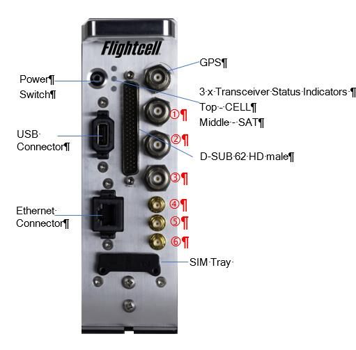
Refer to the figure below for the layout of the DZMx Plus Transceiver front plate.
MAN_DZ7_001 Rev 1.1 Flightcell® DZMx Plus Installation Manual Page 12 of 61
Effective Date: 28 Jun 2021CONNECTORS
Main Connector: D-SUB 62 HD male
Ethernet
USB
Antenna Connectors: GPS: BNC
SAT: TNC
CELL:TNC
SAT:TNC
WiFi: SMA
Bluetooth: SMA
ADS-B: SMA
OTHER
Power switch Momentary Action PWR On/Off
LEDs Transceiver Status Indicator x3
GREEN – Good Signal
AMBER – Medium Signal
RED – Bad Signal
OFF – No Signal
SIM TRAY Transceivers 1 and 2
DZMx Plus Main Connector D-SUB62
Pin No Connector Direction Notes
1 POWER GROUND Ground
2 AUDIO FROM DZM2 HI Output HI audio output to ICS 2
3 AUDIO FROM DZM2 LO Output LO audio output to ICS 2
4 AUDIO FROM DZM1 HI Output HI audio output to ICS 1
5 AUDIO FROM DZM1 LO Output LO audio output to ICS 1
6 NC
7 RS485 Rx+ Input
8 USB ID OTG I/O
9 AUX DATA GND Ground
10 GND Ground
11 GND Ground
12 RH_KEY Input
13 SPARE SHIELD Ground
MAN_DZ7_001 Rev 1.1 Flightcell® DZMx Plus Installation Manual Page 13 of 61
Effective Date: 28 Jun 2021DZMx Plus Main Connector D-SUB62 Pin No Connector Direction Notes 14 POWER GROUND Ground 15 OUTPUT 1A Output Isolated output 1 Terminal A 16 OUTPUT 1B Output Isolated output 1 Terminal B 17 OUTPUT 2A Output Isolated output 2 Terminal A 18 OUTPUT 2B Output Isolated output 2 Terminal B 19 NC 20 GENERAL PURPOSE INPUT 1 Input 21 DC SUPPLY POSITIVE Power 22 POWER GROUND Ground 23 USB GND OTG Ground 24 USB D+ OTG I/O 25 USB VBUS OTG Power 26 AUDIO TO AUX TXCVR HI Output 27 AUDIO TO AUX TXCVR LO Output 28 NC 29 RS485 Rx- Input 30 SPARE SHIELD Ground 31 POWER GROUND Ground 32 SPARE SHIELD Ground 33 GPIO1 I/O Reserved for Optional Capabilities 34 GPIO2 I/O Reserved for Optional Capabilities 35 POWER GROUND Ground 36 POWER GROUND Ground 37 AUX DATA RX Output 38 MIC TO DZMx 2 HI Input Unbiased/biased (configurable) 39 MIC TO DZMx 2 LO Input Return for audio input from ICS 2 40 GPIO5 I/O Reserved for Optional Capabilities 41 GPIO6 I/O Reserved for Optional Capabilities 42 DC SUPPLY POSITIVE Power 43 CHASSIS GND Ground Internally connected to DZMx Chassis 44 USB D- OTG I/O 45 AUDIO FROM AUX TXCVR HI Input 46 AUDIO FROM AUX TXCVR LO Input 47 MIC TO DZMx 1 HI Input Unbiased/biased (configurable) MAN_DZ7_001 Rev 1.1 Flightcell® DZMx Plus Installation Manual Page 14 of 61 Effective Date: 28 Jun 2021
DZMx Plus Main Connector D-SUB62
Pin No        Connector                                 Direction Notes
48           RS485 Tx+                                  Output
49           MIC TO DZMx 1 LO                           Input     Return for audio input from ICS 1
50           RS485 Tx-                                  Output
51           AUX DATA TX                                Input
52           NC
53           GPIO3                                      I/O       Reserved for Optional Capabilities
54           GPIO4                                      I/O       Reserved for Optional Capabilities
55           GPIO9                                      I/O       Reserved for Optional Capabilities
56           GPIO8                                      I/O       Reserved for Optional Capabilities
57           GPIO7                                      I/O       Reserved for Optional Capabilities
58           GENERAL PURPOSE INPUT 5 Input
59           GENERAL PURPOSE INPUT 4 Input
60           GENERAL PURPOSE INPUT 3 Input
61           GENERAL PURPOSE INPUT 2 Input
62           DC SUPPLY POSITIVE                         Power
D62 shell CHASSIS GND                                   Ground

  MAN_DZ7_001 Rev 1.1 Flightcell® DZMx Plus Installation Manual                              Page 15 of 61
  Effective Date: 28 Jun 2021
DZMx Keypad References
Most keys on the DZMx Plus Control Head keypad have more than one function. The
following table outlines how the DZMx Plus Control Head keys are referenced throughout
the Installation Manual.
 Icon         Manual Reference            Icon         Manual Reference

              CALL                                     5, SPD2

              END                                      6, RIGHT, SPD3

              A                                        7, MSG

              B                                        8, DOWN, DIR

              1, MARK                                  9, MODE

              2, UP, A.R.M., ALERT                     0, +, MENU

              3, EMER                                  *, BACK

              4, LEFT, SPD1                            #, ENTER, POWER

Navigating the Menus
The keypad is used to access the menu system:
   •  Press MENU. If the DZMx is on a phone call, press and hold MENU to access the
      menus.
    •    Use the UP and DOWN arrow keys to navigate between the menu options.
    •    Use the LEFT and RIGHT arrow keys to scroll left or right, to increase, decrease or
         navigate menus.
    •    Press ENTER to select the highlighted item or to confirm a setting change.
    •    Press BACK to cancel a setting or to move back a menu level.
    •    Press END to cancel a setting change or to exit the menu and return to the main
         screen.
    •    Instructions will be provided throughout the Manual in the format MENU > Forms
         >Form Entry etc

MAN_DZ7_001 Rev 1.1 Flightcell® DZMx Plus Installation Manual                         Page 16 of 61
Effective Date: 28 Jun 2021
• The > indicates that you will need to scroll to a menu heading using the arrow keys.
• Menu headings are bolded. Select a heading, press the ENTER key then scroll to the
next menu heading.
Installing a DZMx Plus Control Head
A Flightcell DZMx Plus Control Head is a remotely located control panel for the DZMx Plus,
with a display and keypad. One or two Control Heads may be installed to provide other crew
or mission specialists with full remote control of the DZMx Plus.
Wiring the Control Head
The Control head connects to the DZMx Plus transceiver using the RS485 serial data
connection.
Control Heads require a 12-32VDC power supply. Two additional connections are a ground
connection to the chassis, and a lighting input for external lighting control. Backlighting of the
Control Heads can be configured individually.
Wiring diagrams for the Flightcell DZMx Plus Transceiver and DZMx Plus Control Head ar e
available on the Flightcell website at www.flightcell.com/resources
Configuring the DZMx Plus for a Control Head
First, the DZMx Plus needs to be configured to recognise the Control Heads:
1 . Press MENU > Hardware Config > Head B Enable. Select On to enable, or Off to
disable the Control Head.
2. Press ENTER to save the setting.
Configuring the Control Head
The Control Head now needs to be allocated a head ID so that the DZMx Plus can identify it.
1 . Press and hold the BACK key on the Control Head for 2 seconds, then release. Scroll
down to Advanced press ENTER.
2. Head ID will be displayed. Use the RIGHT and LEFT arrow keys to select the
correct head ID (Head B), then press the END key twice to save and return to the
main screen.
DZMx Plus Antennas
The following antennas are not supplied with the DZMx Plus but can be purchased at an
extra cost:
» Single Iridium modem: Use a Flightcell dual Iridium/GPS antenna part number:
ANP_00043.
» Dual Iridium modems: Use a Flightcell Iridium/GPS antenna, P/N ANP_00043, and
a single Iridium antenna, ANP_00045.
» Single cellular modem: Use a Flightcell cellular antenna, P/N ANP_00033.
» Dual cellular modems: Use a Flightcell dual cellular antenna, P/N ANP_00041.
MAN_DZ7_001 Rev 1.1 Flightcell® DZMx Plus Installation Manual Page 17 of 61
Effective Date: 28 Jun 2021Installation of Iridium and GPS Antennas
Installation drawings for the above antennas are available on the Flightcell website
www.flightcell.com/resources.
The Flightcell Iridium/GPS antenna and Iridium antenna should be installed on the top of
the aircraft where they will have an unrestricted view of the sky, mounted as close to
horizontal as possible. The following should be considered when determining a mounting
location:
» Maintain good separation from other antennas. Preferred separation is 750mm from
L-band (GPS), TCAS or transponder antennas, but a lesser separation can be
applied if there is limited space on the aircraft.
» On a helicopter, the antenna can be installed below the rotor blades, but avoid
installing it close to the rotor hub, as the hub and inner rotor can block the antenna’s
view of the sky.
» Keep coax cable lengths short to minimize attenuation of transmit and receive
signals.
Installation of Cellular Antennas
A Flightcell cellular antenna should preferably be installed on the underside of the aircraft
to provide best connection to the cellular network. Typical location is below the cockpit to
minimise antenna cable length. The minimum recommended separation between the cell
antenna and other antennas is 600mm.
Guidelines for Antenna Cables
Iridium antenna cables must be selected to keep signal loss within accepted levels. Total
signal loss on the Iridium connection between the DZMx P l u s or Iridium phone cradle
and the antenna should not exceed 3dB at 1645MHz.
The maximum recommended length for different common antenna cable types is:
Cable Length Cable Specification
Up to 3m RG58C/U or RG400
Up to 6.5m LMR200 or RG142A/U-
Up to 8m 9006 cellfoil
RG213
Up to 17m LMR400
Up to 26m LMR600
Antenna connectors on the DZMx Plus and Flightcell antennas (as well as the supplied
mating connectors) are colour coded to reduce installation errors, as follows:
Antenna Type Colour
Iridium Red
Cellular Green
GPS Blue
MAN_DZ7_001 Rev 1.1 Flightcell® DZMx Plus Installation Manual Page 18 of 61
Effective Date: 28 Jun 2021Section 6: Configuration
Accessing Installation and Configuration Settings
Many of the DZMx Plus configuration settings are hidden during normal operation. To
access these settings, the Installer Menu needs to be activated. The Installer Menu will
remain active until the DZMx Plus is next powered off. If a menu item mentioned in this
manual cannot be found ensure that the Installer Menu has been activated.
Configuring the DZMx Plus
The DZMx Plus can be configured using the DZMx Plus Control Head (keypad and display)
or using DZMx Connect. Most settings are available on both interfaces.
Use the DZMx Plus Control Head when real-time feedback on the configuration is preferred:
» Adjusting audio settings
» Configuring the general-purpose Inputs.
However, it is recommended that DZMx Connect is used to configure and to change settings
as it is faster and provides a more intuitive interface than the DZMx Plus Control Head
front panel.
Configuring using DZMx Connect
DZMx Connect can be used to configure, change settings, edit the DZMx Plus phonebook
and message library. The DZMx Connect is available as an iOS and Android application
(available from the respective app stores), or as a browser application on a PC.
There are three ways to use DZMx Connect:
Hardwired Computer Connection
1. Connect a computer to the DZMx Ethernet port.
2. Power up the DZMx Plus and wait for it to fully initialise.
3. Open a web browser, type in 192.168.4.1 in the address bar and press enter.
The home screen of DZMx Connect will open in the browser.
4. If the DZMx Plus has been allocated a fixed IP address, or the DZMx Plus is
set up as a DHCP client, then it is necessary to enter this address (this could
be, for example, 192.168.4.100). This IP address can be determined by
selecting the MENU key. Scroll down to Diagnostics Menu > About DZMx >
press ENTER then select the END key to return to the main screen.
Wireless Laptop or Personal Computer (PC) Connection
With the DZMx running.
1. Check that WiFi is enabled. Look for a WiFi icon located at the top right-
hand side of the DZMx Plus Control Head display. If the WiFi icon is not
present it can be checked and enabled in one of three ways:
a. Press and hold the MODE key until “Enabling WiFi and Bluetooth” is
displayed on the screen. WiFi can also be disabled by pressing the
MODE key.
MAN_DZ7_001 Rev 1.1 Flightcell® DZMx Plus Installation Manual Page 19 of 61
Effective Date: 28 Jun 2021b. Using the Control Head keypad, select MENU, scroll down to Hardware
Config > Wireless and Networks > press ENTER and when WiFi Enable
is displayed press ENTER then Yes or No. Select END to return to the
main screen.
c. Connect a PC or laptop to the DZMx Plus via an Ethernet cable. Type
192.168.4.1 into a web browser and navigate to Connectivity > WiFi and
toggle the switch to ON.
2. To connect via Wi-Fi,
a. Open the Wi-Fi control panel on the laptop, select the Wi-Fi address for
the DZMx Plus, then enter the password (the default password is
flightcell).
b. Open a web browser on the laptop and type in 192.168.2.1 then press
ENTER; the home screen of DZMx Connect will open within the
browser.
Click here to watch a short video explaining the DZMx Connect capabilities (demonstrated on
the app version).
Smart Device Connection
1. In the smart device settings connect to the DZMx Plus Wi-Fi using default SSID
DZMx Plus Wi-Fi, default password: flightcell (all lower case).
2. Open DZMx Connect. The initial screen is a discovery screen and the DZMx Plus
should be discovered automatically. The DISCOVER button is only required if the
process needs to be repeated.
3. If the DZMx IP address has been manually configured, it will be necessary to enter
this IP address in the browser address bar. After the first use of a custom IP address,
the app will remember the address in the Stored Devices list.
4. Click on the discovered DZMx Plus unit to open navigation and settings options.
Permission levels
Permission levels allow users to have control over how the DZMx is configured. Three levels
or roles with individually configurable passwords are available within DZMx Connect.
To access Permissions:
1 . Select LOGIN at the top of the screen. The login screen will open.
2. Select Installer or Administrator from the dropdown list to the right of Authenticate as:
3. Enter the related PIN number from the list below.
PIN
Role Responsibility
number
The installer can edit all settings and hardware
Installer 2468
options.
Access to all application features and
Administrator 2580 configuration, unable to access hardware
configurations.
MAN_DZ7_001 Rev 1.1 Flightcell® DZMx Plus Installation Manual Page 20 of 61
Effective Date: 28 Jun 2021Note: Passwords can be changed by the Installer and the Administrator in “Settings”.
An Administrator or Installer can revert to the original Operator status.
The default password 1234 cannot be configured.
To access Permissions using DZMx Plus keypad:
Select MENU > Hardware Config > Installer Menu Enable > press ENTER
Enter the PIN number and press ENTER.
Changing the Installer Password
The installer password can be changed as required:
1. On the DZMx Plus Control Head, select MENU > Hardware Config > press
ENTER > Change Installer Passwd > press ENTER > Enter Pin. Enter a new
4-digit number. Select END to save and return to the main screen.
2. Using DZMx Connect, go to Settings > Preferences > Access Management.
Enter the new PIN number and select DONE.
Note: It is important to record the password. If the password is forgotten, it will be
necessary to reset the DZMx to the factory settings before the password protected functions
can be used again.
Audio Installation and Configuration
The DZMx Plus supports the following audio services:
» Telephony over the Iridium and cellular networks (depending on the modems
installed in the DZMx).
» Iridium PTT, a Push-to-Talk service using the Iridium network to provide one-to-
many PTT calling.
» Telephony over a mobile phone connected to the DZMx Bluetooth service.
Connection to the Aircraft Audio System
Audio from the above services is connected into the aircraft audio system or incident
command system (ICS) to enable aircrew, mission crew or passengers to use these
connections.
The DZMx Plus can be connected to the aircraft audio system or ICS in several ways,
depending on the aircraft configuration and type of operation.
It is recommended that audio from the DZMx Plus is connected to spare radio positions on
the ICS if possible.
Modem connections to the ICS are configured using DZMx Connect. Go to Settings > Audio
> Modems.
Single or Dual ICS Connections
The DZMx Plus supports one or two connections to the audio panel/ICS, ICS1 and ICS2.
MAN_DZ7_001 Rev 1.1 Flightcell® DZMx Plus Installation Manual Page 21 of 61
Effective Date: 28 Jun 2021The dual ICS connections may be used to allow the DZMx Plus to be connected to two
different audio panels on the aircraft, or to allow different audio connections to be used
simultaneously.
Mirroring Audio on Dual ICS Connections
If the DZMx Plus has connections to two audio panels but it is desirable to have the
same audio mirrored to both, select Mirror Audio to ICS2. Toggle slider to activate and
select DONE
Providing for Modems to be Connected to Separate ICS Connections
The two ICS connections may be used to allow the DZMx Plus modems or connected
Bluetooth device to connect to separate ICS channels, allowing separate calls to occur
on the separate respective ICS channels.
Typically, this is used where ICS1 and ICS2 are connected to different audio positions
on the ICS.
Each of the modems and Bluetooth device may be allocated to either ICS1 or ICS2.
Simultaneous Calls
DZMx installations with more than one modem can make two calls simultaneously.
Making and receiving the first call works the same way as described above. However,
to make the second call, a long press is required to use the speed dial, phonebook, or
menu keys.
Note: While on two calls, both parties can hear you, but they are unable to hear each
other.
Call Priority
A modem which has been given priority will automatically mute all other calls when it
makes or receives a call. When a priority call has ended, it automatically unmutes any
other call. This can be particularly useful if a call on a modem is vital to vehicle aircraft
operations. By default, call priority is off, however it can be enabled using the "Call
Priority" setting for each modem in DZMx Connect. Go to Settings > Audio > Modems.
This option can be found in the settings under the audio section. This setting is
particularly useful for simultaneous calls on a single ICS channel.
Audio from the DZMx to the ICS
Audio from the DZMx Plus is connected direct to the ICS input, and its levels adjusted using
the DZMx Plus audio menu.
Audio from the ICS to the DZMx Plus (microphone installation)
The DZMx Plus can be installed in aircraft systems with either high impedance or low
impedance microphones. Most (but not all) civil aircraft operate high impedance (electret)
microphone systems. Refer to www.flightcell.com/resources for wiring diagrams for the
microphone connections.
MAN_DZ7_001 Rev 1.1 Flightcell® DZMx Plus Installation Manual Page 22 of 61
Effective Date: 28 Jun 2021Low Impedance Microphones
When installing the DZMx Plus with an ICS that uses low impedance mics, the DZMx
Plus must be connected to a line level Radio/Comms port. If a line-level port is not
available and the DZMx Plus is to be connected direct to the mic line, then a tactical
radio adaptor will be needed to match impedances. Options include the NAT AA34-
300, Jupiter JA34-001 or PS Engineering 200-002-0002.
High Impedance Microphones
There are several options for connecting the DZMx Plus into an audio panel/ICS with
high impedance microphones. The way in which the DZMx Plus is connected will
depend on your system configuration and operational requirements.
As the Iridium satellite phone and cell phone are both full duplex, it is preferable to use
the DZMx Plus on a hot mic connection, rather than PTT (keyed).
The DZMx Plus will typically be installed in one of the following ways:
1. Connecting Directly to a Headset Microphone Line
The MIC lines are spliced to one or more headset microphone inputs on the
audio panel. As these microphone inputs have mic bias provided by the audio
panel, the DZMx Plus should have mic bias disabled.
The way this is configured will depend on how many headsets are to have
access to the DZMx Plus:
» If only the pilot is to use the DZMx Plus, its MIC TO DZMx 1 HI/LO lines are
connected only to the pilot’s microphone line.
» If both pilot and co-pilot are to use the DZMx Plus, the MIC lines are connected to
the pilot microphone line and the MIC lines are connected to the co-pilot
microphone line.
» If more than two microphones need to have access to the DZMx Plus, an external
switch is required to select the active microphone input.
2. Connecting to a Cell Phone Port on the Audio Panel
The DZMx Plus MIC line can be connected to the cell phone port on the audio panel.
3. Connecting to a Spare Radio Position on the Audio Panel
On aircraft with separate audio control panels at each crew position, this option
enables crew to use the DZMx Plus and connected phones individually on demand.
In this case it may be necessary to provide mic bias.
Configuring Microphone Bias
In some aircraft with high impedance headsets, where the mic line is connected
direct to the DZMx Plus, it is necessary to provide bias power to energise the
headset microphone.
To activate mic bias power to the MIC line:
» Activate using the DZMx Plus Control Head. Select MENU > Audio > press
ENTER > ICS > press ENTER > Mic Bias > press ENTER >select Off or On.
Select END to return to the main screen.
MAN_DZ7_001 Rev 1.1 Flightcell® DZMx Plus Installation Manual Page 23 of 61
Effective Date: 28 Jun 2021» Activate using DZMx Connect. Go to Settings > Audio > ICS1 or ICS2. Select
DONE when completed.
Configuring Side Tone
Side tone is normally provided by the aircraft audio panel or ICS, but in some
installations may not be available. Side tone can be supplied by the DZMx Plus if
required.
This can be configured using the:
» DZMx Plus Control Head. Select MENU > Audio > press ENTER > ICS > press
ENTER -`> Mic Bias > press ENTER > select Off or On. Select END to return to
the main screen.
» DZMx Connect app. Go to Settings > Audio > ICS1 or ICS2. Toggle on Side
Tone.
» Select Off to disable, When on Call to enable only during a call, or Always On to
leave active all the time. Select OK once you have selected then select DONE.
Configuring Notification Tones
Notification tones are used to notify the crew of specific events. Notification tones can
be enabled or disabled in the audio menu. Notification tones include:
» Keypad tones.
» Message queue full, which sounds when the tracking message queue is full.
» Warnings, which notify when there is an issue; in this case a popup will show the
details of the issue.
» Incoming or outgoing Bluetooth call.
Adjusting Audio Volume
Audio levels can be adjusted using DZMx Connect or the DZMx Plus Control Head menu,
however as there is a short lag when using the DZMx Connect, it is recommended that audio
levels are adjusted using the DZMx Plus Control Head menu.
1 . To adjust audio volumes to the ICS (EAR):
» Set up a call to another party over the satellite or cellular link as appropriate using
Select MENU > Audio > ICS > Ear> press ENTER. Use the LEFT and RIGHT
keys to adjust the audio volume to the preferred level. Select END to save and
return to the main screen.
2. To adjust audio volumes from the ICS to the DZMx Plus (MIC):
» Set up a call to another party over the satellite or cellular link as appropriate.
» Select MENU > Audio > ICS > Mic and use the LEFT and RIGHT keys to adjust
the audio volume to the preferred level. Select END to save and return to the main
screen.
MAN_DZ7_001 Rev 1.1 Flightcell® DZMx Plus Installation Manual Page 24 of 61
Effective Date: 28 Jun 2021Iridium Push-To-Talk (PTT)
Iridium PTT is a licensed feature. If you wish to use Iridium PTT, you must subscribe to the
PTT service through your Iridium Service Provider and purchase a licence from Flightcell by
contacting orders@flightcell.com.
» To enable and configure your DZMx Plus for PTT using DZMx Connect. Go to
Settings > Modem > Internal Sat modems.
» If you wish to have the DZMx Plus start up in PTT mode, activate Start PTT on Boot.
Select DONE when finished.
» If the PTT talkgroups are changed by your Iridium Service Provider, it is
recommended to update talk groups using the DZMx Plus Control Head. Select
MENU > PTT Talk Groups > Refresh Talk Groups.
Configuring the PTT Input
PTT calls can be triggered from the DZMx Plus keypad, but it is preferable to use a
PTT switch connected to a DZMx Plus Input.
Note: The Call Priority setting can be useful for automatically muting a PTT call
when making a call on another modem.
Modem Configuration
The DZMx Plus can be configured with up to three internal modems and one external modem
or satellite phone.
Cellular Modems
The following cellular modems may be installed in the DZMx Plus:
» A 4G (LTE) modem
» A 450 MHz modem.
Different countries or geographic areas use different cellular bands, due to international and
national radio frequency licensing agreements.
In Revision 3 DZMx, the cell modem supports most of the bands to for all countries in the
world.
In Revision 4 DZMx, four different modem versions are used for different geographic regions.
The four modem options are:
» Europe
» Asia/Pacific and South America (APAC)
» Americas and Band 14 (North America, including the US Public Safety Band, band
14)
» Japan.
MAN_DZ7_001 Rev 1.1 Flightcell® DZMx Plus Installation Manual Page 25 of 61
Effective Date: 28 Jun 2021Note: There is considerable overlap in the bands offered by the different modem versions, so
some modems can be used in more than one geographic area, with some reduction in the
bands available.
When ordering the DZMx Plus, it is essential that the version with the correct regional modem
is ordered. Please contact tech@flightcell.com for more information on the appropriate
modem for your operational area.
Iridium Modems
The following satellite modems may be installed in the DZMx Plus:
» One or two internal Flightcell Iridium 9523 modems.
» An Iridium 9603 modem (used for Short Burst Data only).
External Modems and Phones
One external modem or satellite phone can be connected to the DZMx Plus via its RS232
serial port:
» A Flightcell Iridium Modem.
» An Iridium handset installed in a Flightcell Iridium Phone Cradle; these may be:
▪ Iridium 9555.
▪ Iridium Extreme.
The modem and the phone handsets provide the same functions (except for Iridium PTT) as
the internal Iridium modem, providing phone calling, messaging, and data. These functions
are all controlled by the DZMx Plus, so it is not necessary to use the phone keypad.
The external Iridium devices do not support Iridium PTT; this can only be provided by an
internal Iridium 9523 modem.
Activating Modems
» Your DZMx Plus will normally be configured for the installed internal modems
prior to shipment.
» You may need to configure the DZMx Plus for an external device such as an
Iridium modem or Iridium phone and cradle, if installed.
» The DZMx Plus can be configured for the installed and external modem
options using DZMx Connect. Go to Settings > Hardware.
» You will need to check the detailed configuration for each modem and
external device to ensure they are correctly configured for your operation.
SIM Cards
A SIM card is required for a DZMx Plus cellular modem.
SIM cards must be installed in the DZMx Plus for an internal Iridium 9523 if it is to be used
for phone calling and SMS messaging. A SIM card is not required for the Iridium 9523
modem if it is to be used only for Iridium PTT or for Iridium SBD.
A SIM card is not required for an Iridium 9603 (SBD only) modem.
The DZMx uses standard SIM cards, rather than the micro and nano versions.
MAN_DZ7_001 Rev 1.1 Flightcell® DZMx Plus Installation Manual Page 26 of 61
Effective Date: 28 Jun 2021SIM Slot Designation
Where the DZMx has an Iridium modem and cell modem installed.
» SIM 1 is allocated to the Satellite Iridium modem
» SIM 2 is allocated to the Cellular modem.
Note: Iridium and cellular cards can be used in both slots depending on the unit
configuration purchased.
Installing SIM cards
SIM cards are installed in the SIM card tray inserted in
the front of the DZMx Plus. To install SIM cards:
1. Undo the screws securing the SIM card tray
and remove the tray.
2. Preferably place the tray on the edge of a hard
surface such as a table or book.
3. Position the SIM card with the bevelled corner
(circled in drawing) forward and contacts
downward, then slide the front edge into the
recess in the front of the tray.
4. Tilt the card downward until it clicks into the groove in the tray.
5. Insert the tray into the slot on the front of the DZMx Plus and secure in place
with the two cap screws.
Note: Ensure that the SIM cards are in the correct slots, as they may be permanently
damaged if incorrectly installed.
AT&T SIM Cards
Not all AT&T SIM cards are compatible with non-AT&T devices. For troubleshooting
with AT&T SIM cards, visit the AT&T troubleshooting website
https://troubleshoot.att.com/devicetroubleshoot.
Iridium SIM cards supplied with your DZMx
DZMx Plus with Iridium modems are shipped with an unregistered Iridium SIM
installed, unless otherwise requested. This can be registered to your Iridium Service
Provider’s account when you are ready to activate your Iridium service.
To transfer the SIM card to your ISP, please contact Flightcell International at
orders@flightcell.com, advising the serial number of your DZMx Plus and the name of
your ISP.
Configuring Modems
The DZMx Plus is configured prior to shipment with default settings for the installed modems.
However, you may need to check and modify these settings.
This is done using DZMx Connect. Go to Settings > Modems.
MAN_DZ7_001 Rev 1.1 Flightcell® DZMx Plus Installation Manual Page 27 of 61
Effective Date: 28 Jun 2021Configure which modems are used to transmit tracking data
By default, tracking messages are enabled for all modems. If more than one Iridium
device or more than one cell modem is installed, only one of each should be activated
for tracking.
If the internal Iridium 9523 modem is used for Iridium PTT, then the other Iridium
modem (9523 or 9603) or external Iridium device should be configured for tracking.
Configure Iridium or cellular voice calling capability
By default, voice calling is enabled for all modems, except for the Iridium 9603 modem,
which is used for SBD messaging only, and the 450 MHz cellular modem, which is for
data only.
Configure Iridium SBD Transmission
If your Iridium modem has been provisioned to send SBD messages to your chosen
tracking provider, then ensure SBD transmission is enabled for your Iridium device.
If you do not wish your device to send SBD messages, then disable SBD
transmission.
Configure the Iridium Service Centre
Most Iridium accounts use the standard Iridium Service Centre for handling Short
Message Network (SMS) messages. However, some Iridium Service Providers use
different Secure Server Networks (SSNs) e.g. Telstra and Pivotel in Australia.
If (No SMS) is displayed next to the Iridium modem's status message on the DZMx
Plus display, the service centre number is incorrectly set. The service centre number
can be selected:
» Use DZMx Connect. Go to Settings > Modem. Select Modem settings 1 and
insert the Call Forward Number and toggle Call Forwarding Enable on.
Select DONE.
» Use the DZMx Plus control head. Go to MENU > Hardware Config > Modem
Config > Iridium Modem 1 > Service Centre Number > and select the correct
option.
Configure the cellular APN
It is necessary to set the Access Point Name (APN) for the cellular modems to allow
the modem to use cellular data services. You will need to determine the APN for your
cellular provider. This is often but not always “Internet”.
Enable or disable data
Use this setting to enable or disable data services for the selected modem.
Data Roaming
If a cell modem is operated outside its home country, it is usually necessary to activate
data roaming to allow use of local cellular services.
MAN_DZ7_001 Rev 1.1 Flightcell® DZMx Plus Installation Manual Page 28 of 61
Effective Date: 28 Jun 2021Disabling Cell Modems
In some cases, it may be a requirement to disable cell modems for operational or
regulatory reasons.
The DZMx Plus may be configured so that:
» Cell modems are always enabled.
» Cell modems can be disabled via softkey – the modem can be disabled
manually on the DZMx Plus, using a long press on the A or B softkey
allocated to that modem.
» Cell modems are automatically disabled when the aircraft is in flight.
When a cell modem is disabled, all transmit and receive functions are completely
disabled.
These settings can be changed using DZMx Connect. Go to Settings > Modem > Cell
modems. Select one of the options from the drop down (Off, Disable Via Soft Key,
Disable When in Flight. Select OK. Select DONE when completed.
Note: When set to automatically disable in flight, the manual disable/enable key can
override the automatic option until the next take-off or landing.
Backlighting
The DZMx Plus Control Head has a backlit keypad and LCD display.
Backlighting can only be adjusted using the DZMx Plus menus or DZMx Connect.
Backlighting Options
The DZMx Plus Control Head can support variable lighting controlled from the aircraft
dimmer control. Aircraft without dimmer controls can manually set the brightness to Day and
Night levels. External lighting provides the user with the ability to dim or brighten the
display by adjusting the cockpit dimmer control. The Control Head uses the lighting control
input (pin 10) for its external lighting input.
» Day backlight is set at maximum brightness for the DZMx Control Head keypad
and display.
» Night backlight can be adjusted separately for the keypad and LCD display.
» A separate dimmer control can be used for each DZMx Plus Control Head.
» External lighting is only available if the DZMx Plus has been installed with external
lighting wiring.
Switching Backlight Modes
To switch modes between Day, Night and External Backlighting on the Control Head:
1 . Press and hold the * key for 2 seconds.
2. Scroll to the Backlight Mode.
3. Use the LEFT or RIGHT keys to change the setting.
4. Press the END key to exit to the main screen.
MAN_DZ7_001 Rev 1.1 Flightcell® DZMx Plus Installation Manual Page 29 of 61
Effective Date: 28 Jun 2021Altering Backlight Brightness Levels
Day and Night Modes
Backlight settings can be adjusted separately for the keypad and LCD display. To
configure backlight settings on the DZMx Plus Control Head for Day and Night
modes.
1. Press and hold the key for 2 seconds and then release.
2. Select the Day or Night setting.
3. Select Display Brightness or Keypad Brightness. The brightness level is
displayed within the brackets e.g. .
4. Use the LEFT key to decrease the brightness and the RIGHT key to increase
the brightness.
5. Press the END key to exit the lighting mode and save the setting and to exit
the menu.
External Lighting Mode
The minimum and maximum brightness levels can be set for the DZMx Plus
Control Head. The external lighting has two modes, which is determined by the
way you set the Ext Lighting Calib Low point. The external lighting options are:
Option 1: External lighting input controls night lighting and toggles Day/Night
mode. This requires setting the 'Low calib' point to a level higher than
the lowest input voltage (typically at the 'detent' on the dimmer control).
Turning the input below the 'detent' position switches the brightness to Day
mode.
Option 2: External lighting input controls night lighting only (no Day/Night mode
switch). This requires setting the 'Low calib' point at the minimum input
voltage.
To change the brightness options for the external lighting on the DZMx Plus Control
Head:
1. Press and hold the key for 2 seconds.
2. Scroll to Advanced > press ENTER > Ext Lighting Config Low > press
ENTER.
3. Adjust both the keypad and display brightness. Use the LEFT key to lower the
brightness and the RIGHT key to increase the brightness to match the cockpit
lighting levels.
4. Scroll to Input Calib. > press ENTER.
5. Press the END key 3 times to save the settings and exit to the main screen.
To change the maximum brightness options for the external lighting on the DZMx Plus
Control Head:
1. Press and hold the key for 2 seconds.
2. Scroll to Advanced > Ext Lighting Config High > press ENTER.
MAN_DZ7_001 Rev 1.1 Flightcell® DZMx Plus Installation Manual Page 30 of 61
Effective Date: 28 Jun 20213. Adjust both the keypad and display brightness. Use the LEFT key to lower the
brightness and the RIGHT key to increase the brightness to match the cockpit
lighting levels. Scroll to Input Calib. >press ENTER
4. Press the END key 3 times to save the setting and exit to the main screen.
Checking Input Range
The Input Calib. options in the maximum and minimum brightness shows the raw input
values, which update each time the ENTER key is pressed. These values need to
be checked during installation to ensure that the hardware is functioning correctly.
MAN_DZ7_001 Rev 1.1 Flightcell® DZMx Plus Installation Manual Page 31 of 61
Effective Date: 28 Jun 2021The following requirements are necessary for proper set-up of the external lighting:
» The minimum position needs to have a smaller value than the maximum
position.
» A DZMx Plus Control Head will typically have a difference of around 900.
Note: It is recommended that the lighting control input should vary between 0V and
28V between minimum and maximum lighting respectively.
DZMx Plus WiFi
The DZMx Plus can be supplied with optional integrated WiFi components (designated by a
W at the end of the product’s part and dash number e.g.: DZP_07-xxx-xxW
DZMx Plus Wi-Fi is a licensed application; purchase of a Wi-Fi licence is required to activate
the Wi-Fi service on the DZMx Plus.
DZMx Plus Wi-Fi allows the DZMx Plus to act as an access point to connected devices,
enabling the DZMx Plus to be used to route DZMx Plus data connections to connected
devices, including:
» PCs
» Tablets
» Smartphones
» Medical devices
» Other specialised devices
» Provide WPA2 encryption security to wireless devices.
Starting WiFi
If the DZMx is WiFi capable and the Wi-Fi licence has been activated, the WiFi service is
active by default.
It is possible to toggle WiFi on and off from the front panel using a long press on the MODE
key.
When WiFi is enabled, a wireless icon will appear at the top right of the screen on the
front panel.
If it is necessary to disable WiFi so that it cannot be overridden by the flight crew, the MODE
key function can be disabled using DZMx Connect.
1 . Go to Settings > Preferences > Main Screen Options > Mode Button Function.
2. Select required option (Disabled, Toggle WiFi, Toggle Bluetooth, Toggle BT and WiFi).
3. Select Ok then DONE.
WiFi Settings
WiFi settings can be configured using DZMx Connect. Go to Connectivity >WiFi.
The following settings can be modified:
» Service Set Identifier (SSID).
MAN_DZ7_001 Rev 1.1 Flightcell® DZMx Plus Installation Manual Page 32 of 61
Effective Date: 28 Jun 2021» Passkey.
» Wireless Local Area Network (WLAN) channel.
» WiFi Dynamic Host Configuration Protocol (DHCP) Server settings.
DZMx Plus Bluetooth™
DZMx Plus Bluetooth is a built-in option that works with any DZMx Plus that has a DZP_07-
xxx-xxW part and dash number.
DZMx Plus Bluetooth is a licensed application; purchase of a Wi-Fi or Bluetooth licence is
required to activate Bluetooth on the DZMx Plus.
DZMx Plus Bluetooth provides the ability to pair a mobile device, such as mobile phone or
tablet, to the aircrafts Inter Communication System (ICS)/headset which is like the hands-free
operation in a motor vehicle.
Functionality includes:
» Making and receiving calls on a mobile device and talk via the ICS and headset.
» Listening to streaming media on a headset from a mobile device.
If Bluetooth menu options are not available, this functionality will need to be purchased and
then activated with a software key supplied by Flightcell International Ltd.
Enabling Bluetooth
Once Bluetooth is enabled, it is possible to toggle it on and off from the front panel or the
Control Head using a long press on the MODE key.
When Bluetooth is enabled, the Bluetooth icon will appear at the top right of the DZMx
Plus Control Head screen.
Bluetooth can be disabled in the DZMx Plus Control Head menu: Select MENU > Hardware
Config > Wireless and Networks > >Bluetooth Enable> select No or Yes > press ENTER to
save and press END to return to the main screen.
Pairing
1. Check that the Bluetooth icon is showing on the DZMx Plus display
2. Make the DZMx Bluetooth discoverable using the:
» DZMx Connect app menu. Go to Connectivity > Bluetooth. Ensure Bluetooth is
toggled On.
» DZMx Plus Control Head. Select MENU> Hardware Config > Wireless and Networks
> Blue Tooth Discoverable > Press ENTER and select No or Yes > press ENTER to
save and press END to return to the main screen.
3 . Enable Bluetooth on the mobile device settings and select the ‘DZMx Plus Bluetooth’
device.
4. A pairing notification message with a confirmation code will appear on the DZMx Plus
Control Head and the mobile device. Ensure they are the same number.
5. Press the ENTER key on the DZMx Plus Control Head, then select Pair on the mobile
device.
MAN_DZ7_001 Rev 1.1 Flightcell® DZMx Plus Installation Manual Page 33 of 61
Effective Date: 28 Jun 2021Connecting paired Bluetooth devices
The DZMx Plus may be configured to require devices to be connected manually each
time, or to automatically connect the last connected device.
» Use DZMx Connect. Go to Connectivity > Bluetooth. Toggle Discoverable ON and
or auto connect ON.
» Use the DZMx Plus Control Head. Select MENU > Hardware Config > Wireless
and Networks > Bluetooth Autoconnect > select No or Yes > press ENTER to
save and press END to return to the main screen.
Note: The auto-connect functionality may vary according to mobile devices and the level
of support provided by their operating systems.
A high degree of variability is present across Android devices, and they may need to be
connected manually.
Hands Free Calling
The DZMx Plus supports a Bluetooth audio Hands Free Profile (HFP). If a Bluetooth device is
connected in this mode and pairing has been successful, the DZMx Plus Control Head will
display a mobile phone icon in the top left corner of its display. If a user receives or initiates a
call on the paired mobile device, the audio will be routed to/from the ICS/Headset.
Media Streaming
The DZMx Plus supports an Advanced Audio Distribution Profile (A2DP). If a Bluetooth
device is connected and pairing has been successful, the DZMx Plus Control Head will
display a musical icon in the top left corner of its display. When the user starts audio playing
on the connected mobile device it will be audible through the ICS/Headset.
IMPORTANT NOTE RELATING TO DZMx Plus BLUETOOTH MODEM: To comply with FCC
requirements, the BT800 must not be co-located or operating in conjunction with any other antenna or
transmitter.
Federal Communication Commission Interference Statement
This equipment has been tested and found to comply with the limits for a Class B digital device,
pursuant to Part 15 of the FCC Rules. These limits are designed to provide reasonable protection
against harmful interference in a residential installation. This equipment generates, uses, and can
radiate radio frequency energy and, if not installed and used in accordance with the instructions, may
cause harmful interference to radio communications. However, there is no guarantee that interference
will not occur in a particular installation. If this equipment does cause harmful interference to radio or
television reception, which can be determined by turning the equipment off and on, the user is
encouraged to try to correct the interference by one of the following measures:
1. Reorient or relocate the receiving antenna.
2. Increase the separation between the equipment and receiver.
3. Connect the equipment into an outlet on a circuit different from that to which the receiver is
connected.
4. Consult the dealer or an experienced radio/TV technician for help.
FCC Caution: Any changes or modifications not expressly approved by the party responsible for
compliance could void the user's authority to operate this equipment.
This device complies with Part 15 of the FCC Rules. Operation is subject to the following two
conditions: (1) This device may not cause harmful interference, and (2) this device must accept any
interference received, including interference that may cause undesired operation.
MAN_DZ7_001 Rev 1.1 Flightcell® DZMx Plus Installation Manual Page 34 of 61
Effective Date: 28 Jun 2021DZMx Tracking
The DZMx Plus has an embedded GPS, which provides precise information on position,
heading, altitude and speed. This information can be sent to a tracking provider to
enable the aircraft to be monitored and its movements tracked. To use the DZMx Plus
tracking capability, it is necessary to enter a contract with a tracking service to receive,
process and display tracking information. The DZMx Plus must then be configured to
work with that tracking service.
The DZMx Plus cannot provide continuous tracking due to the constraints of the networks
used but can transmit position reports at regular pre-programmed intervals.
As well as periodic position reports, the DZMx Plus can be configured to automatically
send event reports – these are position reports with an event code attached.
Tracking settings can be configured using either the DZMx Plus Control Head tracking menu
or by using DZMx Connect.
Note: Most of the menu settings will not be visible unless the user has unlocked the
Installer Menu.
Changing Tracking Modes
Tracking can be disabled (until re-enabled) or suspended (for the current flight only).
To suspend or disable tracking:
1 . Using the DZMx Control Head select MENU > Tracking > Tracking Mode > press
ENTER and select one of the following options:
▪ On: Turns tracking on until it is disabled or suspended.
▪ Suspend: Suspends tracking until the DZMx Plus is next powered on
▪ Off: Turns tracking off until it is manually enabled
2. When selected press the ENTER key followed by the END key to return to the main
screen.
Locking the Tracking Menu
By default, some tracking settings are unlocked and can be altered by the crew to change the
main tracking timers.
1 . To lock the tracking menu using the DZMx Plus Control Head.
Select MENU > Tracking Lock > Tracking Menu > select No or Yes > press ENTER >
press END to return to the main screen.
2 . To lock the tracking menu using DZMx Connect.
Go to Settings > Tracking > General. Toggle the Lock Tracking Menu. Select DONE.
The Tracking Menu will be hidden from view when the DZMx Plus is next restarted.
Note: The tracking menu can also be locked or unlocked using DZMx Connect.
MAN_DZ7_001 Rev 1.1 Flightcell® DZMx Plus Installation Manual Page 35 of 61
Effective Date: 28 Jun 2021You can also read