Installation Manual - DOD Technologies, Inc
←
→
Page content transcription
If your browser does not render page correctly, please read the page content below
Installation Manual

                  Rev. C | 2019.06

FCS   Flexible Control System Controller

         Distributed by DOD Technologies, Inc.
                 Visit: www.dodtec.com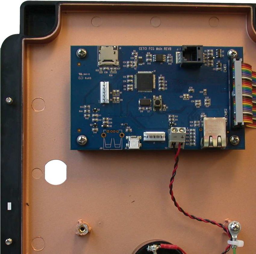
FCS - Installation Manual                                                                                                               Rev. C | 2019.06

                                                 TABLE OF CONTENTS
1 POLICIES ................................................................................................................................. 5
       1.1 Important Note ............................................................................................................................5
       1.2 Warranty Policy ............................................................................................................................5
       1.3 Service Policy ...............................................................................................................................6
       1.4 Copyrights and Registered Trademarks ........................................................................................6
       1.5 Disclaimer ....................................................................................................................................6
       1.6 Revisions ......................................................................................................................................7
2 INTRODUCTION .................................................................................................................... 7
       2.1 General Description......................................................................................................................7
       2.2 Key Features.................................................................................................................................8
3 INSTRUMENT SPECIFICATIONS .......................................................................................... 9
       3.1 Technical Specifications................................................................................................................9
       3.2 Enclosure Dimensions ................................................................................................................11
4 LIST OF COMPATIBLE DEVICES ......................................................................................... 12
5 INSTRUMENT FEATURES.................................................................................................... 13
       5.1 Front Exterior Enclosure .............................................................................................................13
       5.2 Interior System Layout (Bottom) Shown with Options -AI and AO Installed ...............................14
       5.3 Interior System Layout (Door) ....................................................................................................15
       5.4 Optional Internal Analog Inputs and Analog Outputs (Options -AI and -AO) ..............................16
             5.4.1 Maximum Number of Analog Inputs (FCS 128 Channel Model) .....................................17
             5.4.2 Maximum Number of Analog Inputs (FCS-8 8 Channel Model) ......................................17
             5.4.3 Maximum Number of Analog Outputs (FCS 128 Channel Model) ...................................17
             5.4.4 Maximum Number of Analog Outputs (FCS-8 8 Channel Model) ...................................18
6 INSTALLATION ..................................................................................................................... 18
       6.1 General Safety Warnings ............................................................................................................18
       6.2 Protection Against Electrical Risks..............................................................................................18
       6.3 Protection Against Mechanical Risks ..........................................................................................19
       6.4 Location of System Installation ..................................................................................................19
             6.4.1 Wet Environment Considerations ...................................................................................19
             6.4.2 EMI and RF Interference Considerations .........................................................................19
       6.5 Standard Enclosure Mounting Components ...............................................................................20
             6.5.1 Enclosure Interior Base ..................................................................................................20
             6.5.2 Enclosure Top and Bottom .............................................................................................20
       6.6 Wiring Power Supply Connections..............................................................................................21
       6.7 Wire Gauge vs Run Length .........................................................................................................21
       6.8 Wiring a Remote Power Supply (RPS-24VDC) .............................................................................22

2                                                                            © 2019 All rights reserved. Data subject to change without notice.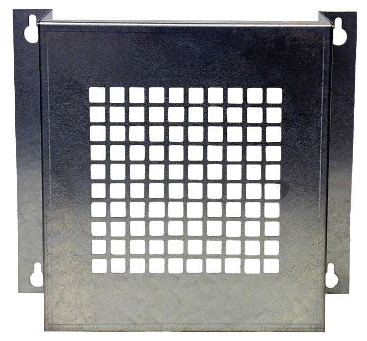
Rev. C | 2019.06                                                                                                              FCS - Installation Manual

       6.9 Wiring Internal Analog Outputs (Option -AO) .............................................................................24
       6.10 Wiring Internal Analog Inputs (Option -AI)...............................................................................25
       6.11 Wiring LNK-AO Peripheral Device (additional Analog Outputs) ................................................26
       6.12 Wiring LNK-AI Peripheral Device (additional Analog Inputs) ....................................................27
       6.13 Wiring Digital Inputs (LPT-P and LPT-M Transmitters) ..............................................................28
       6.14 Wiring LNK-XT Network Extender Peripheral Device Connections ............................................29
       6.15 Wiring to Building Automation System (BAS) ..........................................................................30
       6.16 Wiring Remote Strobe / Horn Using Output Terminal ...............................................................31
       6.17 Wiring Internal Relay Connections ...........................................................................................31
       6.18 Wiring Remote Relay Connections (RLY-4 and RLY-8) ...............................................................32
       6.19 Wiring QCC-RDM Remote Display Connections .........................................................................33
       6.20 Wired Example of an FCS Gas Detection System .......................................................................35
7 SYSTEM OPERATION .......................................................................................................... 36
       7.1 Navigating the Menu Structure ..................................................................................................36
       7.2 Accessing the Menu with Passcodes ...........................................................................................36
       7.3 Power Up and Warm-up .............................................................................................................38
       7.4 Home Screen Display..................................................................................................................39
       7.5 Channel Status Bar Operation ....................................................................................................39
       7.6 Relay, Strobe, Horn and Audible Status Bar Operation................................................................41
       7.7 Peripherals and Remote Devices Status Bar Operation ...............................................................44
       7.8 Integral Audible Alarm Operation, Terminal Connected Strobe / Horn and Remote
           Strobe / Horn Operation .............................................................................................................44
       7.9 Test Menu Functions ..................................................................................................................45
             7.9.1 Test Audible (Buzzer) .....................................................................................................46
             7.9.2 Test Strobe .....................................................................................................................47
             7.9.3 Test Relays .....................................................................................................................47
             7.9.4 Test Analog Outputs .......................................................................................................48
       7.10 Recalibrating the Display to Improve Response........................................................................48
8 BASIC SETTINGS AND CONFIGURATIONS ...................................................................... 49
       8.1 Set Clock ....................................................................................................................................49
       8.2 Set Data Logger Sample Rate .....................................................................................................49
       8.3 Modbus® Setup / BACnet® Setup ...............................................................................................50
             8.3.1 Set Modbus® ID, Remote Baud Rate & Local Baud Rate..................................................51
             8.3.2 Set WAN BACnet® Base Address, MAC Address & Baud Rate ...........................................52
       8.4 Configure QCC-RDM Remote Display(s) ......................................................................................52

© 2019 All rights reserved. Data subject to change without notice.                                                                                        3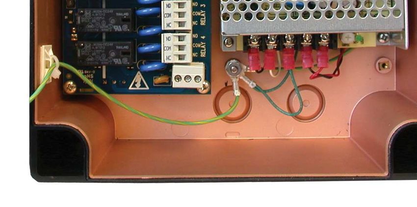
FCS - Installation Manual                                                                                                            Rev. C | 2019.06

9 CHANNEL SETTINGS AND CONFIGURATIONS ............................................................... 54
       9.1 Enable / Disable Channels, Assign ID, Channel Number & Communication Type.........................54
       9.2 Set Channel Name, UOM and Gas Range Values .........................................................................55
       9.3 Set Channel Alarm Setpoints......................................................................................................57
10 RELAY, STROBE, HORN AND AUDIBLE SETTINGS AND CONFIGURATIONS ............ 58
       10.1 Enable / Disable Relays, Assign Modbus ID & Change Mode of Operation ................................58
       10.2 Using Relay Timers to Set ON / OFF Delays................................................................................60
11 ANALOG INPUT AND ANALOG OUTPUT SETTINGS ................................................... 61
           Maximum Number of Singular Analog Input or Output Devices Accepted ................................61
           Maximum Number of Combined Analog Input or Output Devices Accepted .............................61
       11.1 Enable / Disable Internal & Remote Analog Inputs, Assign Modbus ID, CH # & Type .................62
       11.2 Enable / Disable Internal & Remote Analog Outputs, Assign Modbus ID, CH # & Type ..............64
12 OPTIONS AND ACCESSORIES ......................................................................................... 66
       12.1 Top Mounted Strobe (Option -L) ...............................................................................................66
       12.2 Manual Shutoff Switch (Option -SW) .......................................................................................66
       12.3 Enclosure Door Lock and Keys (Option -DL) ..............................................................................67
       12.4 Metal Protective Guard ............................................................................................................67
       12.5 Calibration Kit ..........................................................................................................................68
13 MAINTENANCE ................................................................................................................. 68
14 TROUBLESHOOTING ........................................................................................................ 69

4                                                                          © 2019 All rights reserved. Data subject to change without notice.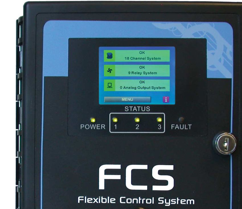
Rev. C | 2019.06                                                                          FCS - Installation Manual

1 POLICIES
1.1 Important Note
Read and understand this manual prior to using this instrument. Carefully read the warranty policy,
service policy, notices, disclaimers and revisions on the following pages.

This product must be installed by a qualified electrician or factory trained technician and according to
instructions indicated in this manual. This instrument should be inspected and maintained on a regular
basis by a qualified and trained technician.

This instrument has not been designed to be intrinsically safe. For your safety, do not use it in classified
hazardous areas (explosion-rated environments).

INSTRUMENT SERIAL NUMBER:
__________________________________________________________

PURCHASE DATE:
__________________________________________________________

PURCHASED FROM:

__________________________________________________________

1.2 Warranty Policy
Critical Environment Technologies Canada Inc. (CETCI), also referred to as the manufacturer, warrants this
instrument, (excluding sensors, battery packs, batteries, pumps and filters) to be free from defects in
materials and workmanship for a period of two years from the date of purchase from our facility.
If the product should become defective within this warranty period, we will repair or replace it at our
discretion.

The warranty status may be affected if the instrument has not been used and maintained per the
instructions in this manual or has been abused, damaged, or modified in any way. This instrument is only
to be used for purposes stated herein. The manufacturer is not liable for auxiliary interfaced equipment or
consequential damage.

Due to ongoing research, development, and product testing, the manufacturer reserves the right to
change specifications without notice. The information contained herein is based on data considered
accurate. However, no warranty is expressed or implied regarding the accuracy of this data.

All goods must be shipped to the manufacturer by prepaid freight. All returned goods must be pre-
authorized by obtaining a Returned Merchandise Authorization (RMA) number. Contact the manufacturer
for a number and procedures required for product transport.

© 2019 All rights reserved. Data subject to change without notice.                                               5
FCS - Installation Manual                                                                               Rev. C | 2019.06

1.3 Service Policy
CETCI maintains an instrument service facility at the factory. Some CETCI distributors / agents may also
have repair facilities; however, CETCI assumes no liability for service performed by anyone other than CETCI
personnel.

Repairs are warranted for 90 days after date of shipment (sensors have individual warranties).

Should your instrument require non-warranty repair, you may contact the distributor from whom it was
purchased or you may contact CETCI directly.

Prior to shipping equipment to CETCI, contact our office for a Returned Merchandise Authorization (RMA)
number. All returned goods must be accompanied with an RMA number.

If CETCI is to do the repair work, you may send the instrument, prepaid, to:
    Attention: Service Department
    Critical Environment Technologies Canada Inc.
    Unit 145, 7391 Vantage Way
    Delta, BC, V4G 1M3

Always include your RMA number, address, telephone number, contact name, shipping / billing
information, and a description of the defect as you perceive it. You will be contacted with a cost estimate
for expected repairs, prior to the performance of any service work.

For liability reasons, CETCI has a policy of performing all needed repairs to restore the instrument to full
operating condition.

Pack the equipment well (in its original packing if possible), as we cannot be held responsible for any
damage incurred during shipping to our facility.

1.4 Copyrights and Registered Trademarks
This manual is subject to copyright protection; all rights are reserved. Under international and domestic
copyright laws, this manual may not be copied or translated, in whole or in part, in any manner or format,
without the written permission of CETCI.

All software which CETCI utilizes and / or distributes holds a proprietary interest and is also subject to
copyright protection and all rights are reserved. No party may use or copy such software in any manner
or format, except to the extent that CETCI grants them a license to do so. IF SOFTWARE IS BEING LOADED
ONTO MORE THAN ONE COMPUTER, EXTRA SOFTWARE LICENSES MUST BE PURCHASED.

Modbus® is a registered trademark of Gould Inc. Corporation. BACnet® is a registered trademark of
American Society of Heating, Refrigerating and Air-Conditioning Engineers (ASHRAE).

1.5 Disclaimer
Under no circumstances will CETCI be liable for any claims, losses or damages resulting from or arising
out of the repair or modification of this equipment by a party other than CETCI service technicians, or by

6                                                      © 2019 All rights reserved. Data subject to change without notice.
Rev. C | 2019.06                                                                            FCS - Installation Manual

operation or use of the equipment other than in accordance with the printed instructions contained within
this manual or if the equipment has been improperly maintained or subjected to neglect or accident. Any
of the foregoing will void the warranty.

Under most local electrical codes, low voltage wires cannot be run within the same conduit as line voltage
wires. It is CETCI policy that all wiring of our products meet this requirement.

It is CETCI policy that all wiring be within properly grounded (earth or safety) conduit.

1.6 Revisions
This manual was written and published by CETCI. The manufacturer makes no warranty or representation,
expressed or implied including any warranty of merchantability or fitness for purpose, with respect to this
manual.

All information contained in this manual is believed to be true and accurate at the time of printing.
However, as part of its continuing efforts to improve its products and their documentation, the
manufacturer reserves the right to make changes at any time without notice. Revised copies of this
manual can be obtained by contacting CETCI or visiting
www.critical-environment.com.

Should you detect any error or omission in this manual, please contact CETCI at the following address:

Critical Environment Technologies Canada Inc.
Unit 145, 7391 Vantage Way, Delta, BC, V4G 1M3, Canada
Toll Free:            +1.877.940.8741
Telephone:            +1.604.940.8741
Fax:                  +1.604.940.8745
Email:                marketing@cetci.com
Website:              www.critical-environment.com

In no event will CETCI, its officers or employees be liable for any direct, special, incidental or consequential
damages resulting from any defect in any manual, even if advised of the possibility of such damages.

2 INTRODUCTION
2.1 General Description
NOTE: The FCS Installation Manual outlines the basic features and functionality of the FCS and includes
information about installing and wiring the system. If you require more in depth information about how
the FCS can be configured (channels, relays, strobe/audible and analog input and output settings), using
passcodes, logic and priority settings and the Modbus® holding registers, please download the FCS Operation
Manual from our website.

If you have purchased the FCS-8, the majoirty of the functionality outlined in this manual
applies, with the exception of number of channels and number of Peripheral Devices that

© 2019 All rights reserved. Data subject to change without notice.                                                 7

FCS - Installation Manual                                                                               Rev. C | 2019.06

the FCS-8 can accommodate. For a list of the differences, refer to Section 4 List of Compatible
Devices.

Thank you for purchasing our FSC Flexible Control System. The FCS Flexible Control System is a sophis-
ticated, high performance controller that offers up to 128 (or limited to 8) gas channel configurations for
monitoring toxic, combustible or refrigerant gases with versatile control functionality for non-hazardous,
non-explosion rated, commercial and light industrial applications.

The FCS is designed to accept inputs from digital and/or analog transmitters and/or peripheral devices (in
various combinations), using Modbus® RTU RS-485 or 4-20 mA analog input.

The FCS is available in 4 models:
    • FCS-M - up to 128 channels with Modbus® RTU RS-485 WAN output to BAS
    • FCS-8-M - maximum 8 channels with Modbus® RTU RS-485 WAN output to BAS
    • FCS-B - up to 128 channels with BACnet® MS/TP RS-485 WAN output to BAS
    • FCS-8-B - maximum 8 channels with BACnet® MS/TP RS-485 WAN output to BAS

2.2 Key Features
    • A 1/4 VGA full colour, resistive touch LCD display with an LED panel for alarm status fault conditions
    • Extensive menu system with password protection
    • Has a USB port for in the field firmware upgrades and data logging downloads
    • Configured with either a Modbus® RTU RS-485 or a BACnet® MS/TP RS-485 digital output signal for
      WAN communications (for communicating with a BAS)
    • Supports Modbus® driven VFDs
    • Flexible configuration of analog outputs
    • Enhanced logic control, zoning and priority structure capabilities
    • With the optional Analog Output board(s) (Option -AO or -2AO) installed, the FCS can be configured
      to have up to 8 internal 4-20 mA outputs for VFD control or usable by any other device requiring a
      signal representing the levels of gases detected
    • With the optional Analog Input board(s) (Option -AI or -2AI) installed, the FCS can be configured to
      have up to 8 internal analog inputs
    • A door mounted, loud audible alarm that is ideal for noisy environments.
    • Four 5-amp SPDT dry contact relays with field configurable time delays and trigger levels
    • Two horn/strobe output drives
    • Additional application specific options include: enclosure door lock and key, a top mounted strobe,
      internal heater and a water tight, door mounted audible alarm.

8                                                      © 2019 All rights reserved. Data subject to change without notice.
Rev. C | 2019.06                                                                                FCS - Installation Manual

   • The FCS can be connected to a remote strobe/horn combo, an FCS-RDM Remote Display Module,
     and the following peripheral devices: LNK-AO Analog Output, LNK-AI Analog Input, LNK-XT Network
     Extender, RLY-4 Remote Relay, RLY-8 Remote Relay and RPS-24VDC Remote Power Supply.
   • Six conduit entry ports
   • Thermal resetting fuses
   • RoHS compliant circuit boards

If after reading through the manual you have any questions, please do not hesitate to contact our service
department for technical support.

3 INSTRUMENT SPECIFICATIONS
3.1 Technical Specifications
 GAS TYPE
 No internal gas sensors

 MECHANICAL
                                       ABS / Polycarbonate, rated UL94-HB. Copper coated interior to reduce RF
 Enclosure
                                       interference. IP54 rating with door mounted, water tight buzzer installed.
 Weight                                1.8 kg / 4 lbs
 Size                                  254 mm x 226 mm x 113 mm / 10 in x 8.9 in x 4.44 in

 USER INTERFACE
                                        8.1 cm / 3.2 in graphic, 1/4 VGA full colour resistive touch LCD display
 Display
                                        and LED indicators for “POWER”, “STATUS 1, 2 and 3” , “FAULT”

 INPUT/OUTPUT
                                        - Modbus® RTU RS-485
 Inputs                                 - Four or eight internal 4-20 mA analog inputs (Option -AI or -2AI)
                                        - Peripheral devices on Modbus® RTU RS-485 network
                                        - Modbus® RTU RS-485 (models: FCS-M, FCS-8-M)
                                        - BACnet® MS/TP to BAS (models: FCS-B, FCS-8-B)
 Outputs                                - Four or eight internal 4-20 mA analog outputs (Option -AO or -2AO)
                                        - Remote and Peripheral devices on a Modbus® RTU RS-485 network
                                        - Two drive outputs for strobe/horn (0.5 Amp @ 24 V max)
 Relays (internal)                      Four internal SPDT dry contact relays, rated 5A @ 240 VAC

© 2019 All rights reserved. Data subject to change without notice.                                                     9
FCS - Installation Manual                                                                         Rev. C | 2019.06

                            - Standard door mounted buzzer, rated 90 dB @ 30 cm (1 ft)
 Audible Alarm              - Optional door mounted water tight buzzer (Option -WA), rated
                              85 dB @ 60.96 cm / 2 ft
 Top Mounted Strobe         24 V, 114 mm H x 76 mm dia / 4.5 in H x 3 in diameter (Option -L)

 ELECTRICAL
 Power Requirement          90 - 240 VAC, 50 - 60 Hz, 75 W Line Voltage
 Current Draw
      Line Voltage (110 VAC) Approximately 1.0 Amp
      Line Voltage (220 VAC) Approximately 0.5 Amp
                            Total power available to Remote and Peripheral Devices and Options
 Power Distribution
                            65 W @ 24 VDC
                            - VAC (line voltage) three-conductor (Line, Neutral, Ground)
                             shielded minimum 18 AWG stranded within conduit
                            - LAN Modbus® RTU RS-485 4-conductor, 16 AWG, stranded shielded
 Wiring
                            - WAN (output to BAS): 4-conductor, 16 AWG, stranded shielded
                                   Modbus® RTU (version 1.1b3) RS-485 or
                                   BACnet® MS/TP (version 1 rev 14) RS-485
                          LAN Baud rate: 19,200 (default, configurable)
                          WAN Baud rate: 19,200 (default, configurable)
 LAN / WAN Communication: WAN Modbus ID: 100 (factory default)
 Modbus® RTU over RS-485 Data bits: 8
                          Stop bits: 1
                          Parity: none
                            Baud rate: 76,800 (default, configurable)
                            Base Address: 270 (factory default)
                            MAC Address: 100 (factory default)
 WAN Communication:
                            Instance ID: 270100 (the Base Address x 1000 + the MAC Address)
 BACnet® MS/TP
                            Data Bits: 8
                            Stop Bits: 1
                            Parity: none
 Fuses                      Automatic resetting thermal

 ENVIRONMENTAL
 Operating Temperature      -20°C to 40°C (-4°F to 104°F)
 Operating Humidity         15 - 90% RH non-condensing

10                                               © 2019 All rights reserved. Data subject to change without notice.
Rev. C | 2019.06 FCS - Installation Manual
CERTIFICATION
Models: FCS-M-xx / FCX-8-M-xx or FCS-B-xx / FCS-8-B-xx
S/N: FCSM1603B00001 (example)
Rating: 90-240 VAC, 50-60 Hz, 75 W
CERTIFIED FOR ELECTRIC SHOCK & ELECTRICAL FIRE HAZARD ONLY. LA CERTIFICATION ACNOR COUVRE
UNIQUEMENT LES RISQUES DE CHOC ELECTRIQUE ET D’INCENDIE D’ORIGINE ELECTRIQUE.
Conforms to: CSA-C22.2 No. 205-12, UL508 (Edition 17):2007
Conforms to: EMC Directive 2004/108/EC, EN 50270:2006, Type 1, EN61010
Conforms to: FCC. This device complies with part 15 of the FCC Rules, Operation is subject to the
following two conditions: (1) This device may not cause harmful interference, and (2) this device must
accept any interference received, including interference that may cause undesired operation.
NOTES:
• System default is configured such that all relays are “FAIL SAFE” (relay coils are always energized in
non-alarm state).
• Relays are “common” to channels (activated by multiple alarm conditions).
3.2 Enclosure Dimensions
226 mm (8.9”)
254 mm
(10.0”)
113 mm (4.44”)
© 2019 All rights reserved. Data subject to change without notice. 11FCS - Installation Manual Rev. C | 2019.06
4 LIST OF COMPATIBLE DEVICES
NOTE: The FCS does not have any internal gas sensors. It is strictly a controller that can accept digital and
analog inputs (ie. transmitters and other remote and/or peripheral devices).
Analog and/or Output
Signal Gases Sensor Type
Digital Transmitters
R134A, R404A, R407A,
R407C, R407F, R410A,
R427A, R448A, R449A,
4-20 mA or
ART Infrared Refrigerant R507, HF01233ZD, R422A, Infrared
Modbus®
R422D, R45sA, R513A,
HF01234YF, HF01234ZE,
R22, R32
AST-IS18-M CO2 Transmitter Modbus® CO2 Infrared
AST-IS12 CO2 Transmitter Modbus® CO2 Infrared
all other AST-IS CO2 Transmitters 4-20 mA CO2 Infrared
4-20 mA or NH3, CO, CO2, H2, H2S, NO2, Electrochemical,
CXT Explosion Proof
Modbus® O2, PH3, SO2, CH4, C3H8, C5H12 Infrared, Catalytic
LPT Low Power 4-20 mA NH3, CO, NO2, Cl2, O2, O3 Electrochemical
NH3, CO, NO2, CLO2, Cl2,
C3H4, C2H4O, CH2, H2, H2S,
Electrochemical, Solid
LPT-A Analog 4-20 mA HCl, HCN, NO, O2, O3, PH3,
State, Catalytic
SIH4, SO2, CH4, C3H8, TVOCs,
Refrigerants
LPT-M Modbus Modbus® same as LPT-A same as LPT-A
Electrochemical and
LPT-P Digital Car Park Modbus® CO, NO2, H2, CH4, C3H8
Catalytic
CETCI Peripheral and Output # of Devices
Remote Devices Signal Limit *
FCS FCS-8
LNK-AO Analog Output Modbus® Four 4-20 mA outputs 15 2
LNK-AI Analog Input Modbus® Four 4-20 mA inputs 15 2
LNK-XT Network Extender Modbus® BUS Network Extender 6 **
QCC-RDM Remote Display Modbus® Displays gas readings 20 4
RLY-4 Remote Relay Modbus® Four, 5 Amp, 120/240 VAC 14 2
12 © 2019 All rights reserved. Data subject to change without notice.Rev. C | 2019.06 FCS - Installation Manual
RLY-8 Remote Relay Modbus® Eight, 5 Amp, 120/240 VAC 7 1
RPS-24VDC Remote Power
Modbus® 24 VDC, 2 Amp 6 **
Supply
RAA-90 Remote Audible Alarm 1 1
RAA-90-W Remote Audible 24 VDC, 2-wire (one or (one or
Alarm (water tight) the other) the other)
RSH-24VDC Remote Strobe/Horn Use relay or strobe drive 2 2
* This is the total number possible on an individual/absolute basis without consideration of other internal options installed or
devices on the network. Limits will change depending on what internal options are installed and the number of and type of devices
connected to the network. ** It is unlikely that an LNK-XT Network Extender or an Remote Power Supply will be needed with an
FCS-8 system.
5 INSTRUMENT FEATURES
5.1 Front Exterior Enclosure
Œ
‘
• •
•
Ž
‘
’
NUMBER FEATURE FUNCTION
1/4 VGA full colour resistive touch LCD display, indicates
ΠDisplay
controller operation
• Power LED Indicates unit power status
Ž Status 1, 2, 3 LEDs Indicates channel status - OK, Low / Mid / High alarm
© 2019 All rights reserved. Data subject to change without notice. 13FCS - Installation Manual Rev. C | 2019.06
• Fault LED Indicates unit fault condition
• Key Lock (Option -DL) Allows enclosure to be locked
‘ Door Screws Secures the door of the enclosure
Audible buzzer that sounds when a channel has gone
’ Door Mounted Alarm
into alarm
5.2 Interior System Layout (Bottom)
Shown with Options
pt -AI and -AO Installed
Œ
•
Ž
“
•
”
•
•
‘
’ ”
⓫
“
12
NUMBER FEATURE FUNCTION
Two connections for a remote 24 VDC horn and/or
ΠHorn/Strobe Output Terminal strobe combination (ie. RSH-24VDC)
0.5 Amps max.
For connection to BAS (Modbus® or BACnet®)
• WAN Terminal
(no 24 VDC connection)
Ž WAN End of Line Jumper 120 ohm line termination
• Option -AI or Option -AO An optional board with 4 analog inputs or Outputs
14 © 2019 All rights reserved. Data subject to change without notice.Rev. C | 2019.06 FCS - Installation Manual
• Analog Input Terminal Connection for up to four 4-20 mA transmitters
An optional board with 4 analog outputs
‘ Option -AO NOTE: this could be Option -AI instead. Refer to
Section 5.4 for more information
’ Analog Output Terminal Connection for up to four 4-20 mA outputs
“ Earth Ground Earth / safety ground connection
Connections for Modbus® transmitters and/or
” LAN Terminals
peripheral devices
• LAN End of Line Jumper 120 ohm line termination
⓫ Relay Terminals Four SPDT relays, rated 5 amps @ 240 V
12 Line Voltage Terminal 120 or 240 VAC input
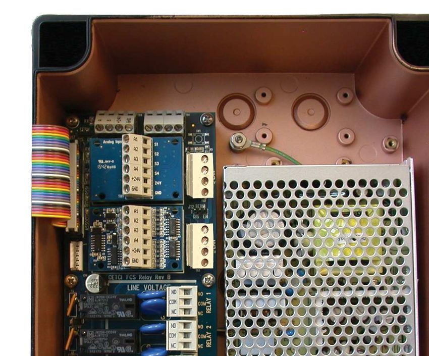
5.3 Interior System Layout (Door)
•
Œ
Ž
•
•
NUMBER FEATURE FUNCTION
ΠMicro USB Connector For system updates and downloading data logging
• Programming Port For factory system programming
© 2019 All rights reserved. Data subject to change without notice. 15FCS - Installation Manual Rev. C | 2019.06
Ž Buzzer Terminal Connection for door mounted buzzer
• Earth Ground Earth / safety ground connection
• Buzzer Internal audible alarm
5.4 Optional Internal Analog Inputs and Analog Outputs
(Options -AI and -AO))
The FCS does not have any internal analog inputs or analog outputs without the optional -AI and -AO
boards installed. These boards are independent of each other and plug into the main FCS board.
FCS main board without the optional Analog
Input (-AI) or Analog Output (-AO) boards
installed.
The Analog Input board (Option –AI) has four analog inputs.
The Analog Output board (Option –AO) has four analog outputs.
16 © 2019 All rights reserved. Data subject to change without notice.Rev. C | 2019.06 FCS - Installation Manual The optional boards can be installed in the same FCS in combinations of (each line is exclusive of the other): • One –AI board, therefore 4 Analog Inputs (Option -AI) • Two –AI boards, therefore 8 Analog Inputs (Option -2AI) • One –AO board, therefore 4 Analog Outputs (Option -AO) • Two AO boards, therefore 8 Analog Outputs (Option -2AO) • One –AI and one –AO board, therefore 4 Analog Inputs and 4 Analog Outputs (Option -AIAO) 5.4.1 Maximum Number of Analog Inputs - FCS 128 Channel Model The maximum number of internal analog inputs that can be accommodated by the FCS is eight (two factory installed -AI boards). If more analog inputs are required, they can be added by using one or more LNK-AI Analog Input Peripheral Devices. Each LNK-AI has four analog inputs, Modbus® communication and an LED power indicator. The LNK-AI connects to the LAN Terminal on the FCS and to other devices in a daisy-chain fashion. Refer to Section 6.12 Wiring LNK-AI Peripheral Device (additional Analog Inputs) for information on wiring an LNK-AI to the FCS. The maximum number of analog inputs (internal + remote) the FCS can support is 60. This can be made up of 2 –AI boards (8 internal analog inputs) plus 13 LNK-AI Peripheral Devices (4x13 analog inputs = 52) 8 internal + 52 remote = 60 total. Or no internal analog inputs and 15 LNK-AI Peripheral Devices (4x15 = 60). NOTE: Each configured analog input will take up one of the 128 available sensor channels. For example, if the system is configured with 48 analog inputs (and no digital transmitters), 80 gas channels remain for use. 5.4.2 Maximum Number of Analog Inputs - FCS-8 8 Channel Model The maximum number of internal analog inputs that can be accommodated by the FCS-8 is the same as the FCS, which is eight (two factory installed -AI boards). The maximum number of analog inputs (internal + remote) the FCS-8 can support is 8. This can be made up of 1 –AI board (4 internal analog inputs) plus 1 LNK-AI Peripheral Device (4 remote analog inputs) 4 internal + 4 remote = 8 total. Or no internal analog inputs and 2 LNK-AI Peripheral Devices (4x2 = 8). NOTE: Each configured analog input will take up one of the 8 available sensor channels. For example, if the system is configured with 4 analog inputs (and no digital transmitters), 4 gas channels remain for use. 5.4.3 Maximum Number of Analog Outputs - FCS 128 Channel Model The maximum number of internal analog outputs that can be accommodated by the FCS is eight (two factory installed -AO boards). © 2019 All rights reserved. Data subject to change without notice. 17
FCS - Installation Manual                                                                              Rev. C | 2019.06

If more analog outputs are required, they can be added by using one or more LNK-AO Analog Output
Peripheral Devices. Each LNK-AO has 4 analog outputs, Modbus® communication and an LED power
indicator. The LNK-AO connects to the LAN Terminal on the FCS and to other devices in a daisy-chain
fashion. Refer to Section 6.11 Wiring LNK-AO Peripheral Device (additional Analog Outputs) for information
on wiring an LNK-AO to the FCS.

The maximum number of analog outputs (internal +remote) the FCS can support is 60. This can
be made up of 2 –AO boards (8 internal analog outputs) plus 13 LNK-AO Peripheral Devices (4x13 analog
outputs = 52). 8 internal + 52 remote = 60 total. Or no internal analog outputs and 15 LNK-AO Peripheral
Devices (4x15 = 60).

5.4.4 Maximum Number of Analog Outputs - FCS-8 8 Channel Model
The maximum number of internal analog outputs that can be accommodated by the FCS-8 is the same
as the FCS, which is eight (two factory installed -AO boards).

The maximum number of analog outputs (internal + remote) the FCS-8 can support is 8. This can
be made up of 1 –AO board (4 internal analog outputs) plus 1 LNK-AO Peripheral Device (4 remote analog
outputs) 4 internal + 4 remote = 8 total. Or no internal analog outputs and 2 LNK-AO Peripheral Devices
(4x2 = 8).

NOTE: The maximum number of analog outputs will be different if configured as Modbus® VFDs. Refer to
Section 12 Analog Input and Analog Output Settings for more information.

6 INSTALLATION
6.1 General Safety Warnings
The FCS is intended for indoor use, permanently mounted in a locked electrical room. It should be
protected from extreme weather conditions.

The FCS requires no assembly and virtually no maintenance other than configuration of the channels and
ensuring that excess water or dust is not somehow entering the enclosure and physically damaging the
circuit board or internal components.

6.2 Protection Against Electrical Risks
Warning High Voltage. Indicates hazardous voltage may be present in the area inside the FCS enclosure
marked with this symbol.

Disconnect all power before servicing. There may be multiple power sources. Power supply must have
a building installed circuit breaker/switch that is suitably located and easy to access when servicing is
required and should be labelled as FCS supply (disconnecting power to the FCS). Appropriate markings
should be visible at the circuit breaker/switch that is supplying power to the FCS. The relays should be
connected to alternate circuit breakers and these should be appropriately marked.
18                                                    © 2019 All rights reserved. Data subject to change without notice.
Rev. C | 2019.06                                                                         FCS - Installation Manual

This device may interfere with pacemakers. Modern pacemakers have built-in features to protect them
from most types of interference produced by other electrical devices you might encounter in your daily
routine. If you a have a pacemaker, follow your healthcare provider’s instructions about being around this
type of equipment.

6.3 Protection Against Mechanical Risks
Be aware that the FCS enclosure has a hinged door that could potentially pinch fingers and the sharp
edges and/or jumper pins on the board could potentially prick or cut fingers if not handled carefully.

6.4 Location of System Installation
The FCS should be installed on a flat vertical surface using the four 0.175” (4.4 mm) diameter mounting
holes in the corners of the enclosure that are provided. This will help maintain the water tight status of the
enclosure.

There are ten available conduit entry points - three are located along the top of the enclosure, three are
located along the bottom and four are located on the back. These points may be drilled out as needed.
Refer to Section 6.5 Standard Enclosure Mounting Components for more information.

NOTE: When mounting the enclosure, allow enough room to allow the end user to open the door fully to
access the internal adjustments (23 cm / 9 in of space on the left side of the enclosure).

When finished installing or servicing it is recommend you perform a test to ensure the unit and all relays
are working properly.

6.4.1 Wet Environment Considerations
If the FCS is to be installed in a potential hose-down application or any application whereby liquid could
be directed towards the buzzer, the FCS should be ordered with an optional watertight door mounted
buzzer (factory installed).

If used in a wet environment application, the conduit hubs entering the FCS enclosure must
be a liquid tight type.

Any water or physical damage to the FCS that occurs from the installer drilling their own installation holes
will not be covered under CETCI’s warranty.

6.4.2 EMI and RF Interference Considerations
All electronic devices are susceptible to EMI (Electromagnetic Interference) and RFI (Radio Frequency
Interference). Our controllers and detectors have been designed to reduce the effects of these
interferences and we meet CSA, FCC and CE requirements for these type of devices. However there are still
circumstances and levels of interference that may cause our equipment to respond to these interferences
and cause them to react as if there has been gas detected.

There are some installation procedures that will reduce the likelihood of getting faulty readings:
     1. Locate the detectors and controllers out of the way from normal foot traffic and high energy
        equipment.
© 2019 All rights reserved. Data subject to change without notice.                                             19
FCS - Installation Manual Rev. C | 2019.06
2. Confirm the devices are properly grounded using conduit and shielded cabling.
3. Inform operators and technical staff working in the surrounding area to be aware of these possible
conditions and that two way radios, Bluetooth enabled devices, cell phones and other electrical
equipment may interfere with the response of the gas detectors.
6.5 Standard Enclosure Mounting Components
6.5.1 Enclosure Interior Base
Œ Œ
• •
• •
Œ Œ
NUMBER FUNCTION
ΠMolded-in mounting holes
• Conduit entry points
6.5.2 Enclosure Top and Bottom
The top and bottom of the enclosure are identical, each offering molded-in mounting holes and three
conduit entry points.
20 © 2019 All rights reserved. Data subject to change without notice.Rev. C | 2019.06 FCS - Installation Manual
•
• •
Œ Œ
NUMBER FUNCTION
ΠMolded-in mounting bracket
• Conduit entry points
6.6 Wiring Power Supply Connections
The FCS requires a 90 - 240 VAC power supply (line voltage power). This source should be on an
independent breaker that is properly marked.
Very carefully, drill out one or more of the PVC conduit entry hole plugs located on the top, bottom or
back of the system enclosure base. Refer to Section 6.5 Standard Enclosure Mounting Components for the
locations of the conduit entry holes.
Wire the field wiring to the Line Voltage Terminal (J15), refer to Section 5.2 Interior System Layout
(Bottom). These are the power connections and should be supplied with a minimum 3-conductor, 18 AWG
stranded wiring.
All wiring should be run in EMT (or better) conduit properly grounded (earth or safety). Building code
requires low voltage wiring not to be within the same conduit as line voltage wiring. All communications
(network) wiring must be in shielded cabling. Wire shielding must be connected together at each
device and taped off so it cannot cause a short on the circuit board when the door is closed.
The wire shielding should be connected to earth ground close to the primary supply connection only, and
must have a contiguous connection throughout the network. It should be left taped and floating at the
last device in the network.
6.7 Wire Gauge vs Run Length
It is important to use the appropriate gauge of wire for the required length of the run to ensure sufficient
available voltage, noise reduction, dissipation of heat, and overall optimum performance along the entire
wire run. Large wire sizes will have less voltage drop than smaller wires sizes of the same length. Similarly,
shorter wire lengths will have less voltage drop than longer wires for the same wire size. The longer the
wire run, the more attention there should be made to preventing voltage drop.
© 2019 All rights reserved. Data subject to change without notice. 21FCS - Installation Manual Rev. C | 2019.06
CETCI highly recommends 4-conductor, 16 AWG, shielded, stranded wire cable types such as
AlphaWire 79220, AlphaWire 5534, Belden 9954 or equivalent. Do not use solid core wire.
Minimum Cable Length vs Size (AWG) for Modbus® and Power Supply
Cable Length # of
4 6 8 10 12 14 16
Meters Feet Sensors
0.3 to 1552 1 to 500 AWG # 18 18 18 18 18 18 18
153 to 305 501 to 1, 000 AWG # 18 18 18 18 18 18 18
306 to 457 1,001 to 1,500 AWG # 18 18 18 16 16 16 16
458 to 914 1,501 to 3,000 AWG # 18 16 16 16 16 16 16
NOTE: WARRANTY MAY BE VOID IF DAMAGE OCCURS TO CIRCUIT BOARD COMPONENTS FROM THE
USE OF SOLID CORE WIRE ATTACHED DIRECTLY TO THE WIRING TERMINALS. When using solid core
wiring for distribution (in the conduit), use stranded wire pigtails 18 awg within the enclosure to connect
to the circuit board. The rigidity of solid-core wire can pull a soldered terminal strip completely off a circuit
board and this will not be covered under warranty.
Communication wiring uses a daisy chain configuration. From one digital device to the next digital device,
A goes to A; B goes to B; GND goes to GND; 24V goes to 24V. No tee taps. No star configurations. An end of
line jumper must be installed at both ends of the network.
6.8 Wiring a Remote Power Supply (RPS-24VDC)
The RPS-24VDC is a remote power supply designed for use with system installations that require a large
number of remote digital transmitters or very long wiring runs. As a general rule, the FCS Controller will
supply up to 65 watts of power. The total number of transmitters that can be powered by the FCS without
a remote power supply will depend on the number and type of devices:
Each Single Device Power Consumption
LPT-P or LPT-M Transmitter with internal sensor(s) 1 watt
LPT-P or LPT-M Transmitter with an ESH-A remote sensor 3 watts
RLY-4 Remote Relay (4 relays) 3 watts
RLY-8 Remote Relay (8 relays) 6 watts
LNK-AI Analog Input Peripheral Device
1 watt
(not including the analog devices it is connected to)
LNK-AO Analog Output Peripheral Device 3 watts
QCC-RDM Remote Display 0.5 watts
CXT Explosion Proof Transmitter 6 watts
RSH-24VDC Remote Horn/Strobe Combo 3 watts
22 © 2019 All rights reserved. Data subject to change without notice.Rev. C | 2019.06 FCS - Installation Manual ART Infrared Refrigerant Transmitter 4 watts LPT-A Transmitter (with internal electrochemical sensor) 1 watt LPT-A Transmitter (with internal solid state or catalytic sensor) 3 watts As a general rule, systems with more than 32 digital transmitters require a remote power supply for additional power. Some installations may use fewer transmitters, but have very long wiring runs that may present a voltage loss condition. (If the overall length of wiring is more than 609 m / 2,000 ft or if the area is electronically noisy, an LNK-XT Network Extender is required to extend the range of the Modbus® RS-485 network.) The number of ESH-A Remote Sensors used will also determine the need for remote power supply(ies). The RPS-24VDC Remote Power Supply operates from 90 to 240 VAC @ 47 to 63 Hz with a maximum load output of 2 Amps and requires a source of line voltage power to operate. Once installed in a long wiring run, it will provide power to the transmitters it is connected to. The enclosure provides four mounting holes inside in the base and two ground studs inside on the metal mounting plate. NOTE: Observe polarity when connecting DC load to the output of the power supply. For more information about the RPS-24VDC, refer to the RPS-24VDC Remote Power Supply Operation Manual. © 2019 All rights reserved. Data subject to change without notice. 23
FCS - Installation Manual                                                                                Rev. C | 2019.06

6.9 Wiring Internal Analog Outputs (Option -AO)
The FCS does not have any internal analog outputs unless the optional Analog Output board has been
installed (Option -AO) on the main board. Option -AO and Option -2AO are factory installed at the time of
order.

The FCS provides 24 VDC (low voltage power) to the Analog Output Terminal on the optional -AO board,
which can accommodate up to a total of eight internal analog outputs, if two -AO boards are installed
(Option -2AO). The analog output is a 4 - 20 mA current source. If required the output can be converted to
2 - 10V by using a 500 ohm resistor in parallel.

NOTE: If two -AO boards are installed, there cannot be any internal analog inputs (Option -AI). If required,
remote analog inputs may be added by using one or more LNK-AI Peripheral Devices connected to the LAN
Terminal on the main FCS board. Refer to Section 6.12 Wiring LNK-AI Peripheral Device (additional Analog
Inputs).

A1 through A4 on the Analog Output Terminal on the -AO board provides up to four connections designed
to be used for VFD control, BAS / DDC / control panel monitoring, connecting analog remote displays, etc.
Eight connections are available if two -AO boards are installed.

Four-conductor, 16 gauge, stranded wire / cable shielded in conduit should be used when connecting the
FCS to an analog output device. If the device is being powered by the FCS, the voltage supplied by the FCS
Controller to each remote analog device should measure approximately 24 VDC nominal at the device. If
this voltage is not attained after installation, the wrong gauge wire may have been used or the wiring run
is too long.

NOTE: Under most local electrical codes, low voltage wires cannot be run within the same conduit as line
voltage wires.

NOTE: DO NOT USE solid-core wire for connection to wiring terminal strip. Any damage caused by using
solid-core wire will void warranty. Use stranded wire pigtails 18 awg within the enclosure to connect to
the circuit board. The rigidity of solid-core wire can pull a soldered terminal strip completely off a circuit
board and this will not be covered under warranty.

24                                                      © 2019 All rights reserved. Data subject to change without notice.
Rev. C | 2019.06                                                                        FCS - Installation Manual

6.10 Wiring Internal Analog Inputs (Option -AI)
The FCS does not have any internal analog inputs unless the optional Analog Input board has been
installed (Option -AI) on the main board. Option -AI and Option -2AI are factory installed at the time of
order.

The FCS provides 24 VDC (low voltage power) to the Analog Input Terminal on the optional -AI board,
which can accommodate up to a total of eight internal analog inputs, if two -AI boards are installed
(Option -2AI).

NOTE: If two -AI boards are installed, there cannot be any internal analog outputs (Option -AO). If
required, remote analog outputs may be added by using one or more LNK-AO Peripheral Devices
connected to the LAN Terminal on the main FCS board. Refer to Section 6.11 Wiring LNK-AO Peripheral
Device (additional Analog Outputs) for wiring the LNK-AO to the FCS.

A1 through A4 on the Analog Input Terminal on the -AI board provides up to four connections for analog
inputs such as the LPT and/or the LPT-A transmitters. Eight connections are available if two -AI boards are
installed.

Four-conductor, 16 gauge, stranded wire / cable shielded in conduit should be used when connecting the
FCS to an analog transmitter. The voltage supplied by the FCS Controller to each remote analog transmitter
should measure approximately 24 VDC nominal at the transmitter(s). If this voltage is not attained after
installation, the wrong gauge wire may have been used or the wiring run is too long.

NOTE: Under most local electrical codes, low voltage wires cannot be run within the same conduit as line
voltage wires.

The enclosures of the LPT family of transmitters have several conduit entry locations (general purpose
enclosure). Under most local electrical codes, low voltage wires cannot be run within the same conduit as
line voltage wires.
© 2019 All rights reserved. Data subject to change without notice.                                            25
FCS - Installation Manual                                                                                Rev. C | 2019.06

Commonly used wire colours for positive, negative and analog VDC wires are:
     • Red for positive (+) 24 VDC power
     • Black for negative (-) Ground
     • White or Green for analog signal

NOTE: DO NOT USE solid-core wire for connection to wiring terminal strip. Any damage caused by using
solid-core wire will void warranty. Use stranded wire pigtails 18 awg within the enclousre to connect to
the circuit board. The rigidity of solid-core wire can pull a soldered terminal strip completely off a circuit
board and this will not be covered under warranty.

6.11 Wiring LNK-AO Peripheral Device (additional Analog Outputs)
If more than four (or eight) analog outputs are required, one ore more LNK-AO Peripheral Devices can be
connected to the FCS.

Each LNK-AO Peripheral Device offers four analog outputs and connects to the FCS through the LAN
Terminal on the main board. Multiple LNK-AO Peripheral Devices can be connected to each other in a
daisy-chain fashion. A maximum of fifteen LNK-AO Peripheral Devices can be connected to the FCS (if no
internal -AO Options are installed). A maximum of two LNK-AO Peripheral Devices can be connected to the
FCS-8 (if no internal -AO Options are installed).

26                                                      © 2019 All rights reserved. Data subject to change without notice.
Rev. C | 2019.06 FCS - Installation Manual For more information on the LNK-AO, refer to the LNK-AO Analog Output Peripheral Device Operation Manual. NOTE: DO NOT USE solid-core wire for connection to wiring terminal strip. Any damage caused by using solid-core wire will void warranty. Use stranded wire pigtails 18 awg within the enclosure to connect to the circuit board. The rigidity of solid-core wire can pull a soldered terminal strip completely off a circuit board and this will not be covered under warranty. 6.12 Wiring LNK-AI Peripheral Device (additional Analog Inputs) If more than four (or eight) analog inputs are required, one or more LNK-AI Peripheral Devices can be connected to the FCS. Each LNK-AI Peripheral Device offers four analog inputs and connects to the FCS through the LAN Terminal on the main board. Multiple LNK-AI Peripheral Devices can be connected to each other in a daisy-chain fashion. A maximum of fifteen LNK-AI Peripheral Devices can be connected to the FCS (if no internal -AO Options are installed). A maximum of two LNK-AI Peripheral Devices can be connected to the FCS-8 (if no internal -AO Options are installed). For more information on the LNK-AI, refer to the LNK-AI Analog Input Peripheral Device Operation Manual. © 2019 All rights reserved. Data subject to change without notice. 27
FCS - Installation Manual Rev. C | 2019.06
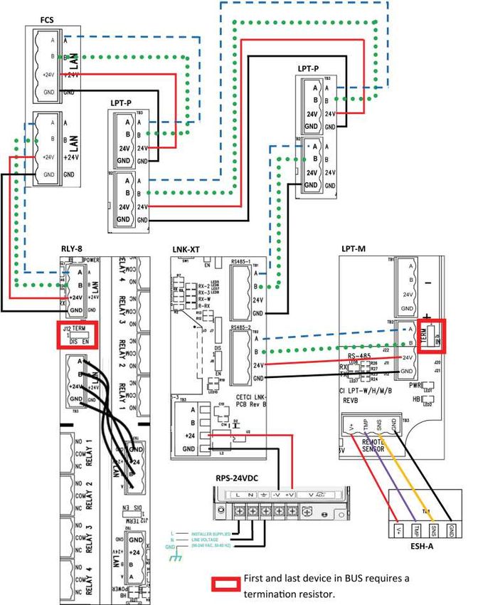
6.13 Wiring Digital Inputs (LPT-P & LPT-M Transmitters)
FCS LAN Terminal
The FCS provides 24 VDC (low voltage power) at the two LAN Terminals on the main board. Each LAN
terminal offers an A and B connection and together a maximum of 8 (FCS-8) or 128 gas channels (FCS), if
there are no configured analog inputs. Multiple digital transmitters must be connected to each other in
a daisy-chain fashion to ensure robust data communications. From one digital device to the next digital
device, A goes to A; B goes to B; GND goes to GND; 24V goes to 24V. In addition, the RS-485 bus must be
terminated at the beginning and the end of the wire run so the signal waves are absorbed rather than
reflected back.
NOTE: CETCI digital transmitters can be configured as 1, 2 or 3 channel systems depending on the
application requirements. Each channel occupies one of the available gas channels.
Four-conductor, 16 gauge, stranded wire / cable must be shielded when connecting to digital
transmitters. The voltage supplied by the FCS Controller to the remote digital transmitter should measure
approximately 24 VDC nominal at the transmitter(s). If this voltage is not attained after installation, the
wrong gauge wire may have been used or the wiring run is too long. 14 gauge wire should be used for
longer wire runs to minimize voltage drop.
NOTE: DO NOT USE solid-core wire for connection to wiring terminal strip. Any damage caused by using
solid-core wire will void warranty. Use stranded wire pigtails 18 awg within the enclosure to connect to
the circuit board. The rigidity of solid-core wire can pull a soldered terminal strip completely off a circuit
board and this will not be covered under warranty.
28 © 2019 All rights reserved. Data subject to change without notice.Rev. C | 2019.06 FCS - Installation Manual The LPT-P and LPT-M transmitter enclosures have several conduit entry locations. Under most local electrical codes, low voltage wires cannot be run within the same conduit as line voltage wires. Commonly used wire colours for positive, negative and signal VDC wires are: • Red for positive (+) 24 VDC power • Black for negative (-) Ground • White, Yellow or Green for signal (A and B) WARNING: Maximum distance information between the FCS and a remote digital transmitter can be found in that particular product’s Operation Manual. 6.14 Wiring LNK-XT Network Extender Peripheral Device The LNK-XT Network Extender Peripheral Device works as a signal booster, allowing transmission and receipt of gas readings over a larger total area. It extends the range of the Modbus® communication network allowing a longer distance between the Controller and the network of gas detectors. The micro controller quickly passes Modbus® information packets from the master side of the LNK-XT to the extension side, seamlessly without interruption. If the overall length of the wire run is more than 609 m / 2,000 ft, or if the area is electronically noisy, you will require an LNK-XT Network Extender to extend the range of the RS-485 network. The LNK-XT is a digital device and must be connected in a daisy-chain fashion. Up to six LNK-XT devices can be connected to the FCS. It is unlikely that an LNK-XT would be needed in an FCS-8 system. In the event that it is, one LNK-XT can be connected to the FCS-8. For more information about the LNK-XT, refer to the LNK-XT Peripheral Device Operation Manual. © 2019 All rights reserved. Data subject to change without notice. 29
You can also read