Applied Packaged Terminal Air Conditioner - 16" x 42" PDAN With Top-Mounted Hydronic Heat with R-410A Refrigerant
←
→
Page content transcription
If your browser does not render page correctly, please read the page content below
Installation & Maintenance Data                 IM 938-2

                                                                        Group: PTAC
                                                                        Part No.: 669275902
                                                                        Date: October 2009

Applied Packaged Terminal Air Conditioner
16" x 42" PDAN With Top-Mounted Hydronic Heat with R-410A Refrigerant

©2009 McQuay International
Table of Contents
Safety Information........................................................3         Operation..............................................................16-17
Inspection......................................................................3   Modes of Operation-Description........................17-19
Nomenclature................................................................4       Control Board Configuration..............................19-20
Introduction...................................................................5    Incremental Start-up Report Audit.........................21
Dimensional Data........................................................6           Equipment Start-up..................................................22
Wall Opening Requirements......................................7                    Controls Operating Instructions........................23-25
    Louver Frame Installation......................................7                    Digital Touchpad with Automatic Changeover from
    Wall Sleeve Extension Installation.........................7                        Cooling to Heating & Heating to Cooling............24
    Wall Construction Types........................................8                    Remote Wall Mounted Thermostats................25-29
Wall Sleeve Installation.........................................8-12               Wiring Diagrams..................................................30-32
    Thin Wall Construction.....................................8-10                     Digital Control Board With Standby Power.........31
    Thick Wall Construction....................................... 11                   Digital Control Board Without Standby Power....32
    Anchoring Wall Sleeve.........................................12                Scheduled Maintenance............................................33
Installation of Louvers..............................................12                 Equipment Protection from the Environment......33
    Electrical Service..................................................12              Recommended Spare Parts..................................34
Installation of Cooling Chassis...........................12-13                         Refrigeration Cycle .............................................34
Installation of Heat Section......................................13                Faults and Protection Codes
Installation of Room Cabinet...................................14                       PTAC/PTHP Control Board.................................35
Supply and Return Coil Arrangements..................14                                 Solid State Digital Controls
Controls                                                                                LUI Display Codes...............................................35
PDAN Digital Touchpad Control........................15-19                          Troubleshooting....................................................36-37
    Inputs & Outputs..................................................15
    Keys and Indicators Labels..................................15
    Display Function Legend.....................................15
    Wireless Remote Control (Option).......................15

       Now that you have made an investment in modern, efficient McQuay® equipment, its care and operation should
   be a high priority. For training information on all McQuay HVAC products, please visit us at www.mcquay.com and
   click on Training or phone 540-248-0711 and ask for the Training Department.

IM 938-2 / Page  of 40
Safety Information Inspection
Follow all safety codes. Wear safety glasses and When the equipment is received, all items should
work gloves. Use a quenching cloth for brazing be carefully checked against the bill of lading to be
operations. Have a fire extinguisher available. Follow sure all crates and cartons have been received. All units
all warnings and cautions in these instructions and should be carefully inspected for damage when received.
attached to the unit. Consult applicable local building If any damage is noticed, the carrier should make the
codes and National Electrical Codes (NEC) for special proper notation on the delivery receipt acknowledging
requirements. the damage. The carrier should also fill out a Carrier
Recognize safety information. When you see a safety Inspection Report. The McQuay International Traffic
symbol on the unit or in these instructions, be alert to the Department should then be notified. The unit nameplate
potential for personal injury. Understand the meanings should be checked to make sure the voltage agrees with
of the words DANGER, WARNING, and CAUTION. the power supply available. This unit is designed and
DANGER identifies the most serious hazards that will built for through-the-wall installation in either new
result in death or severe personal injury; WARNING or existing buildings. The self-contained refrigerant
means the hazards can result in death or severe personal system delivers cooling to the desired space. Heating is
injury; CAUTION identifies unsafe practices that can accomplished with a top mounted hydronic heating coil.
result in personal injury or product and property damage. Each conditioner consists of the following
Improper installation, adjustment, service, components:
maintenance, or use can cause explosion, fire, electrical 1. Cooling Chassis — Shipped separate in a single
shock, or other conditions which may result in personal carton.
injury or property damage. This product must be installed 2. Wall Sleeve — Shipped separate in a single carton
only by personnel with the training, experience, skills, or in a multi-pack of 15.
and applicable licensing that makes him/her “a qualified 3. Hydronic Heat Section — Shipped in a separate
professional HVACR installer.” carton.
4. Outdoor Louver — Shipped in a separate carton.
5. Room Cabinet — Shipped in a separate carton with
WARNING kickplate attached.
The installer must determine and follow all applicable
codes and regulations. This equipment presents hazards
of electricity, rotating parts, sharp edges, heat and weight. IMPORTANT
Failure to read and follow these instructions can result in This product was carefully packed and thoroughly inspected
property damage, severe personal injury or death. This before leaving the factory. Responsibility for its safe delivery
equipment must be installed by experienced, trained was assumed by the carrier upon acceptance of the
personnel only. shipment. Claims for loss or damage sustained in transit
must therefore be made upon the carrier as follows:
VISIBLE LOSS OR DAMAGE
DANGER Any external evidence of loss or damage must be noted
on the freight bill or carrier’s receipt, and signed by the
Hazardous Voltage! carrier’s agent. Failure to adequately describe such external
Disconnect all electric power including remote evidence of loss or damage may result in the carrier’s
disconnects before servicing. Failure to refusal to honor a damage claim. The form required to file
disconnect power before servicing can cause such a claim will be supplied by the carrier.
severe personal injury or death. CONCEALED LOSS OR DAMAGE
Concealed loss or damage means loss or damage which
does not become apparent until the product has been
CAUTION unpacked. The contents may be damaged in transit due
to rough handling even though the carton may not show
Use copper conductors only. Unit terminals are not designed
external damages. When the damage is discovered upon
to accept other types of conductors.
unpacking, make a written request for inspection by the
Failure to do so can damage equipment.
carrier’s agent within fifteen (15) days of the delivery date.
File a claim with the carrier since such damage is the
carrier’s responsibility.
IM 938-2 / Page of 40McQuay Model PDAN Product Nomenclature
Note: For Illustration purposes only. Not all options available with all models.
Please consult a McQuay Sales Representative for specific availability.
P DAN 2 009 E M A H A B A M A A E
Unit Type Warranty
P = PTAC A = Standard
E = Extended
Product Identifier X = Special
PDAN = Air Conditioner
Design Series
1 = A Design 1
SKU
2 = B Design 2
A = Stock
3 = C Design 3
B = Build to Order
4 = D Design 4
5 = E Design 5
Unit Size
007 = 7,000
009 = 9,000 Upgrade Packages
012 = 12,000 S = Seacoast
015 = 15,000 Y = None
017 = 17,000 (Cooling Only)
Voltage
A= 115-60-1 Power Connection
E= 208/230-60-1 L = Long Cord – 72" (Standard)
J= 265/277-60-1 S = Short Cord – 18" (Optional)
P= 208/230-60-1 w/stndby 115-60-1 Y = None
R= 265-60-1 w/stndy 115-60-1
T= 208/208-60-1
Brand Name Room Interface
M = McQuay
Cabinet Type
A = Top-Mounted Hydronic Flat top,
Refrigerant Bottom Return
A = R-410A
Heating Type Controls
E = Electric Heat Control Board Type
H = Hydronic PNUY = Premium, Non-Programmable, Unit Mounted
A = Hydronic w/Intermediate Electric PNWY = Premium, Non-Programmable, Wall Mounted
PNRY = Premium, Non-Programmable, Infared
Electric Heat PPUY = Premium, Programmable Unit Mounted
A = 2.5 Kw PAUY = Premium, Programmable with Auto
B = 3.5 Kw Changeover, Unit Mounted
C = 5.0 Kw PPWY = Premium Programmable, Wall Mounted
Y = None PPRY = Premium Programmable, Infrared
Hydronic Heat Type
S = Steam Top Mount (Normally Closed)
Damper Type
Damper Control
H = Hot Water Top Mount (Normally Open)
A = Automatic (Required for Hydronic Heating Subbase)
Y = None
A = Fresh Air Boost Fan
M = Manual
Y = No Damper
IM 938-2 / Page of 40Introduction
McQuay offers the most complete line of PTAC and self-contained refrigerant system delivers cooling to the
PTHP products for new construction projects and desired space. Heating can be accomplished with electric
exact replacements for our original Singer, Remington, resistance, with hydronic (water or steam), hydronic
American Air Filter and American Standard brand with intermediate electric resistance or with reverse
equipment, and models from other manufacturers. cycle technology (heat pump models only). Generally,
McQuay products feature our proven institutional grade an estimate for capacity selection is 35 BTUH per square
design and construction that allows you to benefit from foot of floor space (cooling) and 4 BTUH (1.25 watts)
the long life, reliability, and low sound levels, along per cubic foot (heating). The architect or engineer must
with higher energy efficiencies for lower operating costs. verify the selection. Note that the heat pump reverse
Plus, McQuay offers a nationwide network for original cycle generates approximately 10 BTUs per electrical
equipment replacements with local parts and service. watt as compared to 3.4 BTUs per watt with resistance
McQuay® Applied Packaged Terminal Air Conditioners electric heat. The unit will restart at its last setting after a
and Heat Pumps are designed and built for through-the- power interruption.
wall installation in either new or existing buildings. The
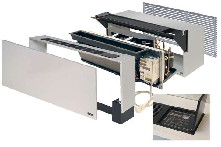
Figure 1. Exploded View of the 16" x 42" PDAN with Top-Mounted Hydronic Unit
Louver (Architectural)
Top-Mount Hydronic Heat Section
Cooling Chassis
Room Cabinet
16" x 42" Wall Sleeve
Removable Front Panel
Premium Digital Touchpad Control
IM 938-2 / Page of 40Dimensional Data
Figure 2. Unit dimensions – Chassis
Premium
Digital
Touchpad Control
Figure 3. Unit dimensions – Wall Sleeve, Cabinet & Louver
11⁄4" RECESS FOR ARCHITECTURAL LOUVER
“A” – IN. (MM) “D” – IN. (MM) “B” – IN. (MM)
ROOM CABINET WALL SLEEVE WALL THICKNESS
18 ⁄4 (476)
3
13 ⁄4 (349)
3
4 ⁄4–53⁄4 (121–146)
3
173⁄4 (451) 133⁄4 (349) 53⁄4–63⁄4 (146–171)
163⁄4 (425) 133⁄4 (349) 63⁄4 –73⁄4 (171–197)
153⁄4 (400) 133⁄4 (349) 73⁄4 –83⁄4 (197–222)
143⁄4 (375) 133⁄4 (349) 83⁄4 –93⁄4 (222–248)
133⁄4 (349) 133⁄4 (349) 93⁄4 –103⁄4 (248–273)
123⁄4 (324) 133⁄4 (349) 103⁄4 –113⁄4 (273–298)
113⁄4 (298) 133⁄4 (349) 113⁄4 –123⁄4 (298–324)
103⁄4 (273) 133⁄4 (349) 123⁄4 –133⁄4 (324–349)
103⁄4 (273) 143⁄4 (375) 133⁄4 –143⁄4 (349–375)
103⁄4 (273) 153⁄4 (400) 143⁄4 –153⁄4 (375–400)
103⁄4 (273) 163⁄4 (425) 153⁄4 –163⁄4 (400–425)
103⁄4 (273) 173⁄4 (451) 163⁄4 –173⁄4 (425–451)
Standard Size Wall Sleeve
Note: Electrical rough-in should be located behind kickplate
(removable front) and below wall sleeve.
Wall Thickness
11⁄2" “A”
(38mm) 52" “B”
(1320mm) 11⁄4" (32mm)
27⁄8"
(67mm)
191⁄2" Wall Space For Piping 16"
(495mm) 91⁄8" “D”
Rough-in (232mm) (406mm)
(Typ. R.H. & L.H.) 51⁄2"
3" (140mm)
7/8"
(76mm) Min.
(22mm)
3" Kickplate (Removable
(76mm) 3"
Front) 7/8" 15⁄16" 15⁄8" (76mm) Min.
(22mm) (33mm) (41mm) Kickplate Height
IM 938-2 / Page of 40Figure 4. Louver Frame Dimensions
WARNING
Residential and institutional cleaning compounds can cause
permanent damage to the packaged terminal unit. To avoid
damage to unit controls and heat transfer surfaces, do not
spray cleaning compounds onto the discharge grille, return 183/16"
air opening, or unit controls. Normal cleaning can be accom-
plished by wiping the unit surface with a damp cloth. When
using cleaning compounds on carpets, floors or walls, turn 423/16"
the unit off to avoid drawing potentially damaging vapors into
the package terminal unit.
163/16"
Wall Opening Requirements
443/16"
3
3 /4"
When roughing in the opening for the wall sleeve, make
certain there is sufficient clearance from the walls and
floor. The wall sleeve should be positioned a minimum of Note: Wall Sleeve rough opening when using a Louver Frame must
be 165/8" x 425/8"
5/8" in from the room side finished wall to accommodate
the room cabinet. A minimum distance of 3" above the
finished floor is required for return air.
Wall Sleeve Extension Installation
Wall sleeve extensions are shipped in a separate carton
The rough opening should measure 16¼" high x 42¼"
and tagged to match the proper unit. Be sure to check
wide. Before installing the unit, check the wall opening
tagging of the extension against that of the unit. Install
to be sure the wall sleeve will slide into the opening
the wall sleeve extension as follows:
unobstructed and there is allowance for a 1/8" to 1/4"
1. Position the extension with standard wall sleeve
pitch inside to outside for proper sleeve drainage. For
so proper alignment with drain and mounting holes is
masonry walls, a lintel must be used to provide support
achieved.
over each opening.
2. Place a bead of caulk around the perimeter of the
When using a louver frame, the opening must measure
wall sleeve and another bead around the mating
165/8" x 425/8". Louver frames should be used for
side of the wall sleeve extension so that the joint
panel wall and thin wall applications to assure positive
is watertight. Do not permit caulking to block the
anchoring to the wall (Figure 4).
weep holes. Be sure to use a resilient caulking such
The opening must start 4" above the finished floor
as silicone.
(including carpeting) to provide proper return air.
3. Assemble the wall sleeve extension to the wall
Louver Frame Installation sleeve. Clean out weep holes to assure proper
When a louver frame is used, it must be installed prior drainage.
to, or at the same time, as the wall sleeve, and it must be 4. Continue wall sleeve installation according to
level and square. instructions on page 8.
1. Apply caulking compound on the surfaces of the lou-
Figure 5. Wall Sleeve Extension
ver frame’s four flanges which will come in contact
with the wall. Add caulking as required for weather 24"
tight seal. As Required Room Side
2. Insert the sleeve of the louver frame into the wall
opening from the exterior of the building and apply
firm pressure so that the caulked frame flanges are
snug against the exterior of the building. Secure the
louver frame to the wall if desired. 16"
3. Secure the louver frame to the wall through the sides Air Splitters
and top. Never secure the frame through the bottom 111/8"
as it may cause leaks.
If the louver frame is to be installed in a panel wall, it 24"
should be installed at the same time as the wall sleeve. 42"
Wall Sleeve Extension
CAUTION 67/8"
DO NOT drill holes in the bottom of the wall sleeve as it will
cause leaks.
IM 938-2 / Page of 40Wall Construction Types Wall Sleeve Installation
Figure 6. Panel Wall (Thin) Construction Thin Wall Construction
The standard wall sleeve is designed to be easily installed
Steel Studs
in a variety of wall constructions. For panel wall and thin
wall construction, it is recommended that the optional top
angle be used and the wall sleeve be supplied with a turned
down flange (see Figures 9, 10 & 11).
Concrete The recommended procedure for installing units in panel
Pillars
wall and thin wall construction is as follows:
1. Clean the opening of all debris that may interfere with
installation.
161/4" x 421/4" Floor 2. Recess the wall opening so that the louver is flush with
Wall Sleeve
Rough Opening or
the exterior of the building. The center of gravity is ap-
165/8" x 425/8" When using a proximately 103⁄4" (273mm) from the rear face of the
Louver Frame standard wall sleeve. If a subbase is not used, field sup-
(See page 7 for Installation)
port must be provided up to the center of gravity. This
support can be metal, wood or concrete.
Figure 7. Frame and Brick Construction 3. Level wall sleeve side to side and pitch to outside 1/8"/ft.
to assure proper sleeve drainage to outside. Anchor with
16" x 42"
Wall Sleeve appropriate fasteners. Use holes provided (see Figure 15,
page 12) or drill additional holes as required to secure
firmly.
Lintel
(by others)
161/4" High CAUTION
Do not drill holes in the base of the wall sleeve. Use shims
between the wall and the wall sleeve to prevent wall sleeve
distortion during anchoring.
421/4" Wide Wall
Sleeve Rough Opening
4. Caulk the wall sleeve to the wall opening on both the
inside and outside perimeter. This can be done from the
inside of the building. Be careful not to plug the weep
holes.
Figure 8. Masonry Wall (Thick) Construction
Note: When using recessed louver wall sleeve, level and plumb wall
Room Side
Lintels (by others) sleeve using the top and sides of the sleeve and the chassis slide rails.
DO NOT level using the bottom of the wall sleeve as it has a built in
pitch to drain.
Wall Sleeve Extension
(See page 7 for Splitters
Installation) 16" x 42" Wall Sleeve
IM 938-2 / Page of 40Figure 9. 16" x 42" wall sleeve with continuous flange and drip edge
X*
Flange location (from outdoor side of sleeve)
is factory provided in increments of 1/8"
42" D**
Flange Height
(Standard = 1-1/4")
Louver Mounting Holes 16"
Drip Edge
Figure 10. Wall sleeve installation for thin wall Figure 11. 16" x 42" wall sleeve with optional leveling
construction legs and continuous flange
B**
13-3/4"
X* 42"
Insulation Wet Panel
Window Stool Optional
Continuous 11/4"
1-5/8" Metal Stud 16" O.C. Flange
16"
3-1/2" Thick
Batt Insulation
X*
D**
Hydronic Heat Optional
Coil Section Outdoor Side of
Leveling Leg
Sleeve
Cabinet
Leveling Leg 63/8"
to Support
Note:
Given dimensions are standard.
Notes:
** See table on page 6, for dimensions “D” and “B”.
* Dimension “X” is field determined or specified. Angle is factory welded at given dimension when option is designated.
IM 938-2 / Page of 40Wall Sleeve Installation 2. Position the wall sleeve into the wall so that it is flush
with the exterior wall. Important: If the wall sleeve
Thin Wall Construction has been installed into a thick wall, make certain the
Applications utilizing field supplied louvers require ad- wall sleeve protrudes into the room a minimum of
ditional considerations: 11/8" (29mm) beyond the finished wall surface. This
1. Louvers supplied by others must have 70% free area is to accommodate the heat section and room cabinet.
or a pressure drop not exceeding 0.05 in. w.g. (12.45 The center of gravity is 103/4" (273mm) from the rear
Pa) at 300 fpm (1.524 m/sec) face velocity, and a blade face of the standard wall sleeve. If no subbase is being
design that will not cause recirculation of air. employed, adequate support for the wall sleeve up to
2. McQuay does not warrant the rain and water leakage the center of gravity must be provided at the job site.
resistance of its equipment when used with louvers by This support can be wood, metal or concrete.
others. 3. Level wall sleeve side to side and pitch to outside 1/8"/
3. All louvers by others must be approved by McQuay ft. to assure proper sleeve drainage to outside. Anchor
engineering prior to installation. with appropriate fasteners using holes provided (see
Figure 12 illustrates a typical installation using a field Figure 15, page 12), or drill additional holes as required
supplied, continuous louver. This method is for illustra- to secure firmly.
tion purposes only. Other variations may be employed as
long as they meet McQuay's louver specifications listed CAUTION
above and so long as adequate wall support is achieved. Do not drill holes in the base of the wall sleeve. Use shims
All structural supports and fasteners (except the optional between the wall and the wall sleeve to prevent wall sleeve
top angle and turned down flange) are field supplied. distortion during anchoring.
Installation of wall sleeves with continuous louvers is
very similar to that of applications with factory furnished 4. Caulk the wall sleeve to the wall opening on both the
louvers. Assuming the louver meets the McQuay’s criteria, inside and outside perimeter. This can be done from the
as stated previously, proceed to install the wall sleeve as inside of the building. Be careful not to plug the weep
follows: holes.
1. Clean the opening of all debris that may interfere
with installation.
Figure 12. Wall sleeve installation using top angles and field supplied continuous louver
133⁄4"
(349mm)
Wall
Frame
11⁄4" By Others
42" (38mm) Insulated
(1069mm) Panel
Optional Optional
Wall
Top Angle
Sleeve Top Angle
Wall
Sleeve
Turndown Resilient
16" Flange Caulking
(406mm) (See Detail) (see Note 2)
X* 16" Wall Sleeve
Outside Edge (406mm) Outside Louver
Optional of Sleeve By Others
3" Min. Subbase
(76mm)
Resilient
Turndown
Caulking
Flange
Finished Floor (see Note 2)
101⁄2" Including Carpet Min. 37⁄8"
(267mm) (98mm)
Max.
Supports By Others
1" (2 Req’d.)
(25mm)
Insulated Panel
Notes:
1. Caulk entire perimeter of wall sleeve after installation.
2. Seal area between louver and wall sleeve to prevent condenser air recirculation.
3. Dimensions shown in table on page 6 do not apply to this application.
* Dimension “X” is field determined or specified. Angle is factory welded at given dimension when option is designated.
IM 938-2 / Page 10 of 407. Caulk the wall sleeve to the wall opening on both the
Wall Sleeve Installation in-side and outside perimeter using a resilient, non-
Thick Wall Construction hardening caulk such as silicone. Be careful not to
A heavy-gauge, corrosion resistant wall sleeve is provided plug the weep holes.
for each unit. The wall sleeve is either shipped in a separate
carton or shipped in a multi-pack of 15. Figure 13. Wall sleeve installation using brickstops
Typical installation for masonry walls is shown in Figure
13. The recommended installation procedure for this type
of construction is as follows:
1. Clean the opening of all debris that may interfere with B
installation. Wood Stool
2. Be sure the unit’s center of gravity falls within the load
bearing surface of the wall. The center of gravity for
4"
Room
the unit is approximately 103⁄4" (273mm) from the rear Cabinet
Brick Wall Sleeve
edge of the wall sleeve. If the center of gravity is not
2'-4"
1'-4"
Optional
within the load bearing surface, then additional support D A 2'-61⁄2"
Continuous
such as wood, metal or concrete must be provided in Flange
the field.
Outside
3. Place a thin pad of soft mortar on the bottom of the Louver
Finished
opening. Important: Make certain the wall sleeve 1" Floor
protrudes into the room a minimum of 11⁄8" (29mm)
beyond the finished wall surface to accommodate the 7-1⁄4"
Exposed Projection
heat section and room cabinet. Be sure to recess the wall Concrete Slab
sleeve enough to accommodate outside louver. This
recess is 3/8" (9.5mm) for stamped louvers and 11⁄4" Brick
Casement Window with
(32mm) for architectural louvers. The louver should Insulating Clear Glass
be flush to exterior surface when completed.
4. If a brickstop is employed (as shown in Figure 5), slide
the wall sleeve into the wall until the brickstop contacts
the exterior bricks, as illustrated below. If a brickstop Figure 14. Standard 16" x 42" wall sleeve with brick
is not used, slide the wall sleeve in the wall so that stop
it extends into the room a minimum of 11⁄8" (29mm) D
beyond the finished interior wall surface. This allows X
Optional Brickstops
room to attach the heat section and room cabinet. The 42"
wall sleeve should also be recessed enough to accom- (1067mm)
modate the outside louver. Level wall sleeve side to
side and pitch to outside 1/8"/ft. to assure proper sleeve
drainage to outside.
5. After the mortar has dried, remove the masonry sup- 16"
port from the wall sleeve. Note: The wall sleeve is not Wall Sleeve (406mm)
intended to replace the lintel.
Outside Edge
6. Anchor with appropriate fasteners (as shown in Figure of Sleeve
15, page 12). A 5/16" (8mm) hole is provided on each
side, 2" (51mm) down from the top and 2" (51mm)
1-1⁄4" (32mm)
in from the rear of the wall sleeve. It may necessary
to drill additional holes in the wall sleeve to firmly Notes:
secure it. 1. For dimensions B and D, see table on page 6.
2. Dimension “X” is “as required” and is usually sent to the factory
CAUTION to be welded during wall sleeve fabrication.
3. Caulk entire perimeter of wall sleeve after installation.
Do not drill holes in the base of the wall sleeve. Use shims
4. Wall sleeve to extend a minimum of 1-1/4" past finished
between the wall and the wall sleeve to prevent wall sleeve
sheetrock.
distortion during anchoring.
5. Wall sleeve should be installed recessed 1-1/4" from face of brick
so that when louver is installed it is flush with face of building.
IM 938-2 / Page 11 of 40Anchoring Note: Discharge air restrictions include, but are not
limited to:
Anchoring the wall sleeve is accomplished as shown
in Figure 15. Use the rubber isolation washers with • Vegetation
the fasteners to minimize sound transmission from the • Concrete walls or barriers
equipment to the wall, at the point of contact. A 5⁄16" • Overhangs that do not allow discharge air to rise
(8mm) hole is provided on each side, 2" (51mm) down • Installation of bug screen of any kind
from the top and 2" (51mm) in from the rear of the wall • Outdoor louvers by others unless approved by the
sleeve. It may be necessary to drill additional holes in factory
the wall sleeve to firmly secure it.
WARNING
CAUTION Improper electrical supply can cause property damage,
severe personal injury or death.
Do not drill holes in the base of the wall sleeve. Use shims
Electrical Service
between the wall and the wall sleeve to prevent wall sleeve
distortion during anchoring.
All wiring should be in accordance with all local and
Figure 15. Anchoring the Wall Sleeve National Electrical Code requirements.
Units are supplied with an attachment cord and plug which
Rubber exit from the bottom of the conditioner on the control side.
Isolation
Washer
The cord for 115V, 208V and 230V has a usable length of
72" (1829mm) from where it exits the conditioner. The use
of extension cords to increase the length of the plug/cord
Expansion Molly or Wood set is not recommended.
Screw
Anchor Bolt Toggle Bolt
The attachment plug size should be used to determine the
circuit ampacity and overcurrent protection. Time delay,
overcurrent protection devices are recommended to pre-
Do Not Drill Holes in Bottom of
Sleeve (Except for Internal
Cripple Stud vent unit damage and to avoid nuisance tripping.
Drain Kit) Outlets are generally located beneath the conditioner, on
Main Stud
or recessed in the wall so it is concealed by the conditioner
Note: all anchoring hardware field supplied overhang and kickplate.
Installation of Louvers Cooling Chassis Installation
1. Remove louver from its shipping carton and also the
Correct installation of the cooling chassis is extremely
hardware package for mounting the louver.
important to insure the proper operation of the unit. Install
2. Remove outside weather plug and weather panel
the chassis as follows:
from wall sleeve.
3. Make a temporary handle by looping a piece of
WARNING
flexible wire or heavy cord through the louver. This
enables the installer to keep a firm grasp on the The chassis weighs approximately 150 lbs. Use blocking
louver when installing from inside the room. and lifting devices. Do not raise over any body parts.
4. Push the louver through the opening at the rear of
1. Remove outer carton and inspect for any shipping
the wall box, then pull the louver back to the wall
damage. Report any found to the carrier.
sleeve flange so that the louver studs pass through
2. Check nameplate data on chassis to insure that the
the holes in the flange.
correct job site distribution has been made with
5. Attach washers and nuts and secure louver in place.
respect to cooling capacities. Generally, corner
6. If the cooling chassis is not to be immediately
rooms require larger capacities.
installed, replace the weather panel.
3. Remove chassis from carton by pulling evenly on
IMPORTANT substantial portion of unit.
Air flow required for PTAC units must not be restricted CAUTION
by exterior plants or walls. Plants or shrubs must not
be planted in close proximity to the outside grille of the Do not pull on evaporator fan housing, control box or
PTAC unit. Vegetation planted too close to grilles will compressor.
cause discharge air to be recirculated, thereby increasing Do not lift by pulling on the tubing. Tubing can crack or
electrical consumption. Warranty will be voided if it is bend damaging the unit.
determined that the compressor life is shortened from
overheating due to close proximity of outside obstructions.
IM 938-2 / Page 12 of 404. If wall sleeve has been previously installed, remove
temporary weather panel.
Heat Section Installation
The heat section is designed to be “snapped” into the top
5. Check all fasteners to make certain they have not
of the wall sleeve (Figure 16). There are four square holes
come loose during shipment. Do not loosen nuts
provided in the wall sleeve, two on each side, for coil attach-
holding down compressor; they are set at the factory.
ment. To Assemble the heat section to the wall sleeve:
6. Do not lubricate motors before start-up. Motors are
1. Unpack the heat section and inspect for any shipping
factory lubricated. Consult “Scheduled Maintenance”
damage. Report any damage found to the carrier.
section on page 32 for lubrication instructions.
2. Check the heat section against the plans to make certain the
7. Place Tinnerman clips from bag onto wall sleeve.
coil supplied has the connections match the specifcations.
Clips and mounting screws are enclosed in a bag
3. Firmly attach the heat section to the wall sleeve by lining
attached to the top of the condenser coil cover.
up the heat section hooks with the square holes supplied
8. If louver has not been previously installed, connect
in the wall sleeve. Snap the heat section in place by
to wall sleeve as described above.
exerting pressure downward.
9. If louver is supplied by others, as illustrated in
4. The valve is always connected to the supply side of
Figure 12, page 10, be sure to install foam type
the coil. There are seven possible coil arrangements
gaskets on all sides of the condenser coil to prevent
available. Each is shown on the next page. Select the
recirculation or bypass of condenser air.
illustration below that matches the coil supplied and pipe
10. Slide chassis into wall sleeve until firmly seated
it according to the illustration. Install valve and other
against weather seals of wall sleeve. Caution: Do
accessories including air vents, steam traps, stop balance
not push on coil surface or control box cover. Make
valves, etc., as specified by the design engineer.
sure the compressor tubing does not catch when
5. For valve installed on right side of the unit, make elec-
inserting chassis.
trical connection to matching cap extending from the
11. Secure chassis to wall sleeve with four (4) sheet
control box. For left side valve, make electrical connec-
metal screws packaged with the Tinnerman clips.
tion to cap mounted to left side of chassis.
12. Plug electrical cord into receptacle. Excess cord
Note: When the heating medium is steam, the supply
should be coiled up neatly and stored in the
connection should be attached to the uppermost tube
conditioner.
and the return to the lower tube. The coil is pitched in the
13. Set the manual damper operator in open or closed
casing to allow drainage of condensate.
position as desired. On units equipped with the
When the heating medium is hot water, the supply
optional electric fresh air damper, set for “AU”
connection should be made to the lowermost tube and
or "CL" in the Configuration Mode. In “AU,” the
the return to the uppermost tube. Hot water coils
damper is open whenever the indoor fan motor is
should be “flooded” to minimize air entrapment.
running (AU is Auto and CL is Closed).
6. The Heat Fan Lockout (HFLO) must be installed on the
14. Set the indoor fan mode for off cycle on the PC
return piping of the hot water coil and after the steam
board for the off cycle selection of 10, 20, 30
trap for steam heat units. The Factory provides a sensor
minutes or 1 hour off cycle time. The fan will operate
snap-on bracket that will fit standard 5/8" OD copper.
for 2 minutes and shut down for the selected off
Sensor mounting brackets for all other pipe sizes or
cycle period. For continuous fan operation, the fan
materials must be field supplied.
mode selection on the touchpad or remote thermostat
must be set to continuous or on. When the room Figure 16. Installing the Cooling Chassis and Hydronic
thermostat is in the cycle or auto mode, it will cycle Heat Section
the indoor fan when there is a call for heating or
Hydronic Heat Section
cooling. See page 28 for jumper placement details.
15. Set the temperature limiting feature to the desired
range of thermostat operations. As shipped, the
range is 60°F to 85°F.
16. Replace the air filter and front panel. Cooling
17. Connect the low voltage valve wires with the Chassis
Molex connection to the valve. Factory
Supplied
Holes (2)
Wall Sleeve Damper
Actuator
IM 938-2 / Page 13 of 40Installing Room Cabinet 4. Loosen the four (4) wing nuts on the kickplate and
The room cabinet is the last piece to install. The following adjust the kickplate the required distance to the floor.
instructions assume all components (wall sleeve, heat sec- 5. Tighten the wing nuts firmly.
tion, louver and chassis) have been installed, piped and 6. Wipe any smudges or dirt off the room cabinet using
anchored. All major room construction should also be a mild cleaner and a soft cloth.
complete so as not to damage the room cabinet after it has Figure 17. Room Cabinet Detail
been installed. Attaching the room cabinet can be com-
pleted as follows:
1. Firmly grasp the room cabinet and lift it over the
heat section. There are notches in the back flanges of
the room cabinet that rest on the wall sleeve to assure
it is centered.
2. Align the notches of the room cabinet on the wall
sleeve and firmly push the cabinet downward until it
seats on the wall sleeve (see Figure 17).
3. Screw the cabinet to the wall using the screws
provided. There are two (2) screw holes provided on
each side located on the inner flanges of the room Screw slots on back of cabinet for
Notch on back of cabinet to set
cabinet. on wall sleeve
securing to wall (2-each side)
Supply and Return Coil Arrangements
Steam Hot Water
Figure 18a. Left-hand supply and return Figure 18e. Left-hand supply and return
Supply
Return
Return Supply
Figure 18f. Right-hand supply and return
Figure 18b. Right-hand supply and return
Return
Supply
Supply
Return
Figure 18c. Right-hand supply, left-hand return Figure 18g. Left-hand supply, right-hand return or
Right-hand supply, left-hand return
Supply
Return
Return
or Return
Supply or
Supply
Figure 18d. Left-hand supply, right-hand return
Supply
Return
IM 938-2 / Page 14 of 40PDAN Digital Control Display Function Legend (Also see page 34)
Tr = Room Temperature
Figure 19. Digital Control rT = Remote Thermostat Control
tP = Touchpad Control
t = Time
Ts = Temperature Setpoint
rF = Room Freeze Condition
Figure 20. Digital Control Indicators
LED
2-Digit Display
9- LED
Application Indicators 7- Push Buttons
The PTAC Digital Control is used to control a PTAC Unit
that includes both an integral air conditioner and a source
of heat.
The Digital Control is operated with a Touchpad.
Inputs Wireless Remote Control (Optional)
• Indoor Coil Sensor (ICS)
• Indoor Air Sensor (IAS)
• Outdoor Air Sensor (OAS)
• Inputs from Remote Thermostat, RBGYW
• Heat Fan Lock Out Sensor (HFLO)
• Power Supply, 24VAC
Outputs The Remote Consists of 10 Push-buttons
• Compressor output (COM)
• Power:
• Outdoor Fan (FAN)
Functions same as ON/OFF button on the touchpad.
• Indoor Fan (BLOWER HI, BLOWER LO)
• Damper Control (DAMPER)
• Sleep:
• Hydronic Valve (HYV)
Functions same as SLEEP button on the touchpad.
Mode Buttons
Keys and Indicators Labels • Heat, Cool, Cool/Dry, Fan:
ON/OFF, FAN SPEED, FAN MODE, Performs same function as the MODE button on the
SLEEP, MODE touchpad, and allows user to select specific mode of
7 Push Buttons
Temp buttons: Arrow Labels for
operation using only one button.
Temp UP and DOWN
SLEEP, COOL, COOL/DRY, FAN, • Temp Buttons +, –:
9 LED Indicators
HEAT, HIGH, LOW, CYCLE, CONT. Functions same as buttons on touch pad, allowing user to
LED 2 Digit Displays change the setpoint.
• Fan Speed Buttons (High & Low):
Performs same function as the FAN SPEED button on
the touchpad, allows user to select specific speed using
only one button.
Remote must be aimed in a line of sight of the window
in upper right corner on the front panel, at less than a 45o
angle from center of the window.
The control board will beep when any button is pressed
on the Remote control to confirm signal.
IM 938-2 / Page 15 of 40Controls Temperature Range
The maximum operating temperature range is selectable
Standard Digital Touchpad Control via the Touchpad and is 60°F to 85°F, with the limits
included. The Remote Thermostat selectable operating
Operation range is 60°F to 90°F with limits included. The range is
Memory Recall set in the Configuration Mode.
The digital control shall start with the last settings used
prior to power down. These settings are saved in a non- Indoor and Outdoor Fan Operation
volatile memory. Factory set mode is OFF. The indoor fan can be set to operate on High or Low
speed with the Fan Speed Button on the touchpad. It
On/Off Triggering can also be set for Continuous or Cycle operation on the
Control can be turned On/Off via the Local User touchpad. When set for Continuous, the “CONT” LED
Interface (LUI), Remote T’stat, or Sleep feature. The will be on and the fan will run continuously. When set
control will show the temperature set point when the for Cycle, the “CYCLE” LED will be on and the fan will
mode is Cool, Cool Dry, or Heat. The display will be turn on at a call for heat or cooling.
blank in Fan mode.
1. On/Off triggering with LUI
Control shall turn On or Off when the On/Off
Fan Cycle Operation
On a call for Heating or Cooling, the indoor fan and
button is pressed in LUI. Once turned on control
the heating source or the compressor will be activated.
shall start on the last mode used before it was
When the call is satisfied and the heating source or the
turned Off.
compressor is deactivated, the indoor fan will repeatedly
2. On/Off triggering with the Remote T’stat
run for 2 minutes on and the number of minutes selected
Control shall be turned On if it was Off from the
on the PC Board off, until the next cut-in cycle. The
Remote T’stat when it is set up to be controlled by
number of cycles with timing as described above is
a Remote T’stat. A call for heat or cool from the
determined based on the OFF FAN CYCLE jumper
Remote T’stat will be used to turn the control on.
setting on the unit control board.
Control remains on until manually turned Off.
3. On/Off triggering with the Sleep feature
Sleep feature works in combination with the Timer Remote Thermostat Mode
setting. Sleep time setting shall be user adjustable The unit can be jumper configured on the unit control
from 1 to 15 hours via the Touchpad. The timer board to take commands from a Remote Thermostat. The
will count down and when it reaches “0” it will Remote Thermostat will call for Heat and Cool through
turn the control Off if control was previously On the electronic controller.
and vice versa, if it was Off it will turn On after
time expires. As mentioned in protections section 1. The Remote T’stat will control through the unit
of this spec the Sleep operation is overridden by control board the work of the compressor, indoor and
room freeze protection. outdoor fans, the reversing valve, and the heat
control valve.
Control Off 2. In Cool mode the compressor and condenser fan
When the control is in the Off Mode, relay outputs will shall turn on when "Y" signal is high.
be disabled with the exception of the indoor fan (blower). 3. Cold start feature (see Modes of Operation – Cold
It will stay on to meet the Hot Keep specification. Start), Cool dry mode (see Cold Dry Mode) and
Indicator LED’s are all off. Sleep feature (see Sleep Feature) are not available
in Remote T’stat cool mode
IM 938-2 / Page 16 of 40Controls Modes of Operation-Description
Standard Digital Touchpad Control Standard Digital Touchpad Control
Cool Mode
System Select Operation Using Remote In Cool Mode, the compressor will start if the
Thermostat temperature at the space temperature sensor is 1°F
System will run in Heat mode and engage certain outputs or higher than the set point. It will stop if the space
based on the system selection (jumper) as described temperature sensor is 2°F or lower than the set point,
below (see Premium Digital Control Board Wiring subject to timing requirements.
Diagram on page 29). In the Cool Mode, the indoor fan will operate according
to the user settings for Fan Mode – Continuous or Cycle
Notes: and Speed.
1. Hot start and Sleep features are not available in Remote T’stat
heat mode.
2. Control’s operation is subject to its own protection features when Cold Start
controlled by a remote thermostat. Cold start is initiated when the control has not called
3. Indoor fan mode and the speed will default to “cycle” and for cooling for more than two (2) hours or during
“high” when unit is controlled by remote thermostat. a power-on-reset. During cold start, the set point is
4. The indoor fan is turned on when G signal is high. When there lowered by 4°F (Tset-4°F) if the differential calls for
is no signal on G terminal then the indoor fan will be turned off.
cooling. The unit will operate in cold start until the new
set point is satisfied (+ or – 1°F) or until the unit has run
Control Lockout Feature in cold start for at least 20 minutes. After one or both
The control is placed in a lockout mode of operation
conditions are met, the set point will be reset to the user
when Mode button is held pressed for 10 seconds.
setting and the unit will run in the regular cool mode.
Display will show “LC” to confirm Lockout Mode has
The indoor fan will operate according to the user settings
been entered. Once in this Lockout Mode the control
for mode – Continuous or Cycle and Speed.
board will not take any commands at all. In Lockout, unit
Cold start is not available with the Sleep feature.
will continue to operate with the settings just prior to
Lockout Mode. This means the touchpad will no longer
Sleep Function
be able to pass commands to the control. User’s set point
Sleep time is adjustable by the user from 1 to 15 hours in
will normally be displayed. Any button pushed will bring
one (1) hour increments in a closed loop. The sleep time
“LC” on display for five seconds.
is adjusted and set via the touchpad and by pressing the
To exit the Lockout Mode and return to normal (regular)
Sleep Button repeatedly. On the touchpad, the display
mode of operation, press the Mode button for 10
will show the set time in numbers for five (5) seconds.
seconds. Display will show “nL” for five seconds to
Before the sleep time expires, the setting can be adjusted
confirm normal mode has been resumed.
above the number of hours passed by pressing the Sleep
Button. Pressing the On/Off Button can terminate the
Sleep Mode.
A changeover from Heat to Cool or another Mode will
reset the Sleep Timer.
The Sleep Function will raise the temperature setting
one degree fahrenheit every half hour for two hours for
a maximum of four degrees. Changing the Mode or a
changeover from Heat to Cool will reset the Sleep Timer.
The Sleep Function will be deactivated by pressing
the power-on-reset or any button (except sleep) on the
touchpad or the Remote Control.
IM 938-2 / Page 17 of 40Modes of Operation-Description
Standard Digital Touchpad Control
Cool Dry Mode Figure 22. Zone B
Select the Cool Dry Mode when the standard Cool Mode On
does not provide sufficient dehumidification. In Cool Dry Compressor
Mode, the unit must run in Cool Mode for 12 minutes Off
or until the temperature differential between the room t
temperature and the set point is less than 2°F. This will 8 mins. 4 mins.
also occur after a Cold Start or a Mode change from Cool
to Cool Dry. During this time, the fan will operate in the On
Mode and Speed selected. Low Fan
Until one or both of the above conditions are met, Off
t
the control will determine which Dry Mode (Zone) is
initiated based on the temperature differential between 30 secs. 30 secs.
the room temperature (Tr) and the temperature set point Figure 23. Zone C
(Ts):
On
Note: Cool Dry is not available with Sleep Function. Compressor
Off
Figure 21. if Tr - Ts > 4°F, operation will be in Zone A t
Figure 22. if 2°F < Tr - Ts < 4°F, operation will be in 6 mins. 6 mins.
Zone B
Figure 23. if 0°F < Ts - Ts < 2°F, operation will be in On
Zone C Low Fan
Figure 24. if Ts - Tr > 5°F, operation will be in Zone D Off
The other temperature ranges are dead bands for zone t
stability. 30 secs. 30 secs. *
* = Zone Determination Time
Figure 21. Zone A
Compressor Figure 24. Zone D
On
On Fan
Off
t
Off
t
Low Fan
On
Off
t On Compressor
*
12 mins.
* = Zone Determination Time Off
* t
12 mins.
* = Zone Determination Time
IM 938-2 / Page 18 of 40Modes of Operation-Description
Standard Digital Touchpad Control
Heat Mode Control Board Configuration
Unit will call for heating based on the type of the heat To enter the Configuration Mode, simultaneously press
source it has: heat pump in reverse cycle or electric. the Up and Down buttons for 5 seconds. To change
1) Hot Start settings, press the Up or Down button. To move from one
Hot Start is possible when the control has not called for screen to another, press the Mode button.
heat in more than (2) hours or during power-on-reset. To exit Configuration Mode, press the Up and Down
During Hot Start, the user’s set point is raised 4°F (Ts + buttons simultaneously for 5 seconds or control will
4°F). The unit will only call for heat if room temperature automatically exit in 15 seconds.
differential calls for heat. Settings within the Configuration Mode are as follows:
The unit will continue in Hot Start Mode until the
new set point is satisfied (with a 1°F differential) Temperature Scale
or unit has run for at least 20 minutes. After one or To view the Temperature Scale Screen, press and hold
both conditions are met, the set point will be reset the Up and Down buttons for 5 seconds. The temperature
to the user’s setting and the unit will run in regular scale will be displayed. The default setting is degrees
heat mode. Hot start is not available with the Sleep fahrenheit and by pressing either the UP or Down button
feature. The fan will operate per the Fan Mode and can toggle to Degree Celcius.
Speed setting.
Temperature Limit Settings
2) Hot Keep To advance from Temperature Scale Setting, press the
When the water valve closes, the indoor fan will operate Mode button once. To set the Cool Minimum set point,
per the user mode (Constant or Cycle) and speed setting. press and hold Fan Cycle button and adjust the setting
with the Up or Down buttons. The minimum setting is
Sleep Function 60°F.
Sleep time is user adjustable from 1 to 15 hours in To set the Heat Maximum set point, press and hold Fan
one (1) hour increments, in a closed loop via the touch Speed button and adjust the setting with the Up or Down
pad, by pressing the Sleep button repeatedly. The buttons. Maximum setting is 85°F.
Sleep Mode can be terminated by pressing the The Display will show the upper operating limits first.
On/Off button. The default settings are Cool min. = 60°F and Heat max.
The Sleep Function will lower the temperature setting = 85°F.
one degree fahrenheit every half hour for two hours for
a maximum of four degrees. Changing the Mode or a Setting The Outside Air Damper
changeover from Heat to Cool will reset the Sleep Timer. To view Damper Setting press the Mode button once. To
The Sleep function will be deactivated by Power-on- adjust the damper setting (AU or CL), press the Up or
reset, or by pressing any button on the Touchpad except Down button. AU is the abbreviation for Automatic as
Sleep. CL is the abbreviation for Closed.
Fan Mode
In the Fan Mode, the fan will operate continuously Sensor Readings
at the user’s speed setting. The compressor and outdoor By pressing the Mode button repeatedly from the
fan will not operate. In single motor units, the outdoor previous screen, the following will be displayed in
fan will run along with the indoor fan. sequence:
• Indoor Air Sensor Reading
• Indoor Coil Sensor Reading
• Outdoor Air Sensor Reading
• Outdoor Coil Sensor Reading
IM 938-2 / Page 19 of 40Modes of Operation Unit Protective Logic
Standard Digital Touchpad Control Compressor Minimum Run Time
For thermostat-controlled running cycles, the compressor
will have a minimum run time of 90 seconds. The
Indoor Air Sensor Reading compressor can be stopped at any time if the system is
To advance from Damper Setting to Indoor Air Sensor switched to any Mode, except the Cool Dry Mode.
Reading, press the Mode Button once. The control
readout will show room temperature. Compressor Minimum Off Time
(delay on break)
Figure 25. Indoor Air and Indoor Coil Sensor Locations
When compressor is under the thermostat control, it has a
3-minute delay before restarting when it has cycled off.
Anti-freeze Protection
Indoor
Coil Sensor (ICS)
The system is in Anti-freeze Mode when the
following conditions are met:
Indoor
Air Sensor (IAS) 1. The control is in either Cool or Cool/Dry Mode.
2. The indoor coil reaches 32°F and stays there for at
least five (5) minutes.
3. The compressor has run for at least 90 seconds.
Figure 26. Outdoor Air Sensor Location Sleep Timer is overridden during this operation. Anti-
freeze Protection is active in all modes of operation and
when the control is Off.
Outdoor Air Sensor
(OAS) In Anti-freeze Mode, the compressor and outdoor fan
will stop, the indoor fan will continue to run and the
display will show “CF”.
The compressor and outdoor fan can be started only if the
following conditions are met:
1. after the 2 minute delay on break, AND
2. the indoor coil reaches 49°F or above and remains
Thermistor Failure Code and Condition there for at least 1 minute, OR
The system treats a sensor open or short as extremely 3. another Mode is selected.
cold or hot and reacts accordingly. The exception is the
room air sensor, in which case the system will turn off. Room Freeze Protection
When the fault is corrected by replacement or repair, When room temperature falls below 41°F, the damper
the respective error code will clear from the display (see motor de-energizes, the hydronic valve is opened and
Fault & Codes table on page 34). the indoor fan operates on High Speed. The compressor
and outdoor fan are off and the display will show “rF”.
Compressor Random Restart The hydronic valve will close and the damper motor will
When power is interrupted, a random compressor restart resume normal operation when the room temperature
delay of 0 to 2 minutes is initiated. In the Cool Mode only, rises back to 50°F. During room freeze conditions, the
the compressor will start operating only after the random temperature setting can be adjusted with the touchpad.
delay plus 2 minutes (minimum off time for thermostat 2 Fan modes and Sleep Operation are overridden during
to 4 minutes). Random delay is used only during system Room Freeze Protection. Room Freeze Protection is
startup or reset. active in all modes of operation and when control is off.
Temperature Limiting
When the room temperature drops 5°F below set
point, the display will indicate “Lo.” When the room
temperature rises 5°F above set point, the display will
indicate “hI.” Alarm indications of 5°F above or below
set point will be consistent with the configuration settings
for minimum and maximum temperatures.
IM 938-2 / Page 20 of 40Equipment Start-up
Initial start-up of the Incremental® conditioners by
experienced personnel is usually the responsibility of the
installing contractor. This start-up consist of inspecting
and operating the equipment for all functions at the time
of initial installation and making necessary adjustments.
It also includes demonstrating its proper operation to the
owner or his agent.
Note: that unless otherwise specifically agreed to in writing,
McQuay International includes no field labor, start-up
service or the like in the price of its equipment.
After the equipment leaves the factory, it may become
damaged or maladjusted during transportation or on the
job. Sometimes wires are disconnected accidentally or
fan motors move on their bases due to rough handling,
causing fans to strike. The correction of such conditions
is part of start-up.
CAUTION
Before starting equipment, make certain that:
1. Correct voltage has been supplied to the equipment.
2. The electrical plug from the control box has been
inserted into the receptacle.
During Start-up (applies only to standard equipment):
Note: Direction of conditioner air may be adjusted by repositioning
the discharge grille(s) to change airflow pattern in a room.
The building superintendent or assistant manager should be
requested to make any changes.
IM 938-2 / Page 21 of 40PTAC/PTHP Startup
Report – Audit
Job Name __________________________________________ City ________________G.O. # ____________
Installer __________________________________________________________________Total No. of Units_____
Date of Final Inspection and Start-up ________________________________________ Unit Type
Manufacturers’ Representative Name ___________________________________ □ APTAC 16 × 42 □ Type K
□ APTAC 16 × 44 □ Type J
□ Enersaver
Name of Maintenance Manager Instructed ___________________________________ Other__________________
Essential Items Check
A. Voltage Check _____________ Volts (measured)
B. Yes No Condition Yes No Condition
□ □ Filters Clean □ □ Operates in Heating
□ □ Evaporator Coils/Drain Pans Clean □ □ Operates in Cooling
□ □ Wall Boxes Sealed To Wall, No Leaks □ □ Operates in Fan Only (if so equipped)
□ □ Wall Box Pitch Satisfactory □ □ Hi-Lo Fan Speed Operational (if so equipped)
□ □ Air Discharge Free of Obstruction □ □ Fans Rotate Freely Without Striking Fan Housing
□ □ Condenser Air Free of Obstruction □ □ Cycle/Continuous Fan (if so equipped)
□ □ Other Conditions Found: ___________________________________________________________
_______________________________________________________________________________
_______________________________________________________________________________
Note: “No” answers above require notice to installer by memorandum (attached copy).
Please include any suggestions or comments: _______________________________________________________
____________________________________________________________________________________________
____________________________________________________________________________________________
____________________________________________________________________________________________
____________________________________________________________________________________________
Above System is in Proper Working Order FOR INTERNAL USE
Release:
Date SM ______________
CTS _____________
Sales Representative Signature T________________
Customer Signature Service Manager Approval
Date
McQuay International
4900 Technology Park Boulevard, Auburn, New York 13021-9030 USA (315) 253-2771 Form No. 13F-1206
IM 938-2 / Page 22 of 40You can also read