2020 Rim/Wheel Safety and Service Manual - Accuride ...
←
→
Page content transcription
If your browser does not render page correctly, please read the page content below
2020 Rim/Wheel Safety and Service Manual

        IMPORTANT: Federal OSHA Regulations require all employers make sure their
        employees who service rims/wheels understand the safety information contained in this
        manual. Do not let your employees service rims/wheels unless they are thoroughly
        trained and completely understand this safety information.

Your only single source for industry-leading wheel end solutions.
STEEL & ALUMINUM WHEELS | DRUMS | HUBS | ROTORS | SLACK ADJUSTERS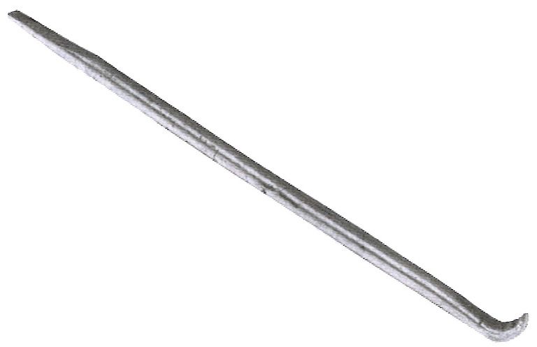
For additional copies of this Rim/Wheel Safety & Service Manual
               and other information call or write:

                    Accuride Corporation
                    Literature Distribution
                       7140 Office Circle
                     Evansville, IN 47715
                        (812) 962-5000
                        (800) 626-7096

                  Accuride Field Engineering
                    (800) 869-2275 Ext. 2

                   www.AccurideCorp.com
TABLE OF CONTENTS
Section Page
I Safety Warning 2 I
II Training of Employees Who Service Truck Tires and Rims/Wheels 3 II
III Safety Procedures for Servicing Truck Tires and Rims/Wheels 4 III
IV Correct Names of Rim/Wheel Components and Attaching Parts 12 IV
V Important Equipment for Tire and Rim/Wheel Servicing 16 V
VI Recommended Tools for Servicing Truck Tires and Rims/Wheels 18 VI
VII How to Identify Damaged Rims/Wheels 20 VII
VIII How to Properly Maintain Rim/Wheel Components 23 VIII
IX Chart for Properly Matching Side and Lock Rings to Rims/Wheels 24 IX
X Chart for Properly Matching Truck Tires to Rims/Wheels 25 X
XI Tire Mounting and Demounting Instructions XI
5° Commander®, VE 5°, and Convertible CR3 and FL3 3-Piece Rims/Wheels 26
LW, LB, MS, and Convertible CR2 and FL2 2-Piece Rims/Wheels 27
15° Drop-Center Tubeless Rims/Wheels and Accuride Tubeless Aluminum Wheels 28
5° Drop-Center Wheels: 16x6K and 16x7K 30
Duplex® 15° Drop-Center Tubeless Rims/Wheels 32
Machine Mounting for Light Truck Tires (Single Piece Wheels) 34
Machine Mounting for Heavy Truck Tires (Single Piece Rims/Wheels), Including Aluminum Wheels 37
XII Procedures for Inspecting and Installing Accuride Rims/Wheels on Vehicles XII
Heavy Truck Steel Disc Wheels 38
Heavy Truck Aluminum Wheels 44
Duplex® Rims/Wheels for Wide Base Tires 48
Light and Medium Truck Steel Disc Wheels 50
Demountable Rims 53
XIII Procedures for Installing Wheel-Guard® Separator Plates on Vehicles 56 XIII
XIV Finish Coatings 57 XIV
XV OSHA Standard 29 CFR Part 1910.177 (Servicing Multi-Piece and Single Piece Rim/Wheels) 58 XV
XVI Limited Warranty 62 XVI
XVII Employee Safety Record Inside Back Cover XVIISECTION I: SAFETY WARNING
Accuride wants you to use all rim/wheel and tire components with safety and satisfaction.
SAFETY WARNING: An exploding tire or rim part can injure or kill. The air pressure in an inflated truck tire is
explosive enough to burst tire/rim components apart with great force. This is true of both single piece and
multi-piece assemblies. To help avoid accidents, follow all instructions below. Read the Safety Procedures in
Section III, and follow all guidelines in this manual.
Improper handling and assembly of truck tires and rims/wheels can cause serious or fatal accidents. Components can explode at any time
when proper procedures have not been followed, including during:
removal from vehicle
demounting
inflation
later handling or while on the vehicle
Follow these guidelines:
Do not service any tires or rims/wheels without proper training. (Refer to OSHA standard in the back of this manual.)
Use recommended tools and safety equipment.
Use clean, matching components in good condition. Scrap any worn-out, damaged, excessively rusted, or
corroded parts.
Learn and follow safe operating procedures. Every time.
Assemble components according to recommended procedures. Don’t take shortcuts.
If you aren’t sure about a procedure or can’t find size markings on the components, don’t mount and inflate the tire.
Get expert help.
Prevent injuries and costly damage. Read, understand, and follow this manual.
2SECTION II: TRAINING OF EMPLOYEES WHO SERVICE
TRUCK TIRES AND RIMS/WHEELS
The following Accuride Safety and Service information is available free of charge:
I
Rim and Ring Matching Chart for Accuride Rim/Wheel Parts
Hub Piloted/Stud Piloted Wheel Mounting System Identification Chart II
Wheel Out of Service Guidelines Wall Chart
ACC8.0011 Accuride Service Videos (DVD)
Best practices in torque and clamping force bulletin
Accuride Wheels also has Rim/Wheel information available free of charge in French and Spanish.
See inside front cover for ordering instructions.
3SECTION III: SAFETY PROCEDURES FOR SERVICING
TRUCK TIRES AND RIMS/WHEELS
The following guidelines are very important safety procedures. If you service truck tires and rims/wheels, READ,
UNDERSTAND, and FOLLOW these safety procedures. Improper service procedures can lead to serious, even fatal,
accidents for you or others.
Note: For mounting and demounting steps for specific rim/wheel types see Section XI, beginning on page 26, in this manual.
1. DEFLATE TIRES BEFORE SERVICING
Always deflate the tire completely before removing from vehicle (deflate both tires of a dual assembly). Unseen
damage could cause the assembly to explode during removal if the tire is removed while still inflated.
Remove valve core to ensure the tire is deflated.
Run a piece of heavy wire through the valve stem to make sure stem is not plugged.
Run a wire through the valve stem.
WARNING: Do not add air to tire and rim assemblies that have been operated in a seriously underinflated or
flat condition. Adding air to such an assembly can cause it to separate explosively. The tire can explode
causing serious or fatal injury.
Always deflate, remove from the vehicle, disassemble, and inspect a tire and rim assembly that has been operated in
a run-flat or underinflated condition (80% or less of recommended pressure). This is required by OSHA Standard
1910.177.
In dual assemblies use an air gauge and check the pressure in both tires. You may not be able to tell if only one tire
is flat or underinflated, because the weight of the vehicle is carried by the other tire.
“Eyeballing” the tire or “thumping” it does not tell you the pressure reading. Always use an air gauge to measure
tire pressure.
Don’t stand in front of a tire/rim during deflation. In case of an explosive disassembly, you want to be out of the
trajectory (danger zone).
4III
2. INSPECT PARTS BEFORE ASSEMBLY
USE ONLY PROPERLY MATCHING PARTS: Rims and rings must match by size and type (See page 24 for more details). Be
sure all parts of your assembly are correctly matched. Remember: Just because parts arrive together doesn’t mean they
belong together.
WARNING: Mismatched tire and rim components may explode and cause serious injury or death.
Size and type stamping appears on every Accuride rim or side/lock ring. The stamping is generally found on the rim
near the valve slot. If you cannot read the size or type stampings on any part, do not use the parts. Such parts
should be destroyed and discarded.
Rim components must not be interchanged
except as provided for in the Multi-Piece
Rim Matching Chart. See page 3 to get free
copies of these charts.
Be sure your tire size is approved for your
rim. Rims/Wheels can accommodate tires of
varying widths. Check the chart on page 25.
Be sure the diameter shown on the tire
exactly matches the diameter stamped on
the rim/wheel. Don’t rely on eyeball
estimates. Even a small difference could
cause an accident.
5SECTION III: SAFETY PROCEDURES FOR SERVICING
TRUCK TIRES AND RIMS/WHEELS (continued)
WARNING: Mounting a smaller diameter tire on a larger diameter rim/wheel (for example, a 16-inch tire on a 16.5-
inch rim/wheel) can result in failure of the tire bead during mounting or airing. Mounting a larger diameter tire on a
smaller diameter rim can result in unseating of the tire bead during operation. The tire may explode, striking a worker
or bystander with deadly force. Check tire and rim/wheel diameter before starting to mount the assembly.
BE SURE PARTS ARE IN GOOD SHAPE. Examine parts before assembling.
It takes only a few moments to inspect the rim and side/lock rings for problems. Those few moments could save your life.
Do not use damaged, worn out, or cracked parts. A leak in a tubeless assembly may be caused by a cracked rim.
Do not try to repair cracked rims. Do not put a tube in a tubeless assembly to correct a leak. Destroy any cracked
rim; it could cause an accident. For more information, see pages 20 through 22.
Check all metal surfaces for rust, corrosion, cracks, bent flanges, sprung side/lock rings, and deep tool marks on
rings or in gutter areas. The illustrations below show some of these conditions. For more information, see pages 20
through 22.
Erosion and chipping of bead seat of Sprung side ring Cracks through continuous side ring Cracks in the rim base, in the back
lock ring spreading laterally through the entire flange and gutter areas. Deep tool
section. marks on flange and gutter.
6III
Out of flat rings. Out of round rims. Cracks in rim base.
If you find parts with these problems, destroy them. There is no way to repair them. See pages 20 through 22 for more on
these problems and what to do about them.
For tubeless rims: inspect the valve stem to ensure that it is in good condition, is not cracked or bent irregularly, and
is capable of handling proper air pressure. Replace the valve stem as necessary.
3. REPLACE DAMAGED PARTS
WARNING: Use of damaged parts is very dangerous. These parts can fail during inflation, later handling, or
while on the vehicle. You or someone else could receive serious or fatal injuries.
Replace the part if there is any loss of contour or metal thickness. Loss of contour means a wearing away of the
metal mating surfaces of the rim base or side/lock rings.
Destroy and discard any rim bases and side/lock rings which are deformed or pitted from corrosion, broken, or
cracked.
Never rework, weld, braze, or otherwise heat any cracked, broken, or damaged rim/wheel components. Repaired
rim components may fail during inflation or later vehicle use.
Never weld on a rim/wheel component any time, but especially while a tire is mounted. Heat from the welding torch
causes explosive gases to be released from the rubber tire, possibly causing an explosion.
If you suspect damage in any rim/wheel component, replace the part. You’ll be giving better service to your customer and you will be
protecting yourself from accidents.
4. PREPARE PARTS BEFORE ASSEMBLING
WARNING: Dirt and rust can prevent rim components from seating properly or cause a bead hang-up (tire bead
not seating properly). Assembling such components can lead to explosive separation, resulting in serious or
fatal injury.
Remove all rust, corrosion, dirt, and other foreign material from all metal surfaces. Take particular care in the rim gutter and
bead seat areas. Also, check the mating surfaces of side/lock rings in multi-piece assemblies. For more details about proper
rim/wheel maintenance, see page 23.
PAINT RIM WITH FAST-DRYING PRIMER
A good way to prevent dangerous rust build-up is painting the rim with a fast-drying primer. See page 23 for this maintenance procedure.
Always allow paint to dry before assembling components.
7SECTION III: SAFETY PROCEDURES FOR SERVICING
TRUCK TIRES AND RIMS/WHEELS (continued)
LUBRICATE COMPONENTS BEFORE ASSEMBLY
Use only lubricants recommended by rim and tire makers, such as vegetable oil and animal soap solutions. If a lubricant is water based,
it should contain a rust inhibitor. When dry, the lubricant should not remain slippery. Do not use petroleum, silicon, or solvent-based
lubricants as these may damage the tire rubber or cause rust buildup or tire-to-rim slippage.
Apply an approved tire lubricant to rim bead seat area, tire beads, tire flap, and other rim to tire contact surfaces just before mounting tire.
See Section XI, beginning on page 26, for assembly details.
WARNING: Failure to follow proper inflation procedures can expose you or bystanders to an explosion
resulting in serious injury or death.
5. PROTECT YOURSELF DURING INFLATION
You can protect yourself and bystanders during inflation by always
observing the following safety procedures. If you cut corners on
safety procedures you may cause a serious or fatal accident.
Always inflate in a safety cage or other OSHA
approved restraining device.
Always use a clip-on air chuck and remote in-line
valve and gauge.
Always stand back. Keep yourself and others
away from and out of the trajectory of the inflating
assembly. Don’t lean or put any part of your body
on the restraining device. The air blast alone, or
Safety Cage movement of the restraining device, could cause
injury if an explosion occurs.
If tire beads are difficult to seal, use an approved device such as an
inflation ring to seat the tire. Tire bead seating equipment like this
inflation ring (shown below) is available to help seat beads of
tubeless tires.
In-line Valve and Gauge
Clip-on Air Chuck Inflation Ring
8WARNING: Never pour or spray any flammable substance (such as ethyl ether or gasoline) into or onto a tire and ignite it to
seat the beads. This practice is very dangerous and can cause a severe explosion or undetected damage to the tire or rim,
leading to serious or fatal injury. Never put any flammable substance into or on a tire or rim/wheel for any
purpose whatsoever.
Always inflate in a safety cage. However, when a tire is being partially inflated (without restraining device) to round
out the tube or seat the side/lock ring, do not inflate to more than 3 psi. Further inflation could result in explosive
separation.
Never inflate to more than 40 psi to seat tire beads. More inflation can cause a tire explosion. If tire beads do not
seat when inflated to 40 psi, deflate assembly, re-inspect the components, properly assemble, and follow proper
inflation procedures to re-inflate. III
After the tire is fully inflated, inspect the tire, rim, and rings for proper seating before removing assembled unit from
the restraining device.
TWO-PIECE RIMS
Correct Incorrect Incorrect
The components in a correctly An incorrectly assembled or An incorrectly assembled or
assembled two-piece rim damaged two-piece rim could damaged two-piece rim could
fit snugly and are locked have a large gap in side ring. have components not firmly
together. Components are not firmly locked in place.
locked in place.
THREE-PIECE RIMS
Correct Incorrect Incorrect
A three-piece rim that is An incorrectly assembled or An incorrectly assembled or
correctly assembled has firmly damaged three-piece rim could damaged three-piece rim could
fitted components that are have a large gap in the lock ring. have components not firmly
locked together. The components are not firmly locked in place
locked in place.
Never try to correct the seating of the side/lock rings by hammering, striking, or forcing the parts during servicing,
inflation, or after inflation. The components could separate explosively.
If the assembled unit is not fully seated, release the air by using your remote in-line valve that both inflates and
deflates. Then remove the valve core to make sure the tire is fully deflated, and remount.
Tires on vehicles with more than 80% of the recommended air pressure can be inflated on the vehicle. For safety,
use an in-line valve and gauge for inflation, stand clear, and keep others out of the trajectory (danger zone).
Remember: Tire/rim assemblies operated in a run-flat or underinflated condition (80% or less of recommended
pressure) can explode if you try to reinflate them. Deflate, remove from vehicle, and disassemble. Then check the
mating surfaces of parts. If they are damaged, scrap them.
9SECTION III: SAFETY PROCEDURES FOR SERVICING
TRUCK TIRES AND RIMS/WHEELS (continued)
6. PROTECT YOURSELF AFTER INFLATION
WARNING: If proper servicing, maintenance, or assembly procedures have not been followed, the tire/
wheel assembly may explode at any time, resulting in serious or fatal injuries to you or others.
u Whenever handling inflated truck tires and wheels, stay out of the trajectory (danger zone). Warn anyone near the
trajectory, too. In the performance of certain servicing procedures, such as installing or removing a rim/wheel, it may
be necessary to be within the trajectory. Extreme care should be followed.
TRAJECTORY
TRAJECTORY
Study the diagrams above. Learn the trajectories and stay clear of them.
Note that under some circumstances the trajectory may take a different path from the one you expect.
LOADING
Each tire, wheel, and axle has its own maximum rating. Do not load and inflate the tire/wheel/axle system beyond the
capacity of the lowest rated component. Overloading causes tire failure and injury accidents.
If a tire has less capacity (load/inflation) than the rim/wheel or axle (GAWR) it is used with, use the capacity limits of
the tire, not the wheel or axle. The GAWR can be found on the vehicle placard.
If a rim/wheel has less capacity (load/inflation) than the tire or axle (GAWR) it is used with, use the capacity limits of
the rim/wheel, not of the tire or axle. The GAWR can be found on the vehicle placard.
Rims and wheels produced by Accuride are designed and tested to meet the requirements of specific tires or vehicles. Some high load
capacity/high inflation tires are being used in North America. These ratings may exceed the rated capacity for all rims and wheels produced
by Accuride. These high load capacity/high inflation tires cannot be used on existing rims and wheels unless you keep load and tire inflation
pressure below the maximum load rating and inflation rating of the rims or wheels. You can find further information in the Accuride Wheels
Product Catalog. Read and understand this information before using these products on vehicles.
107. INSTALL WHEEL ON VEHICLE PROPERLY
WARNING: Improperly installed wheels can fail and lead to an accident. Serious injury or death may result.
When you mount the rim/wheel on the vehicle, be sure to pay attention to the following:
Proper size of nut and stud (and clamp where required).
Proper installation of spacer band on dual demountable rim assemblies.
Correct nut tightening sequence.
Correct torque (tightening expressed in foot-pounds) of the nuts. See the section on Procedures for Inspecting and
Installing Accuride Rims/Wheels on Vehicles, pages 38 through 55.
For installation procedures for specific types of Accuride wheels and rims, see the sections listed below: III
Heavy Truck Steel Disc Wheels, see pages 38 through 43.
Heavy Truck Aluminum Wheels, see pages 44 through 47.
Duplex® Rims/Wheels for Wide Base Tires, see pages 48 through 49.
Light and Medium Truck Steel Disc Wheels, see pages 50 through 52.
Demountable Rims, see pages 53 through 55.
8. TAKE CARE DURING VEHICLE OPERATION
Inspect rims and wheels for damage during tire checks and at periodic maintenance intervals. Remove and replace damaged or worn parts.
WARNING: Improperly maintained rims and wheels can fail and lead to an accident. Serious injury or death
may result.
Do not run vehicle on one tire of a dual assembly. When there is loss of air in a dual tire, the carrying capability is
reduced and the load must be carried by the other tire and rim. See that both tires are inflated to equal
recommended pressures before further operation.
Tire/rim assemblies operated in a run-flat or underinflated condition (80% or less of recommended pressure) can be
worn, dislodged, or damaged. If you add air to this assembly, it may explode and cause serious injury or death.
Instead, fully deflate, remove from vehicle, and disassemble. After disassembly, check the mating surfaces of parts.
If the parts are sound, reassemble and inflate in a safety cage. If parts are damaged or worn, scrap them.
Recheck the torque level of nuts between the first 50 and 100 miles of operation and as part of a vehicle’s ongoing
scheduled maintenance or at 10,000 mile intervals, whichever comes first. Retighten, if necessary, to the
recommended torque using the proper sequence.
11SECTION IV: CORRECT NAMES OF RIM/WHEEL
COMPONENTS AND ATTACHING PARTS
There is confusion over the terms “wheel” and “rim” in the industry. Please read the following definitions so you will
understand the terms appearing in this manual. Remember, a rim is not a wheel and a wheel is not a rim. Likewise, there is
an important difference between a side ring and a lock ring.
RIM
The rim supports the tire. There are two types of rims: a single piece rim (tubeless—some 16 inch single piece rims are either tubeless or
tube-type) and a multi-piece rim (tube-type). A SINGLE PIECE RIM is a continuous one-piece assembly. A MULTI-PIECE RIM is an assembly
consisting of a base and either a side ring or a side and lock ring depending on the type. A DEMOUNTABLE RIM does not have a center disc
and is clamped onto a cast spoke wheel.
Tubeless Demountable Rim (single piece) Tube-Type Demountable Rim Assembly (multi-piece)
shown in cross section
DISC WHEELS
Tubeless Disc Wheel Tube-Type Disc Wheel Assembly
A combination of a rim and a disc permanently attached to the rim and attached to the hub by studs and nuts.
12CAST SPOKE WHEEL
As the name implies, it consists of a casting which includes the hub and either 3, 5, or 6 spokes. This is an axle component that demountable
rims are attached to with clamps. There are designs with different numbers of clamps with various shapes. Each cast spoke wheel requires
clamps designed for the cast spoke wheel. A spacer band is used with duals on rear cast spoke wheels. Typical designs are shown.
IV
5 Spoke 5 Spoke
Cast spoke wheel with brake drum and clamps (for rear axles) Cast spoke wheel with clamps,
without brake drum (for front axles)
SPACER BAND
Used on rear cast spoke wheels, the spacer band holds the two rims apart and provides proper dual spacing for the tires.
13SECTION IV: CORRECT NAMES OF RIM/WHEEL
COMPONENTS AND ATTACHING PARTS (continued)
SPLIT SIDE RING
In two-piece assemblies, the side ring retains the tire on one
side of the rim. The fixed flange supports the other side. The
split side ring is designed so that it acts as a self-contained lock
ring as well as a flange.
Split Side Ring
FLANGE OR CONTINUOUS SIDE RING
In three-piece assemblies, the flange or continuous side ring
supports the tire on one side of the rim. The continuous side
ring is, in turn, held in place by a separate split lock ring.
Flange or
Continuous Side Ring
SPLIT LOCK RING
All lock rings are split. In three-piece assemblies, the lock ring
is designed to hold the continuous side ring on the rim.
Split Lock Ring
14STUDS AND NUTS FOR DISC WHEELS
Typical examples of studs, nuts and clamping plates used with disc wheels are illustrated in this section. A typical stud (Fig. 1) used with
in-board brake drums has a 3/4” thread on both ends, a shoulder with two flats, and is longer from the shoulder on the one end with an
unthreaded section. The flat surfaces of the shoulder fit into the recessed outer surface of the hub to keep the stud from turning. The
smooth portion is long enough to fit through the hub and the brake drum, and is then held in place by a back or jam nut (Fig. 2). For
outboard brake drums a serrated stud with threads on one side is typically used (Fig. 3).
Fig. 3
Fig. 2 Fig. 10
Fig. 4
Fig. 1
IV
Fig. 7 Fig. 9
Fig. 5 Fig. 6 Fig. 11
Fig. 8
On front stud mount wheels, an outer cap nut (Fig. 4) or (Fig. 6) is used. On stud mount rear dual wheel applications, the inner wheel is
held in place by an inner cap nut (Fig. 5) and the outer wheel by an outer cap nut (Fig. 6).
For hub mount wheels which pilot from the center hole, flange nuts are used on both the front and rear wheels. One-piece flanged cap nuts
(Fig. 7) are used on light truck and medium truck applications. Heavy trucks and buses and some light trucks use a two-piece flange nut or
swiveling lug nut (Fig. 8) when hub mount wheels are used. Some light trucks use a clamping plate (Fig. 9) and 90° cone nuts (Fig. 10) for
both the front and rear wheel. Light trucks which use single wheels on the front and rear axle require 90° cone nuts or 60° cone nuts (Fig.
11), depending on the truck manufacturer.
RIM CLAMPS, STUDS AND NUTS FOR DEMOUNTABLE RIMS
The stud for cast spoke wheels (Fig. 12), threaded on both ends, is installed in a threaded hole at the end of a spoke. The front clamp (Fig.
13) and a rear clamp (Fig. 14) hold the demountable rim in position with studs and nuts (Fig. 15). A clamp for a three-spoke wheel with two
stud holes is shown in (Fig. 16).
Fig. 15
Fig. 16
Fig. 12
Fig. 13
Fig. 14
15SECTION V: IMPORTANT EQUIPMENT FOR
TIRE AND RIM/WHEEL SERVICING
Using proper tools and safety equipment can help prevent personal injuries and costly damage. Remember, an inflated truck tire contains
explosive energy. This can cause the tire/rim components to burst apart with great force. Protect yourself. Use the servicing equipment
recommended below.
1. Always inflate in a safety cage using a clip-on
air chuck or use an OSHA-approved restraining
device with a clip-on air chuck.
This is a safeguard against injury resulting from
assembly errors.
A safety cage is your best protection if there is an
explosion during inflation.
Safety Cage
2. Always use a clip-on air chuck with an in-line valve and gauge with sufficient length of hose to stand clear.
WARNING: Facing the side/lock rings against a wall or other permanent structure during inflation is not safe. If the assembly
explodes, you can be struck by flying components. Fully restrain the tire and rim/wheel during inflation.
Clip-on Air Chuck In-line Valve and Gauge
A clip-on air chuck allows you to keep your hands, arms, and body clear during inflation.
An in-line valve allows you to control the air flow while standing away from the assembly.
An in-line gauge allows you to monitor the air pressure going into the tire during inflation.
WARNING: Inflating a truck tire with a hand-held air chuck is dangerous. You have to put your hand
inside the safety cage or the restraining device. You can’t stand clear. You can be seriously injured.
163. Display and use current demounting and mounting
procedure chart and matching chart.
A demounting and mounting procedure chart
shows you the proper procedure to follow when
servicing truck tires and rims/wheels.
A matching chart shows you which components you
can put together safely. You need to properly match
the rim and the side and lock rings when servicing
multi-piece rims/wheels. Remember, you also need
to match the rim/wheel to the tire.
Typical examples of these charts are:
“Demounting and Mounting Procedures for
Truck/Bus Tires”*
“Multi-Piece Rim Matching Chart”*
* These reference materials are available for download from OSHA at: http://www.osha.gov/pls/publications
Reference numbers are: V
Demounting and Mounting Procedures for Tubeless Truck and Bus Tires Chart - Tire Chart (OSHA 3401)
Demounting and Mounting Procedures for Tube-type Truck and Bus Tire Chart - Tire Chart (OSHA 3402)
Multi-Piece Rim Matching Chart - Tire Chart (OSHA 3403)
Servicing Multi-Piece and Single-Piece Rim Wheels 29 CFR 1910.177 Manual - Tire Chart (OSHA 3421)
The following Accuride Safety and Service information is also available free of charge:
Rim and Ring Matching Chart for Accuride
Rim/Wheel Parts
Wheel Out of Service Guidelines Wall Chart
Hub Piloted/Stud Piloted Wheel Mounting System
Identification Chart
Accuride Service Videos (USB, YouTube, Accuridecorp.com)
Accuride also has Rim/Wheel information available free of charge in Spanish.
4. Maintain and use current rim/wheel manuals.
A current rim/wheel manual should be available in the service area. This manual should contain instructions for the
type of rims/wheels you service.
Rim/wheel manuals are available from rim/wheel manufacturers or your local rim/wheel distributor.
5. Use proper tools.
Use only the tools recommended by the manufacturer for servicing the specific tire and rim.
Pages 18 and 19 of this manual show the proper tools and pages 26 through 37 show the mounting and
demounting instructions for servicing truck tires and rims/wheels.
17SECTION VI: RECOMMENDED TOOLS FOR SERVICING
TRUCK TIRES AND RIMS/WHEELS
Use only recommended tools for mounting and demounting truck tires and servicing rims/wheels. The use of the proper tools allows the
safe mounting and demounting of tires and rims/wheels and prevents damage to the rim. The use of improper tools can cause damage to
the components.
Do not strike components of a rim/wheel assembly with a hammer or similar instrument in an attempt to seat the rings
into the gutter. This can cause damage to the rim and rings which could lead to component failure. Rubber,
leather-faced, or plastic rim mallets may be used to tap rings into the gutter. Do not use lead, steel, or bronze rim
mallets which can chip or shatter, causing injury.
The duck bill hammer should not be used to strike the bead/rim area. This could cause damage to the rim or tire.
Duck bill hammers which are a combination rim mallet and driving iron should only be used in the following manner:
The wedge end should be placed between the tire and rim flange and the opposite side struck by another rim mallet
to separate the tire bead from the rim flange.
Bead seal breaking machines may be used with tires/rims and may make tire demounting easier.
The following tools are recommended for use with Accuride rims/wheels. The specific tools for each rim type are shown in the mounting
and demounting instruction pages for that rim type.
1. Rim Tools
Tubeless Tire Iron Duplex Extension Tool
Duplex “C” Tool Lock Ring Tool
182. Bead Seal Breaking Tools
Swan Neck Bead Tool
Driving Iron
VI
Bead Seal Breaking Machine
3. Rim Mallet 4. Self-Locking Pliers
5. Tire Mounting Machine 6. Lubricant and Brush
19SECTION VII: HOW TO IDENTIFY DAMAGED RIMS/WHEELS
Rim/wheel components can become damaged. Check all metal surfaces for rust or corrosion buildup, cracks in metal, bent flanges and
side rings, and deep rim tool marks on rings or in gutter areas. Watch for the problems illustrated on the following 3 pages and take the
corrective actions to prevent further problems. Remember, it is dangerous to assemble cracked, bent, severely corroded, or sprung rim/
wheel components. Such items should be destroyed and discarded.
RIM BASE CRACKS
RIM BASE DISTORTION MOUNTING RING PROBLEMS
20DISC WHEEL CRACKS/BOLT HOLE DISTORTION
VII
TUBELESS RIM LEAKS
21SECTION VII: HOW TO IDENTIFY DAMAGED RIMS/WHEELS
(continued)
Continuous Flange Cracks
Lateral crack through section. Causes: Overloading, over inflation, damaged mating surfaces,
bent ring, excessive corrosion-erosion, or excessive clamp torque on demountable rims.
Split Side Ring Problems
Cracked ring. Causes: Overload, over inflation, improper installation, or removal.
Sprung ring. Causes: Improper installation, or removal.
Split Lock Ring Problems
Excessive corrosion-erosion. Causes: Improper maintenance, or mounting lubricant.
Circumferential and lateral cracks. Causes: Corrosion, improper fit-up due to damaged parts,
hammer blows, dents, etc.
22SECTION VIII: HOW TO PROPERLY MAINTAIN RIM/WHEEL COMPONENTS
Thoroughly remove rust, dirt, and other foreign materials from
all surfaces. Hand or electric wire brushes or sand blasting may
be used.
Gutter of rim base should be cleared of rust and other
materials that could obstruct seating of rings.
Bead seat areas of rim should be free of rust and rubber deposits. VII
This is especially important for drop-center tubeless rims,
because the bead seat is the air-sealing element. VIII
Paint rim by brush or spray with a fast-drying metal primer.
Surfaces should be clean and dry prior to painting. Ensure that
Rings should be cleaned with wire brushes. Pay particular bare metal areas on outside or tire side of rim are covered. This
attention to seating surfaces and bead seat areas. is especially important on drop-center tubeless rims, because
warm and sometimes moist air is in constant contact with the
metal surface on the tire side of the rim.
Wheel disc mating surfaces must be kept flat. Remove any metal
projections, burrs at the stud hole chamfers and paint buildup.
23SECTION IX: CHART FOR PROPERLY MATCHING
SIDE AND LOCK RINGS TO RIMS/WHEELS
It is important to recognize that the various types and sizes of highway rims produced by their manufacturers all differ to some degree in design.
This is particularly important of removable rings, since side and lock rings of different rim types are not generally interchangeable. Some rings are
common to two types or sizes, and are identified with each size and type.
Some rings may appear to fit but they actually do not fit properly on the rim base. Serious accidents to personnel may result from the use of
mismatched rings. IF YOU CAN’T FIND THE STAMPING OR READ THE STAMPING ON MULTI-PIECE RIMS, WHEELS OR RINGS, DON’T USE THE PARTS.
THEY SHOULD BE DESTROYED AND DISCARDED.
The chart below shows the only components which are interchangeable with Accuride parts.
Rim and Ring Matching Chart for Accuride Rim/Wheel Parts
WARNING: Improperly assembled parts could result in personal injury or death. Use only rings that are stamped
with the same size and type as the rim base. All components are stamped with size and type information Do not
use parts you can’t identify.
Instructions On How To Use Charts
The following charts list combinations of components that are approved for use together. The stamped marking on the rim base is noted in the left
hand column. Rim bases with a particular stamping should be matched only with the side rings (2-piece assemblies) or side and lock rings (3-piece
assemblies) listed directly to the right.
For example: A 20x7.0 CR rim base can be used only with a 2-piece 20x6.5-7.0 CR or R6520CR side ring or a 3-piece 20x6.5-7.0 CR or LR20x6.5-7.0 CR
or LR6520CR lock ring and 20x7.0 5°-FL-CR or F20x7.0 CR or F7020CR side ring.
The charts below note the only components which are interchangeable with Accuride parts. For more comprehensive information, including
components made by other manufacturers, consult the OSHA “Multi-Piece Rim Matching Chart”.
2-Piece FL-CR Type Convertible Rims 3-Piece FL-CR Type Convertible Rims
Rim Base Markings Side Ring Markings Rim Base Markings Lock Ring Markings Side Ring Markings
20x6.5 CR or B6520CR 20x6.5-7.0 CR or R20x6.5-7.0 CR or 20x6.5 CR or 20x6.5-7.0 CR or 20x6.5 5°-FL-CR or
R6520CR B6520CR LR20x6.5-7.0 CR or F20x6.5-CR or
20x7.0 CR or B7020CR 20x6.5-7.0 CR or R6520CR LR6520CR F6520CR
20x7.5 FL or B7520FL 20x7.5 FL or R20x7.5 FL or R7520FL 20x7.0 CR or 20x6.5-7.0 CR or 20x7.0 5°-FL-CR or
B7020CR LR20x6.5-7.0 CR or F20x7.0CR or
22x7.5 FL or B7522FL 22x7.5 FL or R22x7.5 FL or R7522FL LR6520CR F7020CR
2-Piece LB - LW Type Rims 20x7.5 FL or 20x7.5 FL or 20x7.5-8.0 5°-7.5FL or
Rim Base Markings Side Ring Markings B7520FL LR7520x7.5 FL or 20x7.5 5°-FL or
20x6.5 LB or B6520LB 20x6.5-7.0 LBLW or LR7520FL F20x7.5FL or
R20x6.5-7.0 LBLW or R6520LW F7520FL
20x7.0 LB or B7020LB 20x6.5-7.0 LBLW or 22x7.5 FL or 22x7.5 FL or 22x7.5-8.0 5°-7.5FL or
R20x6.5-7.0 LBLW or R6520LW B7522FL LR22x7.5 FL or 22x7.5 5°-FL or
20x7.5 LB or B7520LB or 20x7.5-8.0 LBLW or LR7522FL F22x7.5FL or
G20750B R20x7.5-8.0-9.0 LBLW or F7522FL
R8020LW 3-Piece 5° - VE 5° Type Radial Commander® Rims
22x7.5 LB or B7522LW or 22x7.5-8.0 LBLW or Rim Base Markings Lock Ring Markings Side Ring Markings
G22750B R22x7.5-8.0-9.0 LBLW or 20x7.0 5° 20x7.0-7.5-8.0 5° 20x7.0 5°-FL-CR or
R8022LW F7020FL
20x7.5 LW or 20x7.50LW or 20x7.5-8.0 LBLW or 20x7.5 5° or 20x7.0-7.5-8.0 5° 20x7.5-8.0 5°-7.5FL or
B7520LW or G20750B 20x7.5-8.0-9.0 LBLW or R8020LW 20x7.50 5° or 20x7.5 5°-FL or
F20750B F7520FL
20x8.0 LW or 20x8.00 LW or 20x7.5-8.0 LBLW or
22x7.5 5° or 22x7.0-7.5-8.0 5° 22x7.5-8.0 5°-7.5FL or
B8020LW or G20800B R20x7.5-8.0-9.0 LBLW or R8020LW
22x7.50 5° or 22x7.5 5°-FL or
2-Piece MS Type Rims
F22750B F7522FL
Rim Base Markings Side Ring Markings 20x8.0 5° or 20x7.0-7.5-8.0 5° 20x8.0 5° or
20x7.5 MS 20x7.5 MS 20x8.00 5° or 20x7.5-8.0 5°-7.5FL
F20800B
22x8.0 5° or 22x7.0-7.5-8.0 5° 22x8.0 5° or
22x8.00 5° or 22x7.5-8.0 5°-7.5FL
F22800B
For typical rim stamping location see page 5. 24x8.0 5° 24x8.0 5° 24x8.0 5° or
24x7.5-8.0 5°
20x8.5 5° 20x8.5 5° 20x8.5 5°
24x8.5 5° 24x8.5 5° 24x8.5 5°
20x10.00VE 5° 20x8.5 5°/10.00VE 5° 20x8.5 5°/10.00VE 5°
24 x 8.5 – 5° 24 x 8.5 – 5° 24 x 8.5 – 5°
8.5 – 24 8.5 – 24 8.5 – 24
24SECTION X: CHART FOR PROPERLY MATCHING
TRUCK TIRES TO RIMS/WHEELS
Information obtained from The 2018 Tire and Rim Association Yearbook.
Tire Size(1) Approved Rim Contours(2) Tire Size(1) Approved Rim Contours(2)
LIGHT TRUCKS MEDIUM AND HEAVY DUTY TRUCKS
6.50 16LT 4½K, 4.50E, 5K, 6K, 6L 11.00 24 7.5, 8.0, 8.5, 8.50VM
7.50 16LT 5.50F (SDC), 6K, 6L, 6½L, 7L 12.00 24 8.0, 8.5, 8.50VM, 9.0
LT225/75 16 6J, 6½J, 7K 8 19.5 5.25, 6.00, 6.00RW, 6.75, 6.75RW
LT245/75 16 6½J, 7J, 7½J, 8J 225/70R 19.5 6.00, 6.00RW, 6.75, 6.75RW
LT265/75 16 7J, 7½J, 8J 245/70R 19.5 6.75, 6.75RW, 7.50, 7.50RW
LT285/75 16 7½J, 8J, 8½J, 9J 265/70R 19.5 7.50, 7.50RW, 8.25, 8.25RW
LT215/85 16 5½J, 6J, 6½J, 7J 305/70R 19.5 8.25, 8.25RW, 9.00
LT235/80 17 6J, 6½J, 7J, 7½J 9 22.5 6.00, 6.75, 7.50
LT235/85 16 6J, 6½J, 7J, 7½J 10 22.5 6.75, 7.50, 8.25
LT255/85 16 6½J, 7J, 7½J, 8J 235/80R 22.5 6.75, 7.50
LT235/70 16 6J, 6½J, 7J, 7½J 245/75R 22.5 6.75, 7.50
LT255/70 16 6½J, 7J, 7½J, 8J 255/70R 22.5 6.75, 7.50, 8.25
LT265/70 17 7J, 7½J, 8J, 8½J 265/75R 22.5 7.50, 8.25
LT275/70 16 7J, 7½J, 8J, 8½J 11 22.5 7.50, 8.25
8.75 16.5 6.00, 6.75 275/80R 22.5 7.50, 8.25, 9.00
9.50 16.5 6.75, 8.25 295/75R 22.5 8.25, 9.00
LOW PLATFORM TRAILERS 305/75R 22.5 8.25, 9.00
9R17.5HC 6.75HC, 6.75 12 22.5 8.25, 9.00 IX
215/75R 17.5HC 6.00HC, 6.75HC 315/80R22.5 8.25, 9.00, 9.75
10R17.5HC 6.75HC, 7.50HC, 6.75, 7.50 11 24.5 7.50, 8.25 X
275/80R 24.5 7.50, 8.25, 9.00
(1) A denotes both radial and bias tires. An R indicates radial tires only.
(2) SDC denotes semi-drop center rims. 12 24.5 8.25, 9.00
Note: For tire sizes not shown, consult the Tire Manufacturer for approved rim 285/75R 24.5 7.50, 8.25, 9.00
contours. WIDE BASE (DUPLEX®)
15 22.5 11.75, 12.25
385/65R 22.5 11.75, 12.25
16.5 22.5 12.25, 13.00
425/65R 22.5 12.25, 13.00, 14.00
445/50R 22.5 14.00, 15.00
445/65R 22.5 13.00, 14.00
455/55R 22.5 14.00, 15.00
18 22.5 13.00, 14.00
WARNING: Failure to properly match tire and rim/wheel sizes is dangerous. Mounting a smaller diameter tire on a larger diameter rim/wheel
(for example, mounting a 16 inch tire on a 16.5 inch rim/wheel) can result in breaking the tire bead during mounting or airing. The tire may
then explode during inflation. The explosion can hurl the tire and wheel into the air striking you or a bystander. Be sure the diameter shown on
the tire exactly matches the diameter stamped on the rim/wheel.
25SECTION XI: TIRE MOUNTING AND DEMOUNTING INSTRUCTIONS
WARNING: Before working on any tire/rim assembly, be sure you are trained and thoroughly familiar with the
safety guidelines in Section III of this manual. Improper servicing of tire/rim assemblies can lead to serious, even
fatal, accidents for you or others. Follow recommended mounting/demounting procedures carefully.
5° COMMANDER®, VE 5°, AND CONVERTIBLE CR3 AND FL3 3-PIECE RIMS/WHEELS Continuous Side Ring
Tools Required:
1 Rim mallet Lock Ring
1 Ring tool
2 Swan necked bead tools Rim Base Gutter
Lubricant & brush
See Section VI, page 18, for recommended tools.
DEMOUNTING
1.Before loosening any nuts securing tire and rim assembly to the vehicle, remove valve
core and deflate tire completely. If working on duals, deflate both tires completely.
Run wire through valve stem to ensure deflation.
Remove tire and rim assembly from truck and place on floor, side ring up.
Insert hooked end of swan necked bead tool between side ring and side wall of
tire. Apply downward pressure on rim tools to pry bead loose from side ring.
Continue prying progressively around tire until bead is completely free from side ring.
2. To remove lock ring push the side ring and tire bead down.
Insert tapered end of rim tool into notch near split in lock ring.
Push rim tool downward and pry lock ring outward to remove from gutter of rim base.
Use hooked end of rim tool to complete removal of lock ring, progressively
working around tire. Lift off side ring.
Turn assembly over. Unseat remaining tire bead from rim. Lift rim from tire.
MOUNTING
1. Inspect the tire and rim for any damage. Be sure tire size and rim size match exactly.
2. Insert tube into the tire and partially inflate to no more than 3 psi to round out tube.
Apply tire lubricant to inside and outside surfaces of both beads. Lubricate
portion of tube that appears between beads.
Insert flap and lubricate.
Lay rim flat on floor with gutter side up. Align tube valve with rim valve slot center.
Push tire onto rim. Insert valve through valve slot.
3. Place side ring on rim base. Stand on ring to position it below gutter in rim base.
Snap leading end (end without notch) of lock ring into gutter of rim base.
Progressively “walk” lock ring into place. Check to ensure lock ring is fully seated
in gutter.
4. Inflate to no more than 3 psi. Again check proper engagement of lock ring. If assembly is not
proper, deflate and correct. Never hammer on an inflated or partially inflated tire/rim assembly.
5. Inflate the tire.
Put tire/rim assembly in safety cage or other OSHA-approved restraining device.
Use an extension hose with an air gauge and clip-on air chuck. Stand clear of
the assembly.
Inflate tire to recommended pressure to seat beads. Check to see if beads are
properly seated.
Completely deflate tire to prevent buckling of tube.
Reinflate tire to recommended pressure.
Before removing from safety cage or restraining device - check to see that rim
component are properly seated.
26LW, LB, MS, AND CONVERTIBLE CR2 AND FL2 2-PIECE RIMS/WHEELS
Split Side Ring
Tools Required:
1 Rim mallet Gutter
1 Ring tool Rim Base
2 Swan necked bead tools
Lubricant & brush
See Section VI, page 18, for recommended tools.
DEMOUNTING
1.Before loosening any nuts securing tire and rim assembly to the vehicle, remove valve
core and deflate tire completely. If working on duals, deflate both tires completely. Run
wire through valve stem to ensure deflation.
Remove tire and rim assembly from truck and place on floor, side ring up.
Insert hooked end of swan necked bead tool between side ring and side wall of tire.
Apply downward pressure on rim tools to pry bead loose from side ring.
Continue prying progressively around tire until bead is completely free from side ring.
2. To remove side ring push the tire bead down.
Insert tapered end of rim tool into notch and pry side ring out of gutter.
Pry progressively around tire until side ring is free of the gutter.
3. Turn assembly over. Unseat remaining tire bead from rim. Lift rim from tire.
MOUNTING
1. Inspect the tire and rim for any damage. Be sure tire size and rim size match exactly.
2. Insert tube into the tire and partially inflate to no more than 3 psi to round out tube.
Apply tire lubricant to inside and outside surfaces of both beads. Lubricate portion
of tube that appears between beads.
Insert flap and lubricate.
Lay rim flat on floor with gutter side up. Align tube valve with rim valve slot.
Push tire onto rim. Insert valve through valve slot.
3. Place side ring on rim base so that ring split is opposite valve stem. XI
Place leading end (end without notch) of ring into the groove in the rim as shown.
Progressively “walk” side ring into place. Check to ensure ring is fully seated in
gutter.
4. Inflate to no more than 3 psi. Again check proper engagement of side ring. If assembly
is not proper, deflate and correct. Never hammer on an inflated or partially inflated
tire/rim assembly.
5. Inflate the tire.
Put tire/rim assembly in safety cage or other OSHA-approved restraining device.
Use an extension hose with an air gauge and clip-on air chuck. Stand clear of the
assembly.
Inflate to recommended tire pressure seat beads. Check to see if beads are
properly seated.
Completely deflate tire to prevent buckling of tube.
Reinflate tire to recommended pressure.
Before removing from safety cage or restraining device - check to see that rim
components are properly seated.
27SECTION XI: TIRE MOUNTING AND
DEMOUNTING INSTRUCTIONS (continued)
15° DROP-CENTER TUBELESS RIMS/WHEELS AND
ACCURIDE TUBELESS ALUMINUM WHEELS
Well Well
Tools Required: Flange
1 Rim mallet
1 Self-locking pliers
1 swan necked bead tool
2 Tubeless tire tools Flange
Lubricant & brush Short Side
OR of Rim
Tire changing machine STEEL DISC WHEEL ALUMINUM WHEEL
(Instructions on page 37)
Lubricant & brush
See Section VI, page 18, for recommended tools.
DEMOUNTING (By Hand)
Before loosening any nuts securing tire and rim assembly to the vehicle, remove valve core and deflate
tire completely. If working on duals, deflate both tires completely. Run wire through valve stem to
ensure deflation. Remove tire and rim assembly from truck and place on floor.
1. Loosen bead from rim:
Drive the flat end of the swan necked bead tool between tire bead and rim flange.
Straighten tool to an upright position and hammer downward on the neck to pry tire
from rim.
Repeat at about eight-inch intervals around flange until bead is free from rim.
Turn assembly over and repeat to loosen other bead.
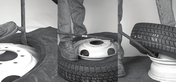
2. Lay assembly flat on floor with short side of rim up. Lubricate tire bead and rim.
Insert curved end of tubeless tire tool in tire at valve. Step on tire opposite valve to
direct first bead into the well.
Pull tool toward center of rim lifting the tire over the flange until it touches both
rim flanges.
Hold tool in position with foot. Insert and pull second tool toward center of rim.
Progressively work tools around rim until first bead is off rim.
3.Stand assembly in vertical position with valve near top. Lubricate second bead and rim.
Be sure opposite side of second bead is into well.
Insert straight end of tool between tire bead and the back rim flange, hooking the tool
over the top of the second flange.
Lean tire assembly toward tool and provide a rocking or bounding action to pry the rim
out of the assembly.
28MOUNTING (By Hand)
1. Inspect the tire and rim for any damage. Be sure tire size and rim size match exactly.
2. Insert valve stem.
Put valve stem with rubber grommet through valve hole.
From opposite side (weather side), screw on valve nut. Make sure the valve is
centered and fits snugly in valve hole.
Tighten the valve to the recommended torque by the valve supplier.
3. Place rim on floor with rim short side up. With an approved tire lubricant, using a brush or
swab, lubricate both bead seats of the rim and both tire beads.
4. Lay tire on the rim.
If there is a balance mark (yellow dot) indicated the light spot on the tire, line this
mark up with the valve stem.
If there is a mark (red dot) on the tire indicating the high spot of tire runout, line
this up with the dimple in the wheel if it is marked. If not, line it up with the valve stem.
Push lower bead over flange and into rim well.
Using straight end of tool with stop resting on rim flange, pry tire over flange,
starting where tire bead crosses rim flange.
Repeat progressively around the tire working with small sections until the tire is
completely over the rim.
5.Stand on tire to start upper bead over rim flange into well.
When necessary, push section of bead into rim well and anchor with self-locking
pliers. Pinch pliers onto rim flange, snub side toward tire.
Using spoon end of tire tool, with stop toward rim, work progressively around bead.
Repeat, taking small sections around tire until bead slips over flange onto rim. If
necessary, insert second tire iron and again lubricate last 8 inches of bead before
completing the procedure.
6. Inflate the tire. XI
Put tire/rim assembly in safety cage or other OSHA-approved restraining device.
Use an extension hose with an air gauge and clip-on air chuck. Stand clear of the
assembly.
Inflate to recommended inflation pressure.
Before removing from safety cage or restraining device - check to see that the
tire beads are properly seated.
For demounting and mounting by machine, see instructions at the end of this section, page 37.
29SECTION XI: TIRE MOUNTING AND
DEMOUNTING INSTRUCTIONS (continued)
Well
5° DROP CENTER WHEELS: 16x6K and 16x7K
Tools Required:
1 Rim mallet
1 Swan necked bead tool
2 Tubeless tire tools
Lubricant & brush Flange
OR
Tire changing machine Short Side of Rim
(Instructions on page 34)
Lubricant & brush
See Section VI, page 18, for recommended tools.
DEMOUNTING (By Hand)
1.Before loosening any nuts securing tire and rim assembly to the vehicle, remove valve
core and deflate tire completely. If working on duals, deflate both tires completely. Run
wire through valve stem to ensure deflation.
Remove tire and rim assembly from truck and place on floor.
Insert the curved end of a tire tool between the rim flange and tire.
Pry downward to unseat the bead. Work tire bead down into rim well by prying at
eight-inch intervals.
Turn assembly over and repeat to loosen other bead.
2. Remove the tire:
Lay assembly flat on the floor with the short side of the rim up. Lubricate the tire
bead and rim.
Insert the curved end of a tubeless tire tool between the tire and rim flange at the
valve. With your shoe, press the opposite side of the tire bead down in the rim well.
Pry the bead over the rim flange.
Repeat this process around the rim until the first tire bead is off the rim. Remove the
tube and flap if it is a tube-type assembly.
Press the tire bead down in the rim well with your shoe. Hook the straight end of the
tire tool over the rim flange with the stop against the rim (as shown). Pry the second
bead over the flange. Continue prying until the second bead is completely off the rim.
30MOUNTING (By Hand)
Tube-Type Tires
1. Inspect the tire and rim for damage. Be sure tire and rim size match exactly.
2.Lay the wheel on the floor with the rim short side up. Apply an approved lubricant on tire
beads and mount tire onto rim by pushing first bead over rim flange by hand. Work bead
into rim well.
Using the curved end of a tire tool, pry remaining portion of first bead over flange in
small amounts.
Insert tube into tire. Put a small amount of air in the tube to round out the tube. Insert
flap if required.
Apply an approved lubricant to the inside and outside surfaces of both beads and
portion of tube appearing between beads.
Align and insert valve stem into rim valve hole. Tighten the valve to the recommended
torque by the valve supplier.
Repeat this process with second bead of tire.
3.Inflate the tire:
Put tire/rim assembly in safety cage or other OSHA-approved restraining device. Use
an extension hose with an air gauge and clip-on air chuck. Stand clear of the
assembly.
Inflate to no more than 40 psi to seat tire beads. Check to see if beads are properly
seated.
Then completely deflate tire to prevent buckling of tube. Reinflate to recommended
pressure.
Before removing from safety cage or restraining device - check to see that tire is
properly seated.
Tubeless Tires
1. Inspect the tire and rim for any damage. Be sure tire size and rim size match exactly.
2.Assemble valve stem in rim. Be sure it is centered and fits snugly. Do not over tighten. XI
Mount tire onto rim by pushing part of the first bead over rim flange by hand. Press this
portion of bead into the well.
Using the curved end of the tire tool, pry remaining portion of first bead over flange in
small sections.
Repeat this process with second bead of tire. You may need a second tire tool.
Tighten the valve to the recommended torque by the valve supplier.
3.Inflate the tire:
Put tire/rim assembly in safety cage or other OSHA-approved restraining device. Use an
extension hose with an air gauge and clip-on air chuck. Stand clear of the assembly.
Inflate to no more than 40 psi to seat beads. Check to see if beads are properly seated.
If beads are properly seated, inflate to recommended inflation pressure.
Before removing from safety cage or restraining device - once again check to see that the
tire beads are properly seated.
For demounting and mounting by machine, see instructions at the end of this section, page 34.
31SECTION XI: TIRE MOUNTING AND
DEMOUNTING INSTRUCTIONS (continued)
DUPLEX® 15° DROP-CENTER TUBELESS RIMS/WHEELS Well
Tools Required:
1 Rim mallet
1 Swan necked bead tool
2 Tubeless tire tools
Flange
1 Duplex “C” tool
1 Duplex extension tool Short Side
of Rim
1 Self-locking pliers
Lubricant & brush
See Section VI, page 18, for recommended tools.
DEMOUNTING (By Hand)
1. Before loosening any nuts securing tire and rim assembly to the vehicle, remove valve
core and deflate tire completely. Run wire through valve stem to ensure deflation.
Remove tire and rim assembly from truck. Place flat on floor. Unseat the tire beads:
Drive the hooked end of the swan necked bead tool between the tire bead and the
rim flange, as shown. This will pry the tire from the rim. Repeat at eight-inch
intervals around tire, until entire bead is loose.
Turn the rim over and repeat this process for the other tire bead.
2.Lay the assembly flat on the floor with the short side of the rim up. Lubricate the tire and
rim flange. Remove the tire:
Insert the curved ends of the two tubeless tire tools between the tire and the rim
about 10 to 12 inches apart. The valve stem should be between them, with stops
toward the rim.
With your shoe, force the tire bead opposite the tire tools into the well. Then pull the
tools toward the rim’s center, prying part of the bead over the rim flange.
Remove one tool and insert it three inches from the first tool. For leverage, cross one
tire tool over the other (as shown). Lift the bead over the flange.
Repeat this process around the rim until the first bead is completely off the rim.
3.Stand tire on tread with the valve near the top. Position the rim so the well rests on the
second bead. Lubricate bead.
Insert the straight end of a tubeless tire tool between the tire bead and rim flange on
the short side, as shown. The stop on the tire tool should be against the inside of the
rim flange.
Lean the tire toward you while applying upward pressure on the tire tool. Continue
pressure until the tire comes off the rim.
32MOUNTING (By Hand)
1.Inspect the tire and rim for any damage. Be sure tire size and rim size match exactly.
2.Install the valve.
Put valve stem with a rubber grommet through valve hole. Be sure it is centered in
the hole and fits snugly.
From opposite side (weather side), screw on washer and nut. Tighten the valve to the
recommended torque by the valve supplier.
3. Mount the first tire bead.
Place rim on floor with short side up. With an approved tire lubricant, using a brush
or swab, lubricate both bead seats of the rim and both tire beads.
Lay the tire on the rim. Clamp the self-locking pliers on the rim flange, 90° (one-quarter
turn) from the valve stem (as shown). Be sure snub side of pliers is toward the tire.
Insert the “C” tool between the tire bead and the rim flange, moving clockwise from
self-locking pliers. Pull the bottom bead into the well opposite the valve. Pry the tire
over the rim flange opposite where the tire is in the well. Repeat this process in small
amounts around the tire.
To mount the last section of tire, remove the pliers. Then pry the last section of tire
over the rim flange. It may be necessary to install the extension on the “C” tool.
4.Mount the second tire bead.
Lubricate second tire bead. Stand on the tire to push a section of the bead over the
flange and into the well.
Place the self-locking pliers, snub side toward tire, 6” to the left of the valve stem.
Insert the curved end of two tubeless tire tools on either side of the pliers with the stop
toward the rim. Pry the tools to work the bead under the pliers.
Moving counterclockwise, insert the curved end of the tire tools, with stop toward rim,
between the tire and the flange. Pull the tire bead into the well opposite the valve.
Pry the tire over the rim flange opposite where the tire is already in the well.
To mount the last section of tire, remove the pliers. Place the tire tools and pry the
last section of the second bead over the flange. XI
5.Inflate the tire.
Put tire/rim assembly in safety cage or other OSHA-approved restraining device.
Use an extension hose with an air gauge and clip-on air chuck. Stand clear of
the assembly.
Inflate to recommended inflation pressure.
Before removing from safety cage or restraining device - check to see that
the tire beads are properly seated.
33You can also read