Recirculating Gravel Filter Systems - Recommended Standards and Guidance for Performance, Application, Design, and Operation & Maintenance ...
←
→
Page content transcription
If your browser does not render page correctly, please read the page content below
Recommended Standards and Guidance for Performance,
Application, Design, and Operation & Maintenance

Recirculating Gravel
Filter Systems

February 2021
Recommended Standards and Guidance for
Performance, Application, Design, and Operation & Maintenance

Recirculating Gravel Filter Systems
February 2021

 For information or additional copies of this report contact:
 Wastewater Management Program
 Physical address: 101 Israel Road SE, Tumwater, WA 98501
 Mailing Address: PO Box 47824, Olympia, Washington 98504-7824

 Phone: (360) 236-3330
 FAX: (360) 236-2257
 Webpage: www.doh.wa.gov/wastewater
 Email: wastewatermanagement@doh.wa.gov

 Umair A. Shah, MD, MPH
 Secretary of Health

 To request this document in another format, call 1-800-525-0127. Deaf or hard of hearing
 customers, please call 711 (Washington Relay) or email civil.rights@doh.wa.gov.

 Para solicitar este documento en otro formato, llame al 1-800-525-0127. Clientes
 sordos o con problemas de audición, favor de llamar al 711 (servicio de relé de
 Washington) o enviar un correo electrónico a civil.rights@doh.wa.gov.

 DOH 337-011
Recirculating Gravel Filter Systems - Recommended Standards and Guidance
 Effective Date: February 1, 2021

Contents Page

Preface .............................................................................................................................................5

Introduction ....................................................................................................................................7

1. Recirculating Gravel Filter (RFG) ...........................................................................................9
 1.1 Performance Standards ................................................................................................9
 1.2 Application Standards ..................................................................................................9
 1.3 Design Standards .........................................................................................................9
 1.4 Influent Characteristics ..............................................................................................11
 1.5 Design Flow (Daily Wastewater Flow Estimates) .....................................................11
 1.6 Treatment ...................................................................................................................12
 1.7 Filter Bed ...................................................................................................................12
 1.8 Effluent Distribution ..................................................................................................14
 1.9 Recirculating/Mixing Tank ........................................................................................14
 1.10 Recirculating Pump ....................................................................................................14
 1.11 Treated Effluent (Filtrate) Collection and Discharge ................................................16

2. Nitrifying Recirculating Gravel Filter with Vegetated Denitrifying Woodchip Bed ........17
 2.1 Performance Standards ..............................................................................................17
 2.2 Application Standards ................................................................................................18
 2.3 Design Standards .......................................................................................................18
 2.4 Influent Characteristics ..............................................................................................20
 2.5 Design Flow (Daily Wastewater Flow Estimates) .....................................................20
 2.6 Primary Treatment .....................................................................................................20
 2.7 Location Requirements ..............................................................................................20
 2.8 Filter Bed ...................................................................................................................20
 2.9 Effluent Distribution ..................................................................................................21
 2.10 Recirculating/Mixing Tank ........................................................................................22
 2.11 Recirculating Pump ....................................................................................................22
 2.12 Treated Wastewater (Filtrate) Collection and Discharge ...........................................24
 2.13 Vegetated Denitrifying Woodchip Bed (VDWB)......................................................25

3. Operation and Maintenance Standards .................................................................................30
 3.1 Management ...............................................................................................................30
 3.2 Operation and Maintenance (O&M) Manual .............................................................30
 3.3 Monitoring and Maintenance .....................................................................................31
 3.4 Observed Conditions/Action ......................................................................................33
 3.5 Troubleshooting .........................................................................................................34

Appendix A – Filter Media Specifications .................................................................................36

Appendix B – Containment Vessel Standards...........................................................................37

Appendix C – Underdrains .........................................................................................................43

DOH 337-011 Page 3 of 53
Recirculating Gravel Filter Systems - Recommended Standards and Guidance
 Effective Date: February 1, 2021

Appendix D – Options/Comments – Flow Splitting ..................................................................45

Appendix E – Monitoring Ports..................................................................................................49

Appendix F – Disposal of Contaminated Filter Media .............................................................50

Appendix G – Bibliography ........................................................................................................52

Tables
 Table 2. Weight of a Cylindrical Column of Effluent ......................................................47
 Table 3. Buoyancy of a Sphere ........................................................................................47

Figures ...............................................................................................................................................
 Figure 1. Typical Layout of a Recirculating Gravel Filter ...............................................10
 Figure 2. Cross-Section of a Typical Recirculating Gravel Filter ....................................11
 Figure 3. Typical Cross-Section of a Recirculating/Mixing Tank with a Buoyant Ball
 Check Valve ......................................................................................................16
 Figure 4. Layout of a Nitrifying Recirculating Gravel Filter and a Vegetated
 Denitrifying Woodchip Bed ..............................................................................18
 Figure 5. Cross-Section of a Typical Nitrifying Recirculating Gravel Filter ..................19
 Figure 6. Cross-Section of a Typical Vegetated Denitrifying Woodchip Bed ................19
 Figure 7. Example of a Recirculating/Mixing Tank with a Recirculating Ball Valve ....23
 Figure 8. Cross-Section Detail of a Typical Vegetated Denitrifying Woodchip Bed .....27
 Figure 9. Example of a Water-Level Control Basin ........................................................29
 Figure 10. Cross-Section of a Basic Recirculating Gravel Filter Underdrain ...................44
 Figure 11. Example of an Internal Pump Basin Assembly (w/Float Setting Detail) .........45
 Figure 12. Example of a Recirculating Ball Valve ............................................................46
 Figure 13. Example of Monitoring Ports ...........................................................................49

Glossary of Terms .............................. http://www.doh.wa.gov/Portals/1/Documents/Pubs/337-028.pdf

DOH 337-011 Page 4 of 53
Recirculating Gravel Filter Systems - Recommended Standards and Guidance
 Effective Date: February 1, 2021

Preface

The standard recommended in this document are developed for statewide application. Regional
differences, however, may result in application of this technology in a manner different than
what is presented here. In some areas, greater allowances than those described here may be
granted. In other areas, allowances provided for in this document may be further restricted. In
either case, the local health officer has full authority in the application of this technology,
consistent with WAC 246-272A and local jurisdictional rules. If any provision of these
recommended standards is inconsistent with local jurisdictional rules, regulations, ordinances,
policies, procedures, or practices, the local standards take precedence.

Local jurisdictional application of these recommended standards may be:

1) Adopted as part of local rules, regulations or ordinances - When the recommended
 standards, either as they are written or modified to more accurately reflect local conditions,
 are adopted as part of the local rules, their application is governed by local rule authority.

2) Referred to as technical guidance in the application of the technology - The
 recommended standards, either as they are written or modified to more accurately reflect
 local conditions, may be used locally as technical guidance.

Application of these recommended standards may combine these two approaches. How these
recommended standards are applied at the local jurisdictional level remains at the discretion of
the local health officer and the local board of health, provided the application does not deviate
from WAC 246-272A.

The recommended standards are provided in typical rule language to assist those local
jurisdictions where adoption in local rules is the preferred option. Other information and
guidance is presented in text boxes in italics to easily distinguish it from the recommended
standards.

Glossary of Terms: A glossary of common terms for all RS&Gs can be found on the DOH Web
site at http://www.doh.wa.gov/Portals/1/Documents/Pubs/337-028.pdf.

The recommended standards contained in this document have been primarily written to support
the design of on-site sewage systems (OSS) with design flows less than 3500 gpd, but may also
be applied to large on-site sewage systems (LOSS).

With the adoption of the revised LOSS rule, chapter 246-272B WAC, in 2011, some provisions of
the RS&Gs may not be appropriate or allowed for LOSS. Many applicable requirements from the
RS&Gs have already been included in the LOSS rule. Design engineers and others interested in
LOSS are directed to consult the rule and LOSS program staff before or instead of the RS&Gs.

DOH 337-011 Page 5 of 53
Recirculating Gravel Filter Systems - Recommended Standards and Guidance
 Effective Date: February 1, 2021

Typical RS&G Organization:

Standards Section Explanation
Performance How this technology is expected to perform
 (treatment level and function)

Application How this technology is to be applied. This
 section includes conditions that must be met
 prior to proceeding with design. Topics in this
 section describe the “approved” status of the
 technology, component listing requirements,
 permitting, installation, testing and inspection
 requirements, etc.

Design How this technology is to be designed and
 constructed (includes minimum standards that
 must be met to obtain a permit).

Operation and Maintenance How this technology is to be operated and
 maintained (includes responsibilities of various
 parties, recommended maintenance tasks and
 frequency, assurance measures, etc)

Appendices Design examples, figures and tables, specific
 applications, and design and installation issues.

DOH 337-011 Page 6 of 53
Recirculating Gravel Filter Systems - Recommended Standards and Guidance
 Effective Date: February 1, 2021

Introduction

Recirculating gravel filters provide biodegradation or decomposition of wastewater constituents
by bringing the wastewater into close contact with a well-developed aerobic biological
community attached to the surfaces of the filter media. The media is similar to pea gravel as
specified in Appendix A. The media is contained in a watertight vessel either below the surface
of the ground or wholly or partially elevated in a containment vessel. Proper function requires
that influent to the filter be distributed over the media in frequent, cycled uniform doses. In order
to achieve accurate dosing, these systems require timed dosing with associated pump chambers,
electrical components, and pressure distribution networks. Frequent, cycled dosing provides a
constantly wetted media. As the wastewater percolates through the media suspended solids and
carbonaceous biochemical oxygen demand (CBOD) are removed. The effluent is collected in the
bottom of the filter and returned to the recirculating/mixing tank or septic tank where it mixes
with fresh septic tank effluent or a portion of the effluent is discharged to the soil dispersal
component. Flow splitting mechanisms are used to control recirculation, flow splitting and
discharge to the soil dispersal component. The treated wastewater is discharged to an approved
soil dispersal component, usually a pressure distribution drainfield.

The recommended standards contained in this document address the following types of
recirculate gravel filters:

 • Section 1 – Recirculating gravel filter
 • Section 2 – Nitrifying recirculating gravel filter with vegetated denitrifying woodchip bed

Differences in individual design characteristics, construction materials and methods combine to
make each of these types of systems the same in name only (e.g. “recirculating gravel filter”).
Each of these recirculating systems has attributes which may make them good choices for
specific applications. Each system type also has characteristics which make them poor choices
when not taking into account specific site conditions. Careful evaluation of site-specific
conditions and wastewater characteristics as well as an informed decision about which type of
recirculating gravel filter to select, is important in accurately matching project and treatment
options.

Recirculating gravel filters may be selected for treating wastewater with higher concentrations of
pollutants such as BOD5 and TSS than typical residential sewage. As septic tank effluent is
mixed with filtered effluent and diluted in the recirculating/mixing tank, higher hydraulic loading
rates are possible with recirculating gravel filters. The filter will be smaller in size than an
intermittent sand filter and may be preferred for this reason. The recirculating gravel filter is also
not as susceptible to hydraulic and biological overloading as an intermittent sand filter. This
technology is used where size is a constraint and where wastewater strength is moderately
greater than what is typically generated in a single-family residence. Recirculating gravel filter
effluent may be discharged to a soil profile containing as little as 24 inches of vertical separation.

DOH 337-011 Page 7 of 53
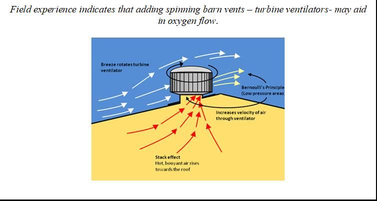
Recirculating Gravel Filter Systems - Recommended Standards and Guidance
 Effective Date: February 1, 2021

Recirculating gravel filters and recirculating gravel filters with vegetated denitrifying woodchip
bed may also be selected for removing up to 50% nitrogen in residential strength wastewater.
This may be a beneficial alternative in areas where nitrogen has been identified as a contaminant
of concern. For effective removal, influent from the septic tank must first be nitrified by
periodically dosing it from a recirculating/mixing tank to the surface of the filter where effluent
percolating through the filter draws in oxygen that promotes aerobic treatment. In addition to
having an ample oxygen supply, nitrification performance is a function of the relative wastewater
alkalinity and TN concentrations of the influent.

Field experience indicates that mixing tanks often have DO too high and BOD too low for
denitrification. If you are going to add carbon, you also need to add enough to consume the DO
that’s in the tank.

DOH 337-011 Page 8 of 53
Recirculating Gravel Filter Systems - Recommended Standards and Guidance
 Effective Date: February 1, 2021

1. Recirculating Gravel Filter (RGF)

 1.1. Performance Standards

 1.1.1. Performance Criteria

 1.1.2. When sited, designed, operated and maintained, consistent with these
 recommended standards and guidance a recirculating gravel filter or a
 recirculating gravel filter with a vegetative denitrifying woodchip bed, is expected
 to reduce residential strength effluent nitrogen by 50% and achieve Treatment
 Level C.

 1.1.3. Effluent from a recirculating gravel filter can be discharged to soil dispersal
 components with vertical separations of at least 24 inches in soil types 2 through 6
 and at least 60 inches in soil type 1.

 1.2. Application Standards

 These standards apply to on-site sewage systems with design flows less than 3,500 GPD.
 For systems with design flows from 3,500 to 100,000 GPD, standards in the LOSS rule
 (WAC 246-272B-00650) apply.

 1.2.1. Listing

 1.2.1.1. Recirculating gravel filters are public domain treatment technologies and
 are included in the Department of Health’s List of Registered On-site
 Treatment and Distribution Products as a Category 1 treatment component
 (designed to treat typical residential sewage). A 50% nitrogen reduction
 credit may be applied to residential strength effluent. The recirculating
 gravel filter may also be used as a Category 2 treatment component
 (designed to treat sewage with organic strength higher than typical
 residential sewage from both residential and non-residential sources.

 1.2.2. Permitting

 1.2.2.1. Installation, and if required, operational, permits must be obtained from the
 appropriate local health officer prior to installation and use.

 1.3. Design Standards

 1.3.1. Design Approval: Before construction can begin, the design must be approved by
 a local health or other appropriate jurisdiction. All site inspections before, during,
 and after the construction must be accomplished by local health, other appropriate
 jurisdiction, or by a designer or engineer appointed by the appropriate
 jurisdiction.

DOH 337-011 Page 9 of 53
Recirculating Gravel Filter Systems - Recommended Standards and Guidance
 Effective Date: February 1, 2021

 Figure 1 - Typical Layout of a Recirculating Gravel Filter

 RECIRCULATING
 SEPTIC TANK GRAVEL
 FILTER

 RECIRCULATING /

 M IXING TANK

 DRAINFIELD

DOH 337-011 Page 10 of 53
Recirculating Gravel Filter Systems - Recommended Standards and Guidance
 Effective Date: February 1, 2021

 Figure 2 – Cross-Section of a Typical Recirculating Gravel Filter

 Slots must be in the 12 o’clock position

 Vertical piping from the underdrain to the surface may help with rehabilitation of failed filters.

 1.4. Influent Characteristics

 1.4.1. Residential Wastewater: Recirculating gravel filters are suitable for treating
 residential strength wastewater. The filter will be smaller in size than an
 intermittent sand filter and may be preferred for this reason. Recirculating gravel
 filters are not as susceptible to hydraulic and biological overloading as
 intermittent sand filters.

 1.4.2. Non-Residential Wastewater: Recirculating gravel filters are suitable for high
 strength residential and light commercial wastewater where the BOD5 does not
 exceed 720 mg/L.

Some on-site sewage system professionals have reported recirculating gravel filters may be
susceptible to premature failure. Reduced treatment levels, or clogging if influent fats, oils, and
greases are elevated in wastewater loads or BOD5 approaches 720 mg/l. The Technical Review
Committee acknowledges these reports but concludes available r3search data is currently
inconclusive. Until modifications to the standards and guidance are made based on future
research and findings, it’s suggested that influent BOD5 not exceed 400 mg/l and fats, oils, and
greases not exceed 30 mg/l.

 1.5. Design Flow (Daily Wastewater Flow Estimates)

DOH 337-011 Page 11 of 53
Recirculating Gravel Filter Systems - Recommended Standards and Guidance
 Effective Date: February 1, 2021

 1.5.1. Residential: For all residential applications, a minimum wastewater design flow
 of at least 120 gallons/bedroom/day must be used.

 1.5.2. Non-Residential: For non-residential applications, a minimum wastewater design
 flow equal to 150% of the estimated design flow based on an average must be
 used.

 1.6. Treatment

 1.6.1. Primary Treatment

 1.6.1.1. For residential sewage, settleable and floatable solid separation must be
 achieved using a properly sized, registered, two-compartment septic tank
 with effluent baffle screening, or equivalent wastewater
 sedimentation/initial treatment unit.

 1.6.1.2. For wastewater from non-domestic sources, primary treatment other than a
 septic tank may be required if the influent to the gravel filter is not within
 the allowable limits for recirculating gravel filters.

Aerobic treatment or some other treatment process may be needed to modify the influent to the
recirculating gravel filter to within the range of residential septic tank effluent quality.

 1.6.2. Location Requirements: The minimum setback requirements for recirculating
 gravel filters are the same as required for sewage tanks (WAC 262-272A-0210).

 1.7. Filter Bed

 1.7.1. Media Specifications: Filter media must meet the fine gravel media specification
 for particle size graduation detailed in Appendix A, Section II. Media used in
 constructing a recirculating gravel filter must be accompanied with a written
 certification from the supplier that the media fully conforms to the media
 specifications listed in Appendix A as determined by ASTM C-136 and ASTM C-
 117.

 1.7.2. Filter Bed Sizing

DOH 337-011 Page 12 of 53
Recirculating Gravel Filter Systems - Recommended Standards and Guidance
 Effective Date: February 1, 2021

 1.7.2.1. Hydraulic Loading Rate: The loading rate must be calculated on the basis of
 the incoming BOD5. Repair, alteration, and expansion projects provide the
 opportunity to sample and test the actual wastewater. New sites must rely
 on wastewater strength estimates from similar facilities. The loading rate
 must be calculated as follows:

 1.7.2.2. Surface area of filter bed: The surface area must be determined by dividing
 the design flow estimate by the loading rate.

 1.7.2.3. Depth of media: The media depth must be a minimum of 24 inches.

 1.7.3. Surface of the Recirculating Gravel Filter: The surface of recirculating gravel
 filters differs from intermittent sand filters, sand-lined trenches and stratified sand
 filters since the surface (top) must remain open to air to encourage oxygenation of
 the filter. Cover soil may not be placed on top of the upper layer of drainrock in
 recirculating gravel filters.

 1.7.4. Monitoring Ports: Recirculating gravel filters must have a minimum of two
 monitoring ports. One must be placed at the bottom of the drainrock/top of the
 media interface (infiltrative surface of the gravel filter) or to the interior of the
 chamber if gravelless chambers are used. The other port must be placed at the
 bottom of underdrain system. See Appendix E for examples of monitoring ports
 and anchoring methods.
 1.7.5. Filter Bed Containment: The filter bed may be contained either in a synthetic
 membrane liner or an engineered concrete cast-in-place containment vessel.
 Design and construction must conform to the containment vessel standards set

DOH 337-011 Page 13 of 53
Recirculating Gravel Filter Systems - Recommended Standards and Guidance
 Effective Date: February 1, 2021

 forth in Appendix B for synthetic membrane liners or WAC 246-272C for cast-in-
 place concrete containment vessels.
 1.8. Effluent Distribution
 1.8.1. Pressure Distribution: A method providing pressure distribution with timed
 dosing throughout the recirculating gravel filter is required and must comply with
 pressure distribution standards and guidance. The distribution system and pump
 chamber must be designed according to the Recommended Standards and
 Guidance for Pressure Distribution or Recommended Standards and Guidance for
 Subsurface Drip Systems. This requirement applies to all pressure distribution
 related components.
 1.8.2. Effluent Application to the Filter Bed: The effluent must be applied to the layer of
 drainrock on top of the filter media by pressure distribution. In place of a layer of
 drainrock, effluent may be applied to the filter media by pressure distribution
 using a proprietary distribution product, such as a gravelless distribution or
 subsurface dripline product. When gravelless chambers are used, at least two
 inches of drainrock or pea gravel must be placed over the chambers for surface
 cover.
 1.8.3. When a proprietary distribution product, such as a gravelless distribution or
 subsurface dripline product, is used in place of drainrock in a recirculating gravel
 filter, only those distribution products on the current List of Registered On-site
 Treatment and Distribution Products may be permitted by the local health officer.

Field experience indicates that the 12 o’clock spray on the inside arch of gravelless chambers
provides a more even distribution of the effluent than using orifice shields

Recirculating gravel filter media may be utilized in lieu of drainrock in the top of the filter bed.

 1.9. Recirculating/Mixing Tank

 1.9.1. The recirculating/mixing tank must be on the Department of Health’s List of
 Registered Sewage Tanks.

 1.9.2. The volume of the recirculating/mixing tank is determined by the following:

 1.9.2.1. For residential systems: 150% of the daily wastewater design flow estimate.

 1.9.2.2. For non-residential systems: 100% of the daily wastewater design flow
 estimate.

 1.10. Recirculating Pump

 1.10.1. Console: The recirculating pump must be controlled by a timer with a dosing
 schedule that provides for frequent, cycled and uniform doses, allowing the
 influent/filtrate mixture to pass through the filter about five times for a 5:1 ratio
 before being discharged.

DOH 337-011 Page 14 of 53
Recirculating Gravel Filter Systems - Recommended Standards and Guidance
 Effective Date: February 1, 2021

Recirculation provides control of treatment processes by changes that can be made to the
recirculation ratios and dosing frequencies.

A 5:1 ratio means that 5 volumes are recirculated for every 1 volume of raw wastewater.

Typical pumping cycles are for one continuous cycle every 30 minutes (48 cycles per day) with
the off cycle set for approximately 25 minutes. The on cycle should be set so that the orifice
discharge per dose cycle does not exceed 1 gallon per orifice.

Both timer and float switch controls are required (see Figure 3). To protect the pump and the
distribution pipe network orifices, the outlet of the septic tank must include screening of the
effluent unless screening of the pump is provided (see standards and guidance for pressure
distribution systems for effluent screening).

In the event of low levels in the recirculating/mixing tank, to protect the pump by assuring
adequate pump submergence, a redundant off/low level alarm control float is recommended (see
Figure 3). The redundant off/low level alarm must be installed in accordance with the pump
manufacturer’s recommendations to assure adequate pump submergence.

In conditions where wastewater daily flows are highly variable, a pump control system equipped
with “peak” and/or “low” dose enable floats and circuits are recommended. These controls
respond to peak and low flow conditions by increasing or decreasing the dosing frequency when
high or low levels in the recirculating/mixing tank are reached and then reverting back to the
standard dosing cycle when these floats have returned to their “off” position.

Flow rate for recirculating pump: Recirculation ratios are not recommended to be greater than
8 (8:1). (DNR, MO). Low recirculation ratios range are not recommended to be lower than 3:1
to 4:1 (J. Anderson).

Iowa DNR suggest that a high ratio of 7:1 or 8:1 may deplete the alkalinity and pH so it may be
too low which may allow filamentous growth causing clogging of the orifices.

The recirculation ratio (RR) is the daily volume applied to the filter divided by the forward flow
volume. The RR usually ranges from 3 to 5, with 4 being typical (Tchobanoglous 1991; Loudon
1996). Systems should be designed for an RR of 4, but the pumps should be sized so that an RR of
5 is attainable.

Increasing the ratio will increase the dissolved oxygen which will control some filamentous
bacteria such as Thiothrix and Beggiatoa.

DOH 337-011 Page 15 of 53
Recirculating Gravel Filter Systems - Recommended Standards and Guidance
 Effective Date: February 1, 2021

 Figure 3 – Recirculating/Mixing Tank with a Splitter Valve

 1.10.2. The minimum recirculating pump flows, in gallons per minute, can be calculated
 by the following formulas:

 Daily Design Flow (GPD) x the recirculation ratio ÷ 1 = Through – filter flow (GPD)

 Through − filter flow (GPD)
 = Gallons per cycle
 pump cycles per day

 Gallons per cycle
 = Gallons per minute
 minutes per on cycle

 *Note that the pressure distribution network design in the recirculating gravel filter may
 result in a higher discharge rate.

 1.11. Treated Effluent (Filtrate) Collection and Discharge

 1.11.1. Filtrate may be collected and discharged from the bottom of the gravel filter by
 either a gravity-flow underdrain or a pump discharge underdrain. A gravity-flow
 underdrain is the preferred method for collecting and discharging the filtrate back
 to the recirculating tank. When gravel filters are membrane-lined, gravity-flow
 underdrains must exit through a boot. The boot and exit pipe must be installed and
 tested according to the standards in Appendix B.

 1.11.2. Filter to recirculating/mixing tank pipe sizing: The pipe from the filter to the
 recirculating/mixing tank can be sized using the Manning’s equation, which
 relates flow, pipe diameter, slope, and pipe smoothness. Typically it is expressed
 in the following manner:

DOH 337-011 Page 16 of 53
Recirculating Gravel Filter Systems - Recommended Standards and Guidance
 Effective Date: February 1, 2021

 Q = (1.49/n) A Rh2/3 S1/2
 Where:
 Q = Flow in pipe, cubic feet per second
 n = Manning roughness coefficient (dimensionless - assume 0.013 for PVC pipes)
 S = Slope of the pipe, feet per foot
 A = Cross-sectional area of flow, square feet = π D2/8 for half-pipe
 Rh = Hydraulic radius, feet = A/wetted perimeter of pipe, feet
 For gravity flow, assume the pipe is half full, so Rh = [(π/8) D2]/[π/2d] = D/4
 *For PVC pipes flowing half full Manning’s equation can be reduced to:
 Q = 17.9 D8/3 S1/2 or

 3/8
 D= 1
 17.9 2

 Where Q is in cubic feet per second, D is the diameter of the pipe in feet, S is
 feet/foot and engineers must perform all necessary conversions.

 1.11.3. Recirculation Flow Splitting Mechanisms: Effluent treated in the recirculating
 gravel filter collects at the bottom of the filter through an underdrain and a portion
 is returned to the recirculating/mixing tank. In a 5:1 recirculation ratio, the
 collected flow must be split to redirect 85% of the treated effluent back to the
 recirculating/mixing or septic tank. Balance of the treated effluent is routed to the
 soil dispersal component.

 1.11.4. Options and comments concerning flow splitting are noted in Appendix D.

To encourage mixing of fresh influent with partially treated recirculating return filtrate, the
return line from the filter should enter the recirculating/mixing tank at the same end of the tank
as the influent from the septic tank and at the opposite end from the recirculating pump.

2. Nitrifying Recirculating Gravel Filter with Vegetated Denitrifying Woodchip Bed

 2.1. Performance Standards

 2.1.1. When properly sited, designed, installed, operated, and maintained, a nitrifying
 recirculating gravel filter followed by a vegetated denitrifying woodchip bed
 consistent with these recommended standards and guidance is expected to achieve
 treatment performance equal to Treatment Levels N and C.

 2.1.2. Effluent from a nitrifying recirculating gravel filter followed by a vegetated
 denitrifying woodchip bed can be discharged to soil dispersal components with

DOH 337-011 Page 17 of 53
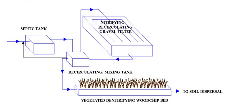
Recirculating Gravel Filter Systems - Recommended Standards and Guidance
 Effective Date: February 1, 2021

 vertical separations of at least 24 inches in soil types 2 through 6 and at least 60
 inches in soil type 1.

 2.2. Application Standards

 2.2.1. Listing: Nitrifying recirculating gravel filters followed by vegetated denitrifying
 woodchip beds are “public domain” treatment technologies and are included in
 the Department of Health’s List of Registered On-site Treatment and Distribution
 Products as a Category 1 treatment sequence (designed to treat typical residential
 sewage) meeting Treatment Levels C and N.

 2.2.2. Permitting: Installation and, if required, operational permits must be obtained
 from the appropriate local health officer prior to installation and use. The local
 health officer may permit a nitrifying recirculating gravel filter with vegetated
 denitrifying woodchip bed for removal of nitrogen in areas where nitrogen has
 been identified as a contaminant of concern.

 2.3. Design Standards

 2.3.1. Design Approval: Before construction can begin, the design must be approved by
 the local health officer. All site inspections before, during, and after the
 construction must be accomplished by local health, other appropriate jurisdiction,
 or by a designer or engineer appointed by the appropriate jurisdiction.

Figure 4. Layout of a Nitrifying Recirculating Gravel Filter and a Vegetated Denitrifying
Woodchip Bed

DOH 337-011 Page 18 of 53
Recirculating Gravel Filter Systems - Recommended Standards and Guidance
 Effective Date: February 1, 2021

The recirculated effluent may be returned to either the recirculating mixing tank, the septic tank,
or the sequence of the recirculation tank to the septic tank.

Figure 5. Cross-section of a Typical Nitrifying Recirculating Gravel Filter

 Slots must be in the 12 o’clock position

Field experience indicates that adding vertical piping from the underdrain to the surface may
help with rehabilitation of failed filters. Spinning barn vents (turbine ventilator) may aid in
oxygen flow.

Figure 6. Cross-section of a Typical Vegetated Denitrifying Woodchip Bed

 2.4. Influent Characteristics

DOH 337-011 Page 19 of 53
Recirculating Gravel Filter Systems - Recommended Standards and Guidance
 Effective Date: February 1, 2021

 2.4.1. Residential Wastewater: Nitrifying recirculating gravel filters are suitable for
 treating residential strength wastewater. In addition to being designed for nitrogen
 removal, the filters are typically smaller than intermittent sand filters, and may be
 preferred for this reason. Recirculating gravel filters are not as susceptible to
 hydraulic and biological overloading as intermittent sand filters.

 2.4.2. Non-Residential Wastewater: Nitrifying recirculating gravel filters are suitable for
 high strength residential and light commercial wastewater where the BOD5 does
 not exceed 400 mg/L and O&G does not exceed 30 mg/L

 2.5. Design Flow (Daily Wastewater Flow Estimates)

 2.5.1. Residential: For all residential applications, a minimum wastewater design flow
 of at least 120 gallons/bedroom/day must be used.

 2.5.2. Non-Residential: For non-residential applications, a minimum wastewater design
 flow equal to 150% of the estimated daily flow should be used.

 2.6. Primary Treatment

 2.6.1. For residential sewage, settleable and floatable solid separation must be achieved
 using a properly sized, registered, two-compartment septic tank with effluent
 baffle screening, or equivalent wastewater sedimentation/initial treatment unit.

 2.6.2. For wastewater from non-domestic sources, influent to the nitrifying gravel filter
 must be equivalent to residential strength septic tank effluent. The organic loading
 rate to the filter must not be more than 0.005 lb BOD/ft2/day.

 2.7. Location Requirements: The minimum setback requirements for nitrifying
 recirculating gravel filters and vegetated denitrifying woodchip beds are the same as
 required for sewage tanks (WAC 262-272A-0210).

 2.8. Filter Bed

 2.8.1. Media Specifications: Filter media must meet the fine gravel media specification
 for particle size graduation detailed in Appendix A, Section III. Media used in
 constructing a nitrifying recirculating gravel filter must be accompanied with a
 written certification from the supplier that the media fully conforms to the media
 specifications listed in Appendix A as determined by ASTM C-136 and ASTM C-
 117.

 2.8.2. Filter Bed Sizing

 2.8.2.1. Hydraulic Loading Rate: The loading rate to the nitrifying recirculating
 gravel filter for residential applications must not exceed 5.0
 gallons/day/square feet, using appropriate daily wastewater flow design
 estimate.

DOH 337-011 Page 20 of 53
Recirculating Gravel Filter Systems - Recommended Standards and Guidance
 Effective Date: February 1, 2021

 2.8.2.2. Surface area of filter bed: The surface area must be determined by dividing
 the design flow estimate by the loading rate.

 2.8.2.3. Depth of media: The media depth must be a minimum of 24 inches.

 2.8.3. Surface of the Nitrifying Recirculating Gravel Filter: The surface (top) of the
 recirculating gravel filters differ from the intermittent sand filter, sand-lined
 trenches, and stratified sand filters since the surface must remain open to air to
 encourage oxygenation of the filter. Cover soil must not be placed on top of the
 upper layer of drainrock in the recirculating gravel filters.

 2.8.4. Monitoring Ports: Nitrifying recirculating gravel filters must have a minimum of
 two monitoring ports. One must be placed at the bottom of the drainrock/top of
 the media interface (infiltrative surface of the gravel filter) or to the interior of the
 chamber if gravelless chambers are used. The other port must be at the bottom of
 the underdrain system. See Appendix E for examples of monitoring ports and
 anchoring methods.

 2.8.5. Filter bed containment: The filter bed may be contained either in a synthetic
 membrane liner or an engineered, designed concrete, cast-in-place containment
 vessel. Design and construction must conform to the containment vessel standards
 set forth in Appendix B for synthetic membrane liners or WAC 246-272C for
 cast-in-place concrete containment vessels.

 2.9. Effluent Distribution

 2.9.1. Pressure distribution: A method providing pressure distribution with timed dosing
 throughout the nitrifying recirculating gravel filter is required and must comply
 with pressure distribution standards and guidance. The distribution system and
 pump chamber must be designed according to the Recommended Standards and
 Guidance for Pressure Distribution or Recommended Standards and Guidance for
 Subsurface Drip Systems. This requirement applies to all pressure distribution
 related components.

 2.9.2. Effluent application to the filter bed: The effluent must be applied to the layer of
 drainrock on top of the filter media by pressure distribution. In place of a layer of
 drainrock, effluent may be applied to the filter media by pressure distribution
 using a proprietary distribution product, such as a gravelless distribution or
 subsurface dripline product. When gravelless chambers are used, at least two
 inches of drainrock or pea gravel must be placed over the chambers for surface
 cover.

 2.9.3. When a proprietary distribution product, such as a gravelless distribution or
 subsurface dripline product, is used in place of drainrock in a recirculating gravel
 filter, only those distribution products on the current List of Registered On-site
 Treatment and Distribution Products may be permitted by the local health
 jurisdiction.

DOH 337-011 Page 21 of 53
Recirculating Gravel Filter Systems - Recommended Standards and Guidance
 Effective Date: February 1, 2021

Nitrifying recirculating gravel filter media may be utilized in lieu of drainrock in the top of the
filter bed.

 2.10. Recirculating/Mixing Tank

 2.10.1. The recirculating/mixing tank must be on the Department of Health’s List of
 Registered Sewage Tanks

 2.10.2. The volume of the recirculating/mixing tank is determined by the following:

 2.10.2.1. For residential systems: 150% of the daily wastewater design flow estimate.

 2.10.2.2. For non-residential systems: 100% of the daily wastewater design flow
 estimate.

 2.11. Recirculating Pump

 2.11.1. Controls: The recirculating pump must be controlled by a timer with a dosing
 schedule that provides for frequent, cycled and uniform doses, allowing the
 influent/filtrate mixture to pass through the filter about six times before being
 discharged to the vegetated wood chip bed.

Recirculation provides control of treatment processes by changes that can be made to the
recirculation ratios and dosing frequencies. Typical pumping cycles are for one continuous cycle
every 20 to 30 minutes (48 to 72 cycles per day) with the “pump on” time set for 1 to 3 minutes.
The “pump on” cycle should be set so that the orifice discharge per dose cycle does not exceed 1
gallon per orifice.

Both timer and float switch controls are required (see Figure 7). To protect the pump and the
distribution pipe network orifices, the outlet of the septic tank must include screening of the
effluent unless screening of the pump is provided (see standards and guidance for pressure
distribution systems for effluent screening).

In the event of low levels in the recirculating/mixing tank, to protect the pump by assuring
adequate pump submergence, a redundant off/low level alarm control float is recommended as
shown in Figure 7. The redundant off/low level alarm must be installed in accordance with the
pump manufacturer’s recommendations to assure adequate pump submergence.

In conditions where wastewater daily flows are highly variable, a pump control system equipped
with “peak” and/or “low” dose enable floats and circuits is recommended. These controls
respond to peak and low flow conditions by increasing or decreasing the dosing frequency when
high or low levels in the recirculating/mixing tank are reached and then reverting back to the
standard dosing cycle when these floats have returned to their “off” position.

DOH 337-011 Page 22 of 53
Recirculating Gravel Filter Systems - Recommended Standards and Guidance
 Effective Date: February 1, 2021

 Figure 7. Example of a Recirculating/Mixing Tank with a Recirculating Ball Valve

 2.11.2. Flow rate for recirculating pump: The minimum recirculating pump flows, in
 gallons per minute, can be calculated by the following formulas:

 2.12. Treated Wastewater (Filtrate) Collection and Discharge

DOH 337-011 Page 23 of 53
Recirculating Gravel Filter Systems - Recommended Standards and Guidance
 Effective Date: February 1, 2021

 2.12.1. Recirculation Flow Splitting Mechanisms: Effluent treated in the recirculating
 gravel filter collects at the bottom of the filter through an underdrain and a portion
 is returned to the recirculating/mixing tank.

 2.12.2. The collected flow must be split to redirect 75-85% of the treated effluent back to
 the recirculating/mixing tank or septic tank. The balance of the treated effluent is
 routed to the vegetated denitrifying woodchip bed. Options and comments
 concerning flow splitting are noted in Appendix D.

A return method to the septic tank that minimizes stirring of solids is to increase the diameter of
the return line for at least 10 feet prior to the sewage tank.

To encourage mixing of fresh influent with partially treated recirculating return filtrate, the
return line from the filter should enter the recirculating/mixing tank near the influent from the
septic tank

DOH 337-011 Page 24 of 53
Recirculating Gravel Filter Systems - Recommended Standards and Guidance
 Effective Date: February 1, 2021

 Alkalinity Addition

 The nitrification reaction (the conversion of ammonia to nitrate) consumes 7.1mg/L
 of alkalinity for each mg/L of ammonia nitrogen oxidized. Calcium carbonate may
 need to be added to the water supply to achieve optimal nitrification. (OSWW final
 report)

 Approximate Septic Tank Influent Alkalinity Needed to Produce Nitrified Effluent
 NH3-N Concentration of 1.0 mg/L as a Function of the Influent TN Concentration

 Influent Alkalinity if
 denitrification is in Influent alkalinity if
 Influent separate tank/system denitrification is present
 TN, mg/L-N as CaCO3, mg/L as CaCO3, mg/L
 80 557
 70 487 313
 60 416 265
 50 345 218
 40 275 170
 30 204 123

 Recirculating gravel filter recirculating/mixing tanks and septic tanks generally have
 conditions that promote denitrification, including anoxic conditions (low dissolved
 oxygen) and biodegradable carbon. However, denitrification tends to be carbon
 limited because much of the CBOD is removed by aerobic microbial respiration,
 which is conducive to nitrification in the filter, and is no longer available for
 denitrification in the recirculating/mixing tank. Consequently, nitrified RGF effluents
 typically must have an external carbon source added to supply enough energy to
 enhance denitrification. One source of carbon is the septic tank liquid. The vegetated
 denitrifying woodchip bed uses woodchips as a readily available solid carbon source
 for denitrification following a nitrifying recirculating gravel filter to overcome this
 problem. However, this new nitrogen reduction option is not without limitations or
 additional field evaluation needs.

 2.13. Vegetated Denitrifying Woodchip Bed (VDWB)

 2.13.1. Media Specifications

 2.13.1.1. Woodchip media must be of alder wood, free of bark, leaves, twigs, dirt,
 rocks, and foreign material and not from treated wood.

DOH 337-011 Page 25 of 53
Recirculating Gravel Filter Systems - Recommended Standards and Guidance
 Effective Date: February 1, 2021

 2.13.1.2. The particle size must be 0.5 to 3 inches in length, not less than 0.375
 inches in width, and not less than 0.0625 inches thick.

 2.13.1.3. At least 85% by volume, must conform to the size specified.

 2.13.2. Woodchip Bed Sizing

 2.13.2.1. Hydraulic Loading Rate: The loading rate must not exceed 8
 gallons/day/square foot, based on the top area of the bed.

 2.13.2.2. Surface area of filter bed: The surface area must be determined by dividing
 the daily design flow estimate by the loading rate.

 2.13.2.3. Aspect (Length to Width) Ratio of Bed: The VDWB must have an aspect
 ratio ranging from 5:1 to 4:1 to ensure proper water flow through the bed.

 2.13.2.4. Depth (thickness) of Woodchip Media

 2.13.2.4.1. A minimum depth of 40 inches of woodchip media must be placed in
 all VDWBs. The water level should be maintained at least 6 inches
 below the surface of the woodchips at all times to prevent odors and
 for disease vector control. The water level must be set at least 34
 inches above the VDWB bottom (see Figure 8).

 2.13.2.4.2. The surface of the woodchip media should be level.

Research has shown cooler temperatures reduce microbial action, reducing denitrification
processes in the VDWB. Steps can be taken to help reduce the VDWB sensitivity to temperatures
and the risk of freezing in areas with seasonal cold weather. These steps may include installing
one to two inch rigid foam panels around the perimeter of the VDWB and RGF containment
vessels, using lids with 2-inch foam insulation on sewage tanks, and/or placing a 6-inch layer of
straw mulch layer on top of the woodchip media.

Design standards for VDWB sizing provide a hydraulic retention time (amount of time effluent
needs to stay in the VDWB) of approximately two days. The retention time inside the VDWB is
important, particularly at low operating temperatures, because there must be sufficient time for
the desired denitrification processes to occur. Longer retention times provide excellent nitrate
removal. However, studies show that sulfate reduction can occur if the water stays in the VDWB
too long, when nitrate has been almost completely removed, and often at high temperatures.
Sulfate reduction can be a concern because it represents a loss of carbon for denitrifiers and it
produces hydrogen sulfide that can be a noxious gas.

VDWBs can be designed and maintained to minimize sulfate reduction by retaining low
concentrations of nitrate in the effluent ( e.g.; 1.0 – 2.0 mg/L nitrate). If hydrogen sulfide odor
(i.e.; a rotten egg smell) is noted inside the flow control basin on an on-going basis, the water

DOH 337-011 Page 26 of 53
Recirculating Gravel Filter Systems - Recommended Standards and Guidance
 Effective Date: February 1, 2021

level in the VDWB should be lowered to obtain a high enough flow rate to not fully reduce
nitrate in the treated effluent.

On sites known to have extreme low flow conditions, the VDWB also can be designed with flow
splitting between two or more equally sized beds to lessen the impact on the cattail plants if
VDWB water level lowering is needed. See Section 2.4.5.2 Water Level Adjustment Pipe for
water level adjustment details.

 Figure 8. Cross-section Detail of a Typical Vegetated Denitrifying Woodchip Bed

 2.13.3. Woodchip Bed Containment

 2.13.3.1. The bed slope bottom must be flat to the horizontal plane.

 2.13.3.2. The filter bed may be contained either in a synthetic membrane liner, or an
 engineered-designed, concrete, cast-in place containment vessel. Design and
 construction must conform to the containment vessel standards set forth in
 Appendix B.

Due to the hydrostatic pressure produced by the water depth in a VDWB, a PVC boot at the
bottom of outlet of end of a VDWB can be more prone to leaking than a boot in a RGF
underdrain system. When installing boots to penetrate a liner, the manufacturer’s installation
instructions must be followed exactly. Orienting the boot so the stainless-steel clamps are inside
the liner of a VDWB instead of the outside may help prevent boot leakage.

 2.13.4. Woodchip Bed Inlet End and Outlet End Manifolds

 2.13.4.1. Inlet End Manifold: A high capacity gravelless chamber placed along the
 entire bottom width of the inlet end serves as an inlet manifold in the
 VDWB. Septic tank effluent enters through the side of the VDWB and
 flows downward into the top midpoint of the chamber. The invert of the

DOH 337-011 Page 27 of 53
Recirculating Gravel Filter Systems - Recommended Standards and Guidance
 Effective Date: February 1, 2021

 inlet pipe entering the VDWB is a minimum of 3 inches above the top of
 the 3-inch PVC water-level-adjustment pipe in the water-level control
 basin. The chamber distributes influent evenly across the width of the
 VDWB. The interior of chamber allows for the settling of solids at the inlet
 end of the VDWB and later pumping of the solids during maintenance.

 2.13.4.2. Monitoring Port: A 4-inch diameter monitoring port is part of the influent
 inlet pipe connected to the top of the chamber. The port is brought to grade
 and covered with a removable cap providing access to the interior of the
 chamber from the top of the VDWB as shown in Figure 8.

 2.13.4.3. Influent Distribution: The VDWB may be gravity-fed or pressure-dosed to
 the chamber inlet manifold. Pressure dosing allows the VDWB to be placed
 at an elevation higher in the landscape than the RGF but necessitates the use
 of an additional pump.

Influent may be discharged to the gravelless chamber placed at the bottom of the VDWB inlet by
either a gravity fed or pressure-dosed distribution system. When pressure dosing, the individual
dose volume to a VDWB must be kept to a maximum 10 gallons per dose.

“Field cut” the chamber to fit the bed’s width and place it flush against the sidewall of the bed.
Cover the ends with a thick geotextile fabric to prevent woodchips from entering the inside of the
chamber and to protect the liner from any rough-cut edges on the chamber.

Chamber end caps may be used, but it may be difficult to “field fit” the cut end without the use of
fabric, and approximately one foot is lost on each end of the chamber due to the end caps.

 2.13.4.4. Outlet End Manifold: After effluent travels horizontally across the
 woodchips of the VDWB, a submerged vertically placed 4-inch diameter
 slotted PVC pipe collects the treated effluent at the center outlet end of the
 VDWB. Slots should be cut ¼ inch wide and 2.5 inches deep at every 4
 inches on center. To avoid the slots being pushed against the liner, they
 must be faced towards the inlet end of the bed. The distal end of the slotted
 pipe must be brought to grade and covered with a removable cap. The 4-
 inch diameter solid PVC outlet pipe exiting the VDWB is located 4 inches
 from the bottom of the bed (see Figure 8).

 2.13.5. Woodchip Bed Water-Level Control Basin

 2.13.5.1. From the VDWB, denitrified effluent goes to a watertight, water-level
 control basin that allows the water level in the bed to be set at least 34
 inches above the VDWB bottom and 6 inches below the surface of the
 woodchips. This is important because the water level must remain below
 the surface of the bed in order to prevent odors yet be high enough to
 prevent plant roots in the bed from drying or freezing.

DOH 337-011 Page 28 of 53
Recirculating Gravel Filter Systems - Recommended Standards and Guidance
 Effective Date: February 1, 2021

 2.13.5.2. Water-Level Adjustment Pipe: A water-level adjustment standpipe located
 inside the basin is used to adjust the operational depth in the VDWB. The
 pipe assembly consists of a 4-inch PVC Tee with end screw cap; a 4-inch x
 3-inch PVC-to-PVC flexible sewer coupler reducer and 3-inch PVC pipe at
 the top to adjust and maintain the water level. Effluent overflows the top of
 the 3-inch standpipe and into the water-level control basin when additional
 wastewater enters the VDWB (see Figure 9).

 2.13.5.3. Treated Effluent Discharge: Effluent is discharged from the bottom of the
 water-level control basin by a gravity-flow outlet pipe. After treatment in
 the VDWB, effluent travels to a soil dispersal component for further
 treatment and dispersal (see Figure 9).

 Figure 9. Example of a Water-Level Control Basin

 2.13.6. Woodchip Bed Vegetation

 2.13.6.1. Roles of Plants: Plants will absorb some of the nutrients from the effluent,
 and they also play a role in carbon cycling and insulating against seasonal
 low temperature effects. Plants root structure helps water flow and prevents
 woodchip media settling.

 2.13.6.2. Planting: After filling the VDWB with water at a depth of 6 inches below
 the surface of the woodchip media, cattails (Typha latifolia) must be planted
 into the woodchips in rows with a density of approximately one plant per
 square foot. The rows should be perpendicular to the direction of effluent
 subsurface flow. Be sure the roots are free of soil and debris before placing
 them in the woodchip media. While keeping the cattail shoots above the

DOH 337-011 Page 29 of 53
Recirculating Gravel Filter Systems - Recommended Standards and Guidance
 Effective Date: February 1, 2021

 surface of the woodchips, ensure the roots are inserted into the bed at a
 depth greater than 6 inches.

It is recommended to fill the VDWB with water before installing the plants to keep the roots
saturated to prevent them from dying.

When planting the cattails, always plant to obtain a uniform plant cover over the entire top of the
VDWB. To accomplish this, place the rows and cattails 12 inches apart and staggered 6 inches.
Ensure the plants are a depth (greater than 6 inches) where roots are in the water.

The cattails should be planted in the spring for best opportunity for survival. If after six weeks
the plants do not seem to be taking hold and growing, replant in between the original plants in a
similar pattern.

Living and dead plant material should never be removed from the VDWB as this material is
necessary for nitrogen removal.

3. Operation and Maintenance Standards

 3.1. Management

 3.1.1. The local health officer may require a maintenance agreement with supporting
 legal documents before approving a proposed recirculating gravel filter system.
 Maintenance agreements are recommended when, in the opinion of the local
 health jurisdiction, optimum operation of a recirculating gravel filter system is
 assured by such an agreement.

 3.1.2. Owner Responsibilities: The owner of the residence or facility served by a
 recirculating gravel filter system is responsible for assuring proper operation and
 providing timely maintenance for all components of the on-site wastewater
 treatment and soil dispersal system. This includes inspecting the entire system at a
 frequency appropriate for the site conditions and the type of on-site sewage
 system as specified by the local health jurisdiction. Contact the local health
 department/district to find the required qualifications of a person to perform any
 specialized monitoring and maintenance activities.

 3.2. Operation and Maintenance (O&M) Manual

 3.2.1. An O&M manual for the recirculating gravel filter system must be provided by
 the system designer. The manual must contain the following, at a minimum:

 3.2.1.1. The system owner’s responsibilities, including established system
 operation, inspection, record keeping, reporting, and permit requirements.

DOH 337-011 Page 30 of 53
You can also read