Bicycle Detection A review of available technologies and practical experience to aid in the creation of smarter intersections that work for all ...
←
→
Page content transcription
If your browser does not render page correctly, please read the page content below
PERSPECTIVES IN PRACTICE

Bicycle Detection
A review of available technologies and practical experience to aid in
the creation of smarter intersections that work for all users

SUMMARY
Across the United States, approximately two-thirds of reported bicycle crashes happen at intersections. Detecting the
presence of people bicycling at or approaching signalized intersections and roadway crossings can offer traffic engineers
additional tools and flexibility to improve the comfort and safety for this vulnerable user group. This white paper provides
a deeper discussion on the various technologies that are available and provides insight on their strengths, weaknesses and
practical applications.

Contributors:

Joe Gilpin, Vice President
Tobin Bonnell, PE, PTOE, Engineering Associate
Matt Fralick, PE, PTOE, Senior Engineer
Kirk Paulsen, PE, Senior Engineer
Lindsay Zefting, PE, Principal
ALTA

                             As a global leader in mobility innovation for
                              25 years, Alta helps make positive changes
                             in communities to empower all people to live
                              active, healthy lives. We connect people to
                               places by working across disciplines and
                              scale to address social equity, access, and
                                       environmental resilience.

© Alta Planning + Design, 2021.

Bicycle Detection by Alta Planning + Design is licensed under a Creative Commons Attribution-NoDerivatives 4.0 International License.

Disclaimer: The design details, recommendations and conclusions in this document are based on interviews with city staff throughout North
America, Alta project experience, and industry design guidance. This white paper uses design resources and discoverable original research by
various institutions to make conclusions, though it is possible that other research that may be relevant was not identified. Engineering judgment
should always be used in roadway and signal design decisions.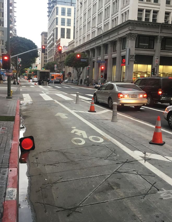
CONTENTS

SUMMARY .  .  .  .  .  .  .  .  .  .  .  .  .  .  .  .  .  .  .  .  .  .  .  .  .  .  .  .  .  .  .  .  . 1
01 INTRODUCTION  .  .  .  .  .  .  .  .  .  .  .  .  .  .  .  .  .  .  .  .  .  .  .  .  .  . 5
        Why Bicycle Detection?  . . . . . . . . . . . . . . . . . . . . . . . . . . . . . . . . . . . . 5

02 RESOURCES .  .  .  .  .  .  .  .  .  .  .  .  .  .  .  .  .  .  .  .  .  .  .  .  .  .  .  .  . 7
03 DETECTION GUIDANCE .  .  .  .  .  .  .  .  .  .  .  .  .  .  .  .  .  .  .  .  . 9
        Loop Detectors  . . . . . . . . . . . . . . . . . . . . . . . . . . . . . . . . . . . . . . . . . . 10
        Push Buttons . . . . . . . . . . . . . . . . . . . . . . . . . . . . . . . . . . . . . . . . . . . . 16
        Microwave/Radar . . . . . . . . . . . . . . . . . . . . . . . . . . . . . . . . . . . . . . . . 20
        Video . . . . . . . . . . . . . . . . . . . . . . . . . . . . . . . . . . . . . . . . . . . . . . . . . . . 24
        Infrared . . . . . . . . . . . . . . . . . . . . . . . . . . . . . . . . . . . . . . . . . . . . . . . . . 28
        In-Ground Radar . . . . . . . . . . . . . . . . . . . . . . . . . . . . . . . . . . . . . . . . . 30
        Bicyclist App - Broadcast Presence . . . . . . . . . . . . . . . . . . . . . . . . . 32

04 ENHANCEMENTS  .  .  .  .  .  .  .  .  .  .  .  .  .  .  .  .  .  .  .  .  .  .  .  . 35
        Bicyclist Detector Pavement Markings . . . . . . . . . . . . . . . . . . . . . . 35
        Bicycle Detection Confirmation Indication  . . . . . . . . . . . . . . . . . . 38
        Bicycle Facility Regulatory Blank-out Signs
        and Warning Beacons . . . . . . . . . . . . . . . . . . . . . . . . . . . . . . . . . . . . . 40
        Physical Amenities To Encourage Detection . . . . . . . . . . . . . . . . . 41

05 CONCLUSION .  .  .  .  .  .  .  .  .  .  .  .  .  .  .  .  .  .  .  .  .  .  .  .  .  .  . 43
06 REFERENCES  .  .  .  .  .  .  .  .  .  .  .  .  .  .  .  .  .  .  .  .  .  .  .  .  .  .  . 45

                                                                                                                         BICYCLE DETECTION | 3
Tucson, AZ

4 | ALTA PLANNING + DESIGN
01 INTRODUCTION
This white paper is intended as a resource for transportation practitioners who are seeking more detailed information on
the various types of signal detection families and the considerations that would impact the selection and configuration of
these technologies to detect bicyclists. While guidance on this subject exists, it is fragmented and does not comprehensively
provide a full understanding of the capabilities and limitations of each type of detection. This white paper builds upon
existing literature on the subject and combines it with practical experience with the hope it will help guide successful
intersection projects and expand the industry knowledge base.
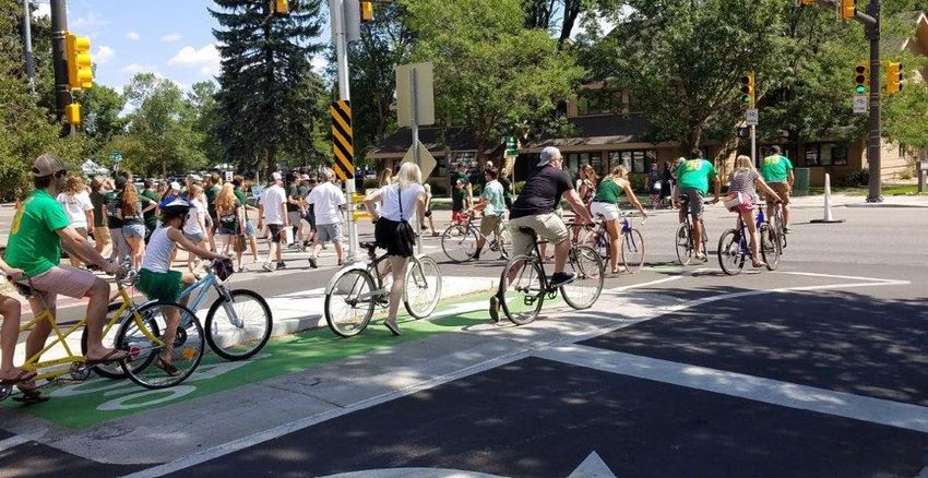
Why Bicycle Detection?
In many US and Canadian cities, expanding intersections is
either impossible or undesirable. Traffic engineers are being
asked to provide intersection solutions that process more
users more efficiently while adapting and integrating new
facility types like separated bike lanes and dedicated transit
lanes. There is a substantial diversity of technologies, both
old and new, that give the traffic engineering profession
tools to make North American signalized intersections
safer, more efficient, and adaptive to changing needs and
prevailing conditions. Detecting the presence of bicyclists
at signalized intersections can provide many benefits,
including:
• Reduction of the need for bicyclists to mount the
sidewalk or position in a travel lane to call a signal
• Improvement in signal compliance by people bicycling
• Ability to call exclusive phases, such as bicycle signals,
only when actuated to minimize unnecessary delay to
other users
• Ability to detect an approaching bicyclist in advance of
the intersection and calling a special phase or extended
phase timing prior to arrival to minimize bicyclist delay
These bicyclists are waiting outside of the loop detector and may
• Ability to extend the minimum green and/or clearance
not be detected at this signal
intervals to allow a bicyclist to safely clear an
intersection should the vehicular timing not be sufficient
• Activation of crossing devices such as bicycle specific
signals, Hybrid Beacons and Rectangular Rapid Flashing
Beacons
• Activation of special electronic warnings for motorists
to indicate bicyclist presence (flashing beacons or
blank-out signs)
• Facilitate the ability to collect real-time continuous
counts of bicycle activity
BICYCLE DETECTION | 5
Los Angeles, CA

6 | ALTA PLANNING + DESIGN
02 RESOURCES
This section briefly summarizes the main industry guidance and studies covering bicycle detection that were consulted prior
to drafting the content of this white paper. Additional references and studies are cited throughout this white paper and can be
found in the references section.

In 2006, the Federal Highway Administration (FHWA)
published the third edition of the Traffic Detector Handbook.
Chapter 4 of this handbook describes in depth the various
types of inductance loop configurations for the detection of
large and small vehicles in regards to design considerations
and controller operations (FHWA, 2006).

The most current edition of the MUTCD, last published
in 2009, has some guidance on signage and pavement
markings associated with bicycle detection (MUTCD, 2009).

In 2012, the American Association of State Highway and
Transportation Officials released the fourth edition of the
Guide for the Development of Bicycle Facilities. The guide
covers a range of topics from the planning and design
to the maintenance and operations of bicycle facilities.
In particular, Section 4.12.5 of the Guide gives a quick
overview of the different forms of detection methods
commonly used at traffic signals, including inductance
loops, video detection, and radar. (AASHTO, 2012).

The second edition of the Urban Bikeway Design
Guide, published by the National Association of City
Transportation Officials (NACTO) in 2012 provides design
guidelines for the different types of bicycle facilities. The
subsection of signal detection and actuation in the bike
signals chapter briefly covers the different methods of
detection for bicyclists at intersections, but focuses mainly
on inductance loop placement and the placement of
pavement markings to indicate where bicyclists should stop
to achieve the best actuation (NACTO, 2012).

This white paper also utilized the experience of signal
professionals at the City of Portland and the City of Austin,
as well as several other recent interviews including the
City of Fremont. Alta also made contact with many of
the equipment vendors to whom we are grateful for their
assistance. So as not to be a source of advertisement or
favor, this white paper was written to be neutral and does
not directly reference any specific vendor or product.

                                                                                                                BICYCLE DETECTION | 7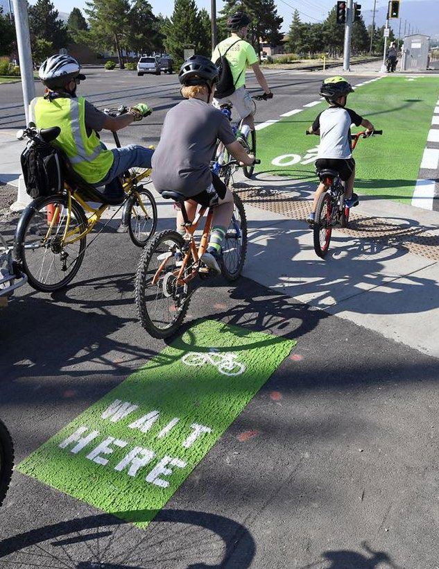
Durango, CO

8 | ALTA PLANNING + DESIGN
03 DETECTION GUIDANCE
This section provides a detailed summary of each of the common families of signal detection applicable to bicyclists. This
resource is intended to provide not only enough detail to understand the basics of the technology, but also to highlight key
design, installation, and contextual considerations. Some discussions have an “Additional Technical Detail” section, which
provides information that may only be relevant to traffic engineers and signal technicians. Exhibit 1 conveys a contextual
detection capability matrix that is specific to the detection of bicycles. Criterion highlighted in green indicates that the
detection family is ideal for the context/use. Red indicates that the detection family is not well suited to the context/use.
Orange indicates that the detection family may be well suited depending on installation, with additional guidance provided
in this section for clarification.

                                                                                                                            Infrared Video
                                                                                         Push Buttons

                                                                                                                                             Microwave

                                                                                                                                                         In-Ground
                                                                                                        Inductive
                                                                                                        Loops

                                                                                                                                                         Radar
                                                                                                                    Video
 Capabilities / Limitations
 Detect Bicyclist in Snow/Fog/Whiteout
 Distinguish Bike from Vehicle (in shared lane)
 Suitability to Count Bicyclists
 Suitability to Distinguish Bicyclist Directionality
 Suitability to Detect Low Metal Bicycle
 Suitability to Extend Green or Clearance Time
 Shared Travel Lanes
 Shared Travel Lane
 On-Street Bikeways
 Conventional Bike Lane (at curb)
 Conventional Bike Lane (left of right only lane)
 One-way Separated Bike Lane Approach (Inc Protected Intersection)
 Two-way Separated Bike Lane Approach (Inc Protected Intersection)
 Bike Box
 Two Stage Turn Queue Box
 Jug Handle (Turn Queue Box)
 Raised Bikeways
 One-way Separated Bike Lane Approach
 Two-way Separated Bike Lane Approach
 Shared Use Path (differentiate bikes from pedestrians)
 Bicycle Specific Crossing Treatments
 Toucan Crossing
 RRFB or PHB Crossing from curb

                   Ideal candidate for use

                   Can be configured depending on context, may not be ideal or may require additional detectors
                   Generally not suitable for context

                                                                                                                                                         BICYCLE DETECTION | 9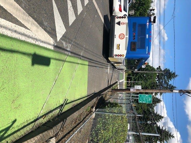
Loop Detectors                                                          Overview

        Controller Compatibility   High                                        Inductance loops (loops) are one of the most commonly
        Installation Complexity    Moderate to High                            used methods of detecting large and small vehicles on
        Functionality              Presence (Yes)                              roadways. They are relatively inexpensive and provide
                                   Counts (Yes)                                a high level of reliability for detection. Inductance loops
                                   Directionality (Yes)                        consist of an electrically conductive wire loop that is formed
                                   Distinguish Multiple Bikes (No)
                                                                               into a pattern inset in the pavement. An alternating current
        Durability                 Depends on surrounding material (asphalt/
                                                                               runs through the loop, creating an electrical circuit with
                                   concrete), and climate (extreme heat or
                                                                               inductance. Inductance is defined as the property of an
                                   freeze/thaw cycles)
                                                                               electric circuit by which an electromotive force is induced
        Ideal Applications         Anywhere a bicyclist is in an exclusive
                                   space and the loop can be tuned             in it as the result of a changing magnetic flux. Based on this
                                   accurately                                  property, when a ferrous item, such as a vehicle, overlaps
                                                                               the circuit, the magnetic flux changes and can be measured.
                                                                               A detector card inside the traffic signal cabinet measures
       Strengths                                                               this change and places a call to the signal controller.
       • Low cost                                                              Many states require detection of motorcycles and bicycles
       • Reliable                                                              at intersections, as to not trap these users on actuated
                                                                               approaches and create compliance issues. With some
       • Different winding patterns depending on context                       modern bicycles being constructed mainly of carbon fiber,
       • Can be used for both vehicles and bicyclists                          aluminum, or other non-ferrous materials, engineers prefer
                                                                               certain loop patterns that create “sweet spots” with a higher
       • Can be configured to provide counts                                   number of wire turns and the most potential to detect the
       • Accuracy not impacted by weather conditions                           change in inductance. To help position bicycles in the best
                                                                               location, pavement markings can be used to indicate the
       • Can be used to call bicycle-specific crossing devices from            optimal position to place the bicycle for detection. See later
         shared areas with pedestrians                                         section on detector symbol markings.

       Weaknesses                                                              Installation considerations/implications
       • Installation requires lane closures
                                                                               The installation of loops is straightforward but requires
       • Freeze/thaw conditions can lead to pavement cracking                  lane closures for approximately two to four hours per
         around the saw cut                                                    installation. Installation consists of sawcutting the shape
                                                                               of the desired loop path into the pavement approximately
       • Extreme heat that can deform asphalt can impact loop
                                                                               two to four inches (five to ten centimeters) deep. Once
         function
                                                                               the sawcut is blown clean, the wire can be wound in and
       • Shared lanes with large volumes of heavy vehicles can                 compressed into the sawcut using a specialized wheel or
         result in warped pavement and broken loops                            other tool. Once the number of turns specified is achieved,
                                                                               a foam or sealant is placed on top to prevent water damage.
       • Sealant can pull out and water damage can occur
                                                                               Conduit and two-pair wire leading from the controller to a
       • Can pick up false activations from adjacent lanes                     pull box on the side of the road adjacent to the loops will
                                                                               need to be provided to splice the lead-in wire from the
       • May require sensitivity adjustments to ensure proper
                                                                               loops to the two-pair wire in the pull box connecting to the
         working order
                                                                               controller.

10 | ALTA PLANNING + DESIGN
Pattern Configuration
The three most commonly used patterns that have been
designed to detect bicycles are the “Type D” loop, the
“Type Q” loop, and the Parallelogram loop. The “Type D”
and “Type Q” loops were eventually adopted by Caltrans
(California Department of Transportation) and further
tested by the FHWA in the study “Making Signal Systems for
Cyclists” (2008). Other commonly used patterns for motor
vehicle detection include the “Type A” (square) and “Type
E” (circular). Both of these patterns are not optimized for
bicycle detection and have narrow “sweet spots.”
“Type D” loops were created to help detect bicycles
and motorcycles better than standard loops for vehicles.
In most loop patterns, the optimal place for a bike to be
detected is directly on top of the saw cut. The “Type D”
loop is constructed diagonally to the travel lane so that
when a bicycle enters the loop, they will automatically
be positioned for the best detection. Per further studies
(Shanteau, 2008), the “Type D” loop does an excellent job
of rejecting vehicles in adjacent lanes. One issue with these
types of loops are the sharp turns required based on the
pattern during installation. Type D Loop in Huntsville, AL
= Detection Sweet Spot
27”
30”
15”
27” 30” 15”
Winding Detail Sawcut Detail
Type D Loop Detector Configuration
BICYCLE DETECTION | 11“Type Q” loops are modified quadrupole loops that help
detect bicyclists better. A quadrupole loop is a pattern of
loop that allows the magnetic field to have four magnetic
poles. Based on this design, bicyclists would have to ride
directly over the saw cut to have the best chance of being
detected. The “Type Q” loop was designed to be a six-foot
by six-foot pattern cut into two separate three-foot by
six-foot rectangles and rotated to be perpendicular to the
travel lane. By adjusting the shape of the rectangle and the
rotation of the saw cut, this allows the optimal detection
zone to be directly in the travel path of bicyclists. Like
“Type D” loops, the “Type Q” loop does an excellent job
of rejecting vehicles in adjacent lanes (Shanteau, 2008).
Additionally, the “Type Q” loop is easier to install and does
Type Q Loop in San Luis Obispo, CA
not require the same sharp angles as the “Type D” loop. One
disadvantage to the “Type Q” loop is that bicyclists just off
the loop will not be detected due to the wrapping of the
wires and partial cancellations of the magnetic field.
= Detection Sweet Spot
36” 36”
72”
12”
12”
Winding Detail Sawcut Detail
Type Q Loop Detector Configuration
12 | ALTA PLANNING + DESIGNThe parallelogram loop is simpler to install than the “Type
D” loop and provides reliable detection for bicycles. The
loop can also differentiate between bicyclists and motor
vehicles by the characteristics of the change in inductance.
The parallelogram loop can be a variety of widths and
three to six feet long, set at a 45 degree angle for shared
use lanes, or can be four feet wide with the remaining
dimensions constant to fit in a bike lane. The sawcut detail
below depicts two pattern types for a shared lane use or in
a bike lane. Based on the shape of the parallelogram loop,
bicycles will naturally pass over the sensitive points on the
loop, providing reliable detection.
Parallelogram Loop Detector Configuration in Portland, Oregon
detects bicyclists and vehicles entering this mixing zone. This
location puts in a locking call and extended green for bicyclists.
(Credit: Oliver Smith)
= Detection Sweet Spot
42”
42”
48”
72”
Winding Detail Sawcut Detail (Shared Lane) Sawcut Detail (Bike Lane)
Parallelogram Loop Detector Configuration
BICYCLE DETECTION | 13Location Shared Use Lane Loops
One disadvantage of loops is that bicyclists must be The parallelogram loop is often used in a shared lane
correctly positioned to travel over or stop on top of them, or and provides a reliable detection for both vehicles and
they will not work reliably. bicycles. Due to the pattern of the loop and setting it in
advance of the stop bar, bicycles will inherently pass over
Stop Bar Loops the loop. Additional loop patterns such as the circular
Stop bar loops, such as the “Type D” or “Type Q,” should be loop with the MUTCD Figure 9C-7 pavement marking (See
installed if a dedicated bike phase is provided, within bike “Enhancements” Section) have been adopted by some
boxes, and within a shared lane if detection is required for agencies for shared lanes.
the approach. Stop bar loops should be installed at the
Advance Loops
stop bar in the location where bicyclists are most likely to
stop. If a bike box is provided, additional inductance loops If advance loops are desired at the intersection, loops
can be provided to ensure detection of bicyclists anywhere should be placed at a distance determined by speed and
in the box. Bicycle detector pavement markings are also the design criteria in advance of the stop bar in the bike
recommended where the stop location may not be obvious lane. The “Type D” or “Type Q” loop should be used for
or reliable. optimal detection of bicyclists upstream in a bike lane or
two-way cycle track. The parallelogram loop can be used
If the approach to the intersection is a shared lane, a “Type as an advanced detector in a bike lane based at a distance
D” or “Type Q” loop would detect both bicycles and vehicles specified by an agency’s standards. If obtaining counts is
equally. If a different type of loop pattern is used (such as desired, a loop should be placed in an area where bicyclists
a more vehicular-oriented circle or square loop), it is highly will not queue on the detector. If directionality is desired,
recommended to install a pavement detector marking to two loops in succession can provide the logic necessary to
indicate to bicyclists the best place to stop. differentiate directions.
KEY TIPS
The City of Austin has limited bicycle loop use to places
where the bicycle waiting area is confined and the
reliability of bikes stopping over the loop is maximized.
Austin experiences extreme heat at times and has
found that loops are the most durable when cut into
concrete as opposed to asphalt, where the surface can
distort in the heat.
The City of Portland has a troubleshooting bike and
standard process that they use to calibrate loops to
detect bicycles. This advance loop in Portland, Oregon detects bicyclists in advance
of the intersection.
14 | ALTA PLANNING + DESIGNADDITIONAL TECHNICAL DETAIL Pulse vs. Presence
When choosing which application to use, it is important
One benefit of installing inductance loops is the ability to to understand the purpose of the detector. Detector cards
work with all National Electric Manufacturers Association have two types of detection settings; presence mode and
(NEMA) standard TS-1 and TS-2 cabinets, as well as the pulse mode.
California Department of Transportation Traffic Engineering
Electrical Specification (Caltrans TEES) cabinets, which are Pulse detection is a setting where the loop will maintain a
commonly referred to as a 332 or 336 cabinet. Upgrades to “pulse” in inductance from the entering vehicle for a given
a controller or signal cabinet usually only occur when trying number of milliseconds (typically 125 milliseconds). If a
to provide more phases than the cabinet or controller is vehicle remains on the loop for more than two seconds, the
specified for, out-of-date equipment from what the agency call is dropped. The pulse detection setting is commonly
typically stocks, or intersection redesigns. used on upstream detectors that are providing advanced
detection or acting as a count station, and on loops that are
Detector cards for loops are widely produced with several monitoring speed.
models providing different capabilities of detection. The
majority of detector cards that are available offer the Presence detection is a setting in which the loop will
following features: presence or pulse mode, frequency maintain a call while a vehicle occupies the loop. This
levels, levels of sensitivity, fail-safe operation, two- to application is typically used for stop bar detection. An
four-channel output, and a channel disable. In addition, additional setting in the controller is whether to apply a
some companies make specialized detector cards that locking memory vs. non-locking memory for the loop.
can differentiate between bicycles and vehicles. The Locking memory will maintain a vehicle call on that
specialized detector cards can provide additional green channel, even if the vehicle pulls off of the loop. The call will
time to bicyclists while maintaining the minimum green be dropped once that phase is served. This application is
time for vehicles. Additional considerations that can be typically used with left-turn lanes and side street through
programmed into the controller are extension times, gap movements. Non-locking memory is the opposite. If
out times, and more. the vehicle moves off of the loop, the call is dropped.
Non-locking memory is typically used in shared thru/right
Sensitivity turn lanes where a vehicle may turn right and is no longer
For each frequency channel the detector card has, the waiting to be served.
level of sensitivity can be adjusted based on the number
Detector Card Settings
of sensitivity settings the particular detector card has.
The sensitivity setting measures the ratio of the change in In addition to installing the correct pattern type and
inductance when a vehicle occupies the loop to the level of location for bicyclists to be detected, a few capabilities
inductance when a vehicle is not occupying the loop. Higher on the detector card need to be adjusted to produce the
sensitivity settings will provide a call for a smaller change desired detection at stop bars. The following are a few items
in inductance and may allow shared-lane vehicular loops to check on the detector card:
to detect the presence of bicyclists more easily; however,
• Presence mode (stop bar detection) or Pulse mode
higher sensitivities may also trigger false positives from
(upstream detection or count station)
vehicles in adjacent lanes. Multiple adjustments may be
necessary to find a level that detects bicyclists without • Set the frequency to a higher channel
generating numerous false positives. It is recommended
• Set the sensitivity at 6 (FHWA, 2006)
to test the detector’s ability to recognize an actual bike by
using an aluminum or carbon fiber bike to ensure a wider • Verify the detector functions appropriately
variety of different bike types will be detected.
BICYCLE DETECTION | 15Push Buttons • Motorists may attempt to use the button in some cases if
utilizing it can allow them to exploit a gap in traffic.
Controller Compatibility High
Installation Complexity Moderate to High
• Application of extended green time for bicyclists is not as
Functionality Presence (Yes)
practical as other forms of detection, as users would not
Counts (No) expect to stop for actuation during a green interval
Directionality (Yes)
Distinguish Multiple Bikes (No) Overview
Durability Risk of vehicle collision depending on
placement
Push buttons are mechanical user-activated devices
Ideal Applications For bicycle queuing spaces that provide
commonly utilized to provide actuation of intervals for
convenient access to the button and pedestrian movements at signalized intersections or
active participation in calling the signal is mid-block crossings. Given certain circumstances, these
desired same devices can be deployed for bicyclist actuation of
signalized vehicular movements or warning beacons. If
used within the street, the streetscape must allow for the
Strengths
push button to be located so that bicyclists can reach the
• Low cost push button and activate the signal without dismounting
(NACTO).
• Reliable
• Low likelihood of false calls
• Ensures safety in that activation requires stopped
condition
• Advanced models can provide audible and visual
feedback to the user
• Use of push button leaves no question as to whether or
not the bicyclist has been detected
• Advanced models can be real-time monitored for
systems faults
• Not impacted by atmospheric weather conditions
• Ease of installation
Weaknesses
• Generally not suitable for bike lanes not adjacent to the
curb line
• Not appropriate for approaches with right turn lanes
without special design considerations
• Push button pole location can be prone to vehicular
impact
• Consistent actuation relies on user compliance, which
could be affected by aversion to communicable disease Push buttons should be easy to reach without dismounting
16 | ALTA PLANNING + DESIGNCommon Applications
Bike push buttons may be preferable in certain situations in
which bicycle actuation is desired and extension of green
time is determined to not be necessary. Push buttons have
a distinction in that they are “active” to the user, requiring
the bicyclist to give a level of attention to being detected
at the intersection, which differs from other passive forms
of detection. Because buttons should be located such
that bicyclists can reach them without dismounting, many
streetscapes (such as those with the bike lane configured
away from the curb) are not preferable for application
of a bike push button. Push buttons are the most ideal
when installed in an area protected from potential vehicle
encroachment. Generally, push buttons do not work well
for bike boxes and two-stage turn queue boxes, unless
the queue box is configured as a jug handle within the
streetscape. Bike push buttons can also be a relatively
cheap, reliable, and easy-to-install device to “retrofit” an
existing intersection in which other forms of detection have
proven to be problematic.
The type of detection that a bicycle push button provides
would typically be limited to presence detection with
locking memory. This is not due to operational limitations
This push button has been extended to make it more accessible
of push button devices, but rather due to the physical (credit: City of Fort Collins)
requirements of push button actuation (stopping the bike,
reaching over to the button). The physical necessities of
push button actuation also impede the ability to accurately
provide counts or monitor speeds. Because of these
considerations, more often than at typical intersections,
bicycle push buttons are applied at shared-use path
mid-block crossings or other special intersections (e.g.,
Hybrid Beacon, Bicycle Signal, Toucan, RRFB) in which
bicycles do not share signal indications with other vehicular
movements and must actuate the crossing phase each
time. Because of this, bike push buttons work well along
low-volume minor streets where they cross major streets.
This same location has seen rare use by vehicles (credit: Joe Olson)
BICYCLE DETECTION | 17Installation Considerations
The installation of bicycle push buttons requires the
installation of pedestal posts adjacent to the roadway and/
or bikeway. While these pedestal posts typically require
the installation of a concrete foundation, the construction
of the pedestal posts is not considerably labor-intensive
and requires only minimal disruption to traffic, if any. The
specified location of a bike push button pedestal should
take into account any existing or proposed features of the
roadway, and avoid or address conflicts that may arise. In
particular, bike push buttons should avoid close proximity
to drainage inlet sumps to avoid bicyclist discomfort and
safety issues. Extension devices can be installed to put the
button in a more convenient position in some cases.
Push button pedestal assemblies that communicate
wirelessly are currently available. However, due to reliability
and familiarity of installation, wired push buttons are
still commonly connected back to a central traffic signal
controller. Therefore, it is generally recommended that the
feasibility and cost of installation of cable and conduit be
considered when specifying bicycle push buttons.
Like inductance loops, the actuation of a push button has
the ability to communicate with detector cards compatible This push button activates a bicycle signal along a separated bike
with all NEMA standard cabinets and controllers. In a lane in Eugene, OR
bicycle push button installation at a typical intersection,
detection cards associated with bicycle use would typically
be wired to vehicular phases and adjusted for signal timing
most appropriate for bicyclists.
KEY TIPS
Consider whether vehicles may abuse the presence of
the push button and actuate it to gain a gap in traffic if
used for a bicycle-specific crossing phase.
Push buttons can only measure presence of a stopped
bicyclist and work best along minor street approaches
or at trail crossings where the approach is always
actuated. For projects where calling a signal phase for
bicyclists along a major street is desired, a different
Separate push buttons are typically provided for pedestrians and
type of detector that can provide advanced detection
bicyclists if users have adjacent crossing paths (Tucson, AZ)
may be preferable.
18 | ALTA PLANNING + DESIGNADDITIONAL TECHNICAL DETAIL
Design and Product Specification Considerations
With the only physical requirement of a bicycle push button
being that it be located such that a bicyclist does not have
to dismount to activate, the designer has some flexibility in
how the push button is specified. Bicycle push buttons are
commonly mounted similarly to pedestrian push buttons.
Pedestrian push buttons are guided by ADA requirements,
with a 42-inch push button height and proximity within 10
inches of the curb line. While push buttons with accessible
pedestrian signal (APS) capabilities are specified for R10-24 R10-26
pedestrian push buttons in order to meet Public Rights-
of-Way Accessibility Guidelines (PROWAG) requirements,
accessible signal warnings are not required for bicycle
movements. However, today’s APS push button devices
may be desirable as a bicycle push button due to their
ability to enhance safety by providing visual and audible
feedback to the user. Modern APS push button devices also
have the advantage of the ability to be real-time monitored
for maintenance. Push buttons that are specifically
designed for bicycles and not necessarily designed for R10-25 R10-4
ADA-compliance can also be specified. These types of
push buttons are generally designed for ease of use by the
bicyclist, with the basic principle being that a larger push
pad is easier to activate as compared to a button.
Signage Considerations
It is recommended that the inclusion of bicycle push
buttons include supplementary signage to provide a
clear direction to bicyclists what is expected for signal
actuation. The MUTCD, Part 9, offers suggested guidance on
supplementary regulatory signage that should accompany
a bike push button. Where bicyclists are not intended to
be controlled by pedestrian signal indications, an R10-4,
R10-24, or R10-26 can be used to supplement the push
button. The R10-24 and R10-26 both feature a bicycle
stencil to provide a clearer indication that a particular push
button is intended for bicyclists. If bicyclists are crossing
at locations where warning lights or beacons have been
installed, an R10-25 sign may be used. These signs are
recommended to be mounted directly above the bike push
button. The California MUTCD specifies an appropriate sign,
R62C, that is similar to R10-26.
Modification of R10-4 to be applicable to a bicycle signal
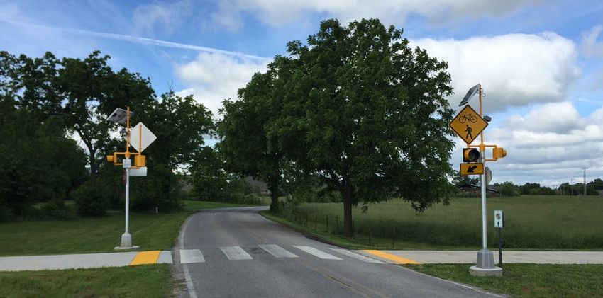
BICYCLE DETECTION | 19Microwave/Radar Overview
Controller Compatibility High Microwave radar devices are used in several different traffic
Installation Complexity Moderate to High applications. In general, these devices detect traffic by
Functionality Presence (Yes) transmitting microwave energy toward the roadway and
Counts (Yes) measure the return signal reflected from vehicles on the
Directionality (Yes) approach. While CW (Continuous Wave) Doppler radar can
Distinguish Multiple Bikes (No)
only detect flow and speed, FMCW (Frequency Modulated
Durability Good
Continuous Wave) radar can also act as a presence
Ideal Applications Where advanced detection is
detector. As such, this discussion will focus on microwave
desired or where the ability to
FMCW radar detection systems. At an intersection, a
differentiate direction of travel is
important. microwave radar detection system typically consists of
one or more FMCW radar devices and a cabinet interface
module to process the feedback data from the devices and
Strengths
communicate with the traffic signal controller. In terms of
• Used for both vehicles and bikes bicycle detection, microwave radar detection systems need
to have bicyclist approaches within the FMCW radar device’s
• Provides actuation regardless of metal content in bike field of view.
• Can provide bike counts from dedicated or shared-use
lanes (with specific equipment configuration) Common Applications
• Can perform advanced and stop bar detection in a single Microwave radar detection is a good option for signalized
unit intersections at which the installation of loops would not
be practical and at which the installation of other common
• Does not require pavement disruption
forms of detection, such as video, are determined to be
• Can be easily reconfigured to adapt to changes in the problematic due to weather, low light, occlusion, or other
intersection factors. The range of some microwave radar detection
devices allows for them to be used as both presence and
• Can distinguish between bikes and other vehicles
advance detection, making them a cost-effective option
• Troubleshooting can typically occur outside of roadway for some intersections. Many microwave radar detection
limits devices are capable of collecting counts, speed, distance,
and classification data, with advances in detection software
• Typically insensitive to inclement weather, glare, or low
providing the ability to differentiate between bicycles and
light conditions
other vehicles. Signal timing modifications such as time
extensions can be added when bicyclists are detected.
Weaknesses
At signalized intersections, these devices provide the most
• Can have issues when placed in close proximity to large
benefit when mounted to traffic signal poles or mast arms
steel structures (e.g., steel bridges)
such that the device is high enough to detect multiple
• Can have issues with overhead conductors within a detection zones. As such, microwave radar systems
microwave radar device’s field of view can vary in their cost-effectiveness due to the need to
provide additional mounting structures necessary for
• Proper operation relies on proper field interpretation and
roadway geometry or the lack of existing tall traffic signal
set-up of detection zones
infrastructure or signal mast arms. When exploring the
• Complexity associated with communication from multiple potential use of this detection at a particular intersection,
detection zones to central unit can impact reliability designers should consider the desired functionality of the
detection system and the required placement of microwave
• As compared to video, more difficult to confirm aim of
radar devices. Because these devices provide a 90-degree
detection optics and, thereby, troubleshoot
20 | ALTA PLANNING + DESIGNThis microwave detector in along the Razorback Greenway in Northwest Arkansas activates a warning beacon when a trail user (pedestrian or
bicyclist) is approaching the roadway crossing.
field-of-view, they have some flexibility to be mounted Installation Considerations
outside of the roadway limits. The functionality of these
devices, however, can be affected by the presence of large Any installation using a signal mast would require lane
steel structures (such as steel trusses associated with closure for operation of a bucket truck, with those
bridges) or overhead conductors. Therefore, in-person installations to the mast arms likely requiring a greater
reviews are strongly recommended to determine the disturbance to vehicular traffic. These devices are
suitability of a particular site for the implementation of sometimes mounted to luminaire mast arms to provide
a microwave radar detection system. It typically can be an even greater mounting height. For bicycle-specific
helpful to confirm the feasibility of microwave radar device detectors, they do not need to be mounted as high and
placement with a manufacturer’s representative. can be attached to poles. Manufacturers typically provide
recommended mounting heights for the radar devices,
Microwave radar detection systems can also be used at based on the device’s offset from the first detection lane.
bicycle-specific approaches or shared-use path mid-block Many manufacturers recommend mounting the devices as
crossings. In these cases, the microwave radar devices close to perpendicular to the flow of traffic as possible. For
can offer passive actuation of signalized crossings for both this reason, these devices are commonly mounted on the
bicyclists and pedestrians. Detection of these movements vertical portion of the nearside traffic signal post, rather
does not typically require the greater mounting heights than the far side mast arm, as is commonly specified with
that are advantageous for vehicular movements. As such, video detection cameras. The radar devices typically are
in these types of applications, cameras can be mounted to mounted with a horizontal extension bracket that allows for
pedestal signal or beacon posts, as long as security of the the device to be tilted and aimed toward the center of the
radar equipment is ensured. These detection systems have detection area.
also been “retrofit“ installed for similar situations in which
the push button use compliance rate was found to not be Typical microwave radar detection systems are capable
satisfactory. of connecting four sensors to one cabinet interface
module. Systems vary, but most microwave radar sensors
are capable of supporting up to eight detection zones.
Communication with and data transmission between
BICYCLE DETECTION | 21the sensors and the cabinet interface module is typically Use as Counter
achieved by running cable either aerially or through the
traffic signal infrastructure and the underground pull box/ Microwave sensors are a popular technology used to detect
conduit runs used for traffic signal conductor cables. The and count bicyclists and pedestrians. There are many
sensor units generally require low power consumption, and commercially available products that have a variety of
can draw power either through a wired connection to a strengths. Some are designed specifically for shared-use
power source, or from properly-rated solar panels. paths, while some may also work in bike lanes or shared
lanes. Depending on the product, the device may be able
to count bicyclists and pedestrians separately, together, or
be configured to omit one or the other. Devices used solely
as counters are typically mounted at low height (two to five
feet above ground level). Equipment should be secured so
that it is not vandalized or removed.
Data can be collected continuously and downloaded via
a physical connection or wirelessly through the internet
using a SIM card connected to the cellular network. Alta
has a companion white paper entitled “Innovation in
Bicycle and Pedestrian Counts” available on our website
(www.altago.com).
This microwave detector in Huntsville, AL, calls the bicycle signal
only for approaching bicyclists who are within the separated
bike lane. Microwave detectors can determine if the bicyclist is
approaching or moving away from the intersection to avoid false
calls.
KEY TIPS
Radar can be set to only detect above a certain
approach speed which could be used to distinguish
between bicyclists and pedestrians. Studies conducted
in California found that high speed bicyclists might
sometimes be classified as vehicles. Similarly, groups of
bicyclists were sometimes classified as vehicles. This microwave automated counter counts the volume of
pedestrians and bicyclists accessing this rail station in Oakland, CA
Occlusion can occur if placed incorrectly to detect
bicyclists. Be wary of placing the unit where a heavy
vehicle may block the units ability to detect a bicyclist.
22 | ALTA PLANNING + DESIGNADDITIONAL TECHNICAL DETAIL Communication equipment and software associated with
microwave radar detection systems can also be subject
Design and Product Specification Considerations to Telecommunication Industry Association (TIA) 232
standards and Federal Communications Commission (FCC)
Microwave radar detection systems typically are equipped
certification requirements. Some agencies have considered
with management software used to correct the sensor
these industry standards in developing approved product
installation and fine-tune sensor alignment. These
lists for these systems, and, as such, manufacture of these
software applications are typically run through a field
systems has become fairly standardized. However, it is
computer that interfaces with the cabinet interface module
important to consider that some approved product lists
(detection card). Cabinet interface modules associated
may have been developed without consideration of active
with microwave radar detection systems are compatible
transportation needs. As such, designers should verify that
with standard NEMA cabinets and controllers. Many
the capabilities and functionality of an agency’s approved
maintenance and adjustment activities required for an
products are consistent with the goals of a given project,
active infrared detection system can take place from within
particularly with respect to a unit’s ability to distinguish
the controller cabinet using the computer interface.
between bikes and other vehicles, and the ability to provide
Additional Standards bike counts.
Various industry standards have been developed for the
purpose of specifying microwave radar detection systems.
Such industry standards include, but are not limited to,
those associated with:
• National Transportation Communication for ITS Protocol
(NTCIP)
• National Electrical Manufacturer Association (NEMA)
• National Electric Safety Code (NESC)
• National Fire Protection Association (NFPA) 70 – National
Electric Code
• National Fire Protection Association (NFPA) 780 –
Standard for the Installation of Lightning Protection
Systems
• Underwriter Laboratories (UL) Standards – 96 & 96A
Lightning Protection
• Underwriter Laboratories (UL) Standards – 1449 Surge
Protective Devices
BICYCLE DETECTION | 23Video • Accuracy can be affected by vehicle/road contrast and
other visual obstructions, such as dirt, salt, cobwebs, or
Controller Compatibility Low to Moderate span wires and aerial utilities within the field of view
Installation Complexity Moderate to High
Functionality Presence (Yes)
• Detection zones can pick up false activations from
Counts (Yes) adjacent lanes if configured improperly
Directionality (Yes)
• Some communities can be sensitive to privacy concerns
Distinguish Multiple Bikes (Yes)
Durability Good
Overview
Ideal Applications Most bicycle oriented scenarios
In modern traffic management applications, video
detection systems use video image processing to determine
Strengths
when to place signal calls. A video detection system
• Used for both vehicles and bicyclists typically consists of one or more cameras, a microprocessor
to process the imagery, and software to interpret the traffic
• Provides actuation regardless of metal content in bike flow data and communicate with the traffic signal controller.
• Can distinguish between bikes and other vehicles In general, video detection systems can determine vehicle
arrivals by analyzing successive video frames. Modern video
• Can supplement other forms of detection in use at an detection systems can also extract a significant amount of
intersection data through the associated video image processor (VIP).
• Can distinguish multiple bicycles on an approach The VIP often consists of a microprocessor on a detection
card/board that is compatible with standard NEMA
• Can be configured to count bicyclists in dedicated or cabinets and controllers. In terms of bicycle detection,
shared-use lanes (though accuracy has historically not video detection systems feature cameras aimed at bicyclist
been consistent) approaches and software calibrated to detect the smaller
• Can be easily reconfigured to adapt to changes in the vehicle size associated with bicyclists.
intersection
Common Applications
• Does not require work within the roadway limits to
install; however, camera installation may require Video detection is a good option for signalized intersections
temporary lane closures at which the installation of loops would not be practical
due to the existing pavement condition or structural
• Troubleshooting can typically occur outside of roadway
composition, or due to right-of-way or jurisdictional issues.
limits
Many agencies are moving completely to video or thermal
detection for all intersections, with many establishing Traffic
Weaknesses
Management Centers (TMCs) that can monitor the entire
• Initial installation costs can be relatively high network remotely. Video detection systems are typically
mounted to traffic signal poles, mast arms, and luminaries
• Complexity associated with communication from
such that the camera lens has a suitable vantage point to
multiple video zones to central unit can impact reliability
clearly observe as many detection zones as possible. In
• Proper operation relies on proper field interpretation some instances, it can be helpful to confirm the feasibility
and set-up of detection zones of potential camera placement with a manufacturer’s
representative.
• Accuracy can be affected by weather conditions,
including rain, snow, fog, sun glare, shadows, and day-to- In shared lane contexts, bicyclists can be distinguished
night transitions from vehicles with recent advances in detection
software. Separate detection zones can also be set up for
24 | ALTA PLANNING + DESIGNThis image represents a still taken from a video camera showing the detection zones in red (credit: NACTO)
bicycle-only facilities. In either case, counts or signal timing Installation Considerations
modifications such as time extensions can be added when
bicyclists are detected. Camera equipment associated with video detection
systems is typically mounted on mast arms over the
For bicycle-specific approaches, video cameras can be roadway, and, therefore, requires lane closure for operation
mounted lower. As such, in these types of applications, of a bucket truck. These cameras are often mounted to a
cameras can be mounted to pedestal signal or beacon vertical extension bracket that positions the camera above
posts, as long as security of the camera equipment is the mast arm to maximize mounting height. The cameras
assured. Video detection systems have been “retrofit“ are sometimes mounted to luminaire mast arms in order
installed for similar situations in which the push button use to provide an even greater mounting height. For vehicular
compliance rate was found to not be satisfactory. traffic approaches, the FHWA recommends a minimum
camera mounting height of 40 feet above the detection
In general, modern video detection systems offer a great
area if the camera is centered over the roadway. Higher
deal of flexibility in how they interpret vehicle arrivals and
mounting heights (on the order of 50 feet or greater) are
how they interface with traffic signal controller software.
recommended if the camera is located at the side of a
Advances in camera technology have significantly improved
roadway. The camera mounting height should increase
upon issues with reliability associated with older camera
as the camera is moved further from the road edge to
models. Similarly, software is updated regularly and can
achieve optimal performance. The camera location should
improve accuracy and functionality if kept current. Agencies
minimize occlusion of down-lane and cross-lane vehicles.
should ensure that video detection systems in use and
Down-lane occlusion refers to a vehicle blocked from view
listed as qualified products for installation are consistent
by a tall vehicle in front of it. Cross-lane occlusion refers
with the expected capabilities.
to a vehicle blocked from view by a tall vehicle in a lane
BICYCLE DETECTION | 25closer to the camera. Due to this need, specific camera
locations typically must be determined in the field while
simultaneously viewing the video feedback.
Camera locations should typically be chosen such that
vibration and motion is minimized. However, some modern
models have the ability to stabilize imagery and are
designed for span wire mounting if more stable mounting
cannot be achieved. In general, cameras often require a
downward tilt or the installation of a sunshield to prevent
glare from the horizon. Camera locations must also attempt
to minimize glare from headlights and reflections from the
pavement, which can sometimes be mitigated by the use
of a longer focal lens length. Infrared (or thermal) cameras,
covered in the next section, overcome many of these
disadvantages.
This camera in Missouri has been raised in elevation to obtain a
better view of the intersection and its detection zones
KEY TIPS
Video detection can be very flexible in changing
intersection configurations.
Single camera systems that operate with a “fish eye”
view of the intersection may not be as accurate for
bicycle detection as multiple camera systems. The
City of Austin has added supplemental bicycle specific
video cameras for bike approaches, which adds
expense.
Many existing video-based detection systems can
have the ability to detect and count bicyclists added
for low or no cost through manufacturer software and Video detection is being used at this protected intersection in
firmware updates. Fremont, CA
26 | ALTA PLANNING + DESIGNADDITIONAL TECHNICAL DETAIL
Further Installation Guidance Calibration
The focal length of the camera lens is dependent on the Calibration of the image area requires that several pieces of
mounting height of the camera, the local topography, data be provided to the VIP. This typically involves defining
distance to the nearest detection area, and the width of the lens focal length, the CD array size, the dimension of
the detection area. The resulting horizontal and vertical the image area (along-lane and cross-lane dimensions), the
fields of view correspond to a required focal length. If the number of lanes, distance between two defined points in
required focal length does not correspond to a standard the image, the external communication rate, the camera
lens, then the mounting height or one of the detection output voltage, date, time of day, and traffic flow direction.
area parameters is varied in order to allow specification of Calibration can also require inputting the camera’s
a standard lens having a horizontal focal length above or horizontal and vertical angle, camera height, camera
below that of the initial calculation. Many modern cameras offset from the traffic flow, the typical traffic flow rate,
associated with video detection systems have variable focal lane occupancy, speed, headway, vehicle length, distance
length lenses available, so that a specific lens does not have to detection zone, and length of detection zone. The
to be identified in advance. microprocessor associated with the VIP sends processed
presence data received from the cameras directly to the
Upon mounting the camera, transmission of the video
traffic signal controller via cable-connected outputs.
imagery to the VIP must be accomplished. Although
wireless video detection systems are available, this is The majority of maintenance and adjustments required for
typically achieved by running cable for power, control, and a video detection system can take place from within the
data transmission to and from each camera. Like push controller cabinet using a computer interface. However,
buttons or other actuation devices, the wireless systems maintenance of video detection systems can occasionally
are generally viewed as less reliable. Communication with require lane closures to address storm damage or general
the VIP (located in the controller cabinet) can be achieved “wear and tear” to cameras mounted on mast arms, or to
by running cable aerially or through the traffic signal clean the associated lenses.
infrastructure and the underground pull box/conduit runs
used for traffic signal conductor cables. Once video imagery
is transmitted to the VIP, operating parameters should
be established, detection zones on the roadway should
be defined, and the image area calibrated. Most video
detection systems are provided with setup and calibration
software that can be operated on a personal computer that
interfaces with the VIP. Detection zones can be calibrated
to gather vehicle presence, counts, speed, lane occupancy,
and vehicle length classification data. VIP devices also
typically provide the ability to program special operational
conditions for connecting detection zone outputs, which
can be useful in ensuring more accurate actuation and
vehicle counts. The detection zones are typically drawn
onto the camera’s field of view using the computer monitor
interface. Multiple detection zones can be drawn within the
field of view of each camera.
BICYCLE DETECTION | 27Infrared Overview
Controller Compatibility Low to Moderate
In terms of modern vehicular detection at intersections,
Installation Complexity Moderate to High
infrared technology is commonly deployed in conjunction
Functionality Presence (Yes)
Counts (Yes)
with the video detection systems discussed in the previous
Directionality (Yes) section. Infrared video detection systems, also referred to
Distinguish Multiple Bikes (Yes) as thermal video detection systems, are an increasingly
Durability Good popular method of addressing common issues associated
Ideal Applications Most bicycle oriented scenarios with traditional video detection systems, such as weather
or time-of-day glare. In general, the sensors associated with
these detection systems use thermal imaging to detect
Strengths oncoming vehicles. Because these systems rely on the heat
signature associated with vehicles or bicyclists, they are
• Used for both vehicles and bicyclists unaffected by line-of-sight issues associated with traditional
video cameras. Infrared detection systems typically consist
• Does not have weaknesses of video detection as it can
of one or more thermal cameras, a microprocessor to
see through fog, snow, and direct sunlight or shadow
process the thermal imagery, and software to interpret the
• Provides actuation regardless of metal content in bike traffic flow data and communicate with the traffic signal
controller. These systems are typically able to extract a
• Can distinguish between bikes and other vehicles
significant amount of data from the thermal imagery.
• Can supplement other forms of detection in use at an
intersection Common Applications
• Can distinguish multiple bicycles on an approach Infrared detection systems are commonly installed for
• Can be configured to count bicyclists from dedicated or intersections at which existing video detection systems
shared-use lanes (though accuracy has historically not have proven to be problematic due to various issues. Video
been consistent) detection systems can commonly be affected by weather,
time-of-day glare, or other visual obstructions. With the
• Can be easily reconfigured to adapt to changes in the use of infrared video detection systems becoming more
intersection common, some agencies are anticipating potential issues
• Does not require work within the roadway limits to with traditional video detection systems and opting for
install; however, camera installation may require specification of thermal cameras with the construction of
temporary lane closures new traffic signals. Modern manufacturers of traditional
video detection systems are commonly making available
• Troubleshooting can typically occur outside of roadway an infrared video detection option, or even dual camera
limits systems which feature both technologies. In many
instances, an in-person review with a manufacturer’s
Weaknesses representative can be helpful to confirm whether an
• Initial installation costs can be relatively high infrared detection system would be a cost-effective
solution to address potential issues with a traditional video
• Complexity associated with communication from detection system.
multiple video zones to central unit can impact reliability
Infrared detection systems can also be applied at
• Proper operation relies on proper field interpretation shared-use path mid-block crossings or other special
and set-up of detection zones intersections in a similar manner as discussed for push
• Detection zones can pick up false activations from button actuation. In these applications, thermal cameras
adjacent lanes if configured improperly can be mounted on nearby traffic signal pedestal posts.
These can be installed for locations in which the push
28 | ALTA PLANNING + DESIGNYou can also read