Mobility Enhanced Spectrum Analyzer - User Manual - Research Electronics International, LLC - Research Electronics ...
←
→
Page content transcription
If your browser does not render page correctly, please read the page content below
Mobility Enhanced Spectrum Analyzer
            User Manual

               Research Electronics International, LLC
                 455 Security Drive, Cookeville, TN 38506 U.S.A.
                  (800) 824-3190 (US Only) • +1 931-537-6032
                                www.reiusa.net
            © Copyright Research Electronics International LLC.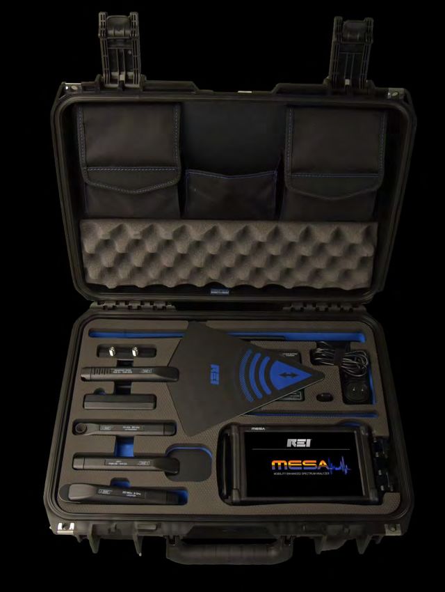
1

MESA® DELUXE CASE CONTENTS

                                                               18
                                17

                                                 16
                                                                        19

                                                          11
                           10                9
                                                               12      13
                                     8                                 14
                           7                                    15
                           6                          1

                       4             5
                                                  2
                                         3

                                                                11. Whip Antenna*
    1. MESA Unit*
    2. (2) Lithium Ion Batteries*                               12. Battery Charger
       - Stored under unit                                          - Partially stored under Down Converter
    3. Visible Light/Infrared Probe                             13. Power Plug with International adapters
       - Stored under Locator Probe                             14. GPS Adapter
    4. Locator Probe                                            15. Fixed Whip Antenna*
    5. VLF Loop*                                                16. Headphones (2)*
    6. Ultrasonic Probe                                                - In pocket
    7. Audio Transformer                                        17. (2) Powered QMA antenna cables
                                                                    (2) Non-Powered QMA cables*
    8. Directional Antenna
       - Stored under Down Converter                            18. Acoustic Leakage Detector
    9. Down Converter Antenna                                   19. Accessory Cables, screen cleaner*,
    10 Multi-Carrier Probe (MCP)                                       data storage thumb-drive

                                                                    *Item included in the MESA Basic, but case location
                                                                    may vary.
                                                          2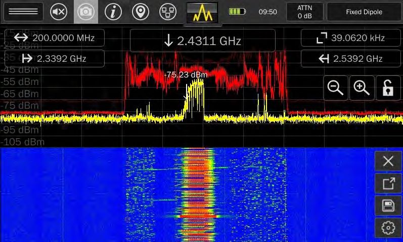
This document is intended to provide guidance and instruction on using the MESA – Mobility Enhanced
Spectrum Analyzer for finding hidden electronic devices.

This manual contains proprietary information intended solely for use with the MESA product.

The overall effectiveness of this product, and of any surveillance countermeasure, is dependent on the
threat level and the user’s ability to properly utilize the appropriate equipment.

REI offers the world’s largest commercially available Technical Security training facility. Training courses
include classroom instruction and hands-on exercises where students perform sweep exercises in “live”
environments utilizing target-rich project rooms. The progressive course curriculum is designed for the
beginner or the seasoned Technical Security Technician.

Regularly scheduled courses are taught monthly; visit REI’s website (www.reiusa.net) or contact REI
(sales@reiusa.net) for training dates.
                                                      3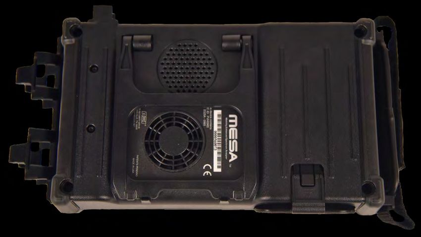
Revision 1.5

                 © COPYRIGHT RESEARCH ELECTRONICS INTERNATIONAL

REI products are designed and intended for legal commercial applications. However, because laws
and regulations vary from state to state and country to country, it is the sole responsibility of the
purchaser and user/operator to check and comply with all applicable laws and regulations for the
possession and operation of this equipment before and after making a purchase.

Information contained in this manual including product operation and specifications is subject to
change without notice.

Any product or brand names contained in this manual are used only for identification purposes and are
trademarks or registered trademarks of their respective holders.

This equipment generates, uses and can radiate radio frequency energy and, if not installed and used
in accordance with the instructions, may cause harmful interference to radio communications.
However, there is no guarantee that interference will not occur in a particular installation. If this
equipment does cause harmful interference to radio or television reception, which can be determined
by turning the equipment off and on, the user is encouraged to try to correct the interference by one
or more of the following measures:

    -    Reorient or relocate the receiving antenna.
    -    Increase the separation between the equipment and receiver.
    -    Connect the equipment into an outlet on a circuit different from that to which the receiver is
         connected.
    -    Consult the dealer or an experienced radio/TV technician for help.

The Serial Number of each MESA is located on the back of the unit. Please record this number and
refer to it whenever you contact your dealer or Research Electronics International concerning this
product. Note: Removal or alteration of the serial number automatically voids all warranties of this
product.

SERIAL NUMBER:

                                               Research Electronics International, LLC
                                                       455 Security Drive, Cookeville, TN 38506
                                                           U.S.A. (800) 824-3190 (US Only)
                                                                   +1 931-537-6032
                                                                    www.reiusa.net

                                                      4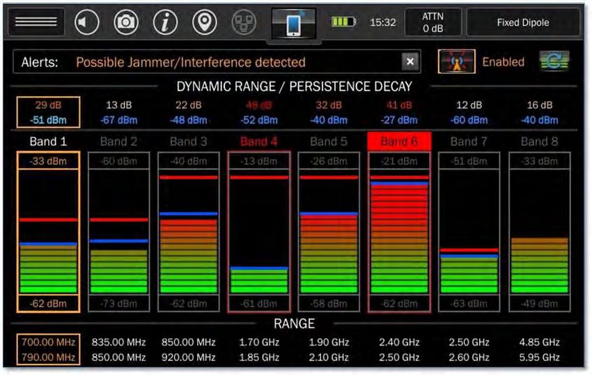
Contents
     Warnings and Cautions ........................................................................................................................... 7
Equipment Description ................................................................................................................................. 9
   MESA® Unit ................................................................................................................................................ 9
Cleaning and Maintenance ......................................................................................................................... 11
Operation .................................................................................................................................................... 11
   Setup & Use ............................................................................................................................................ 11
   Inserting the Battery ............................................................................................................................... 12
   Power Control and Charging ................................................................................................................... 13
   MESA® Packages ...................................................................................................................................... 14
   Probes, Antennas, and Accessories ........................................................................................................ 14
   Audio Transformer Batteries .................................................................................................................. 19
   Connecting the Antenna & Probes ......................................................................................................... 20
       Powered Connector Cable (only included with the MESA Deluxe) .................................................... 20
       Manual Selection of Probes ................................................................................................................ 21
   Display ..................................................................................................................................................... 22
   Status Bar ................................................................................................................................................ 24
       Mode Settings Menu........................................................................................................................... 24
       Volume Control ................................................................................................................................... 24
       Screenshot .......................................................................................................................................... 24
       Help ..................................................................................................................................................... 24
       GPS Location ....................................................................................................................................... 25
       Network Status and Setup .................................................................................................................. 27
       Battery Life .......................................................................................................................................... 27
       Setting the Time Zone, Date, and Time .............................................................................................. 28
       Attenuator/PreAmp ............................................................................................................................ 29
   Modes ..................................................................................................................................................... 29
       Mode Menu ........................................................................................................................................ 29
       Spectrum Mode .................................................................................................................................. 29
       SmartBars™ ......................................................................................................................................... 42
       Mobile Bands ...................................................................................................................................... 51
       Wi-Fi & Bluetooth ............................................................................................................................... 60

                                                                                5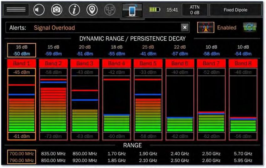
Additional Features ................................................................................................................................. 66
   Signal List Window .............................................................................................................................. 66
   Image Viewer & Audio Player ............................................................................................................. 73
   Locked Monitor Mode ........................................................................................................................ 75
   Network Configuration ....................................................................................................................... 76
   VNC Operation .................................................................................................................................... 79
   Down Converter Directional Antenna Operation ............................................................................... 83
   Updating Software .............................................................................................................................. 84
System Menu .......................................................................................................................................... 85
   Brightness............................................................................................................................................ 85
   Version ................................................................................................................................................ 85
   Image Viewer ...................................................................................................................................... 85
   Audio Player ........................................................................................................................................ 85
   Network Settings................................................................................................................................. 85
   Prefix Settings ..................................................................................................................................... 85
   ITU Region ........................................................................................................................................... 86
   Power Down Cache Setting ................................................................................................................. 86
   Snap to Peak Setting ........................................................................................................................... 86
   Factory Reset ...................................................................................................................................... 86
Specifications .......................................................................................................................................... 87
   Receiver............................................................................................................................................... 87
   Features .............................................................................................................................................. 87
   Power .................................................................................................................................................. 87
   Mechanical .......................................................................................................................................... 87
   Environmental ..................................................................................................................................... 88

                                                                           6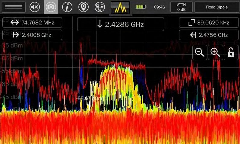
Warnings and Cautions
MESA
CAUTION: Any changes or modifications not expressly approved by REI could void the user’s
authority to operate the equipment.
The MESA is for professional use only.
For your safety do not use the MESA if:
o The MESA cables or its plugs become frayed or otherwise damaged.
o The MESA housing is cracked or otherwise damaged.
o You suspect that the unit requires servicing.
Only use REI approved power sources, batteries, chargers, and accessories. The supplied power
supply is REI #R-00021 (Front Power #A481-1503000I). The supplied battery pack is REI #R-
00001 (RRC Power Solutions #RRC-2040), a rechargeable Lithium-Ion battery.
The slots in the housing of the unit are vents and are part of the ventilation system. Do not
block these vents during the operation of the unit.
The fan that is visible from the back of the unit is part of the ventilation system. The fan does
not operate constantly but only as needed to reduce the internal temperature of the unit. Do
not forcibly stop or disrupt the operation of the fan.
Equipment is to be serviced by the manufacturer only. There are no serviceable parts inside.
Contact your dealer or Research Electronics International, LLC for repairs. Opening the unit will
void the warranty.
If the equipment is used in a manner not specified in this manual, the protection of the
equipment may be impaired.
For your safety do not use the AC power adapter or the included USB cable if:
o The cable becomes frayed or otherwise damaged.
o The power adapter plugs are damaged.
o The power adapter housing is cracked or otherwise damaged.
o The power adapter is exposed to rain, liquid, or excessive moisture.
Lithium-Ion Batteries
CAUTION: RISK OF EXPLOSION IF BATTERY IS REPLACED BY AN INCORRECT TYPE. DISPOSE OF
USED BATTERIES ACCORDING TO THE INSTRUCTIONS.
For your safety do not use any MESA battery if:
o The battery case is cracked or otherwise damaged.
o The battery is excessively hot or warm for any reason.
Avoid shorting the battery, immersing in water, or exposing to fire. Also, avoid excessive
physical shock or vibration.
Only use the specified REI battery chargers or products to charge REI batteries
There are no serviceable parts inside the battery. Contact your dealer or Research Electronics
International, LLC for repairs. Opening or puncturing the unit can be dangerous and may result
in injury.
7
Using the Lithium-Ion batteries in a manner not specified by this user’s guide may override the
equipment’s built-in protection mechanisms.
Keep out of the reach of children.
Dispose of Lithium-Ion batteries in accordance with local regulations.
8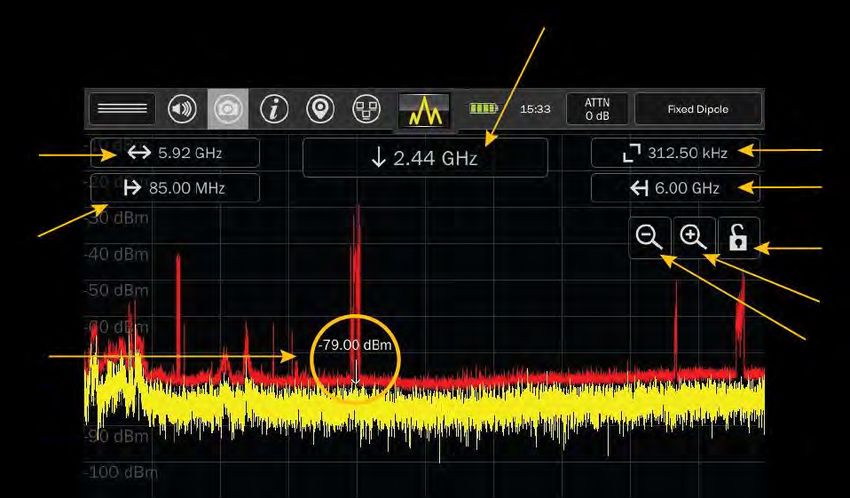
Equipment Description
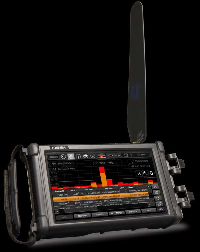
MESA® Unit
1. Touch Screen Display - user interface for MESA
2. Battery Door (on the bottom of the unit) - conceals battery compartment
3. Speaker (on the back of the unit) - used to output audio from the unit
4. Fan - used for cooling unit
95. Power Button - turns the unit off and on
6. Power input - for AC adapter (only use REI supplied AC Adapter)
7. Ethernet connector - Used to access the MESA unit remotely using VNC (Virtual Network
Computing) 3rd party software
8. Audio Input - for connecting the Acoustic Leakage Detector and the Audio Transformer to test
for the presence of audio. The Acoustic Leakage Detector and the Audio Transformer are
included with the MESA Deluxe package from REI.
9. Headphone Jack - for connection of headphones to monitor audio from the unit.
10. USB Port - for saving files from the MESA and for possible future use as probe/accessory control.
Note: Only a single USB thumb drive at a time is supported. Even if a USB hub is connected, only
a single storage USB drive is supported
11. QMA Connector (RF Input) - for connecting the included REI antennas or other RF antennas
12. Hand Strap - to help support holding the MESA unit
13. Probe Grip - for clipping probe handles to the MESA unit
10Cleaning and Maintenance
To prevent electrical shock, unplug the MESA from AC power and remove the battery.
For the display, wipe gently with a soft cloth. A small amount of ethyl alcohol or a neutral detergent
may be used. Please exercise caution when handling hazardous chemicals.
For general cleaning and decontamination, use a damp cloth with a mild soap solution. For more
thorough decontamination, a small amount of 70% isopropyl alcohol could be used.
Operation
The MESA has been designed for quick and easy deployment. Depending on your application some
adjustments to the default setting may be needed.
The MESA is a swept spectrum analyzer featuring a bar graph representation of the spectrum and is
used to locate transmitters by monitoring the RF signal strength. When searching for unknown
transmitters, it is advised to remove or disable any known transmitters from the target sweep area (i.e.
unplug, turn off, or remove any wireless transmitting devices including Wi-Fi and Bluetooth devices,
laptops/PCs, mobile phones, wireless transmitting devices, etc.), as any transmitting devices can hinder
detection of unknown transmitters.
Setup & Use
A hand strap is provided on the side of the MESA. When using the product in a hand-held manner, hold
the unit securely by sliding your hand under the hand strap and gripping the side of the unit
A built-in stand is provided to allow for hands-free support on a table-top or surface. To release the
stand, pull the bottom of the stand away from the MESA unit until it releases from the built-in clips.
Continue extending the stand to its furthest position. Place the MESA on a sturdy, level surface resting
on its back edge and the stand.
11Inserting the Battery
The battery-operated MESA provides for truly hand-held, portable spectrum analysis. To insert a
battery:
1. Locate the battery door latch on the rear of the MESA near the bottom edge of the unit.
2. Supporting the MESA unit with both hands, place a thumb on the battery door latch.
3. Simultaneously press on the battery door latch while sliding it away from the unit.
4. Once the battery door is lifted, place your thumb under the edge of it and open it up fully.
5. Slide the battery into the battery slot observing proper contact alignment. Press firmly until the
battery is fully seated.
6. Close the battery door until the edge lines up with the lip on the battery door latch. Then place
a finger on both the battery door and the latch and press them close together.
12Power Control and Charging
To turn on your MESA unit, ensure that a charged battery is in the unit or connect the supplied AC
adapter and press and hold the power button (see page 9) until it begins flashing. During operation, to
turn off your MESA unit, press and hold the power button until the "Power Off" graphic appears on the
screen.
Press and hold the power button 8 seconds or more to perform a firmware reset. This method should
only be used if the unit has locked up and the normal shutdown method is not functioning.
The MESA unit has a built-in battery charger. The MESA
unit will automatically begin charging an inserted battery
if the AC adapter is connected. Plug the AC Wall adapter
into the power outlet and then plug the connector into
the port labeled "Power" on the top of the MESA.
Note: If the operating temperature of the unit is elevated,
above 37 degrees C, the battery charging will not begin
until the temperature drops below 37 degrees C.
Note: It is recommended that the MESA battery be
recharged regularly during extended periods of storage (3
months or more) to prevent damage to the battery.
Additionally, when storing the MESA for long periods (1
month or more), it is recommended that the battery be
removed from the unit and placed in the storage
compartment in the case. Storing the MESA with the
battery in the unit can deplete it more rapidly, potentially
shortening the life of the battery.
13MESA® Packages
The MESA is available in two packages (Basic and Deluxe) with varying probes, antennas, and
accessories. Below is a chart showing which probes, antennas, and accessories are included in each
package (note that this is subject to change). Additional information can be found in the Probes,
Antennas, and Accessories section on the following pages.
MESA PACKAGES
BSC DLX
Fixed Dipole Antenna (85 MHz - 6 GHz) X X
Whip Antenna (30 MHz - 6 GHz) X X
MCP Multi-Carrier Probe (100 kHz - 60 MHz, 5 MHz - 2 GHz) X X
VLF Loop Antenna (10 kHz - 30 MHz) X X
Batteries (2) X X
Down Converter Antenna (500 MHz - 12 GHz) X
Probes/Accessories
Directional Antenna (70 MHz - 500 MHz) X
Locator Probe (20 MHz - 6 GHz) X
Visible Light / Infrared Probe (10 kHz - 50 MHz) X
Ultrasonic Probe (15 kHz - 80 kHz) X
Audio Transformer (300 Hz - 20 kHz) X
Acoustic Leakage Detector (300 Hz - 20 kHz) X
GPS Adapter X
Probes, Antennas, and Accessories
Fixed Dipole Antenna (85 MHz - 6 GHz)
The Fixed Dipole Antenna is a versatile, omnidirectional antenna that connects directly to the MESA unit
without the need for cables.
14Whip Antenna (30 MHz - 6 GHz)
The Whip / Dipole is a versatile, omnidirectional, near-field probe used for locating RF transmitters up to
6 GHz.
MCP Multi-Carrier Probe (100 kHz - 60 MHz, 5 MHz - 2 GHz)
The MCP (Multi-Carrier Probe) extends the functionality of the MESA with the addition of different
connectors to allow for the analysis of suspicious signals: an AC power plug and coaxial connectors.
To use the AC power plug, the "MCP (AC Carrier Current)" option must be selected in the Input Info
window (see page 21). To use the coaxial connectors, the "MCP (Coax)" option must be selected in the
Input Info window.
The MCP can be used to test for carrier current signals on any pair of conductors less than 250 volts.
Before testing an unidentified pair of power conductors, a voltmeter should be used to measure the
voltage across the conductors. If this voltage exceeds 250 volts, do not test with the Carrier Current
Probe. Two power plugs are included for connection to US-style or Euro-style outlets. The included
alligator clip cable assembly should only be used on 50V or less. Measurements can be made with three
different pair configurations using the switch on the front of the carrier current probe: Hot/Neutral,
Neutral/Ground, and Hot/Ground.
Due to power line noise and the broad frequency range that MESA searches, every outlet in an area
should be inspected.
The coaxial connectors on the MCP can be used to test for suspicious signals on coaxial cables. The MCP
can be used to make both in-line measurements and single-ended measurements. For in-line
measurements, connect one side to the Coax Input. The same signal will be output at the Coax Output
connector. For single-ended measurements, connect to the Coax Input connector.
15VLF Loop Antenna (10 kHz - 30 MHz)
The VLF Loop Antenna is an omnidirectional antenna used for locating low-frequency signals below 30
MHz.
Down Converter Directional Antenna (500 MHz - 12 GHz)
The Down Converter Antenna is a directional antenna that operates in 2 user-selectable bands:
Band 1: 500 MHz - 6 GHz
Band 2: 6 GHz - 12 GHz
When using Band 2, the Down Converter Antenna converts signals occurring above the standard 6 GHz
threshold so they can be detected and displayed on the MESA. For details on operation, see page83 .
Directional Antenna (70 MHz - 500 MHz)
This flag-shaped antenna provides directional coverage for lower frequency signal detection. It is a
powered probe and must be used with one of the powered connector cables (see page 20).
16Locator Probe (20 MHz - 6 GHz)
The Locator Probe is omnidirectional and is attenuated for use in high RF environments and for locating
an RF signal within a few inches.
Visible Light / Infrared Probe (10 kHz - 50 MHz)
The Visible Light / Infrared Probe can be used for detecting the presence of IR or visible light. This probe
is a powered probe and must be used with one of the powered connector cables (see page 20).
Ultrasonic Probe (15 kHz - 80 kHz)
The ultrasonic probe detects sound waves operating above the upper limit of human hearing
capabilities. The ultrasonic probe is a powered probe and must be used with one of the powered
connector cables (see page 20).
17Audio Transformer (300 Hz - 20 kHz)
The Audio Transformer is a balanced audio coupler to provide electrical isolation for audio testing. A 3.5
mm stereo to 3.5 mm stereo cable is included with the MESA to connect the audio transformer to the
MESA. Two push buttons provide a positive and negative bias voltage to the two banana jacks on the
audio transformer. The control knob on the audio transformer adjusts the level of the applied bias
voltage from 0 to 22 volts. An included set of banana jack test leads with bed-of-nail alligator clips allow
the audio transformer to be used on 66 blocks or other wires.
Acoustic Leakage Detector (ALD) (300 Hz - 20 kHz)
With the Acoustic Leakage Detector, the operator can determine the vulnerability of acoustic leakage by
placing the probe against structural objects such as walls or windows. The Acoustic Leakage Detector
connects to the Audio Input on the MESA.
18GPS Adapter
The GPS Adapter is used to obtain GPS coordinates. If the GPS Adapter is connected and enabled, the
MESA will tag saved files with the GPS coordinates and will store GPS coordinates for the signals in a
signal list. For additional information on storing GPS information, see page 25.
Audio Transformer Batteries
The audio transformer, which is an accessory probe included with the MESA Deluxe package, requires
two A23C batteries, which are customer replaceable.
To replace the audio transformer batteries:
1. Using a Phillips head screwdriver, remove the two screws from the back of the audio
transformer.
2. Locate the two A23C batteries and replace, being careful to observe the polarity marked on the
unit.
19Connecting the Antenna & Probes
The MESA Basic and Deluxe packages include connector cables for connecting probes and antennas.
Powered Connector Cable (only included with the MESA Deluxe)
The powered connector cable is included with the MESA Deluxe package and is required to operate the
flag-shaped Directional Antenna (70 MHz - 500 MHz), the Down Converter Antenna, the visible light /
infrared probe, and the Ultrasonic probe. Other passive probes included with the MESA Deluxe will also
work with the powered connector cable. The powered connector cable has a pin on each end that
transfers power to the powered probes. When connecting the powered connector cable to the MESA, it
is important to align the power pin on the cable with the power contact pad on the MESA for the
connector to snap into place.
Note: When disconnecting the powered connector cable, pull from the cable release for leverage. Do
not pull from the cable. Doing so could damage or shorten the life of your cable. It is not necessary to
power off the MESA when changing probes/antennas.
20Manual Selection of Probes
The MESA detects any REI supplied antenna or probe that is connected and will automatically adjust the
MESA settings, such as span or default mode, for best working with that probe.
The MESA will also allow you to manually select the probe connected.
Input Select
To manually select a probe:
1) Tap the Input Select button in the upper right-hand corner of the screen. This is the button that
displays the currently connected probe name. The Input Info window will appear.
2) Select a probe/antenna from the Probe Name drop-down box.
3) Press "Select" at the bottom right of the Input Info dialog window.
Note: Not all probes and antennas listed in the Probe Name drop-down list may have shipped with your
purchased MESA package.
Note: REI advises the use of a blocking capacitor when using 3rd party probes to avoid any negative
effects from the small bias voltage that the MESA uses in its probe identification system.
21Display Screen Layout
1. Cursor - small downward arrow marking a position in the spectrum. The frequency of the cursor
is indicated by the Cursor Frequency box at the top center of the screen. The power level at the
current cursor position is indicated by the value just above the cursor.
2. Start Frequency - tapping the start frequency value will open a dialog box that allows you to set
the start frequency for the spectrum. Allowable start frequencies will depend on the REI probe
connected.
3. Frequency Span - tapping the frequency span value will open a dialog box that allows you to
control the frequency span displayed on the screen. Enter a value using the keypad and then
press one of the unit keys (kHz, MHz, GHz) to initiate the change. If no change is desired,
pressing the "x" in the upper right-hand corner of the dialog box will close it. The smallest span
that the MESA can display is 25 kHz. The largest span will depend on the range of the REI probe
connected.
4. Cursor Frequency - The cursor frequency box displays the frequency value of the current cursor
position. Tapping the cursor frequency box will open a dialog box that allows you to precisely
set the cursor position. Doing this will also re-center the screen on the cursor.
5. Resolution Bandwidth - This box displays the current resolution bandwidth value. This value is
not manually adjustable. The MESA automatically sets the resolution bandwidth based on the
frequency span. The smaller the span, the finer the resolution bandwidth will become.
226. Stop Frequency - tapping the stop frequency value will open a dialog box that allows you to set
the stop frequency of the spectrum. Allowable stop frequencies will depend on the REI probe
connected.
7. Lock Screen - Press to lock the screen. Press again to unlock the screen. This feature locks the
spectrum portion of the display. This will keep you from inadvertently moving the cursor or
changing the span. All of the functions in the status bar will continue to work with the screen
locked. Press and hold the lock symbol for at least 5 seconds to initiate Locked Monitor Mode.
Locked Monitor Mode enables you to lock the MESA for overnight or extended monitoring to
keep others from tampering with the device or settings. For additional details on Locked
Monitor Mode, see page 75.
8. Zoom Out (expand frequency span) - expands the displayed frequency span.
9. Zoom In (narrow frequency span) - narrows the displayed frequency span.
23Status Bar
The status bar consists of a row of icons across the top of the screen. These provide quick access to
information or settings for your MESA.
Mode Settings Menu
The mode settings menu contains features and settings specific to the mode the MESA is in. This menu
will vary with each mode selected on the MESA.
Volume Control
Tapping this icon will bring up the volume control. The control will disappear after a few seconds
if there is no activity or you can tap the volume control icon again to make it go away.
Screenshot
Tapping the camera icon in the status bar will take a screenshot and save it to the unit in .jpg
format using an automatically generated file name based on a header specified by the user (see
page 66. The captured screenshot can be viewed on the MESA using the Image Viewer (see page 68) or
from any PC.
Help
Tap the Help icon to access information on operating the MESA. The Help feature displays
information specific to the Mode that you are in.
24GPS Location
When the MESA is receiving GPS coordinates it will tag saved files with GPS information. It will
also tag signals in signal lists with GPS coordinates.
Note: In order to receive GPS coordinates, the GPS Adapter (see page 19) must be inserted into one of
the MESA's USB ports. To improve GPS reception, especially on cloudy or overcast days, use a USB
extender cable to physically locate the GPS adapter further from the MESA unit.
The MESA provides several options for determining the accuracy of the received coordinates.
HDOP - Horizontal Dilution of Precision is a value used in satellite navigation to represent
positional precision. The smaller the number, the more precise the Latitude & Longitude
coordinates are.
Satellites in View: This is the number of satellites from which the MESA is receiving positional
data.
Reception Strength: Using HDOP & the number of satellites in view, the MESA will estimate the
quality of the coordinates received. Possible values for Reception Strength are Weak, Fair, and
Strong.
25The MESA provides a High Contrast View of the GPS screen to help with viewing the screen outdoors in
sunlight. To access the High Contrast View, press the High Contrast View button at the bottom center of
the GPS screen. To return to the Normal View, press the Normal View button.
Note: It may take up to 20 seconds after selecting High Contrast View for the display to change
GPS coordinates are not very well received indoors. For this reason, the GPS location feature enables
the user to use saved GPS coordinates for tagging saved data and signals. To use Saved GPS
Coordinates:
1) At an outdoor location near the site, tap the GPS Location icon.
2) Wait until the MESA has acquired Live GPS Coordinates. This may take a few minutes. It is best
to wait until the Reception Strength indicator says "Strong".
3) Uncheck the "Always Use Live Data" checkbox.
4) Press "SAVE". The current Live GPS Coordinates will be copied to the Saved GPS Coordinates.
The MESA will now use these coordinates to tag saved files and to tag signals in the signal list.
5) Tap the "X" in the upper right-hand corner to close the GPS Location Dialog Box
Note: From a cold start, it is not unusual for it to take several minutes to locate satellites and establish
GPS coordinates. On cloudy or overcast days it may take even longer. It is strongly advised to acquire
GPS coordinates once and use the Save feature described above to tag all saved files at a single location.
26Network Status and Setup
Tap the Network Icon to access the Network Status and Setup dialog. There are several tabs in
the Network Status and Setup to assist with configuring network settings for the MESA. For
further details see Network Configuration on page 75.
Battery Life
The battery icon provides a visual representation of the remaining battery life. Tap the icon for
additional details.
The MESA unit can also be powered off from this screen.
27Setting the Time Zone, Date, and Time
Having accurate time and date information on the MESA is critical for ensuring that the
timestamps on saved files and signal lists are accurate and reliable.
Tapping the time display in the status bar will open a small dialog box with the date. Press "Edit" in this
dialog box to set the time zone, time, & date for the MESA.
28Attenuator/PreAmp
Since the MESA is a highly sensitive receiver, very strong signals can have an overloading effect
on the circuitry. Receiver overload is evidenced by strong signals appearing at harmonic
frequencies and/or from intermodulation distortion. The built-in attenuator should be turned on to
reduce or eliminate the RF overload.
Also, in certain situations when dealing with low-level signals which are partially obscured by the noise
floor, it may be necessary to boost the signal strength. This is accomplished by using the built-in pre-
amp provided on the MESA unit.
To apply attenuation or boost the signal strength, tap the Attenuator/PreAmp icon in the status bar.
Select the desired attenuation/preamp level from the drop-down list.
The Auto Attn setting uses an algorithm to monitor the signal strength and automatically apply
attenuation or the pre-amplifier as necessary.
Modes
Mode Menu
The Mode Menu, located at the top center of the screen, enables you to switch between the
five main operating modes of the MESA: Spectrum Mode (see below), SmartBars Mode (see
page 42), Mobile Bands Mode (see page 51), WiFi Mode and Bluetooth Mode (page 60).
Spectrum Mode
Spectrum Mode on the MESA allows you to easily monitor the RF spectrum and analyze signals that are
found. This section describes the controls for navigating the spectrum and tools necessary for analyzing
signals.
29Navigating Spectrum Mode
The MESA unit is capable of scanning and displaying a large portion of the RF spectrum. To fully analyze
the RF energy in a given location, it may be necessary to focus on smaller portions of the RF spectrum at
a time. This can be accomplished by using one of several available methods:
- Double-tap to Zoom In - Double-tap anywhere on the spectrum to zoom in with the spectrum
centered around the frequency tapped on
- Zoom In/Out using the Zoom In/Out on-screen buttons press the Zoom In and Zoom
Out on-screen buttons to zoom in or out. When zooming in, the center frequency will remain
the center frequency. When zooming out, the center frequency will remain the center
frequency, if it can be centered at the new frequency span. If not, the center frequency will
become the center frequency of the new span. Press and hold the Zoom In button to jump to a
500 kHz span. Press and hold the Zoom Out button to jump to the maximum span supported by
the connected probe.
- Click & Drag - Pan: If the spectral display is not currently set to maximum span, clicking on the
right side of the spectral display and dragging to the left will pan the spectral display to higher
frequencies. Clicking on the left side of the spectral display and dragging to the right will pan
the spectral display to lower frequencies. The SPAN parameter will remain constant, but the
START and STOP parameters will change as the spectral display pans.
- Click - Cursor Move: Tap anywhere within the spectral display to move the cursor to that
frequency. For a brief moment, the cursor will appear as a vertical line stretching from the top
of the screen to the bottom of the screen to make the cursor easier to see. However, upon
lifting your finger from the screen, the cursor will again become a short, down-ward facing
arrow.
- Click & Drag - Cursor Adjust: For slightly finer adjustment control of the cursor movement, tap
anywhere on the screen and hold until the vertical line cursor becomes a thicker vertical line.
With the cursor displayed as a thick vertical line, move your finger to the left or right to adjust
the cursor. This method of adjusting the cursor is affected by the Snap to Peak feature.
- Snap to Peak: If the Snap to Peak feature is enabled, the cursor will automatically snap to a
nearby peak in the live trace when you release the cursor after adjusting the cursor position by
using the clicking and dragging method. The feature is enabled by default but can be enabled or
disabled in the System Menu (see page 86).
- Cursor Adjust: For the most precise cursor adjustment, tap the Cursor Frequency box at the top
center of the spectrum to open the Cursor Frequency
dialog. Enter a new frequency for the cursor. The
cursor will move to the new frequency with the screen
centered on the cursor.
30(Start Frequency Adjustment)
(Stop Frequency Adjustment)
(Span Frequency Adjustment)
- Start/Stop/Span Frequency Adjustment: Entering a frequency value in the Start Frequency, Stop
Frequency, or Frequency Span dialog boxes will also change the frequency display accordingly.
Cached Peaks
As you zoom in on the spectrum, the resolution bandwidth will change. It is not possible to maintain
peaks as you zoom in due to the changes in resolution bandwidth. The MESA includes the feature,
cached peaks, to enable you to see peaks obtained at previous resolution bandwidths.
To enable cached peaks:
1. In Spectrum Mode, select Cached Peak from the Mode Settings Menu. When the Cached Peak
feature is enabled this button will be highlighted orange.
To view cached peaks:
1. After enabling cached peaks, connect an antenna or probe that supports nearly the full 6 GHz
bandwidth of the MESA, such as the Fixed Dipole Antenna.
312. Notice at full span, the resolution bandwidth is 312.50 kHz. Zoom in 2 times using the Zoom In
onscreen button.
3. Notice that the resolution bandwidth has now changed to 39.0620 kHz. You will see a faint red
line above the peak trace. This is the cached peak trace from the 312.50 kHz resolution.
4. Zoom in 2 more times using the Zoom In button. Notice that the resolution bandwidth has now
changed to 9.7650 kHz. Now you will see two faint red lines above the peak trace. The lightest
one, with the highest noise floor, is the cached peak from the 312.50 kHz resolution. The
slightly darker one with the lower noise floor is the cached peak from the 39.0620 kHz
resolution.
Note: The 312.50 kHz resolution cached peak and the 39.0620 kHz cached peak are the only peaks that
are cached. If you continue zooming in, which will result in increasingly finer bandwidth resolutions, no
other cached peaks will appear.
Note: The noise floor of the cached peaks will be significantly higher than that of the active trace and
peak trace. This is since the cached peak was collected at a coarser bandwidth resolution. These will
also appear more segmented for the same reason.
32Mode Settings
The mode settings menu can be opened from the top left button on the screen by tapping the drawer
icon in the status bar. The settings available in this menu will change depending on the Mode that the
MESA is currently in. Here are the settings available in Spectrum Mode.
System Menu
This option provides access to system settings such as brightness, software version, image viewer, audio
player, network settings, prefix settings, ITU region, power down cache, snap to peak, and factory reset.
For additional information see page 85.
Peak
This option toggles the display of the peak trace. The peak trace is the red trace.
Clear Peak
This option clears the peak trace and begins collecting a new peak trace.
Cached Peak
This option enables/disables the cached peak display as described above.
Average
This option toggles the display of the average trace. The average trace is created by averaging a
specified number of real-time traces. The average trace is displayed as a blue trace.
33When first turning on the average trace display, a slider bar will appear allowing you to specify the
number of real-time traces included in the average.
Persistence Trace
This option toggles the display of the persistence trace. The persistence trace displays the trace data
from each sweep of the receiver using fading colors to indicate how frequently and recently each signal
was encountered. Transient signals are displayed in darker colors (blues & greens) and fade quickly,
whereas more permanent or persistent signals are displayed in brighter colors (reds and yellows). This
enables the user to easily identify transmit signals even when surrounded by multiple transient signals
or noise.
Note: The Persistence Trace option is only available in the Mode Settings Menu at spans of 200 MHz and
below.
Note: The persistence trace update rate will begin to get noticeably slower at spans less than 500 kHz.
This is normal. This is because a longer dwell time is necessary at smaller spans to perform the
acquisitions needed for the persistence trace display.
34Waterfall
This option toggles the display of the waterfall. The waterfall captures a series of traces and displays
them in a waterfall format. This is a quick way to observe the RF spectrum over a period of time and
easily identify intermittent transmissions such as burst transmitters.
The following options are available from the Waterfall sidebar:
Press the "x" to close the Waterfall display
Press the Full-Screen button to view the waterfall full screen on the MESA display
Press the File Dialog button to save an image of the waterfall to an inserted USB thumb drive
Press the Configuration button to change the number of lines updated per second for the waterfall
image.
It is also possible to scroll down to view past traces in the waterfall by tapping and dragging the waterfall
with your finger.
35Alerts
This option enables alerts whenever the signal level monitored exceeds a specified threshold. Three
types of alerts are available: audio alerts, visual alerts, and haptic alerts.
When the alert feature is selected from the mode menu, a dialog box appears. The following
adjustments are available from the dialog box:
Threshold Level - Use the slider bar to set how far above the peak trace a signal should be before it
triggers an alert. To begin receiving alerts, you must check the enable box beside the threshold level
adjustment. The threshold level must be adjusted before the enable box is checked.
Audio - Check the Audio box to enable audible alerts. A tone will sound anytime that the threshold is
crossed by the live trace.
Visual - Check the Visual box to enable visual alerts. A marker will appear at each point that the
threshold is crossed.
Haptic - Check the Haptic box to enable haptic alerts. Haptic feedback will be felt anytime that the
threshold is crossed by the live trace.
Clear Peak Trace - This button will clear the current peak trace. If the threshold level has already been
enabled, it will not be affected by clearing the peak trace. If you clear the peak trace before enabling
the threshold, the threshold level will be based on the cleared peak. It is best to allow a peak to collect
for a while before enabling the threshold level.
36RSSI
The MESA includes an RSSI locating feature to aid in narrowing down the physical location of a bug. RSSI
stands for Received Signal Strength Indicator.
The RSSI option in the Mode Settings Menu turns the RSSI feature on. The spectrum portion of the
graph will be compressed and displayed on the top half of the screen. The RSSI feature will be displayed
on the bottom half of the screen.
The two vertical lines in the spectrum portion of the screen represent the RSSI Window or the area of
the spectrum whose relative signal strength is represented by the RSSI graph. You may pan the
spectrum or zoom in/out to adjust the frequency span being monitored.
37You may also adjust the RSSI Window. Tap the Configuration button in the RSSI graph. Use the slider
bar to adjust the window.
You may also adjust the amount of time represented by the horizontal span of the graph. Tap the
Configuration button in the RSSI graph. Choose one of the Timespan options.
To close the RSSI graph, tap the "x" in the upper right-hand corner of the RSSI graph.
Generate Signal List
This option will generate a signal list based on a reference peak trace. When selected from the menu,
the user is presented with a dialog box. Set a threshold level using the slider control in the dialog box.
Once you have the desired threshold set, press Activate.
The reference peak trace will collect for a minimum of five seconds. After this, you may continue
collecting the peak trace for as long as you like. The longer the peak trace is collected, the more
accurate it will be and the more likely it will include any suspect signals present.
When ready, press Generate Signal List. The MESA will analyze the peak reference trace, establishing an
average baseline. Any frequency that crosses the set threshold level will be added to the signal list.
The Generate Signal List option in Spectrum Mode is a one-time event. The peak trace is swept through
one time for any signal crossing the threshold, these frequencies are added to the signal list, and the
signal list is displayed. The user may manually add or remove signals, but the MESA does not continue
monitoring the current peak trace and the threshold level. This is why it is important to let the peak
38trace collect for as long as possible. To continuously monitor the spectrum and automatically add
signals to the signal list, see the SmartBars Signal Resolution Mode (page 48).
For additional details on the signal list window, see page 66.
Signal List
This option toggles the display of the signal list window. The spectrum portion of the graph will be
compressed and displayed on the top half of the screen. The signal list window will be displayed on the
bottom half of the screen.
If no signal list is currently open in memory, the signal list window will be empty.
For additional details on the signal list window, see page 66.
39Audio Demod
Demodulation of AM and FM signals is possible with the MESA:
1) With the cursor located at the signal, you wish to demodulate, tap the Volume Icon in the status
bar.
2) From the volume bar dialog, select the Audio Demod Icon. The spectrum portion of the graph
will be compressed and displayed on the top half of the screen. An oscilloscope view will be
displayed on the bottom half of the screen. Note: The Audio Demod option is only enabled at
spans below 14 MHz. When the MESA is at a span where audio demodulation is available, the
circle around the volume icon in the status bar will turn orange.
3) To minimize the oscilloscope, press the minimize button at the top right of the oscilloscope.
40Audio Demod Settings
With Audio Demod active, audio demod settings are available at the top of the oscilloscope:
Demod Type: Select from three different options - Auto, FM, AM.
Filter Bandwidth: Select from three different bandwidths - 200 kHz, 20 kHz, 5 kHz.
Audio Recording
It is possible to record small snippets of demodulated audio with the MESA.
To Record Audio:
1) Insert a thumb drive into the USB connector on the MESA.
2) With Audio Demod active and the oscilloscope visible, press the record button located to the
right of the oscilloscope.
3) The MESA will begin recording audio to the inserted thumb drive. To increase the recording
time, tap the record button again. With each tap of the record button, the record time will
change, cycling through these 3 options: 10 sec, 1 min, 5 min. A counter just above the record
button will display the remaining time.
To close the oscilloscope, press the "X" button.
41SmartBars™
SmartBars mode quickly detects and locates RF energy by displaying new signals or increased RF energy
compared to a reference trace from outside the target sweep area in a bar graph. New energy is
indicated by an increase in one of the bars. Tapping on the bars displays more detailed views. Also,
SmartBars does not display spectrum information linearly. The MESA uses a patented process to display
highly populated areas of the spectrum more prominently with more screen real estate while
condensing areas of the spectrum that have no signals.
The following REI-supplied probes support SmartBars mode:
Whip/Dipole
Fixed Dipole
Down Converter
Locator Probe
It is possible to use any probe with SmartBars by manually selecting "Universal RF" from the Probe
Selection Input (see page 21), but be aware that SmartBars will show portions of the spectrum that may
not be supported by the probe.
Note: REI advises the use of a blocking capacitor when using 3rd party probes to avoid any negative
effects from the small bias voltage that the MESA uses in its probe identification system.
42Starting SmartBars™
1. Select SmartBars from the Mode Menu at the top center of the screen.
2. From the SmartBars Signal Control dialog box, select either Fast Scan or Signal Resolution. Fast
Scan mode uses a resolution bandwidth of 312.5 kHz for spans of 200 MHz and wider, which
results in a faster sweep speed. Signal Resolution mode uses a finer resolution bandwidth of
39.06 kHz, but it allows you to set a threshold level and records any signal that crosses the
threshold while you are in Signal Resolution mode in a signal list.
3. If you have chosen Signal Resolution mode in Step 2 above, adjust the Level (dB) slider bar to the
desired threshold level.
4. Press Activate.
435. The MESA will begin collecting a reference trace for a minimum of 5 seconds. During this time,
the top center of the screen will say "Referencing…" with a countdown. If desired, you may
collect the reference trace for longer. Ideally, you would want to collect the reference trace
outside of the area that you plan to sweep. The longer that you allow the reference trace to
collect, the more likely it is to contain known signals.
6. Once the minimum reference trace collection time has passed, the "Referencing…" box at the
top center of the screen will switch to "Start SmartBars". When ready to begin your sweep,
press "Start SmartBars" and move into the area that you plan to sweep.
44Navigating SmartBars™ Mode
Note: The screenshots below show the Fast Scan version of SmartBars. However, navigation works the
same in both modes.
After starting SmartBars, the spectrum will be displayed as 20 SmartBars representing the full range of
the connected probe with each SmartBar comprised of equal power normalized to the absolute power
of the reference trace.
The SmartBars will change height over time as their power varies relative to the reference trace.
Two SmartBars traces are displayed. A red peak trace and an orange live trace.
45Tapping a SmartBar will select it. The selected peak trace bar will change to gray. The selected live trace
bar will change to white.
Tapping a selected SmartBar will zoom in to the portion of the spectrum represented by the span of the
selected SmartBar. Again, the portion of the spectrum will be displayed as 20 sub-bars of equal power.
46Notice the spectrum indicators at the top of the screen (span, start frequency, stop frequency). These
will change to indicate the new span.
Tapping one of the sub-bars will select it. Tapping a selected sub-bar will zoom in to the portion of the
spectrum represented by the span of the sub-bar displayed as a trace graph.
47To return to the SmartBars view, repeatedly press Zoom Out until the displayed span is greater than 200
MHz. Changing the Span directly by tapping the Span Indicator at the top of the screen and changing
the value to one that is greater than 200 MHz will also accomplish this.
When displaying the spectrum, vertical green lines represent the boundaries of the SmartBars.
Signal Resolution SmartBars™
Upon starting Signal Resolution SmartBars Mode, a new, blank signal list is generated. The MESA
monitors and compares the reference trace to the current live trace. Any time a signal in the live trace
exceeds the reference trace by the user-defined threshold, the MESA will add a signal to the signal list.
A merging algorithm is employed so that over time signals such as frequency hoppers or FM
transmitters, which initially appear as several distinct, closely spaced signals are eventually grouped into
one signal with a larger bandwidth as the envelope of this signal begins to fill in with peaks. Generation
of this signal list continues, adding any newly-detected signals to the list until you zoom in to where the
Spectrum mode is displayed or until you exit SmartBars Signal Resolution mode.
After you are finished collecting signals in the Signal Resolution SmartBars Mode, you should save the
signal list. Be sure that a thumb drive is inserted into the MESA and press the File Dialog Button on the
right side of the signal list. For other details regarding signal list operations see page 66.
48Mode Settings
The mode settings menu can be opened from the top left button on the screen. The settings available in
this menu will change depending on the Mode that the MESA is currently in. Even within the SmartBars
mode, the options available in the Mode Settings Menu will change depending on whether you have
SmartBars showing or whether you have zoomed in far enough so that the spectrum traces are showing.
Here are the unique settings available in SmartBars Mode.
System Menu
This option provides access to system settings such as brightness, software version, image viewer, audio
player, network settings, prefix settings, ITU region, power down cache, snap to peak, and factory reset.
For additional information see page 85.
Restart SmartBars™
Selecting Restart SmartBars from the Mode Settings Menu starts the process of collecting a reference
trace again. You will remain in either Fast Scan or Signal Resolution Mode, whichever one you initially
started with. To switch to the other mode, select SmartBars again from the Mode Menu.
Clear Peak Trace
This option clears the peak trace and begins collecting a new peak trace.
49You can also read