LED lighting Semiconductors for power conversion and smart lighting - www.infineon.com/lighting - Infineon Technologies
←
→
Page content transcription
If your browser does not render page correctly, please read the page content below

LED lighting
Semiconductors for power conversion and smart lighting

www.infineon.com/lighting

Contents

Introduction                                         3    LED strips and signage                           30
                                                           Linear LED driver ICs                           31
LED drivers                                          5     Very low-cost LED driver ICs                    32
 Mixed-signal PFC and flyback controllers            6        BCR401W/BCR402W                              32
    ICL8800/ ICL8810/ ICL8820                        6     Low-voltage-drop LED driver ICs                 33
    BSS126I                                          7        BCR430U/BCR431U                              33
    IRS2982S                                         8     Robust LED driver ICs                           34
    IRS2505L                                         9        BCR320U/BCR420U                              34
    ICE2PCS0XG/ICE3PCS0XG                            10       BCR401U/BCR402U/BCR405U                      35
 SiC diodes for high-power applications              11
 Digital flyback controllers                         12   Radar sensors for smart lighting                 36
    XDPL8105                                         12    Radar sensors for presence detection and more   36
    XDPL8210                                         13    Radar partner ecosystem at a glance             37
    XDPL8219                                         14    including design house partners
    XDPL8221                                         15    Our partners                                    38
 PFC plus half-bridge resonant controllers           16
    ICL5102                                          16   Wi-Fi module partner solutions                   41
    ICL5102HV                                        17    Bluetooth Mesh                                  42
 DC-DC buck converters and smart controllers         18    Bluetooth Mesh integrated module solutions      43
    ILD8150                                          18    Bluetooth Mesh Internet gateway                 43
    BCR601/BCR602                                    19    Wi-Fi                                           44
    BCR601                                           20    Wi-Fi module partner solutions                  45
    IRS2982 for high-voltage buck                    21    OPTIGA™ Trust M                                 46
 CoolMOS™ – high-voltage MOSFETs                     22       Turnkey security solution optimized          46
    950 V CoolMOS™ P7                                23       for connected devices

    800 V CoolMOS™ P7                                24
    700 V CoolMOS™ P7                                25
    600 V CoolMOS™ P7                                26
 OptiMOS™ 5 – medium-voltage MOSFETs                 27
    150 V OptiMOS™ 5 for synchronous rectification   27
 NFC IC for configuration                            28
    NLM0010/NLM0011                                  28
 0–10 V dimming interface IC                         29
    CDM10V                                           29

                                                                                                                2
Introduction

      Get ready for the next big thing in
      LED lighting

      LED lights have become part of our daily lives, making            Widespread implementation of presence detectors
      a significant contribution to global efforts to reduce our        would be an extremely effective way to reduce energy
      carbon footprint. LED lights have already replaced most           consumption significantly. These sensors have to meet
      installations fitted with either inefficient light sources like   more stringent demands than the current passive infrared
      incandescent lamps or even more efficient sources like            sensors that can only detect very rough motion.
      HID lamps designed for extended operating hours. LED
      penetration has been incredibly rapid across applications         Another topic that is gaining more attention is the
      such as tunnel and subway lighting and outdoor lighting.          efficiency and dimming quality of LED drivers. Today, most
                                                                        users are happy with an efficiency rate of 88 percent for
      Looking ahead, we will focus on:                                  power conversion. However, this figure could be easily
      › High-power LED lighting, for instance in stadiums               pushed far above 90 percent by changing the topology for
      › Horticultural lighting to replace 1000 W HPS lamps              power conversion.
      › Office lighting to replace fluorescent lamps
                                                                        Dimming is currently widely deployed in residential
      Many may assume that these developments mark the                  and hospitality lighting applications. Street lighting
      end of the LED innovation journey. However, here at               applications do not typically support dimming
      Infineon Technologies, we anticipate significant new              functionality. LED dimming can enable substantial power
      momentum in the LED space – and we are set to help                savings compared with previous light sources and extend
      shape future developments.                                        the system’s lifetime.

      All indicators show that current efforts are not sufficient to    At Infineon Technologies, we are passionate about
      slow down global warming. Today, many LED installations           developing these exciting applications in collaboration
      are not equipped with any control technology. Many users          with our customers and partners. Our ambition is to offer
      are satisfied with the energy savings they have achieved          customized products and solutions to our customers to
      thus far by converting their existing light sources to LEDs.      address the critical energy efficiency challenges facing
      However, looking to the future is set to change – driven by       society now and in the future.
      direct or indirect regulatory requirements and the resulting
      increase in taxes on energy consumption and CO2 emissions.        We hope you will enjoy the new edition of our LED lighting
                                                                        brochure.

      Hakan Yilmazer
      Head of Application
      Marketing for Lighting

  3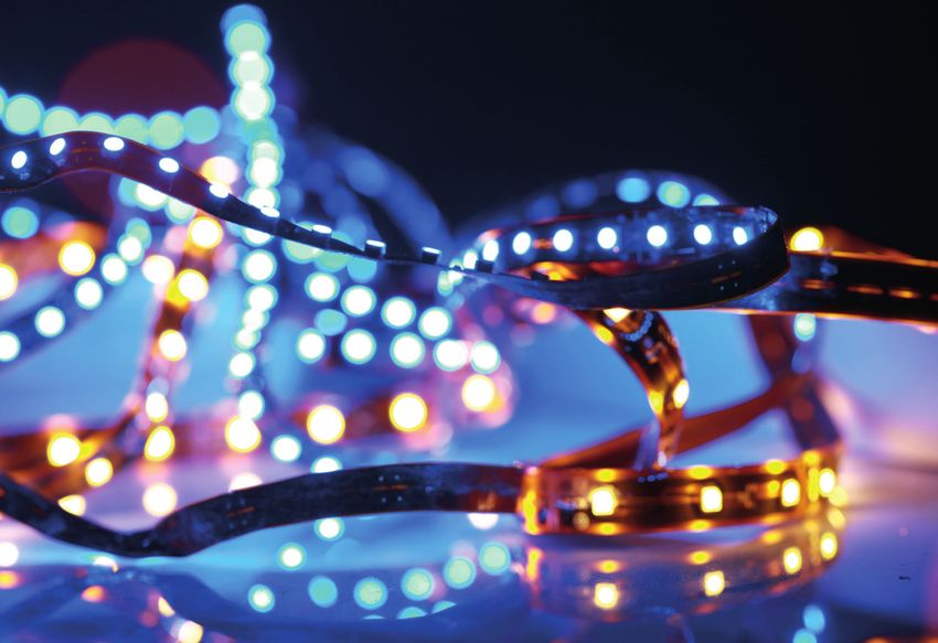
Lighting system overview

                                 Combo IC

                                                                 LED module
 AC line input
                 PFC stage                  Main stage

                                                                   Sensors
                                                                     hub
   Dimmer
                     0–10 V
                                                                Hardware-based
                 dimming interface
                                                                    security

                                                                Wired/wireless
                                     NFC– MCU – communication
                                                                communication

                                                                                 4
LED drivers
    The type of LED drivers used in an LED lighting application     Design strategies usually use analog dimming to a certain
    has a significant impact on key system performance              level and then switch to PWM dimming for lower levels.
    indicators such as:                                             Many customers demand compliance with PFC and THD
    › Efficiency                                                    regulatory requirements at 50 percent dimming.
    › Dimming capability
    › Power quality, i.e. PFC/THD                                   LED drivers based on a single-stage flyback topology
    › Light quality, i.e. ripple/flicker                            usually have an output current ripple of ±30 percent.
    › Configurability of parameters, i.e. output current            Growing dissatisfaction with this ripple is fueling wide-
    › Ability to support add-on features such as                    spread adoption of two-stage topologies, i.e. single-stage
      power monitoring                                              PFC flyback combined with a secondary buck regulator.
    › Product lifetime
                                                                    To date, DIP switches have been typically deployed to
    System efficiency can be influenced by the choice of            configure the output current of LED drivers. The trend is
    topology and the type of components used. A resonant            now moving towards more elegant methods with LED
    topology, for instance, can increase LED driver efficiency by   driver manufacturers and lighting fixture makers opting
    4–5 percent. The right MOSFETs, a high-voltage start-up         for NFC technology, for example. Digital controllers with
    cell and synchronous rectification can also have a positive     a digital interface such as UART enable designers to
    impact. Dimming down to 1 percent light output has              implement power monitoring at luminaire level.
    become mainstream for indoor lighting .
                                                                                                  www.infineon.com/leddrivers

5
LED drivers

Mixed-signal PFC and flyback controllers
ICL8800*/ ICL8810*/ ICL8820*

ICL88xx family of single-stage flyback controllers for constant voltage output is tailored for LED lighting applications to
meet the required performance cost-effectively. They offer benchmarking performance for power factor correction and
total harmonic distortion at full-load as well as at low-load conditions. Also, the controller’s low standby power provides
more margin for smart lighting systems that contain microcontrollers. The jitter function enables fulfillment of EMI
requirements when the luminaire is foreseen to operate as an emergency luminaire.

Features ICL8800                                                   Benefits
› Secondary-Side-Regulated (SSR) Constant Voltage (CV)             › Supporting wide load range and fast and stable reaction
  output flyback controller                                          to dynamic load changes
› Depending on load condition, either quasi-resonant or            › PF > 0.9 and THD < 10% across a wide load range (AC
  discontinuous conduction mode with power factor                    input up to 277 Vrms)
  correction applied                                               › Optimal efficiency, power factor and THD can be achieved
                                                                        by best-suited mode. In addition, DCM eases compliance
ICL8810 contains in addition                                            with EMI at low-load condition
› Active burst mode (ABM) to ensure low standby power
                                                                   ICL8810 contains in addition
ICL8820 contains in addition                                       › Very low standby power < 100 mW enables smart lighting
› Jitter function                                                    in connection with microcontrollers

                                                                   ICL8820 contains in addition
                                                                   › Jitter function enables fulfillment complying with EMI
                                                                     regulations in DC operation, i.e. usage of luminaire as
                                                                     emergency lighting

                                                                                                                           Vout+
                                  Start-up
                                circuit with
                                  BSS126I                                                                                  Vout-

                                                                                        800 V
                                                                  ZCD
                                                  VCC

                                                                                        CoolMOS™
                                                                  GD                    P7
                                                                  CS
                                                        ICL88xx
        DMC                                                       VS

                                                VIN
                                                          GND
                                                  TD

*Coming soon

                                                                                                                                   6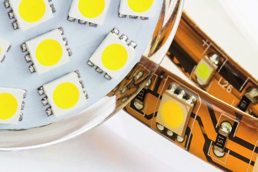
LED drivers

      Mixed-signal PFC and flyback controllers
      BSS126I – High voltage start-up depletion MOSFET

      The most elegant way of reducing the start-up time of an LED driver is the usage of ‚normally-on‘ depletion-mode MOSFET.
      Solutions with start-up resistors consume power not only during the IC‘s start-up also throughout the entire operation.In
      most implementations where the depletion-mode MOSFET is used, these are switched off after start-up.

      Features                                                                     Benefits
      › Normally-on device                                                         › Enables fast time-to-light < 500 ms
      › Can be switched off after start-up                                         › Higher system efficiency than start up resistor solutions
      › Requires very few external components                                      › Increased system reliability due to lower thermal load
      › Small SOT-23 package                                                       › Helps fulfilling low system stand-by power requirements
                                                                                     < 500 mW

                                                                   Start-up current source

      An external HV cell is preferred, e.g., designs with low standby power and no standby power.
      With a depletion MOSFET, even at VGS=0 V current will flow through the device. For a depletion MOSFET, a negative VGS has
      to be applied to turn it off.

                                                                        P7

                             Vin                  BSS126I                                                                Vout

                                                                                                         800 V CoolMOS™ P7
                                                                             ICL88xx

      Application note
       Name                                          Description
       Engineering report for 130W with ICL5102      130 W dimmable constant current LED driver using PFC and LLC
       320 W multichannel high-power LED driver      Engineering Report using ICL5102 + ID8150

      Evaluation board
       Name                            Products                                                  Description
       REF-ICL5102-U130W-CC            ICL5102, 600 V CoolMOS™ CE, BSS126I                       PFC/LLC evaluation board 130 W LED driver
       REF_LLC_BUCK_4CH_320W           ICL5102, ILD8150E, 600 V CoolMOS™ P7, BSS126I             Scalable 320 W multichannel high-power LED driver
                                                                                                 (using ICL5102 and ILD8150)

                                                                                                                       www.infineon.com/bss126i

  7
LED drivers

IRS2982S – single-stage PFC/flyback controller for constant voltage output

Features                                                             Benefits
› Integrated 600 V high-voltage start-up cell                        › Integrated start-up cell enables very high efficiency for
› Multi-mode operation, DCM operation at light loads                   wide-range input designs combined with fast time-to-light
  (minimum off-time)                                                 › Optimal efficiency, power factor and THD can be achieved
› Overvoltage protection                                               by most suited mode. In addition, DCM eases compliance
› Burst-mode operation at very light loads                             with EMI at low load condition by limiting the switching
                                                                       frequency

                                                                                                                                    +VOUT

                                   HV                 VCC

                                   FB                OUT

                                                                                                                800 V CoolMOS™ P7
                                         IRS2982S
AC
line                               COMP              COM
input
                                   ZX                  CS

                                                                                                                                    -VOUT

Application note
 Name                      Description
 ANEVAL_201602_PL16_017    55 W flyback converter design using the IRS2982S controller IRXLED04

Evaluation board
 Name                      Products                                                  Description
 IRLXLED04 50W Flyback     IRS2982S, 800 V CoolMOS™ CE,                              50 W flyback converter design using
 evaluation board*         800 V CoolMOS™ P7                                         the IRS2982S controller

* For more information on the product, contact our product support.
www.infineon.com/irs2982

                                                                                                                                            8
LED drivers

      Mixed-signal PFC and flyback controllers
      IRS2505L – low-cost PFC controller

      Features                                                                         Benefits
      › SOT23-5 package                                                                › 70% smaller than a conventional SO8 package
      › High power factor and ultralow THD over a                                      › Gate driver optimized to eliminate switch-off diode
        wide input range                                                               › Cycle-by-cycle overcurrent protection
      › Zero crossing sensed via the gate drive                                        › Micro power start-up – very low start-up losses
      › PFC inductor auxiliary winding not necessary
      › Critical Conduction Model (CrCM) operation –
        low switching losses

                                                                               LPFC                                       DPFC
                   Rect (+)                                                                                                                     DC bus (+)

                                      RVCC1                                                                                        RB1

                                      RVCC2                                                                                        RB2
                                                                1                               5
                                                                    CMP                 VBUS
                                                   CCMP
                                                                2
                              CRECT                                 COM     IRS2505L                 CVBUS
                                                                                                               MPFC
                                                                                                                                            CBUS

              VCC             DAUX    CVCC1        CVCC2                                                 RG1           600 V
                                                                3                               4
              auxiliary                                             VCC                   PFC                          CoolMOS™ P7
              supply                                                                                                              CC1
                                                                                                                         RC1

                                                                                                                RCS              RVBUS

                   Rect (-)                                                                                                                     DC bus (-)

      Application note
       Name                                   Description
       UG_201705_PL16_05                      Non-isolated two-stage boost PFC plus current-regulated buck LED driver IRXLED09

      Evaluation board
       Name                                   Products                                                 Description
       IRXLED09*                              IRS2505L, 600 V CoolMOS™ P7                              Non-isolated two-stage boost PFC plus current-regulated
                                                                                                       buck LED driver IRXLED09

                                                                             * For more information on the product, contact our product support.
                                                                                                                                 www.infineon.com/irs2505l

  9
LED drivers

ICE2PCS0XG/ICE3PCS0XG – CCM PFC controller

For power ranges above 300 W, CCM PFC mode offers benefits in terms of efficiency compared to DCM PFC mode.

Features                                                             Benefits
› Trimmed internal reference voltage (2.5 V ±1.2%)                   › Enhanced dynamic response
› Low peak current limit threshold                                   › Ease of use with few external components
› Bulk “voltage good” signal for inrush relay control or             › External current compensation for greater user flexibility
  PWM IC enabling
› Integrated digital voltage loop compensation
› Programmable switching (20-100 kHz)
› External synchronization (50 ~ 100 kHz)
› Direct sensing, input brown-out detection with hysteresis

                                                                               600 V CoolMOS™ P7

                              SiC diode

                                                         ICE2PCS0xG
                                                         ICE3PCS0xG

Application note
 Name                       Description
 EVALPFC-300W-ICE3PCS01G    Programmable FF CCM PFC controller ICE2PCS01 for 300 W 393V PFC evaluation board with 85 ~ 265 V AC
                            universal input

Evaluation board
 Name                       Products                                                Description
 EVALPFC2-ICE2PCS01         CCM PFC controller, SiC diode,                          Programmable FF CCM PFC controller ICE2PCS01 for
                            CoolMOS™                                                300 W 393V PFC evaluation board with 85 ~ 265 V AC
                                                                                    universal input

www.infineon.com/pfc-ccm

                                                                                                                                                10
LED drivers
SiC diodes for high-power applications
SiC diodes enable highest efficiency in combination with CCM PFC Controllers in
high power LED applications
Features Benefits
› No reverse recovery charge › System efficiency improvement compared to Si diodes
› Purely capacitive switching › Reduced cooling requirements
› High operating temperature (Tj, max 175 °C) › Enabling higher frequency/increased power density
› Higher system reliability
› Reduced EMI
Continuous forward TO-252 TO-220 TO-247-3 TO-247-2 D2PAK-2
current, IF (DPAK real 2-leg) (real 2-leg)
[A]
2 IDM02G120C5 IDH02G120C5 IDK02G120C5
5 IDM05G120C5 IDH05G120C5 IDK05G120C5
8 IDM08G120C5 IDH08G120C5 IDK08G120C5
10 IDM10G120C5 IDH10G120C5 IDW10G120C5B IDWD10G120C5 IDK10G120C5
15–16 IDH16G120C5 IDW15G120C5B IDWD15G120C5 IDK16G120C5
20 IDH20G120C5 IDW20G120C5B IDWD20G120C5 IDK20G120C5
30 IDW30G120C5B IDWD30G120C5
40 IDW40G120C5B IDWD40G120C5
Pin 1
“B” in product name refers to common cathode configuration: Pin 2 Case
Pin 3
www.infineon.com/sic-diodes
11LED drivers
Digital flyback controllers
XDPL8105 - multi-mode PFC/flyback controller
XDPL8105 is a primary-controlled high-performance single-stage PFC/flyback controller with constant current output.
Features Benefits
› Multi-mode operation, quasi-resonant, › Optimal efficiency, power factor and THD can be achieved
discontinuous conduction mode (DCM) by most suited mode. In addition, DCM eases compliance
› Active burst mode (ABM) with EMI at low load condition by limiting the switching
› Integrated 600 V start-up cell frequency
› Configurable parameters › ABM enables low-level analog dimming
› Supports fully isolated 0 – 10 V dimming › Integrated start-up cell enables very high efficiency for
wide-range input designs combined with fast time-to-light
› Configurability of parameters like output current, pro-
tection modes and dimming curves enables last-minute
adjustments, reducing stockkeeping
85–305
V AC Output
VCC
HV ZCD
800 V CoolMOS™ P7
XDPL8105 GD
Configuration and
CS in-circuit calibration
SQW DIM/UART GND
Dimming circuit +
isolation (optional 0–10 V
via transformer input
or optocoupler)
Application note
Name Description
AN_1904_PL21_1905_103930 40 W demoboard with isolated 0–10 V dimming interface
System Simulation & Design Creation Tool Transformer, BOM and IC parameters
Evaluation board
Name Products Description Order number
REF-XDPL8105-CDM10V XDPL8105, 800 V CoolMOS™ P7 Reference board for XDPL8105 with dimming SP001649474
www.infineon.com/xdpl8105
12LED drivers
Digital flyback controllers
XDPL8210 - multi-mode PFC/flyback controller for 1% dimming
XDPL8210 is a primary-controlled single-stage PFC/flyback controller with constant current output that supports 1% dimming.
Features Benefits
› All features included in XDPL8105 › All benefits included in XDPL8105
› 1% dimming › Well suited for indoor lighting application
› Supports 0-10 V dim-to-off powering the dimmer where 1% dimming is required
› Limited Power (LP) mode › Cost savings for an additional auxiliary power
› PWM dimming input pin supply for the 0-10 V dimmer
› Enables BOM savings for the dimming circuit › Well suited for outdoor lighting in cold areas since LP
mode enables start-up of LEDs even when their forward
voltage is above the nominal output voltage
Iout
90–305
V AC Output
Optional VCC
regulator
CVCC
HV VCC ZCD
800 V CoolMOS™ P7
GD
PWM XDPL8210
CS
GND RCS
Application note
Name Description
ER_1902_PL21_1903_042903 XDPL8210 CDM10VD 35 W reference design with IPN80R900P7 – LED driver with isolated 0 to 10 V dimming and
dim-to-off operation
Evaluation board
Name Products Description Order number
REF-XDPL8210-U35W XDPL8210, 800 V CoolMOS™ P7 XDPL8210 35 W constant current reference board with 0-10 V dimming interface SP001886070
www.infineon.com/xdpl8210
13LED drivers
XDPL8219 – PFC/flyback controller with enhanced total harmonic distortion
XDPL8219 is a high-performance secondary-side regulated flyback controller with constant voltage output and high power
factor with enabling smart lighting applications.
Features Benefits
› Secondary-Side-Regulated (SSR) › Supporting wide load range and fast and stable reaction
Constant Voltage (CV) output to dynamic load changes
› Flyback controller with power factor correction › PF > 0.9 and THD < 10% across a wide load range
› Depending on load condition, either quasi-resonant, (AC input up to 277 Vrms)
discontinuous conduction mode or › Optimal efficiency, power factor and THD can be achieved
active burst mode (ABM) by best-suited mode. In addition, DCM eases compliance
› Integrated 600 V start-up cell with EMI at low-load condition
› Very low stand-by power < 100 mW can be achieved
› Integrated start-up cell enables very high efficiency
Output
Input
CVCC
VCC ZCD
CoolMOS™ P7
800 V
GD
HV CS
XDPL8219
RCS
GND UART FB
Feedback circuit
Application note
Name Description
DG_2005_PL21_2006_124819 XDPL8219 design guide –high power factor flyback converter with constant voltage output
Evaluation board
Name Products Description Order number
REF-XDPL8219U40W XDPL8219, Efficient 40 W reference circuit design for XDPL8219 with high power factor and low SP002990946
800 V CoolMOS™ P7 THD. It is built for universal input voltage 120–277 V AC or 127–432 V DC
www.infineon.com/xdpl8219
14LED drivers
Digital flyback controllers
XDPL8221 – two-stage intelligent & configurable PFC plus flyback controller
XDPL8221 is a digital quasi-resonant PFC + flyback controller with communication including dimming and reading out
of data like fault condition and power monitoring via UART.
Features Benefits
› Two-stage Power Factor Correction (PFC) and › Enables the design of high performance advanced LED
flyback controller driver for connected lighting with small effort
› Primary-Side-Regulated (PSR) multi-mode control: › Maximize flexibility for global platform designs
Constant Current (CC), Constant Voltage (CV) › Reduce product variants and inventory management
and Limited Power (LP) complexity
› Pulse Width Modulation (PWM) dimming control › 1% dimming and dim-to-off
› Total harmonic distortion optimization › Further improved THD < 15%
(QR compensation)
L
600 V CoolMOS™ P7
Input XDPL8221 LED+
voltage
CoolMOS™ P7
GDPFC
800 V
CSPFC GDFB
CSFB
N LED-
TEMP
VCC
HV
VS ZCD
GND
UART PWM PWM
UART GND VSupply
Application note
Name Description
DG_1711_PL21_1712_143020 XDPL8221 digital PFC + flyback controller IC – a high-performance dual-stage digital PFC + flyback AC-DC converter
using the XDPL8221 controller for LED lighting applications
AN_1901_PL21_1902_043849 XDPL8221 limited power mode – the Limited Power (LP) mode of XDPL8221, and the dimming operation in LP mode
AN_1901_PL21_1902_071326 XDPL8221 CSV file parameter description for 50 W reference design – the parameters defined in the CSV file for the
XDPL8221 digital controller
Evaluation board
Name Products Description Order number
REF-XDPL8221-U50W XDPL8221, Efficient and flicker-free reference circuit design for XDPL8221 with high power SP003127452
700 V and 800 V factor and low THD. It is built for universal input voltage (100–277 V AC) and for
CoolMOS™ P7 50 W output power
REF-XDPL8221-U100W XDPL8221, 600 V Efficient and flicker-free reference circuit design for XDPL8221 with high power SP001710982
CoolMOS™ C6 and factor and low THD. It is built for universal input voltage (100–277 V AC) and for
800 V CoolMOS™ P7 100 W output power
www.infineon.com/xdpl8221
15LED drivers
PFC plus half-bridge resonant controllers
ICL5102
ICL5102 is a PFC plus half-bridge resonant controller that has excellent PFC and THD performance combined with
high-frequency operation in order to minimize the bill of materials.
Features Benefits
› Integrated two-stage combination controller › Simplify system design for PFC plus LLC/LCC topologies with
› Supports universal AC nominal input voltage less component counts and optimized bill of materials (BOM)
(90 to 305 VRMS) and form factor
› Excellent system efficiency of up to 94% › Address global platforms with one IC
› THD optimization ensures low harmonic distortion › Strong efficiency, PF and THD performance packaged in
(Total Harmonic Distortion (THD) < 5%) down to 30% a combo-IC
nominal load › Integrated coreless transformer offers robustness against dV/
› Maximum 500 kHz HB switching frequency and dt, negative voltage
soft-start frequency up to 1.3 MHz › Minimize form factors due to high switching frequency capability
ICL5102 – typical application with PFC + LCC topology
LPFC ROVP_2 ROVP_1
CR1
600 V CoolMOS™ P7 600 V CoolMOS™ P7
PFCZCD
OVP
VACIN HSGD
600 V CoolMOS™ P7
HSVCC
LR LM L4_3
VOUT+
PFCGD HSGND
ICL5102 CR2 CR3 VOUT-
DBO1 DBO2
PFCVS LSGD
PFCCS LSCS L4_4
CV and CC regulator
GND
OTP
VCC
BM
BO
RF
RBO1
RBM RBM_DA SFH617-A3
RBO2 CVCC
RF_min NTC
Application note
Name Description
Engineering report for 52 W with IC5102 52 W low-cost two-stage LED driver based on ICL5102
Engineering report for 130 W with ICL5102 130 W dimmable constant current LED driver using PFC and LLC
320 W multichannel high-power LED driver Engineering Report using ICL5102 + ID8150
Evaluation board
Name Products Description Order number
REF-ICL5102-U52W-CC ICL5102, 600 V CoolMOS™ P7 Low-cost PFC/LCC evaluation board SP005419724
52 W LED driver
REF-ICL5102-U130W-CC ICL5102, 600 V CoolMOS™ CE, BSS126I PFC/LLC evaluation board 130 W LED driver SP001667160
REF_LLC_BUCK_4CH_320W ICL5102, ILD8150E, 600 V CoolMOS™ P7, BSS126I Scalable 320 W multichannel high-power SP005424809
LED driver (using ICL5102 and ILD8150)
www.infineon.com/icl5102
16LED drivers
ICL5102HV
ICL5102HV is a PFC plus resonant combo controller that has excellent PFC and THD performance combined with high-fre-
quency operation in order to minimize the bill of materials.
Features Benefits
› All features mentioned in ICL5102 › All benefits mentioned in ICL5102
› High voltage (HV) version supports (90 to 480 VRMS) › ICL5102HV can be used in street lighting, horticultural
lighting and industrial lighting where 480 V AC is used
as input voltage
ICL5102HV – typical application with PFC + LLC topology
LPFC ROVP_2 ROVP_1
CR1
900 V CoolMOS™ C3 900 V CoolMOS™ C3
PFCZCD
OVP
VACIN HSGD
950 V CoolMOS™ P7
HSVCC
LR LM L4_3
VOUT+
PFCGD HSGND
ICL5102HV CR2 CR3 VOUT-
DBO1 DBO2
PFCVS LSGD
PFCCS LSCS L4_4
CV and CC regulator
GND
OTP
VCC
BM
BO
RF
RBO1
RBM RBM_DA SFH617-A3
RBO2 CVCC
RF_min NTC
Application note
Name Description
Reference design for 150W with ICL5102HV 150 W LCC LED driver demonstration board with ICL5102HV
Evaluation board
Name Products Description Order number
REF-ICL5102HV-U150W ICL5102HV, ICL5102HV 150 W LED driver board with SP005346355
900 V CoolMOS™ C3* and Vin up to 480 V
950 V CoolMOS™ P7,
IPD530N15N3 G
www.infineon.com/icl5102hv *Replacement for CoolMOS™ C3 is CoolMOS™ P7
17LED drivers
DC-DC buck converters and smart linear controller
ILD8150 – 80 V DC-DC buck LED driver IC
ILD8150 is a DC-DC LED driver IC with 80 V breakdown voltage with an integrated MOSFET.
Features Benefits
› Input voltage up to 80 V › High safety margin for voltage transients and spikes
› Integrated MOSFET for up to 1.5 A output current › Optimal BOM due to integrated MOSFET
› Analog dimming down to 12.5% and › Deep dimming performance without flicker and noise via
PWM dimming from 12.5% to 0.5% innovative one-pin hybrid method
› Current precision ±3% › High current precision leads to high light quality
› Soft-start, UVLO, current limitation, low-power shutdown › Fast, stable and efficient regulation
BOOT
DIM SW
SD
ILD8150/ILD8150E
VIN CS
VCC
80 V
GND
Application note
Name Description
REF_ILD8150_DC_1.5A high frequency operation High-frequency operation with ILD8150
Reference board REF_ILD8150_DC_1.5A LED driver IC ILD8150 80V Operation, design guide and performance
320 W multichannel high-power LED driver Engineering Report using ICL5102 + ID8150
Evaluation board
Name Products Description Order number
REF_ILD8150_DC_1.5A ILD8150E Reference design board 1.5 A with coil inductor SP002798058
REF_ILD8150_DC_1.5A_SMD ILD8150E Reference design board 1 A with SMD inductor SP005351260
REF_LLC_BUCK_4CH_320W ICL5102, ILD8150E, 600 V CoolMOS™ P7, Scalable 320 W multichannel high-power LED SP005424809
BSS126I driver (using ICL5102 and ILD8150)
REF_TW_ILD8150E_60V_1A* ILD8150E, IFX1117ME V33 Reference board for professional tunable SP005433043
white and multichannel applications
www.infineon.com/ild8150
*Coming soon www.infineon.com/ild8150e
18LED drivers
BCR601/BCR602 - 60 V linear LED controller ICs for Tunable White plus active
headroom control and flexible dimming
BCR601 is a linear controller that enables high efficiency at low cost as a second-stage LED controller to replace DC-DC buck
converters especially in low- to mid-power LED drivers. The cost-effectiveness especially in multichannel designs can be further
enhanced by using BCR602 in a tiny SOT23-6 package regulating the LED current for flicker-free deep dimming performance.
Features Benefits
› BCR601 as the master controller controls voltage › Linear regulators give considerable cost advantage over
overhead of both channels and current of one channel buck topology
› BCR602 as slave controller regulates current of second channel › Cost advantage increases with additional channels
› Input voltage up to 60 V › Efficiency can be on par with buck (depends on output
› Can be operated with either BJT or N-channel MOSFET ripple of first stage)
› Analog dimming down to 3%, PWM dimming › Highest light quality, zero ripple
down to 1% (BCR602) › Deep, full analog dimming
› Current precision ±3% › Easy to extend to additional outputs (e.g. RGBW)
› OTP, OVP, hot-plug protection
Cout ROV1
RB
ROV2
D1
D2
CFB
ROC RFB RD
OVP VDROP
Q1 Q2
VS DRV VS DRV
BCR601 BCR602
DP10 GND TTST GND
VF10 VSENSE MFID VSENSE
Dim_In_CW Dim_In_WW
Application note
Name Description
Tunable white LED drivers with BCR601 and BCR602* Application note describing how to design cost-effective, highly-efficient
LED drivers of highest light quality
Design guide lighting ICs linear LED controller 60V BCR601 Design guide for a linear LED controller IC with feedback loop to primary side
BCR602 linear LED controller for dimmable applications Design guide for a secondary side current regulated 60 V LED light engine
BRC602 engineering report Engineering report demoboard DEMO_BCR602_60V_ICTRL – engineering report
for a 60 V, 200 mA linear LED controller demonstration board
Evaluation board
Name Products Description Order number
REF_TW_BCR601_55V_0.5A* BCR601, BCR602 Demoboard for design evaluation of Tunable White SP005433044
applications with cost-effective linear LED controllers
DEMO_BCR601_60V_IVCTRL BCR601, BSP716N This board is intended for the design evaluation of very SP002798056
cost-efficient, highly reliable, power-efficient LED drivers
with linear LED driver IC BCR601
DEMO_BCR602_60V_ICTRL BCR602, BSP716N Demoboard for design evaluation of cost-efficient, highly SP002798054
reliable, dimmable LED engines/modules, 60 V, 200 mA
www.infineon.com/bcr601
www.infineon.com/bcr602 *Coming soon
19LED drivers
DC-DC buck converters and smart linear controller
BCR601 – 60 V linear LED controller with active headroom control
BCR601 is a linear controller that enables high efficiency at low cost as a second-stage LED controller to replace DC-DC buck
converters especially in low- to mid-power LED drivers.
Features Benefits
› Input voltage up to 60 V › Well suited for LED drivers with SELV
› Voltage feedback to primary side › Reducing voltage overhead and power loss in transistor
› Can be operated with either BJT or N-channel MOSFET for better system efficiency
› Analog dimming down to 3% › Cost and performance can be optimized by selection of
› Current precision ±3% BJT or N-channel MOSFET
› OTP, OVP, hot-plug protection › High light quality without flicker
› Safe operation
Cin
ROVP1
ROVP2 COVP
Controller
IC
CDROP
ROPTO RDROP
OVP VDROP
Rpred
VS DRV or
BCR601
OPTO GND
DAC MFIO VSENSE
Rset Rsense
CPI RPI
Application note
Name Description
Design guide lighting ICs linear LED controller 60V BCR601 Design guide for a linear LED controller IC with feedback loop to primary side
Engineering report demoboard DEMO_BCR601_60V_IVCTRL Engineering report for 60 V, 500 mA linear LED controller demonstration board
Evaluation board
Name Products Description Order number
DEMO_BCR601_60V_IVCTRL BCR601, BSP716N This board is intended for the design evaluation of very cost-efficient, SP002798056
highly reliable, power-efficient LED drivers with linear LED driver IC BCR601
www.infineon.com/bcr601
20LED drivers
IRS2982 – universal controller for high voltage buck
IRS2982 is a multi-mode LED driver IC that can be used for the flyback stage mainly for constant voltage output as well as for
the buck stage of non-isolated PFC boost followed by a high-voltage buck.
Features Benefits
› Integrated 600 V high-voltage start-up cell › Integrated start-up cell enables very high efficiency for
› Multi-mode operation, DCM operation at light loads wide-range input designs combined with fast time-to-light
(minimum off-time) › Optimal efficiency, power factor and THD can be achieved
› Overvoltage protection by most suited mode. In addition, DCM eases compliance
› Burst-mode operation at very light loads with EMI at low load condition by limiting the switching
frequency
Second-stage buck convertor using IRS2982S VBUS
Output power = 75 W
Output voltage = 60–200 V
Output current = 350 mA
1 8
HV VCC VCC2
2
2 7 1 600 V CoolMOS™ P7 VFB
VFB IFB OUT
VOUT
IRS2982 3
COMP 3 6
COMP COM COMB
OUT+
4 5 P3
VZX ZX CS COMB
2
1
COMB COMB COMB GND
Supply for IRS2982 IC and optocoupler ZX detection
VCC_PFC VCC2 VBUS VZX
COMB COMB
Application note
Name Description
AN_1808_PL16_1809_234920 Non-isolated two-stage boost PFC plus current-regulated buck LED driver IRXLED10
Evaluation board
Name Products
IRXLED10* IRS2505L, IRS2982S, 600 V CoolMOS™ P7 (IPP60R360P7)
www.infineon.com/irs2982s * For more information on the product, contact our product support.
21LED drivers
CoolMOS™ – high-voltage MOSFETs
Trusted leader in high-voltage MOSFETs
CoolMOS™ is an extremely well-established technology in Another product family that has seen very high traction
LED driver applications. The main reasons why LED driver among lighting customers is the 950 V P7 family. Optimized
customers choose CoolMOS™ include: for flyback topologies, where breakdown voltages above
800 V are required, 950 V P7 devices are emerging as the
› Proven quality and reliability solution of choice among our customers.
› High efficiency
› High-volume supply capability Our 600 V P7 portfolio is designed for high efficiency
› Continuous portfolio expansion across all higher-power applications with an RDS(on) of up to
600 mΩ. For lower-power applications that require 600 V
For new designs, many LED driver makers are opting for with an RDS(on) of > 600 mΩ, we recommend either 600 V CE
the newest generation of CoolMOS™, namely the P7 family. or 700 P7 devices. 700 V P7 is well suited to the PFC and fly-
Highlights of this latest generation include the best price/ back stage. 600 V CE is a universal solution that can be used
performance ratio and highly granular RDS(on) classes com- in all low-power topologies with an RDS(on) of > 600 Ω.
bined with diverse packages.
Aware that security of supply is a key success factor for our
The SOT223 package, footprint-compatible with standard customers, we usually manufacture our products at multi-
DPAK packages, has been a great success story in the light- ple factories. This aspect might be considered for designs
ing industry. where superior performance of CoolMOS™ can help to
differentiate your products from competitors.
CoolMOS™ superjunction MOSFETs for lighting applications
950 V P7 1)
900 V C3
800 V CE 800 V P7 1)
800 V C3
700 V P7 1)
600/650 V C6/E6 650/700 V CE
500/600/650 V C3 600 V CE 600 V P7
600 V P6
600 V CE
Not for new design Active Active and preferred
Time
1) Optimized for flyback topologies Price-performance
www.infineon.com/coolmos
22LED drivers
950 V CoolMOS™ P7
Designed to meet growing consumer needs in the high-voltage MOSFET arena, the latest 950 V CoolMOS™ P7 technology
focuses on lighting.
Temperature @ 90 V AC › The new 950 V CoolMOS™ P7 series delivers best-in-class
performance in terms of efficiency, thermal behavior and
65 Δ 5.2°C
ease of use. Like all other P7 family members, the
60
950 V CoolMOS™ P7 series comes with an integrated
55
Temperature [°C]
Zener diode for ESD protection. This integrated diode
50
considerably improves ESD robustness, thus reducing
45
IPA90R500C3 ESD-related yield loss and offering exceptional ease of use.
40
35
Competitor › Plug-and-play at 90 V AC in a 40 W reference design,
IPA95R450P7
featuring the snubberless concept, demonstrates
30
excellent efficiency gains of up to 0.2 percent, plus
25
5 10 15 20 25 30 35 40 lower MOSFET temperatures with drops of up to 5.2°C
Pout [W] compared with similar competitor technology.
› In the DPAK package, the 950 V CoolMOS™ P7 also offers
best-in class RDS(on). This SMD device has an RDS(on) of
450 mΩ – more than 60 percent lower than that of the
closest competitor.
1400
1200 mΩ
Best-in-class DPAK RDS(on)
1250 mΩ
1200 Customer benefits
1000 › Option to change from leaded to SMD packages
› High power density
RDS(on) [mΩ]
-65%
800
› Lower BOM
600
450 mΩ › Lower production cost
400
200
0
Competitor CoolMOS™ C3 CoolMOS™ P7
www.infineon.com/950v-p7
23LED drivers
CoolMOS™ – high-voltage MOSFETs
800 V CoolMOS™ P7
With the 800 V CoolMOS™ P7 series, we have set a This technology optimizes key parameters to deliver
benchmark in 800 V superjunction technologies, combining best-in-class efficiency and thermal performance. As
best-in-class performance with remarkable ease of use. demonstrated through comparisons with a standard,
This new product family is a perfect fit for flyback-based commercially available 80 W LED driver, it reduces
LED driver applications. It is also suitable for PFC stages, switching losses (Eoss) and output capacitance (Coss) by
offering a price/performance ratio to meet all market more than 45 percent while significantly improving the
needs. input capacitance (Ciss) and gate charge (QG). All of which
leads to a 0.5 percent increase in efficiency at light load,
which helps to reduce standby power in the end application.
At full load, the observed improvement is up to 0.3 percent
for efficiency coupled with a 6°C drop in device temperature.
Plug and play in an 80 W LED driver from market As mentioned in the introduction, the choice of MOSFET will
influence system efficiency. Due to benchmark switching
0.6
losses, the 800 V CoolMOS™ P7 series can achieve very high
0.5 levels of system efficiency. This efficiency gain relative to
Relative efficiency [%]
0.4 market-standard products widens under dimming
conditions.
0.3
0.5%
0.2 Compared with the competition, the 800 V CoolMOS™ P7
0.3%
0.1
technology allows designers to integrate much lower RDS(on)
values into small and cost-effective packages such as DPAK.
0 The same applies to even smaller and low-cost packages
0 10 20 30 40 50 60 70 80 90
Pout [W] like SOT223. The 800 V P7 in a SOT223 package is
footprint-compatible with the DPAK.
CoolMOS™ P7 CoolMOS™ C3
Competitor 1 Competitor 2
Overview of lowest DPAK RDS(on) CoolMOS™ P7 sets a new benchmark in best-in-class
for 800 V superjunction MOSFET DPAK RDS(on)
850 mΩ
Customer benefits
› High power density
630 mΩ
› Lower BOM
450 mΩ -56% › Lower production cost
360 mΩ
280 mΩ
Competitor 2 Competitor 1 CoolMOS™ P7 CoolMOS™ P7 CoolMOS™ P7
The complete P7 platform has been developed with an integrated Zener diode to protect against electrostatic discharge
(ESD). This increases the overall device ruggedness up to Human Body Model (HBM) class 2.
www.infineon.com/800V-p7
24LED drivers
700 V CoolMOS™ P7
Features Benefits
› High-performance technology › Cost-competitive technology
– Low switching losses (Eoss) › Further efficiency gain at higher switching speeds
– Highly efficient › Smaller magnetic size with lower BOM
– Excellent thermal behavior › High ESD ruggedness up to HBM class 2
› Support for high-speed switching › Easy to drive and design-in
› Integrated protection with Zener diode › Enabler for smaller form factors and high power density
› Optimized VGS(th) (3 V) with very narrow tolerance (±0.5 V) designs
› Highly granular portfolio › Best-fit product for demanding applications
There are two main use cases for 700 V LED drivers. The The second use case is as a single-stage flyback design for
main one is as a PFC stage for outdoor lighting, where 600 V narrow-range systems with 120 V and 230 V input voltages.
might be borderline. For outdoor lighting, some LED driver 800 V MOSFETs will probably remain the devices of choice for
designs have been deploying 650 V MOSFETs due to higher single-stage flyback designs. Rising cost pressures for some
surge requirements relative to indoor lighting schemes. narrow-range designs may position 700 V as a cost-effective
700 V CoolMOS™ P7 is a highly cost-effective alternative to alternative to 800 V MOSFETs.
the 650 V MOSFETs with the added bonus of extra buffer.
Relative efficiency @ 230 VAC; Relative temperature @ 230 VAC;
Tamb = 25°C Tamb = 25°C, 30 min burn-in
0.5 18
0 16
16
-0.5 14 13
∆ 1.5%
-1.0
∆Efficiency [%]
12
∆Temp [K]
-1.5
∆ 4% 10
-2.0 ∆ 16 K
8
-2.5
-3.0 6 5
-3.5 4
-4.0 2
-4.5 0
0 0.5 1 1.5 2 2.5 3
Iout [A]
CoolMOS™ P7 CoolMOS™ C6 CoolMOS™ P7 CoolMOS™ C6
Competitor 1 Competitor 2 Competitor 1 Competitor 2
www.infineon.com/700V-p7
25LED drivers
CoolMOS™ – high-voltage MOSFETs
600 V CoolMOS™ P7
The 600 V CoolMOS™ P7 can be used for very different against hard commutation, making it suited to hard- and
stages within LED drivers. soft-switching topologies such as LLC.
› PFC stage In addition, excellent ESD capability helps to improve the
› Half-bridge stage manufacturing quality.
› Buck stage
The 600 V CoolMOS™ P7 family offers a wide range of
It offers the highest efficiency and improved power density RDS(on)/package combinations, including THD and SMD
due to significant reduction in gate charge (QG) and switching devices, with RDS(on) scaling from 24 to 600 mΩ. This device
losses (EOSS) levels, coupled with optimized RDS(on). offers the most competitive price/ performance ratio of all
600 V CoolMOS™ offerings.
The carefully selected integrated gate resistors enable very
low ringing tendency. The body diode is exceedingly robust Above 600 mΩ, a 600 V CoolMOS™ CE is recommended.
Features Benefits
› Suitable for hard and soft switching (PFC and LLC) due to › Ease of use and fast design-in thanks to low ringing
outstanding commutation ruggedness tendency and suitability for PFC and PWM stages
› Optimized balance between efficiency and ease of use › Improved efficiency and simplified thermal management
› Significant reduction of switching and conduction losses due to low switching and conduction losses
leading to low MOSFET temperature › Higher manufacturing quality due to > 2 kV
› Excellent ESD robustness > 2 kV (HBM) for all products ESD protection
› Better RDS(on)/package combinations than the competition › Increased power density by decreasing device footprint
› Large portfolio with granular RDS(on) values, qualified for › Suitable for a wide variety of applications and power
a variety of industrial and consumer applications ranges
CoolMOS™ P7 CoolMOS™ P6 CoolMOS™ C7 CoolMOS™ CE
Efficiency
Portfolio Low ringing
Commutation
Price competitiveness
ruggedness
ESD
www.infineon.com/600V-p7
26LED drivers
OptiMOS™ 5 – medium-voltage MOSFETs
OptiMOS™ 5 150 V for synchronous rectification
The wide OptiMOS™ portfolio ranging from 100 V to 250 V enables the highest efficiency levels in synchronous rectification.
OptiMOS™ consistently sets the benchmark for key design success factors including RDS(on), leading to reduced power losses
and improved overall efficiency.
Features Benefits
› Ultralow reverse recovery charge › Increased commutation ruggedness
› Suitable for low-voltage drives › Significant drop in design effort
› RDS(on) up to 25 percent lower than next-best alternative in › Optimized system efficiency
SuperSO8
› Qrr without compromising FOMgd and FOMOSS
OptiMOS™ 150 V normal level
RDS(on) max @ VGS = 10 V TO252 (DPAK) SuperSO8
[mΩ]
16–30 IPD200N15N3 G RDS(on) = 20.0 mΩ BSC190N15NS3 G RDS(on) = 19.0 mΩ
IPD530N15N3 G RDS(on) = 53.0 mΩ BSC360N15NS3 G RDS(on) = 36.0 mΩ
30–60
BSC520N15NS3 G RDS(on) = 52.0 mΩ
RDS(on) max @ VGS = 10 V TO-263 TO-263 TO-262 TO-220 SuperSO8 PQFN 3.3 x 3.3
[mΩ] D2PAK D2PAK 7pin I2PAK PQFN 5 x 6
IPB048N15N5 IPB044N15N5 IPI051N15N5 IPP051N15N5
4.0–5.1
RDS(on) = 4.8 mΩ RDS(on) = 4.4 mΩ RDS(on) = 5.1 mΩ RDS(on) = 5.1 mΩ
IPB073N15N5 IPB060N15N5 IPI076N15N5 IPP076N15N5 BSC093N15NS5
RDS(on) = 7.3 mΩ RDS(on) = 6.0 mΩ RDS(on) = 7.6 mΩ RDS(on) = 7.6 mΩ RDS(on) = 9.3 mΩ
5.2–11.0
BSC110N15NS5
RDS(on) = 11.0 mΩ
BSC160N15NS5 BSZ300N15NS5
> 11.0
RDS(on) = 16.0 mΩ RDS(on) = 30.0 mΩ
www.infineon.com/optimos-150v
27LED drivers
NFC IC for configuration
NLM0010/NLM0011
Infineon’s NLM0011 is a dual-mode NFC wireless configuration IC with CLO and Pulse Width Modulation (PWM) output,
primarily designed for LED applications to enable NFC programming. In addition, advanced features such as the Constant
Lumen Output (CLO) as well as the on/off counting are integrated, with no need for an additional microcontroller. The
NLM0010 is a light version of the NLM0011 without CLO function.
Features Benefits
› Configurable Pulse Width Modulation (PWM) output › Fast and cost-effective implementation of NFC
› NFC contactless interface compliant with ISO/IEC 18000-3 programming and CLO without the need for an additional
mode 1 (ISO/IEC 15963) microcontroller
› Constant Lumen Output (CLO) with 8 configurable points › Compatible with most analog LED driver designs using
for NLM0011 “plug-in resistor” method
› Integrated operation-time counter (OTC) and › Stable PWM output with fixed 2.8 V amplitude and ±0.1%
on/off counter duty cycle accuracy
› Non-volatile memory (NVM) including UID › Internal voltage regulator (LDO) to avoid influence of
unstable external supply voltage
Current-adjustable
LED driver IC
IADJ
ISET
ADIMM
R1
PWM LB
C1
NLM0011/
GND
NLM0010
CVCC
VCC VCC LA
GND
Application note
Name Description
NLM0011 Dual-mode NFC configuration IC with PWM output and CLO function
NLM0010 Dual-mode NFC configuration IC with PWM output, without CLO function
Evaluation board
Name Products Description Order number
EVAL_NLM0011_DC NLM0011, IFX20002MBV33, NLM0011 evaluation kit - LED power SP005298736
BCM846SH6327XTSA1 supply with current configuration
using NFC-PWM IC
www.infineon.com/nlm0010
www.infineon.com/nlm0011
28LED drivers
0–10 V dimming interface IC
CDM10V – integrated analog-to-PWM converter for 0–10 V dimming
Features Benefits
› Simplest 0–10 V dimming IC with default settings › Replace many external components with a single chip,
– 5% minimum duty cycle reducing BOM and PCB space
– 1 kHz PWM frequency › Minimize variation from device to device thanks to
– 200 µA dimmer/resistor bias current embedded digital signal processing
– Dim-to-off disabled › Easily customizable to design requirements
› The simple one-time programmable option allows setting › Suitable for various VCC scenarios
selection in a wide range › Wide input VCC range from 11 to 25 V
– Minimum duty cycle: 1%, 2%, 5%, 10% › Versatile in complex dimming design
– PWM output frequency: 200 Hz, 500 Hz, 1 kHz, 2 kHz
– Dimmer/resistor bias current: 50 µA, 100 µA, 200 µA, 500 µA
– Dim-to-off: disabled/enabled
› Wide input VCC range from 11 to 25 V
› Transparent PWM mode
(PWM bypass mode in dim-to-off-enabled mode)
Vout
VCC
GD 50 µA
1 6 Rdim+
CS
Controller
2 Dimming 5
IC
IC
3 4
MFIO
Application note
Name Description
CoolDim10V Demoboard 40 W reference design with CDM10V isolated 0–10 V dimming interface
COOLDIM_PRG_BOARD User manual for CDM10V programming board
Evaluation board
Name Products Description Order number
COOLDIM_PRG_BOARD CDM10V 10 V programming board for CDM10V SP001493166
REF-XDPL8105-CDM10V CDM10V, XDPL8105 Reference board for XDPL8105 with dimming SP001649474
REF-XDPL8210-U35W CDM10V, XDPL8210, 35W reference board with isolated 0 to 10 V SP001886070
800 V CoolMOS™ P7, dimming and dim-to-off operation
BSS169, BSS123N
www.infineon.com/cdm10v
29LED strips and signage
LED strips are being used everywhere from gas stations to current sources have been well established for the LED
cruise ships in a growing number of applications ranging strings. These current sources provide from 10 mA to
from channel letters to long LED chains. In commercial 200 mA LED current compared to the mainstream range
applications - where product lifetime as well as a of 20 mA to 100 mA.
homogeneous light output are key priorities - constant
www.infineon.com/ledstripsandsignage
30LED strips and signage
Linear LED driver ICs
The BCR linear LED drivers are perfectly suited for driving
LED currents from 10 mA to 250 mA, making them the
ideal choice for low- to mid-power LEDs in general lighting
applications.
This represents the lowest-cost solution that requires an
ultralow external part count and PCB space. The light
output can be adjusted via an external resistor. PWM
dimming is supported either by a microcontroller
interface or by means of an external digital transistor.
Thanks to its negative thermal coefficient, the LED load will
be protected from overheating.
The new-generation BCR430U and BCR431U drivers feature
an extra-low voltage drop and a smart temperature con-
trolling circuit.
Low-power LED driver ICs (5–65 mA)
Product type Group Topology VS (min) VS (max) Iout (typ) Iout (max) Dimming Package Ptot (max)
[V] [V] [mA] [mA] [mW]
BCR401U LED drivers for low-power LEDs Linear 1.4 + VfLED 40 10 65 Digital SC74 750
BCR401W LED drivers for low-power LEDs Linear 1.2 + VfLED 18 10 60 Digital SOT343 500
BCR402U LED drivers for low-power LEDs Linear 1.4 + VfLED 40 20 65 Digital SC74 750
BCR402W LED drivers for low-power LEDs Linear 1.4 + VfLED 18 20 60 Digital SOT343 500
BCR405U LED drivers for low-power LEDs Linear 1.4 + VfLED 40 50 65 Digital SC74 750
BCR431U LED drivers for low-power LEDs Linear 6 42 15 42 Digital SOT23-6 600
Medium and high-power LED driver ICs (65–500 mA)
Product type Group Topology VS (min) VS (max) Iout (typ) Iout (max) Dimming Package Ptot (max)
[V] [V] [mA] [mA] [mW]
BCR430U LED drivers for mid-power LEDs Linear 6 42 50 100 Digital SOT23-6 600
BCR320U LED drivers for mid-power LEDs Linear 1.4 + VfLED 24 + VfLED 250 300 No SC74 1000
BCR321U LED drivers for mid-power LEDs Linear 1.4 + VfLED 24 + VfLED 250 300 Digital SC74 1000
BCR420U LED drivers for mid-power LEDs Linear 1.4 + VfLED 40 + VfLED 150 200 No SC74 1000
BCR421U LED drivers for mid-power LEDs Linear 1.4 + VfLED 40 + VfLED 150 200 Digital SC74 1000
BCR450 LED controllers Linear 3 27 70 ext. switch Digital SC74 500
TLE4309G LED drivers for linear Linear 4.5 24 500 500 Digital TO263 –
high-power LEDs
www.infineon.com/bcr
31LED strips and signage
Very low-cost LED driver ICs
BCR401W/ BCR402W
Features Benefits
› Up to 500 mW power dissipation in a small SOT343 package › Driving current always under control for homogeneous
› Negative thermal coefficient reduces output current at light output
higher temperatures › Longer lifetime of the LEDs due to reduced output current
› Automotive qualified according to AEC-Q101 at higher temperatures (negative thermal coefficient)
› Suitable for a wide variety of applications and power ranges › Easy paralleling of drivers to increase current
› Output current adjustable by resistor up to 60 mA › Stacking of LEDs in front of driver to increase input voltage
› High-side current control › Contributes to longevity and reliability of LED system
› PWM dimmable by external transistor
RSense
(optional)
BAS3010-03W
VS = 12 V DC
(optional)
Rext VS
BCR402W
GND Iout
ON/
LEDs
OFF
(optional)
Application note
Name Description
AN182 Comparison of resistor biasing versus BCR401W/BCR402W LED driver biasing of 12 V & 24 V DC low-current
LED strip lights
Evaluation board
Name Products Description Order number
BCR402W 12V LED BOARD BCR402W 12 V demoboard driving SP000748242
BAS3010A-03W 3x 0.2 W LEDs in series
BCR402W 24V LED BOARD BCR402W 24 V demoboard driving SP000748244
BAT64-02W 6x 0.2 W LEDs in series
www.infineon.com/bcr401w
www.infineon.com/bcr402w
32LED strips and signage
Low-voltage-drop LED driver ICs
BCR430U/ BCR431U
Features Benefits
› Max. 200 mV voltage drop at driver stage › Very low voltage drop allows use of more LEDs or longer
› Supply voltage from 6 to 42 V strips overall, which means fewer feeding points.
› Controls up to 100 mA LED current (BCR430U) › Flexible current setting via resistor
› Controls up to 42 mA LED current (BCR431U) › Homogeneous light output
› Smart overtemperature protection › OTP: protecting not only the lifetime of the IC but also can
be used to protect the reliability of the LED strip
IN+
N.C. LED
GND BCR430U N.C.
IN-/GND
RS VS
Application note
Name Description
ER_201704_PL39_0 Engineering report linear LED driver IC BCR430U – features and performance for a 24 V/100 mA
(max. LED current) solution, with explanations covering circuit and layout design for the demoboard
ER_2001_PL39_100719_ Engineering report linear LED driver IC BCR431U – features and performance for a 24 V/40 mA (max. LED current)
BCR431U_2020-02-10 solution, with explanations covering circuit and layout design for the demoboard
BCR431U Low voltage drop BCR431U – linear LED driver IC with low voltage drop – application note – operation, design guide and performance
LED driver IC App Note
Evaluation board
Name Products Description Order number
BCR430U LED BOARD BCR430U Low-power demoboard with SP001709472
8 LEDs, 50 mA
DEMO_BCR431U_LVDROP BCR431U Low-power demoboard with SP005351261
8 LEDs, 15 mA
www.infineon.com/bcr430u
www.infineon.com/bcr431u
33LED strips and signage
Robust LED driver ICs
BCR320U/BCR420U
Features Benefits
› Homogeneous light output in different LED strings regard- › Direct microcontroller interface for PWM dimming for
less of Vf and supply voltage BCR421U and BCR321U or dimming via PWM power
› Easy to implement with a low component count › Negative thermal coefficient to protect the lifetime
› Flexibility to adjust the current via an external resistor of LEDs
from 10 mA up to 250 mA › High power dissipation capability
› Automotive qualified according to AEC-Q101
BAS3007A-RPP
(optional)
+ VS = 24 V DC
-
GND Iout
Rext Iout BCR320U Iout
Rext IEN
Microcontroller
Infineon component list
Product type Description
BCR320U/BCR321U/BCR420U/BCR421U Medium-power LED driver
BAS3007A-RPP Schottky bridge for reverse polarity protection (RPP)
Application note
Name Description
AN212 Driving half-watt LEDs on a lightstrip with BCR320U, BCR321U or BCR420U, BCR421U
Evaluation board
Name Products Description Order number
BCR320U HW LED BOARD BCR320U 24 V BCR320U striplight demoboard SP000858442
BAS3007A-RPP driving 6x 0.5 W LEDs in series
www.infineon.com/bcr320U
www.infineon.com/bcr420U
34LED strips and signage
BCR401U/BCR402U/BCR405U
Features Benefits
› LED drive current preset to 10/20/50 mA › Driving current always under control for homogeneous
› Output current adjustable by resistor up to 65 mA light output
› Supply voltage up to 40 V › Longer lifetime of the LEDs due to reduced output current
› High-side current control at higher temperatures (negative thermal coefficient)
› Up to 750 mW power dissipation in a small SC74 package › Easy paralleling of drivers to increase current
› Negative thermal coefficient reduces output current at › Contributes to longevity and reliability of LED system
higher temperatures › High power dissipation capability
› Automotive qualified according to AEC-Q101
+VS
4
VS
BCR401U Rext
Vdrop
(optional)
6
Rext
GND OUT
1 2, 3, 5
IS Iout
Application note
Name Description
AN182 12 V and 24 V DC low-current LED striplights LED driver biasing using BCR401W/BCR402W vs. resistor biasing (AN182)
AN097 Using BCR402U at high supply voltages
AN101 LEDs from 10 mA to 700 mA driven by BCR4XX (AN101)
AN077 Thermal resistance calculation (AN077)
www.infineon.com/bcr401U
www.infineon.com/bcr402U
www.infineon.com/bcr405U
35You can also read