VARIABLE MESSAGE SIGNS - FIXED - ITS Design Standard - NZTA
←
→
Page content transcription
If your browser does not render page correctly, please read the page content below
VARIABLE MESSAGE SIGNS –
FIXED
ITS Design Standard

20 AUGUST 2020
1.0
Copyright information
Copyright ©. This copyright work is licensed under the Creative Commons Attribution 4.0 International licence.
You are free to copy, distribute and adapt the work if you attribute the work to the Waka Kotahi NZ Transport
Agency (Waka Kotahi) and abide by the other licence terms. To view a copy of this licence, visit
http://creativecommons.org/licenses/by/4.0/

Disclaimer
Waka Kotahi has endeavoured to ensure material in this document is technically accurate and reflects legal
requirements. However, the document does not override governing legislation.

Waka Kotahi does not accept liability for any consequences arising from the use of this document. If the user
of this document is unsure whether the material is correct, they should refer directly to the relevant legislation
and contact Waka Kotahi.

More information
If you have further queries, contact the ITS S&S Coordinator via email: itsspec@nzta.govt.nz

More information about intelligent transport systems (ITS) is available on the Waka Kotahi website at
https://www.nzta.govt.nz/its

This document is available on the Waka Kotahi website at https://www.nzta.govt.nz/itsspecs

Template version
1.11, 16/07/2020
Contents

1   DOCUMENT CONTROL............................................................................................................................. 6
    1.1    Document information ........................................................................................................................ 6
    1.2    Document owner ................................................................................................................................ 6
    1.3    Document approvers .......................................................................................................................... 6
    1.4    Version history .................................................................................................................................... 7
2   TERMINOLOGY USED IN THIS DOCUMENT........................................................................................... 8
3   OVERVIEW AND OUTCOMES ................................................................................................................ 11
    3.1    ITS design standard definition .......................................................................................................... 11
    3.2    System overview .............................................................................................................................. 11
           3.2.1         System definition ............................................................................................................... 11
           3.2.2         System class ..................................................................................................................... 11
    3.3    Scope ............................................................................................................................................... 11
    3.4    Applicable legislation ........................................................................................................................ 12
    3.5    Outcomes ......................................................................................................................................... 12
           3.5.1         Operational ........................................................................................................................ 12
           3.5.2         For road users ................................................................................................................... 12
           3.5.3         For road controlling authorities .......................................................................................... 12
4   DESIGN FOR OPERATION ..................................................................................................................... 13
    4.1    Character height ............................................................................................................................... 13
           4.1.1         Character height for VMS .................................................................................................. 13
           4.1.2         How to determine character height ................................................................................... 15
                         4.1.2.1       Character height................................................................................................. 15
                         4.1.2.2       Luminance .......................................................................................................... 15
                         4.1.2.3       Luminance ratio .................................................................................................. 15
                         4.1.2.4       Example site ....................................................................................................... 15
    4.2    Selection criteria ............................................................................................................................... 16
           4.2.1         Motorway and expressway VMS ....................................................................................... 16
           4.2.2         Regional VMS.................................................................................................................... 16
                         4.2.2.1       High-volume urban VMS .................................................................................... 17
                         4.2.2.2       Rural VMS .......................................................................................................... 17
           4.2.3         Environmental impact and public consultation .................................................................. 17
           4.2.4         Urban design, environmental planning, site services and land issues .............................. 17
                         4.2.4.1       Urban design requirements ................................................................................ 17
                         4.2.4.2       Environmental planning ..................................................................................... 18
                                       4.2.4.2.1         Outline plan ...................................................................................... 18
                                       4.2.4.2.2         Resource consents .......................................................................... 19
                                       4.2.4.2.3         Assessments of environmental effects ............................................ 19
           4.2.5         Land issues ....................................................................................................................... 20
           4.2.6         Communications to site ..................................................................................................... 20
           4.2.7         VMS site selection criteria ................................................................................................. 21
                         4.2.7.1       Strategic locations – an introduction .................................................................. 21
4.2.7.2 Minimum distance from key intersections .......................................................... 21
4.2.7.3 Influence of message suite on sign configuration .............................................. 22
4.2.7.4 Speed environment and character height .......................................................... 22
4.2.7.5 Clear sight distance............................................................................................ 22
4.2.7.6 Sign orientation requirements ............................................................................ 22
4.2.7.7 Road angle vertical plane .................................................................................. 22
4.2.7.8 Road angle horizontal plane .............................................................................. 23
4.2.7.9 Road geometry ................................................................................................... 25
4.2.7.10 Presence of other signage ................................................................................. 25
4.2.7.11 Width and boundary of road reserve.................................................................. 25
4.2.7.12 Access to mains power ...................................................................................... 25
4.2.7.13 Communications coverage ................................................................................ 25
4.3 Main attributes .................................................................................................................................. 26
4.3.1 Summary table of motorway and expressway VMS .......................................................... 26
4.3.2 Summary table of regional VMS ........................................................................................ 26
4.4 Display attributes .............................................................................................................................. 26
4.4.1 Display size ....................................................................................................................... 26
4.4.2 Font display ....................................................................................................................... 27
4.5 Vertical alignment ............................................................................................................................. 28
4.6 Mounting to the support structure .................................................................................................... 28
4.7 Installation ........................................................................................................................................ 28
4.7.1 Interface between VMS and the support structure ............................................................ 28
4.7.2 Foundation conditions ....................................................................................................... 28
4.7.3 Site acceptance testing (SAT) ........................................................................................... 29
4.8 Power supply .................................................................................................................................... 29
4.8.1 Motorway and expressway VMS uninterruptible power supply (UPS) .............................. 29
4.8.2 Regional VMS UPS ........................................................................................................... 29
4.8.3 Remote reboot and upload capability ................................................................................ 30
4.8.4 Electrical surge protection ................................................................................................. 30
5 DESIGN FOR SAFETY............................................................................................................................. 31
5.1 Health and safety ............................................................................................................................. 31
5.2 Safety outcomes ............................................................................................................................... 31
5.2.1 Total sign mass for frangible signs (regional type D) ........................................................ 31
5.2.2 Space to ensure safety conformance ................................................................................ 31
5.2.3 Site access ........................................................................................................................ 31
5.2.4 Safety issues – above and below ground ......................................................................... 32
5.2.5 Road safety ....................................................................................................................... 32
5.2.5.1 Motorway and expressway ................................................................................ 32
5.2.5.2 HVU and rural .................................................................................................... 32
5.2.5.3 Barrier protection................................................................................................ 32
5.3 Site assessment ............................................................................................................................... 32
5.4 Site audit........................................................................................................................................... 32
5.5 System-specific safety requirements ............................................................................................... 33
WAKA KOTAHI NZ TRANSPORT AGENCY VARIABLE MESSAGE SIGNS – FIXED // 4
Once downloaded this document is not controlled and may not be the latest version.6 DESIGN FOR MAINTAINABILITY ........................................................................................................... 34
6.1 Maintenance outcomes .................................................................................................................... 34
6.1.1 Doors and maintenance access ........................................................................................ 34
6.1.2 Extreme weather or other environmental conditions ......................................................... 34
6.1.3 As-built documentation ...................................................................................................... 35
6.1.4 VMS structures inspection and maintenance .................................................................... 35
6.1.4.1 Inspection ........................................................................................................... 35
6.1.4.2 Maintenance ....................................................................................................... 35
6.1.5 Roadside cabinets ............................................................................................................. 35
6.1.6 Operational life .................................................................................................................. 36
7 DESIGN FOR SECURITY......................................................................................................................... 37
7.1 Security outcomes ............................................................................................................................ 37
8 APPENDIX A – .......................................................................................................................... 38
9 APPENDIX B – .......................................................................................................................... 39
10 REFERENCES .......................................................................................................................................... 40
10.1 Industry standards ............................................................................................................................ 40
10.2 Waka Kotahi standards, specifications and resources .................................................................... 40
10.2.1 Standards and specifications ............................................................................................ 40
10.2.2 Resources ......................................................................................................................... 40
10.3 Drawings........................................................................................................................................... 41
11 CONTENT TO BE REDIRECTED ............................................................................................................ 42
WAKA KOTAHI NZ TRANSPORT AGENCY VARIABLE MESSAGE SIGNS – FIXED // 5
Once downloaded this document is not controlled and may not be the latest version.1 DOCUMENT CONTROL
1.1 Document information
Document number ITS-01-001-202008-STD-VMS-FIXED
Previous document number/s (if applicable) ITS-06-01
Document status DRAFT
DRAFT | PENDING | RATIFIED | RETIRED
[IF RETIRED] New document details
Online ISBN number
Document availability The controlled version of this document can be accessed from
https://www.nzta.govt.nz/resources/intelligent-transport-
systems/its-standards-and-specifications/
1.2 Document owner
Role ITS Document Review Panel
Organisation Waka Kotahi
1.3 Document approvers
This table shows a record of the approvers for this document.
Approval
Approver Role Organisation
date
DD/MM/YY Design Engineer Waka Kotahi
Product Manager Waka Kotahi
Asset Manager Waka Kotahi
Safety Engineer Waka Kotahi
Security Specialist Waka Kotahi
Technical Specialist (Technology Waka Kotahi
Operations)
Procurement Manager Waka Kotahi
Journey Manager (Transport Operations) Waka Kotahi
WAKA KOTAHI NZ TRANSPORT AGENCY VARIABLE MESSAGE SIGNS – FIXED // 6
Once downloaded this document is not controlled and may not be the latest version.1.4 Version history
This table shows a record of all changes to this document:
Version Date Author Role and organisation Reason
0.1 03/03/12 Bruce Walton Beca First draft
Section 8 and 9 moved to ITS
01-04 Civil and structural
design standard
0.2 04/03/20 Kevan Fleckney Design Engineer, Merge standard and notes
Waka Kotahi and update
0.3 26/06/20 Final Word Editorial services Transfer draft document to the
latest ITS design standard
template
1.0 20/08/20 ITS Document Waka Kotahi Check draft in new template,
Review Panel redirecting content, address
queries
Diagrams updated
WAKA KOTAHI NZ TRANSPORT AGENCY VARIABLE MESSAGE SIGNS – FIXED // 7
Once downloaded this document is not controlled and may not be the latest version.2 TERMINOLOGY USED IN THIS DOCUMENT
Term Definition
DRAFT The document is being written and cannot be used outside of Waka Kotahi
PENDING The document has been approved and is pending ratification by Waka Kotahi. It can be
used for procurement at this status
RATIFIED The document is an official Waka Kotahi document. Road controlling authorities are
obliged to follow a document with this status
RETIRED The document is obsolete, and/or superseded
AADT Annual average daily traffic
AC Alternating current
ADSL Asynchronous digital subscriber line
Barrier protection Generic term covering various roadside protective barrier systems including rails,
fences and crash cushions, which are designed to restrain vehicles that are out of
control
Bezel The border surrounding the VMS enclosure, mounted flush with the polycarbonate
front panel
Character height The height of an upper-case character expressed in millimetres
Character spacing The horizontal spacing between individual characters on the same line of a message.
Character spacing is expressed as a ratio of stroke width
CIS Computer and information systems
Clear zone The area adjacent to the road that is clear of fixed or non-frangible objects and
provides a recovery zone for vehicles that have left the carriageway. Refer to Clear
zones, barriers and driving lines – mitigating the effects of crashes on corners
(horizontal curves) (Report 12-529B33)
DC Direct current
DTMF Dual-tone multi-frequency, also known as touch tones
Enclosure The enclosure housing the display and the electronics systems immediately associated
with the display
Expressway High-speed roads, which may include well-spaced 'at-grade intersections' – which
means they often have accesses and driveways onto them and sometimes traffic
signals or roundabouts
FAT Factory acceptance testing (also see SAT)
FCD Field controller device
Frangible Performance capability of structures, which are designed to shear or collapse when
struck by a vehicle, minimising the impact hazard to the vehicle’s occupants
Gantry In the context of this document, a support structure with legs on each side of a
carriageway, designed to support an overhead sign
WAKA KOTAHI NZ TRANSPORT AGENCY VARIABLE MESSAGE SIGNS – FIXED // 8
Once downloaded this document is not controlled and may not be the latest version.Term Definition
GSM Global system for mobile communication
High-voltage lines Lines carrying electrical current greater than 1000 volts AC or 1500 volts DC
HVU High-volume urban. In the context of this document, HVU refers to non-motorway,
generally high-volume roads, in urban environments
Lantern In the context of this document, a lantern consists of multiple LEDs in a circular
grouped array
LED Light-emitting diode
Line spacing The vertical space between lines of text. Line spacing is expressed as a percentage of
the upper-case font height
Low-voltage Lines Lines carrying electrical current less than 1000 volts AC or 1500 volts DC.
Luminance ratio The ratio of light emitted from the active display area, to that of the inactive display
area when illuminated by an external light source
MASH AASHTO Manual for Assessing Safety Hardware
MIB Message information block
Motorway Access-controlled, high-speed roads that normally have 'grade-separated intersections'
– which means they have overbridges (or underpasses) so road users don't have to
stop at traffic lights
MOTSAM Manual of traffic signs and markings, and its progressive replacement, the Traffic
control devices manual (TCDM)
Pixel A single element in a display matrix
Pixel pitch The distance between centres of adjacent pixels
RAMM Road Assessment and Maintenance Management [software]
RCA Road controlling authority
Regional VMS In the context of this document, regional VMS refers to non-motorway VMS. Regional
VMS are not as large and are generally mounted on roadside structures as opposed to
overhead gantries
Road reserve A corridor of land owned by the Crown, which is designated for roading infrastructure
Rural In the context of this document, rural refers to low-volume uncongested roadways in
non-urban environments
SAT Site acceptance testing (also see FAT)
Scala penetrometer Test equipment used to determine the penetration resistance of soil
Slip base Shearing system for support structures involving upper and lower base plates clamped
together by slip bolts in slots that are tightened to a prescribed torque
Stroke Stroke may be illustrated using the letter T: In single stroke, the cross arm and the
down leg are one lit pixel in thickness. In double stroke, the cross arm and the down
leg are two lit pixels in thickness
Support Structures Structures supporting VMS
WAKA KOTAHI NZ TRANSPORT AGENCY VARIABLE MESSAGE SIGNS – FIXED // 9
Once downloaded this document is not controlled and may not be the latest version.Term Definition
TCDM Traffic control devices manual
TTM Temporary traffic management
UPS Uninterruptible power supply
VMS Variable message sign
Word spacing The horizontal space between the end of one word and the beginning of the next word
on the same line of text. Word spacing is measured between the closest edges of
illuminated pixels of adjacent words. It is expressed as a percentage of the upper-case
font height
WAKA KOTAHI NZ TRANSPORT AGENCY VARIABLE MESSAGE SIGNS – FIXED // 10
Once downloaded this document is not controlled and may not be the latest version.3 OVERVIEW AND OUTCOMES
This section defines the operational outcomes for intelligent transport systems with respect to the transport
network.
3.1 ITS design standard definition
Design assurance is delivered through a series of design standards. The standards ensure road network level
operational outcomes and design for safety, security and maintainability are accounted for in solutions being
delivered to Waka Kotahi. Design standards address risks typically generated at the front end of roading or
infrastructure projects. Their objective is to ensure solutions address the correct operational need and
solutions are fit for purpose.
3.2 System overview
To be defined
3.2.1 System definition
A VMS is an electronic traffic sign used on roadways to give travellers information about special events. They
warn of traffic congestion, accidents, adverse weather conditions and incidents. They may also ask vehicles to
take alternative routes, limit travel speed, warn of duration and location of incidents, or just inform of traffic
conditions.
3.2.2 System class
001 Signs.
3.3 Scope
This document provides design requirements for the delivery of fixed VMS.
Accordingly, the scope of this document has been defined as follows:
• site selection
• requirements for support structures
• design for road safety
• criterion for determining the visibility requirements, for example, font size and sight lines
• power and communication services
• post deployment audits.
These sign types covered are:
• motorway/expressway VMS which encompass VMS for motorways and expressways with more than one
lane in the direction of travel
• regional VMS which encompass:
− high-volume urban (HVU) VMS
WAKA KOTAHI NZ TRANSPORT AGENCY VARIABLE MESSAGE SIGNS – FIXED // 11
Once downloaded this document is not controlled and may not be the latest version.− rural VMS. 3.4 Applicable legislation To be defined 3.5 Outcomes To be defined 3.5.1 Operational To be defined 3.5.2 For road users To be defined 3.5.3 For road controlling authorities To be defined WAKA KOTAHI NZ TRANSPORT AGENCY VARIABLE MESSAGE SIGNS – FIXED // 12 Once downloaded this document is not controlled and may not be the latest version.
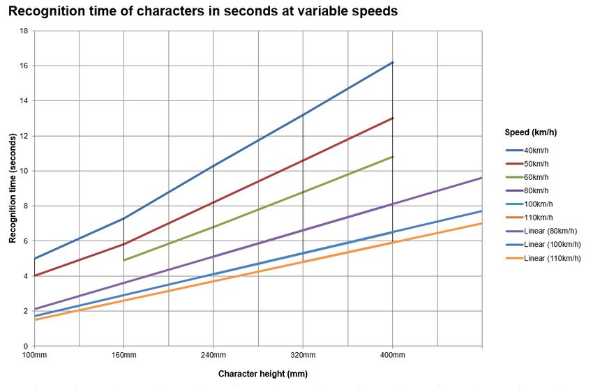
4             DESIGN FOR OPERATION

This section defines the functionality required to achieve successful operation of the intelligent transport
system.

4.1           Character height
Comprehension time will increase with a longer or more complex message. A two-line sign with two pages of
information will take longer to read and assimilate than a four-line sign with the same information displayed on
a single page.

4.1.1         Character height for VMS

Once the number of lines has been determined, the appropriate character height must be considered. The
minimum character height is determined by visibility and the ability of the motorist to read and comprehend the
message. This is a function of:

•     total message size
•     local speed environment
•     lateral position of the VMS.

Drivers approaching the sign at the maximum appropriate/legal approach speed should be able to read the
message(s) for at least:

•     six seconds for a sign with a single page of text
•     at least eight seconds for two-line signs with two pages of messaging
•     10 seconds for four-line signs with two pages of messaging.

Variations on VMS readability, distance and character height are acceptable to Waka Kotahi as long as they
do not compromise safety. Variations shall not conflict with Waka Kotahi signage requirements or standards.

WAKA KOTAHI NZ TRANSPORT AGENCY                                                      VARIABLE MESSAGE SIGNS – FIXED // 13
Once downloaded this document is not controlled and may not be the latest version.
Figure 1. Relationship between character height, travelling speed and recognition (comprehension) time

The table below summarises the recommended minimum character height for HVU and rural environments for
a range of speed environments, and single or dual-lane roadways.

    Version                                                    Minimum character height (mm)

                                  Single lane in direction of travel                 Double lane in direction of travel

    Speed environment
                                  Two-line VMS              Four-line VMS            Two-line VMS       Four-line VMS
    HVU and rural

    Up to 50km/h                  150                       200                      200                200

    51–70km/h                     200                       200*                     300                300

    71–100km/h                    200*                      300                      300**              300**

Table 1. VMS minimum character heights

*In HVU environments with a single lane in direction of travel, where:

•     the annual average daily traffic (AADT) exceeds 20,000 vehicles per day, or
•     15,000 vehicles per day with pronounced peak flows,

the designer should use 300mm character height for four-line signs in 51–70 km/h zones, and for two-line
signs in 71–100km/h zones. Upgrading to a bigger font is strongly advised to improve prominence and
readability in high-volume traffic.

WAKA KOTAHI NZ TRANSPORT AGENCY                                                              VARIABLE MESSAGE SIGNS – FIXED // 14
Once downloaded this document is not controlled and may not be the latest version.
**Sign should be mounted overhead to prevent vehicles in the left lane obscuring the message from those in the right lane. 4.1.2 How to determine character height The legibility distance can be based on character height, multiplied by a factor. This factor is dependent on various environmental and human parameters and is typically given a value in the range between 500–620. The legibility of a font also depends heavily on its design. Standard text fonts are not always suited for a VMS, because the radiation of the light-emitting elements can easily close gaps (in letters such as ‘a’ or ‘e’ etc) that are too small. Recognition time is calculated as the time the driver can read the message while approaching the VMS, and shall meet a range of at least four to six seconds. It is calculated from the vehicle speed and from the legibility distance. Legibility distance is the gap between maximum and minimum legibility distance (ie the distance when the text becomes readable to the distance when the reader is at a point close to the sign when the display is no longer visible). The key factors for maximum legibility distance are the character height, luminance and luminance ratio. The key factors for the minimum legibility distance are the beam width and the mounting position of the VMS. 4.1.2.1 Character height Due to the ability of the human eye to resolve one minute of arc, typically the legibility distance can be calculated with 500–620 times character height. Text written with 300mm character height might be unreadable on distances larger than 150m. To achieve 300m legibility distance, character height of at least 500mm will be necessary. 4.1.2.2 Luminance Due to the fact that luminance is related inverse square to the visibility distance, inter-urban systems always require the highest luminance level L3(*) of EN 12966:2014+A1:2018 Road vertical signs. Variable message traffic signs (EN 12966). This will provide visibility for 300m during normal conditions, with the consequence that from this distance it will be possible to distinguish the ON and OFF state of the sign. Please note that visibility and legibility must not be mixed in this context. In case the message is big enough (see explanations to character height in section 4.1.2.1 above), the message will be also readable, however at 300m distance the apparent luminance is already reduced significantly. 4.1.2.3 Luminance ratio Luminance ratio (also known as contrast) is the fundamental factor for best legibility and describes the ratio of light reflected by environmental illumination and light emitted by light dots. Best example: white text on a bright background will never be legible, even if the text is bright itself. White text on a dark background will always be legible, even if the text is not too bright. Inter-urban systems always require the highest level of luminance ratio R3 of EN 12966. 4.1.2.4 Example site Topological background: • one-lane road each way • 7.6% ascending slope towards the sign WAKA KOTAHI NZ TRANSPORT AGENCY VARIABLE MESSAGE SIGNS – FIXED // 15 Once downloaded this document is not controlled and may not be the latest version.
•     speed 80 km/h
•     mounting height 4m above ground
•     sign size 4.5m x 2.4m (regional type A).

Due to the slope, the mounting height and the height of the sign, the vertical distribution angle shall be at least
–10°. When using beam width classes B1 to B3, the sign should be tilted at least 10 degrees towards the road
in order to achieve an acceptable recognition time. By tilting the sign that much, the sign may not be able to
self-clean (with rain) and there may be a compromise to mechanical stability.

Even if the road has no slope, the minimum legibility distance will not be less than 64m, resulting in a total
length of the legibility distance of only 86m for a 300mm font height. At a speed of 80km/h, the recognition
time will be only 3.9 seconds.

By using B4 in the same conditions and vertical mounting position, recognition time will increase to 5.3
seconds. Considering a slope of 7.6% and tilting the VMS by 3 degrees will achieve the minimum
requirements for recognition time. The wider angle of the B4 means the VMS sight lines are not as sensitive to
the sight lines of the road geometry.

By using B1 to B3 classes, it will be necessary to adjust the signs carefully to the environmental conditions.

Illumination of the environment will not be a topic if the dimming algorithm of the VMS follows the requirements
of EN 12966.

4.2           Selection criteria
4.2.1         Motorway and expressway VMS

•     Motorway and expressway environments are characterised by high volumes, multiple lanes, limited
      access/egress points, and may be subject to congestion. Motorway/expressway VMS generally exhibit the
      following features:
•     large, full matrix-displays capable of:
      −   displaying three lines of at least 18 characters per line with 400mm high text
      −   being read by large volumes of traffic travelling at high speed
•     mounted on overhead gantries to ensure all lanes of a multi-lane environment can view the message. In
      many cases the gantry structures and VMS displays are provided as an integrated package
•     controlled singly or in groups from a remote traffic operations centre (TOC).

4.2.2         Regional VMS

Regional VMS encompass:

•     high-volume urban (HVU) VMS
•     rural VMS.

Regional VMS contrast to motorway/expressway VMS in that they generally:

•     have smaller display sizes with either 300mm or 200mm character height, and either four or two-line
      displays

WAKA KOTAHI NZ TRANSPORT AGENCY                                                      VARIABLE MESSAGE SIGNS – FIXED // 16
Once downloaded this document is not controlled and may not be the latest version.
• are mounted on roadside supports located on the left side of the highway within the road reserve, or
sometimes on private land.
4.2.2.1 High-volume urban VMS
High-volume urban (HVU) VMS have similar functional applications to motorway/expressway VMS but can be
in lower-speed environments that are either single or multi-lane.
The HVU VMS displays may have a smaller character size, and a correspondingly smaller display size based
on road and speed environment. The signs may be positioned in the road reserve, rather than overhead on a
gantry.
4.2.2.2 Rural VMS
The rural VMS application is characterised by significantly larger geographic coverage of the Waka Kotahi
network, and low-volume uncongested roads.
• Located on low-volume roadways typically consisting of one lane in each direction, where motorists can
slow down or pull out of the traffic flow while they consider their response to the VMS message.
• Located in advance of travel decision points.
• May be sited in isolated rural locations where there are minimal competing artificial light sources.
• May be located long distances from critical incident locations, or alternative routes (50–100km is not
uncommon).
• Often have cross-regional function, in that the messages displayed may also have relevance in adjacent
Waka Kotahi region(s).
• The isolated nature of some sites may mean that access to mains power, and fixed line and cellular
communications systems, is not readily available.
4.2.3 Environmental impact and public consultation
Potential costs and delays arising from environmental planning and consent requirements must be considered
when assessing a site, as a large VMS and its support structure may be visually intrusive on the surrounding
area.
As a minimum there is a requirement to consider the need to consult with nearby residents, particularly those
within the LED illumination cone, as the light emitted at night may create adverse effects.
Professional judgment must be exercised as to the likely requirement for a consultation process, and the
range of likely risk to the project in terms of community sustainability, time and cost. Depending on the
outcomes of these considerations, alternative sites may need to be considered.
Refer to section 4.2.4.2 Environmental planning in this document.
4.2.4 Urban design, environmental planning, site services and land issues
4.2.4.1 Urban design requirements
As a signatory to the New Zealand Urban Design Protocol, Waka Kotahi has a role to ensure that VMS
respond to and enhance the environment in which they are placed.
WAKA KOTAHI NZ TRANSPORT AGENCY VARIABLE MESSAGE SIGNS – FIXED // 17
Once downloaded this document is not controlled and may not be the latest version.VMS can potentially add to the visual clutter on the roadside. It is important that VMS are located in relation to
other elements in the visual field of view and that the design of support elements is not neglected and
unrelated to other roadscape elements.
Whilst the design of the VMS is constrained due to safety reasons etc, their size, placement, support
structures and related elements, including rear surfaces, can often be modified to improve the visual quality of
roads and surrounding areas without compromising the sign’s purpose or road user’s safety.
Key strategies and actions for VMS include:
• Design VMS as a vital element of the visual experience of the road and a possible means of reducing the
number of signs.
• Ensure coordination and possible collocation of VMS with other roadscape elements.
• Ensure that the local character of an area is not adversely impacted by unnecessarily large and poorly
located VMS.
• Design support structures and related signage hardware to be integrated with other elements such as
lighting, bridge and guard rails, emergency phones, advertising etc.
• Where VMS are to be located on overbridges, integrate them into the design of these structures if
possible so that they do not appear as add-ons.
• Explore ways to improve the appearance of the rear of the VMS.
4.2.4.2 Environmental planning
4.2.4.2.1 Outline plan
Where VMS are to be located within the boundary of a road designation, the territorial authority (city or district
council) may require an outline plan for the works. It is recommended that discussions be held with the
appropriate territorial authority early in the project to determine their requirements.
Where a road designation is in place, resource consent will not be required to install a VMS. Works in
accordance with the designation will override the District Plan rules. An exception to this would be if there
were conditions on the roading designation relevant to the VMS such as sign height, sign area, character size
or illumination. If a VMS exceeded the relevant conditions, resource consent would be required. However,
conditions on roading designations relating to signage are uncommon and many District Plans provide for
traffic management signs on roads as permitted activities. A check should be made as to whether the sign
would be a permitted activity.
Section 176A of the Resource Management Act 1991 (RMA) requires an outline plan for works that are on
designated land and are in accordance with the designation, to be submitted to the territorial authority. Section
176A (3) of the RMA states:
“An outline plan must show—
(a) the height, shape, and bulk of the public work, project, or work; and
(b) the location on the site of the public work, project, or work; and
(c) the likely finished contour of the site; and
(d) the vehicular access, circulation, and the provision for parking; and
(e) the landscaping proposed; and
(f) any other matters to avoid, remedy, or mitigate any adverse effects on the environment.”
WAKA KOTAHI NZ TRANSPORT AGENCY VARIABLE MESSAGE SIGNS – FIXED // 18
Once downloaded this document is not controlled and may not be the latest version.An outline plan for VMS need only include the information listed above, which is relevant to the particular
proposal.
Territorial authorities do not have the discretion to approve or decline an outline plan. Their sole discretion is to
request changes to an outline plan prior to commencement of the work. The authority responsible for the road
designation, ie Waka Kotahi, may then accept or reject the recommendation of the territorial authority in full or
in part.
In the early discussion with the territorial authority it would be appropriate to enquire whether they require an
outline plan of works. Section 176A (2) of the RMA lists the following exceptions to the general rule:
“An outline plan need not be submitted to the territorial authority if—
(a) the proposed public work, project, or work has been otherwise approved under this Act; or
(b) the details of the proposed public work, project, or work, as referred to in subsection (3), are incorporated
into the designation; or
(c) the territorial authority waives the requirement for an outline plan.”
In the past a number of territorial authorities have, upon enquiry from the road authority or its agent, not
required an outline plan of works given the minor nature of the VMS.
4.2.4.2.2 Resource consents
Where VMS are to be located outside the boundary of a road designation, a land use consent may be required
from the territorial authority. An assessment under the relevant rules of the District Plan will be necessary to
determine whether the VMS needs a resource consent.
4.2.4.2.3 Assessments of environmental effects
Where Waka Kotahi is required to apply for a resource consent to locate a VMS, an assessment of
environmental effects must be undertaken. This would require a more extensive and detailed assessment than
for an outline plan.
The actual or potential effects being assessed will need to be tailored to the circumstances of the VMS
proposed. In most situations, the main effects that will be considered are visual and traffic safety effects. The
visual effects could include matters such as sign height, size, location or amenity. The traffic safety effects
could include the benefits to traffic safety as a result of the sign or any potential driver distraction
considerations. Site, location and sign design plans and information on how the sign will be operated and
serviced should be included with the application. It would also be helpful to include visual imagery that
demonstrates the appearance of the sign and the highly directional nature and narrow illumination cone of the
display elements.
Where a VMS requires a resource consent, written approval to the proposal from the affected party, ie the
landowner concerned, will be necessary. It is important to note that written approval of the VMS cannot be
subject to conditions. The affected party either approves or does not approve the VMS. If the affected party
has particular conditions they would like addressed, these should be incorporated into the proposal or through
private contract with Waka Kotahi. If the resource consent application requires amendment due to the affected
party’s concerns, then the application should note that the proposal has been amended to address the
WAKA KOTAHI NZ TRANSPORT AGENCY VARIABLE MESSAGE SIGNS – FIXED // 19
Once downloaded this document is not controlled and may not be the latest version.concerns of the affected party and that the affected party has provided written approval to the amended
proposal.
4.2.5 Land issues
There are normally distinct advantages in having:
• the VMS site, and
• the line of clear sight to the VMS sign over the entire legibility distance, and
• trenched or overhead services to the sign
completely within the legal boundary of the road reserve or land owned by the Crown, to avoid landowner
negotiations, compensation, legal issues and potential delays.
This section is intended to flag the importance of ensuring any agreements with landowners are placed on a
formal legal basis if encroachment into neighbouring land is going to occur. It does not address details of such
legal instruments as Easements, Land Plans, Land Entry Agreements, Full and Final Agreements, and
compensation for landowners, which may be required if encroachment occurs. For specialist advice, the Waka
Kotahi Property Consultant should be approached.
4.2.6 Communications to site
A communications link is required to connect the VMS to the Waka Kotahi national control system.
In urban, motorway and expressway locations, there are a range of communications options that can be
utilised, including:
• use of any existing Waka Kotahi communications network
• leased lines from commercial providers (ADSL)
• mobile communications such as GSM.
For regional VMS sites, options include:
• Telecommunications copper line connecting to ADSL (broadband) – preferred option
• mobile communication such as GSM. Waka Kotahi has national communications agreements in place
with a commercial provider.
Depending on the communication system selected, there may be a need to arrange cabling/trenching to the
site. As with the power requirements, consideration should be given to tasking a telecommunications
contractor with arranging cabling to the site. With regional VMS, this is normally arranged by the Waka Kotahi
National Office.
Note that consent from Waka Kotahi is required before cabling installation is undertaken in the road reserve.
Where the VMS is connected to mains power and a copper communication cable, there must be appropriate
separation. Where power and communication cables are laid in the same trench for up to 200m, separation of
>200mm is required.
WAKA KOTAHI NZ TRANSPORT AGENCY VARIABLE MESSAGE SIGNS – FIXED // 20
Once downloaded this document is not controlled and may not be the latest version.4.2.7 VMS site selection criteria VMS site selection must consider many interrelated factors. There is a close relationship between site selection and selection of the sign size/display technology. Site considerations influence the selection of sign and technology, and sign constraints influence the choice of site. The strategic location and anticipated simultaneous message suite determine the number of characters per line and lines for each sign. The character height is subsequently decided during site selection based on the speed environment and other factors at the proposed site. 4.2.7.1 Strategic locations – an introduction VMS projects are generally justified on the benefits of establishing a sign or signs at strategic locations or nodes on the state highway network. At a macro level, the site selection process must identify all potentially suitable sections of highway for siting VMS to ensure that viable options are not excluded from subsequent consideration. The Roadrunner tool, which provides a ‘motorist’s-eye view’ of the state highway system, is an extremely useful tool to identify potential sites rapidly and safely before actual site visits are undertaken. The VMS must be positioned above or to the left of the approaching motorist. In virtually all situations, it is considered unsafe to position a VMS on the right-hand side of approaching traffic because it may confuse motorists’ point of reference under night-time conditions and lead to a head-on collision. 4.2.7.2 Minimum distance from key intersections If the VMS is intended to advise route diversions, the sign shall be located sufficiently in advance of the alternative route intersection to allow the road user to assimilate the message and react accordingly, including changing lanes if necessary. Motorway/expressway VMS should be placed a minimum distance of 1500m prior to the exit/diversion point. This distance provides the motorist with roughly 50–60 seconds from the time they have read the message until they reach the access/diversion point. In practice, this is difficult to achieve in urban areas where interchanges are closely spaced. If the motorway/expressway has two or three lanes in the direction the VMS is indicating, this can be reduced to a minimum of 800m. Alternatively, if two exits are closely spaced, the VMS can be in advance of the first exit. No motorway/expressway VMS shall be installed within 300m of the end of an upstream merge taper. On high-volume urban (HVU) roads, the distance is dependent on considerations such as the speed limit, local factors and right-of-way constraints. On a rural single-lane roadway, with no need to change lanes, but acknowledging the complexity of some decisions and the route choices, a distance equating to at least 1000 metres in a 100km/h zone, or a proportionally reduced distance in lower-speed zones, is suggested. If a rural VMS with low traffic volumes (eg 2000 AADT) may display a message advising motorists to turn back, consideration should be given to choosing a site that has a suitable pullover/turning area just after the sign for travellers to turn around. WAKA KOTAHI NZ TRANSPORT AGENCY VARIABLE MESSAGE SIGNS – FIXED // 21 Once downloaded this document is not controlled and may not be the latest version.
With higher traffic volumes in a high-speed environment, a level (~10,000 AADT) is reached where pulling
over or turning around is unsafe. Under normal circumstances, the VMS will be placed in advance of the
decision/alternative route point, so turning around will be unnecessary, but professional judgement should be
exercised as to whether pullover or turning areas are appropriate.

4.2.7.3       Influence of message suite on sign configuration

The number of locations or routes covered by the sign, and range of messages required to be displayed at any
one time, influence the selection of sign. This is particularly true in the rural context where a choice is made
between two- or four-line signs. The interaction between likely message complexity, speed environment and
character height must reach a mutually compatible solution. Character height in turn determines sign width. It
is therefore necessary to establish the maximum likely range of messages to be displayed at any one time and
understand sign type options before undertaking detailed site selection. Refer to section 4.1 Character height
in this document.

4.2.7.4       Speed environment and character height

Refer to section 4.1 Character height in this document. The minimum character heights are based on table 1
of TD 33/05 UK Design manual (TD 33/05).

The standard categories of character height for Waka Kotahi VMS are:

•    400mm for motorways and expressways
•    300mm and 200mm for HVU and rural, dependent on message size and speed environment.

The character height determines the width of regional signs, and hence influences site selection, ie:

•    standard regional VMS with 300mm character height is ~5m overall width
•    standard regional VMS with 200mm character height is ~3.3m overall width.

4.2.7.5       Clear sight distance

In motorway/expressway and HVU settings there are typically many other signs and distractions that compete
for motorists’ attention. Visibility and impact, proportional to the environmental context, are particularly
important considerations of site selection.

For rural VMS, the designer should look for sites that allow motorists clear sight distance to the sign of at least
375m for 300mm character height, and at least 250m for 200mm character height, when travelling at 100km/h.
In lower-speed environments the distances can be reduced proportionally.

Ensure that roadside trees or other structures will not obscure the sign. Ensure that requirements for trimming
or other activities to maintain clear line of sight in the foreseeable future can be legally enforced.

4.2.7.6       Sign orientation requirements

The VMS shall be orientated such that it complies with the relevant beam-width class specified in EN 12966.

4.2.7.7       Road angle vertical plane

The designer must take into account the viewing angle of the LEDs when considering a site.

WAKA KOTAHI NZ TRANSPORT AGENCY                                                      VARIABLE MESSAGE SIGNS – FIXED // 22
Once downloaded this document is not controlled and may not be the latest version.
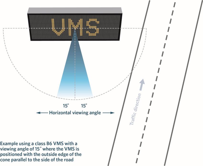
Correct alignment is important to ensure approaching motorists will remain within the cone of illumination for
as long as possible. The ability to optimally align the VMS in the vertical plane must be considered when the
approach is up a steep hill, or if the VMS is unusually high above the road.

4.2.7.8       Road angle horizontal plane

If possible, avoid positioning the VMS directly in front of a rising or setting sun as this may significantly reduce
its effective visibility. Similarly, reflections of the sun on the display face may reduce its legibility even with an
anti-phantom display. Note the seasonal variation between the intersection of the arcs of the (higher) summer
sun and the (lower) winter sun, and the horizon.

Where these display visibility factors cannot be mitigated, eg by taking advantage of a natural backdrop of a
hill or trees, or a downhill slope, then the use of a hood or louvres should be considered to shield the display.

In certain situations, eg where traffic is angling across, rather than directly approaching the sign, it may be
necessary to specify LEDs with a wider non-standard illumination cone.

Regional VMS are normally mounted to the side of the roadway on the left-hand side of approaching traffic
where there is a single approaching lane. For a straight approach, the right edge of the cone of visibility should
be aligned down the road reserve parallel with the road, as illustrated in figure 2 below.

WAKA KOTAHI NZ TRANSPORT AGENCY                                                       VARIABLE MESSAGE SIGNS – FIXED // 23
Once downloaded this document is not controlled and may not be the latest version.
Figure 2: Cone of visibility alignment for a straight approach to a roadside sign

For VMS mounted some distance beyond a left or right-hand curve, alignment should maximise the time that
travellers remain within the cone of visibility, as illustrated in figure 2 and detailed in the latest version of. ITS
design standard: Civil and structural requirements.

The horizontal alignments for straight and curved approaches are illustrated in figure 2 and detailed in the
latest version of ITS design standard: Civil and structural requirements.

For curved approaches, the VMS must be aligned to ensure:

•    at the maximum reading distance, the inside edge of the curve is within the cone of visibility
•    approaching the VMS, the outside edge of the curve remains within the cone of visibility for as long as
     possible.

For further guidance, refer to EN 12966 section N.4.3.

See the latest version of ITS design standard: Civil and structural, for these diagrams:

•    Optimum alignment for regional VMS on roadside support structure
•    Optimum alignment for motorway VMS on overhead gantry.

WAKA KOTAHI NZ TRANSPORT AGENCY                                                       VARIABLE MESSAGE SIGNS – FIXED // 24
Once downloaded this document is not controlled and may not be the latest version.
4.2.7.9 Road geometry Avoid positioning a VMS immediately before a sharp bend, blind crest or intersection, where the VMS may distract attention at a critical moment and could lead to loss of driver control. Also, the VMS must not be positioned where the display may be seen from a neighbouring road if this will result in motorists receiving confusing or conflicting information. 4.2.7.10 Presence of other signage VMS should not compete with other existing signs and/or strong light-emitting sources or interfere with traffic control devices. The designer must make an inventory of all signs and traffic control devices both proceeding and beyond the potential site. Based on this inventory, existing signs may need to be moved to accommodate the VMS placement. VMS and static signage may be co-located on a gantry structure. MOTSAM requires different signs to be located a minimum of (0.6V85) apart, where V85 is the 85th percentile speed of traffic, in km/h, at the sign location. 4.2.7.11 Width and boundary of road reserve Having established the space requirements for the VMS and any barrier protection, it is essential to identify the position of the legal boundary in relation to the boundary fence or other indication of the edge of the road reserve. The position of the boundary fence and the legal boundary of the road reserve may not coincide. It may be enough to overlay boundary plans on an aerial photo, or a survey may be required to establish the legal boundary. 4.2.7.12 Access to mains power Assuming the VMS will be mains powered, it is necessary to estimate the cost of supplying power to the site. If there is not an existing power supply nearby, or if a line must be run over private property, the cost and delay factors can be significant. If the power supply must come from the other side of the roadway, trenching across the state highway is not acceptable, an aerial cable may also not be acceptable, and thrust boring may be the only option. 4.2.7.13 Communications coverage Depending on the communications options being considered, it may be necessary to establish the location of the nearest suitable hardwiring, or the strength of the cellular coverage at the proposed sites. The installation (capital) cost, operating cost and fitness for purpose of the communications options must be established. WAKA KOTAHI NZ TRANSPORT AGENCY VARIABLE MESSAGE SIGNS – FIXED // 25 Once downloaded this document is not controlled and may not be the latest version.
You can also read