Manual - Expert Power Control 8291 - Gude Systems
←
→
Page content transcription
If your browser does not render page correctly, please read the page content below
Manual

 Expert Power Control 8291

                             © 2021 GUDE Systems GmbH
                                         Manual Ver. 1.0.2
                                    from Firmware Ver. 1.0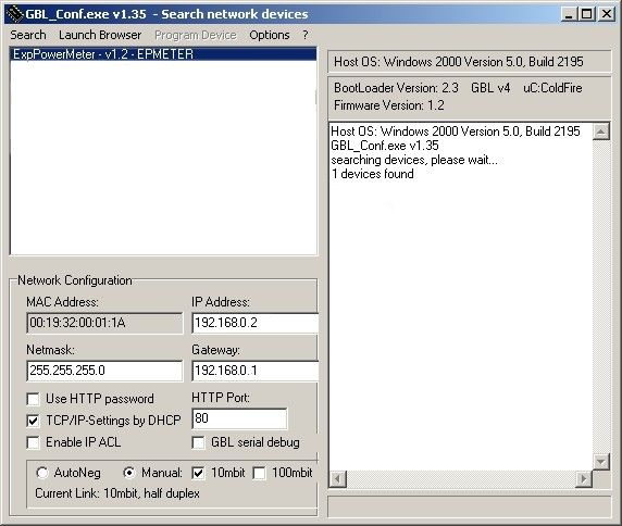
2

Expert Power Control 8291   © 2021 GUDE Systems GmbH

Table of contents

1.       Device Description                                                                                                                      5
   1.1          Security Advice ....................................................................................................... 6
   1.2          Content of Delivery ................................................................................................. 6
   1.3          Description ............................................................................................................. 6
   1.4          Installation ............................................................................................................. 7
   1.5          Structure EPC 8291 ................................................................................................. 9
   1.6     Technical Specifications ........................................................................................ 11
     1.6.1     Electrical Measurement ......................................................................................... 12
   1.7     Sensor .................................................................................................................. 13

2.       Operating                                                                                                                             16
   2.1          Operating the device directly ................................................................................ 17
   2.2          Control Panel ........................................................................................................ 17
   2.3     Maintenance ........................................................................................................ 19
     2.3.1    Maintenance Page ................................................................................................. 21
     2.3.2    Configuration Management .................................................................................. 22
     2.3.3    Bootloader Activation ............................................................................................ 23

3.       Configuration                                                                                                                         26
   3.1          Power Ports .......................................................................................................... 27
     3.1.1          Watchdog ............................................................................................................... 28
   3.2          Ethernet ............................................................................................................... 30
     3.2.1          IP Address ............................................................................................................... 30
     3.2.2          IP ACL ..................................................................................................................... 31
     3.2.3          HTTP ....................................................................................................................... 32
   3.3          Protocols .............................................................................................................. 33
     3.3.1          Console ................................................................................................................... 34
     3.3.2          Syslog ..................................................................................................................... 36
     3.3.3          SNMP ...................................................................................................................... 36
     3.3.4          Radius ..................................................................................................................... 38
     3.3.5          Modbus TCP ........................................................................................................... 39
   3.4          Clock ..................................................................................................................... 39
     3.4.1          NTP ......................................................................................................................... 40
     3.4.2          Timer ...................................................................................................................... 41
     3.4.3          Timer Configuration ............................................................................................... 41
   3.5          Sensors ................................................................................................................. 47
     3.5.1          Port Switching ........................................................................................................ 49
   3.6          E-Mail ................................................................................................................... 50
   3.7          Front Panel ........................................................................................................... 51
   3.8          Fan ....................................................................................................................... 51

     3

Expert Power Control 8291                                                                                                       © 2021 GUDE Systems GmbH
Table of contents

4.       Specifications                                                                                                                  52
   4.1          IP ACL ................................................................................................................... 53
   4.2          IPv6 ...................................................................................................................... 53
   4.3          Radius ................................................................................................................... 54
   4.4          Automated Access ................................................................................................ 54
   4.5     SNMP ................................................................................................................... 55
     4.5.1      Device MIB 8291 .................................................................................................... 57
   4.6     SSL ........................................................................................................................ 60
   4.7     Console ................................................................................................................. 61
     4.7.1    SSH ......................................................................................................................... 65
     4.7.2    Push Messages ....................................................................................................... 66
     4.7.3    Console Cmd 8291 ................................................................................................. 66
     4.7.4    Serial Console ......................................................................................................... 76
   4.8     Modbus TCP ......................................................................................................... 76
   4.9          Messages .............................................................................................................. 81

5.       Support                                                                                                                         83
   5.1          Data Security ........................................................................................................ 84
   5.2          Contact ................................................................................................................. 84
   5.3          Declaration of Conformity ..................................................................................... 85
   5.4          FAQ ...................................................................................................................... 85

Index                                                                                                                                    87

                                                                                                                                           4

Expert Power Control 8291                                                                                                  © 2021 GUDE Systems GmbH
Device Description
Device Description

1           Device Description
1.1         Security Advice

            · The device must be installed only by qualified personnel according to the following
              installation and operating instructions. The manufacturer does not accept responsib-
              ility in case of improper use of the device and particularly any use of equipment that
              may cause personal injury or material damage.
            · The device contains no user-maintainable parts. All maintenance has to be per-
              formed by factory trained service personnel.
            · This device contains potentially hazardous voltages and should not be opened or
              disassembled.
            · The device can be connected only to 100 - 240 V AC (50 - 60 Hz) power supply
              sockets.
            · The used power cords, plugs and sockets have to be in good condition. Always con-
              nect the device to properly grounded power sockets.
            · To disconnect the appliance quickly and safely from the power supply, the outlet
              supplying the appliance with power must be easily accessible.
            · This equipment is designed for indoor use only. It must not be used in condensing or
              excessively hot environments.
            · Please also observe the other instructions in the instructions for proper handling of
              the device.
            · Because of safety and approval issues it is not allowed to modify the device without
              our permission.
            · The device is NOT a toy. It has to be used or stored out of range of children.
            · Care about packaging material. Plastics has to be stored out of range of children.
              Please recycle the packaging materials.
            · In case of further questions, about installation, operation or usage of the device,
              which are not clear after reading the manual, please do not hesitate to ask our sup-
              port team.
            · Please, never leave connected equipment unattended, that can cause damage.
            · Only connect electrical devices that do not have a limited duty cycle. This means that
              in the event of a fault, all connected electrical devices must be able to withstand con-
              tinuous activation without causing damage.

1.2         Content of Delivery

            The package includes:

            · Expert Power Control 8291
            · 1 x Power Supply cable (IEC C19, max. 16 A)
            · Quick Start Guide

1.3         Description

            The Expert Power Control 8291-1 has 17 DC switchable power outlets with voltages
            of 24 V, 12 V and 5 V and 4 AC (IEC C13, max. 10A) switchable power outlets

            · 21 Power Ports individually switchable directly on the device
            · Integrated power supply unit (max. 300 W) with active power factor correction (PFC)

                                                                                                                6

Expert Power Control 8291                                                                          © 2021 GUDE Systems GmbH
Device Description
· Power monitoring of 5 V, 12 V and 24 V (Bank A-D)
· Maximum available DC current per port: max. 4 A
· Current segmentation per bank: 5 V: max. 8,8 A, 12 V: max. 6 A, 24 V: max. 12,5 A
· AC: Metering of energy, current, power factor, phase angle, frequency, voltage and
active / apparent / reactive power
· AC: Residual current metering type A
· A clearly visible LED display for port status, total current,
· Integrated overvoltage protection (SPD) type 3
· Each outlet protected by eFuses in case of short circuits
· 2 interfaces for optional sensors for environmental monitoring (temperature, humidity
and air pressure)
· RJ45 network connection and RS232 interface
· Console commands via SSH, Telnet and serial interface
· SSH support with public key and passwords
· Individually parameterisable switch-on delay of all outputs
· Programmable timetables and turn-on/turn-off sequences
· Individually adjustable watchdog for each output, which switches depending on ac-
cessibility (network ping)
· Dual TCP/IP stack with IPv4 and IPv6 support (IPv6-ready)
· Control and monitoring of the device via Ethernet with an integrated web server with
SSL encryption (TLS 1.1, 1.2, 1.3)
· Control and configuration with CGI parameters and JSON messages via HTTP
(REST API)
· SNMP (v1, v2c and v3, traps)
· Modbus TCP support
· Radius support
· Generation of messages (e-mail, syslog and SNMP traps) and switching of relays
depending on sensor measurement limits
· Firmware update during operation via Ethernet possible
· Encrypted e-mails (SSL, STARTTLS)
· Access protection through IP access control
· Low own consumption
· Developed and produced in Germany
1.4 Installation
Anzeige pro Bank
1. LED indicators (5V, 12V, 24V, 230V) for bank voltage display
2. LED indicator (flash) for Over Voltage Protection (green - surge protection is active,
red - inactive)
3. 21 plain text displays (on/off) for the state of the outputs (Bank A to Bank E)
4. 2 x 7-segment display for measured values
5. Status LED
7
Expert Power Control 8291 © 2021 GUDE Systems GmbHDevice Description
6. Select button
7. Ok button
8. Ethernet connector (RJ45)
9. 2 x External sensor connectors (RJ45)
10. RS232 connector
11. Mains supply (IEC C20, max.16A)
12. 4 x Load outputs Bank E (IEC C13, max. 16A)
13. 4 x Industrial terminal 2-pole (Bank D)
14. 4 x Industrial terminal 2-pole (Bank C)
15. 4 x Industrial terminal 2-pole (Bank B)
16. 5 x Industrial terminal 2-pole (Bank A)
17. 5 x USB socket Type A (Bank A)
18. 3 x LED indicators 12V / 24V selected
The USB ports are for power supply only, no data communication takes place.
Start-up the device
· Connect the power cord (IEC C19, max. 16A) to the mains supply. The cable con-
nectors are secured as regards their type against unintentional loosening. They must
be inserted up to the stop, otherwise there is no secure connection. The plug must
not wobble in the socket, or there is no tight connection.
· Plug the network cable into the Ethernet socket (RJ45).
· If required, setup a serial connection to the RS232 port.
· Insert the optional external sensors into the sensor connectors.
· Connect the consumers with the load outputs (IEC C13, max. 10A).
· Connect the consumers with the Industrial terminal or USB sockets.
8
Expert Power Control 8291 © 2021 GUDE Systems GmbHDevice Description
1.5 Structure EPC 8291
The Expert Power Control 8291-1 has 17 x DC switchable outputs with voltages of
12V, 24V and 5V as well as 4 x AC switchable 230V outputs. The outputs are divided
into 5 different banks:
· Bank A with 5V (max. 8.8 A)
· Bank B with 12V (max. 6.0 A) or 24V (max. 12.5 A)
· Bank C with 12V (max. 6.0 A) or 24V (max. 12.5 A)
· Bank D with 12V (max. 6.0 A) or 24V (max. 12.5 A)
· Bank E with 230V (max. 10 A)
The voltage selection (12V or 24V) of the banks B to D is indicated by LEDs on the
front panel and on the back.
Voltage sources in the EPC 8291-1
The 230V mains voltage feeds the built-in 24V power supply unit (300 W) of the
device. On the web page (Control Panel) the measurements of the DC voltage sources
S1 to S5 are displayed. Here corresponds:
· S1 - 5V DC (max. 8.8 A) for Bank A fed from 24V
· S2 - 12V DC (max. 6.0 A) for bank B fed from 24V
· S3 - 12V DC (max. 6.0 A) for Bank C fed from 24V
· S4 - 12V DC (max. 6.0 A) for Bank D powered from 24V
· S5 - 24V DC (max. 12.5 A) fed from 230V mains voltage
9
Expert Power Control 8291 © 2021 GUDE Systems GmbHDevice Description
In this example you can see that the voltage source S1 (bank A) is fed by the source
S5 (24V power supply). The consumption at S1 is also reflected at S5.
Measuring points of the voltage sources
The device has a current and voltage measurement at the following locations in the
device:
· Bank A 5V DC (Bank monitor) display on the website Bank A
· Bank B 12V / 24V DC (Bank monitor) Display on the website Bank B
· Bank C 12V / 24V DC (Bank monitor) Display on the website Bank C
· Bank D 12V / 24V DC (Bank monitor) Display on the website Bank D
· 24V power supply (Supply monitor) Display on the website as "S5"
· 230V power supply (Energy monitor & RCM type A) on the website as "L1 Meter12
Critical voltage and current values
If the voltage measurement falls below minimum values, the voltage indicator LED on
the front panel changes from green to red. If the current of a bank or 24V power supply
exceeds a critical value, the voltage indicator LED flashes.
Error case 5V 12V 24V 230V
Voltage undershot (red < 4,75V < 11,4V < 22,8V < 80V
LED)
Current exceeded (flash- > 8,8 A > 6,0 A > 12,5 A > 16 A
ing LED)
Here the voltage at bank D has fallen below 11.4V.
Use of eFuses
In the device, the DC power sources are protected by resettable electronic fuses
(eFuses). These fuses are triggered by short circuit or overload. If an eFuse is
triggered, the output is switched off. The device then also automatically switches off
the port (front LEDs go from "on" to "off"). When the port is turned on again, the eFuse
is reset and the output will operate normally until another short circuit or overload oc-
10
Expert Power Control 8291 © 2021 GUDE Systems GmbHDevice Description
curs. Triggering of an eFuse is indicated on the front panel LEDs by a flashing green
triangle above a port number. The following states exist for an eFuse:
State Number Web Icon Frontpanel LED
switched off (Ok) 0
switched on (Ok) 1
eFuse triggered (Error 1) 2 flashing triangle
External voltage source (Er- 3 flashing triangle
ror 2)
The numbers (0 - 3) of eFuses are returned by console commands, SNMP and Mod-
bus TCP as eFuse state description.
Operating external voltage sources at the outputs of the EPC 8291-1 can cause
damage to the device.
In this example an overload has occurred on port 2 of bank A.
Overvoltage Protection
The device has a type 3 overvoltage protection. The status of which is indicated by a
green and a red flash on the front panel. A green flash indicates that the protection is
operational, a red flash indicates that the overvoltage protection is out of order. In addi-
tion, the status of the surge protection cant be determined via data communication with
the device. Each surge protector is designed to discharge a virtually unlimited number
of surge pulses in normal installation environments. In an environment with many high-
energy surge pulses, aging of the surge protection element can lead to a permanent
failure of the function.
The surge protection function can only be restored by the manufacturer of the
device. Normally, the device will continue to operate even after the failure of the pro-
tective function.
Signalling via e-mail, syslog or SNMP trap is only done once during operation, ex-
actly at the moment when the protection fails. In addition, a message is generated
when the device is switched on if the surge protection is not operational.
1.6 Technical Specifications
Interfaces 1 x Ethernet port (RJ45)
1 x Serial connector (D-SUB, RS232)
11
Expert Power Control 8291 © 2021 GUDE Systems GmbHDevice Description
1 x Mains supply (IEC C20, max.16 A)
5 x USB socket Type A (5V, max. 3.5 A)
5 x DC outputs (5V, max. 3,5 A)
12 x DC outputs (12V / 24V, max. 4 A)
4 x Load outputs (IEC C13, max. 16 A)
2 x RJ45 for external sensor
Network connectivity 10/100 MBit/s Ethernet RJ45
Protocols TCP/IP, HTTP/HTTPS, SNMP
v1/v2c/v3, SNMP traps,
Syslog, E-Mail (SMTP), Telnet, SSH,
Modbus TCP
Power Supply internal power supply (240V AC / -15% /
+10%)
Overvoltage Protection Type 3
Environment
· Operating temperature 0°C - 50 °C
· Storage temperature -20°C - 70 °C
· Humidity 0% - 95% (non-condensing)
Case powder coated, galvanized steel sheet
Measurements 19" (inches), 1 Rack Unit, (Depth 240
mm)
Weight approx. 4.4 kg
Plug for DC switching outputs Industrial terminal 2-pole - AK1550/2-
3.5-GREEN
1.6.1 Electrical Measurement
typical fault tolerances for Ta=25°C, I=1Arms...16Arms, Un=90Vrms...265Vrms
Electrical Measurement Specification DC
Category Range Unit Resolu- Inaccuracy
tion (typical)
Voltage 90-265 V 0.01 < 1%
Current 0 - 16 A 0.001 < 1.5%
Frequency 45-65 Hz 0.01 < 0.03%
Phase -180 - +180 ° 0.1 < 1%
Active power 0 - 4000 W 1 < 1.5%
Reactive power 0 - 4000 Var 1 < 1.5%
Apparent power 0 - 4000 VA 1 < 1.5%
Power factor 0-1 - 0.01 < 3%
Energy Counter
Active Energy 9.999.999,999 kWh 0.001 < 1.5%
(total)
Active Energy 9.999.999,999 kWh 0.001 < 1.5%
(temporary)
12
Expert Power Control 8291 © 2021 GUDE Systems GmbHDevice Description
Measurement accuracy DC
Voltage internal
better ± 3% of measured value ± 0.1V
sources S1...S5
Current Bank A...D + S5
better ± 3% of measured value ± 0.1A
(pure resistive loads)
1.7 Sensor
Two external sensors can be connected to the Expert Power Control 8291-1. The fol-
lowing sensors are currently available
Humidity/Temperature Sensor 7102 (End-of-Life)
Cable length
Connector RJ45
temperature range -20°C to +80°C, ±0,5°C (maximum) and ±0,3°C (typical)
air humidity range 0-100%, ±3% (maximum) and ±2% (typical)
(non-condensing))
13
Expert Power Control 8291 © 2021 GUDE Systems GmbHDevice Description
Product Name 7101 7104-1 7105-1 7106-1
Calibrated - 7104-2 7105-2 7106-2
Sensor
Cable length
Connector RJ45 RJ45 RJ45 RJ45
temperature range -20°C to +80°C at -20°C to +80°C at -20°C to +80°C at -20°C to +80°C at
±2°C (maximum) ±2°C (maximum) ±2°C (maximum) ±2°C (maximum)
and ±1°C (typical) and ±1°C (typical) and ±1°C (typical) and ±1°C (typical)
air humidity range - - 0-100%, ±3% 0-100%, ±3%
(non-condensing) (maximum) and (maximum) and
±2% (typical) ±2% (typical)
air pressure range - - - ± 1 hPa (typical)
(full) at 300 ... 1100
hPa, 0 ... +40 °C
air pressure range - - - ± 1.7 hPa (typical)
(ext) at 300 ... 1100
hPa, -20 ... 0 °C
Protection IP68 - - -
Product Name 7201 7202
Cable length - -
Connector RJ45 RJ45
temperature range -20°C to +80°C at ±2°C (max- -20°C to +80°C at ±2°C (max-
imum) and ±1°C (typical) imum) and ±1°C (typical)
air humidity range - 0-100%, ±3% (maximum) and
(non-condensing) ±2% (typical)
The sensors are automatically detected after connect. This is indicated by the green
LED on the sensor port that is lit permanently. The sensor values are displayed at
the "Control Panel" web page:
A click on the link in the "Name" column opens the display of the Min and Max values.
The values in a column can be reset using the "Reset" button. The "Reset" button in
the name column deletes all stored Min and Max values.
14
Expert Power Control 8291 © 2021 GUDE Systems GmbHDevice Description 15 Expert Power Control 8291 © 2021 GUDE Systems GmbH
Operating
Operating

2           Operating
2.1         Operating the device directly

            Port Switching
            The current status of the output is indicated by the color of the LED. Red indicates that
            the output is off, green shows that the output is on. On the device are the buttons "se-
            lect" and "ok". If you press "select", you can select the following modes one by one:

            1. At first, all LEDs flash green. If you press the "Ok" button for 4 seconds, all ports
               are switched on. (If all ports are switched on, this is skipped).
            2. After that, all LEDs flash red. If you hold the "Ok" button for 4 seconds, all ports will
               be switched off. (If all ports are switched off, this will be skipped).
            3. If you press "Select" again, the LED for the first output starts blinking, i.e. the output
               is selected. Press "Select" again to select the next output. If you keep the "Ok" but-
               ton pressed for one second, the state of the selected output will be toggled.

                You can switch off in the front panel   51   configuration that all ports with the modes
            1 and 2 can be switched by pushbutton.

            Display Information
            If no port is selected manually, repeatedly pressing the "ok" button will show the IP-ad-
            dress and the values of the external sensors on the display.

            Status-LED
            The Status LED shows the different states of the device:

            · red: The device is not connected to the Ethernet.
            · orange: The device is connected to the Ethernet and waits for data from the DHCP
              server.
            · green: The device is connected to the Ethernet and the TCP/IP settings are alloc-
              ated.
            · periodic blinking: The device is in Bootloader mode.

2.2         Control Panel

            Access the web interface: http://"IP-address" and log-in.

  17

Expert Power Control 8291                                                                              © 2021 GUDE Systems GmbH
Operating
The website provides an overview of the switching status and shows the measured val-
ues of the current banks A to E. If you click on a single port, the buttons appear to con-
trol the port:
The port icon is green when a port is on or red when it is off. The output can be
switched manually using the "On" and "Off" buttons. If the output is switched on, it can
be switched off by pressing "Reset" until it switches on again after a delay. This delay
time is determined by the parameter Reset Duration, which is described in the chapter
"Configuration - Power Ports 27 ". The "Close" button makes the buttons disappear
again. An additional small clock symbol indicates that a timer is active. Timers are ac-
tivated by switch-on delay, reset or batch mode. A flash on the icon indicates an error
condition of the eFuse.
An activated Watchdog is represented by an eye icon. An "X" means, that the address
that should be observed, could not be resolved. Two circular arrows show a booting
status.
Batchmode
Each individual port can be set for a selectable period of time to the state "switch on"
or "switch off". After the selected time they are automatically switched to the second
preselected state.
Optionally the device can be switched via a Perl script or external tools like wget. More
information is available on our support wiki at www.gude.info/wiki.
18
Expert Power Control 8291 © 2021 GUDE Systems GmbHOperating
Measured values mains connection and power sources
For mains connection, current, voltage, phase angle, power factor, frequency, active,
apparent, reactive and residual power are measured.
Display of voltage and current of each source S1 to S5.
2.3 Maintenance
The actual device generation with IPv6 and SSL allows all maintenance functions in
the web interface to be carried out on the Maintenance Page 21 .
Maintenance in the web interface
The following functions are available from the maintenance web page:
· Firmware Update
· Change the SSL certificate
· Load and save the configuration
· Restart the device
· Factory Reset
· Jump into the Bootloader
· Delete the DNS cache
Upload Firmware, Certificate or Configuration
On the Maintenance Page 21 , select the required file with "Browse .." in the sections
"Firmware Update", "SSL Certificate Upload" or "Config Import File Upload" and press
"Upload". The file is now transferred to the update area of the device and the contents
are checked. Only now, pressing the "Apply" button will permanently update the data,
or abort with "Cancel".
Only one upload function can be initiated with a reboot, eg. you cannot transmit
firmware and configuration at the same time.
If after a firmware update, the web page is not displayed correctly anymore, this
19
Expert Power Control 8291 © 2021 GUDE Systems GmbHOperating
may be related to the interaction of Javascript with an outdated browser cache. If a
Ctrl-F5 does not help, it is recommended that you manually delete the cache in the
browser options. Alternatively, you can test start the browser in "private mode".
During a firmware update, old data formats are sometimes converted to new struc-
tures. If an older firmware is newly installed, the configuration data and the energy
meters may be lost! If the device then does not run correctly, please restore the factory
settings (e.g. from the Maintenance Page 21 ).
Actions in Bootloader mode
If the web interface of the device is no longer accessible, the device can be put into
Bootloader mode (see chapter Bootloader activation 23 ). The following functions can
be executed using the GBL_Conf.exe application:
· Set IPv4 address, net-mask and gateway
· Turn HTTP password on and off
· Turn IP-ACL on and off
· Factory Reset
· Jump into the bootloader (can be switched on and off)
· Restart the device
For devices with relays, entering or exiting the bootloader mode does not change
the state of the relays as long as the operating voltage is maintained.
The GBL_Conf.exe program is available free of charge on our website www.gude.info
and can also be found on the enclosed CD-ROM.
Interface GBL_Conf
To check the network settings with GBL_Conf.exe, start the program and choose "All
Devices" in the "Search" menu. From the list select the appropriate device. The lower
part of the left half of the window now shows the current network settings of the device.
If the IP address is displayed with the default settings (192.168.0.2), either no DHCP
server is present on the network, or there could be no free IP address assigned to it.
· Activate the Bootloader Mode (see Chapter Bootloader Mode) and choose in menu
20
Expert Power Control 8291 © 2021 GUDE Systems GmbHOperating
"Search" the item "Bootloader-Mode Devices only"
· Enter the desired settings in the edit window and save them with "Save Config".
· Deactivate the boot loader mode for the changes to take effect. Select again "All
Devices" in the "Search" menu of GBL_Conf.exe.
The new network configuration is now displayed.
Factory Reset
The device can be reset to the factory default via the web interface from the Mainten-
ance Page 21 or from the Bootloader mode (see chapter Bootloader activation 23 ). All
TCP/IP settings are reset in this operation.
If a unit is set to factory defaults, an uploaded certificate or updated firmware will
be preserved.
2.3.1 Maintenance Page
This section provides access to important functions such as Firmware Update or Re-
start Device. It is advisable to set an HTTP password for this reason.
Firmware Update: Start a firmware update.
SSL Certificate Upload: Saves your own SSL certificate. See chapter "SSL 60 " for the
generation of a certificate in the right format.
Config Import File Upload: Loads a new configuration from a text file. To apply the new
configuration, a "Restart Device" must be executed after the "Upload".
Config File Export: Saves the current configuration in a text file.
Saving the configuration should only be carried out in an SSL connection, since it
contains sensitive password information (even if it is encrypted or hashed).
21
Expert Power Control 8291 © 2021 GUDE Systems GmbHOperating
Restart Device: Restarts the device without changing the status of the relays.
Some functions such as a firmware update or changing of the IP-address and
HTTP settings require a restart of the device. A jump to the boot loader or a restart of
the device lead by no means to a change of the relay states.
Restore Fab Settings and Restart Device: Performs a restart and resets the device to
factory default 24 .
Enter Bootloader Mode: Jumps into bootloader mode, where additional settings can be
made with GBL_Conf.exe.
Flush DNS Cache: All entries in the DNS cache are discarded and address resolutions
are requested again.
2.3.2 Configuration Management
The device configuration can be saved and restored in the maintenance area 21 .
The "Config File Export" function can be used to save the current configuration as a
text file. The syntax used in the configuration file corresponds to the commands of the
Telnet console. If the configuration of a device is to be restored from a text file, load
the file with "Upload" and restart the device with "Restart Device".
Saving the configuration should only be carried out in an SSL connection, since it
contains sensitive password information (even if it is encrypted or hashed). For the
same reasons, it is advisable to carefully handle the generated configuration files when
archiving.
Editing the configuration file
It is possible to customize a saved configuration file with a text editor for your own
needs. For example, one scenario would be to use a script language to automate the
creation of many customized versions of a configuration, then equip a large number of
devices with an individualized configuration. Also Upload and restart with CGI com-
mands can be done in scripting languages. With use of the comment sign "#" you can
quickly hide single commands or add personal notes.
If you modify a configuration file manually, it is not always clear which limits are allowed
for parameters. After uploading and restarting, commands with invalid parameters are
ignored. Therefore, the generated configuration includes comments describing the
boundaries of the parameters. Where "range:" refers to a numeric value, and "len:" to a
text parameter. E.g:
email auth set 0 #range: 0..2
email user set "" #len: 0..100
The command "system fabsettings" from the beginning of a generated configuration
file brings the device into the factory state, and then executes the individual commands
22
Expert Power Control 8291 © 2021 GUDE Systems GmbHOperating
that modify the configuration state. It may be desirable to make the changes relative to
the current configuration, and not out of the factory state. Then the "system fabset-
tings" should be removed.
No output of default values
The configuration file contains (with exceptions) only values which differ from the de-
fault. The command "system fabsettings" (go to the factory state) from the beginning of
a generated configuration file should not be removed, otherwise the device can get in-
completely configured.
Configuration via Telnet
The configuration files can in principle also be transferred in a Telnet session, but then
the settings are changed during operation, and not completely when restarting, as it
would have been the case with an upload. It can happen that events are triggered at
the same time as the device is configured. One should therefore:
a) disable the function
b) completely parametrize
c) reactivate the function
An example:
email enabled set 0
email sender set "" #len: 0..100
email recipient set "" #len: 0..100
email server set "" #len: 0..100
email port set 25
email security set 0 #range: 0..2
email auth set 0 #range: 0..2
email user set "" #len: 0..100
email passwd hash set "" #len: 0..100
email enabled set 1 #range: 0..1
2.3.3 Bootloader Activation
The configuration of the device from the application "GBL_Conf.exe" is only possible, if
the device is in Bootloader Mode.
Activation of the Bootloader Mode
1) via push button:
· Hold both buttons for 3 seconds
2) or
· Remove the power supply
· Hold down the "Select" button. If the push button is recessed, use a pin or paper clip
· Connect the operating voltage
3) by Software: (only if "Enable FW to BL" was previously activated in the
"GBL_Conf.exe" application)
23
Expert Power Control 8291 © 2021 GUDE Systems GmbHOperating
· Start the "GBL_Conf.exe" program
· Do a network search with the "Search" menu action
· Activate in menu "Program Device" the item "Enter Bootloader"
4) via web interface:
Press "Enter Bootloader Mode" on the maintenance 21 web page.
Whether the device is in Bootloader mode, is indicated by the flashing of the status
LED, or it is shown in "GBL_Conf.exe" application after a renewed device search (ap-
pendix "BOOT-LDR" after the device name). In Bootloader mode the program
"GBL_Conf.exe" can disable the password and the IP ACL, perform a firmware update,
and restore the factory settings.
For devices with relays, entering or exiting the bootloader mode does not change
the state of the relays as long as the operating voltage is maintained.
Abandonment of the Bootloader Mode
1) via push button:
· Hold both buttons for 3 seconds (only if the device has 2 buttons)
2) or
· Remove and connect the power supply without operating a button
3) by Software:
· Start the "GBL_Conf.exe" application
· Do a network search with the "Search" menu action
· In menu "Program Device" activate the item "Enter Firmware"
Factory Reset
If the device is in bootloader mode, it can always be put back to its factory default. All
TCP/IP settings are reset in this operation.
If a unit is set to factory defaults, an uploaded certificate or updated firmware will
be preserved.
1) via push button:
· Activate the Bootloader Mode of the device
· Hold down the button (or the "Select" button for devices with 2 buttons) for 6
seconds. If the push button is recessed, use a pin or paper clip
· The status LED will blink in a fast rhythm, please wait until the LED blinks slowly
(about 5 seconds)
2) by Software:
· Activate the Bootloader Mode of the device
· "Start the GBL_Conf.exe" program
· In menu "Program Device" activate the item "Reset to Fab Settings"
· The status LED will blink in a fast rhythm, please wait until the LED blinks slowly
(about 5 seconds)
24
Expert Power Control 8291 © 2021 GUDE Systems GmbHOperating 25 Expert Power Control 8291 © 2021 GUDE Systems GmbH
Configuration
Configuration

3           Configuration

            TCP/IP configuration by DHCP
            After switching on the device is scanning on the Ethernet for a DHCP server and re-
            quests an unused IP address. Check the IP address that has been assigned and ad-
            just if necessary, that the same IP address is used at each restart. To turn off DHCP
            use the software GBL_Conf.exe or use the configuration via the web interface.

            To check the network settings with GBL_Conf.exe, start the program and choose "All
            Devices" in the "Search" menu. From the list select the appropriate device. The lower
            part of the left half of the window now shows the current network settings of the device.
            If the IP address is displayed with the default settings (192.168.0.2), either no DHCP
            server is present on the network, or there could be no free IP address assigned to it.

3.1         Power Ports

            Choose Power Port to configure: This field is used to select the power ports to be con-
            figured.

            Label: You can assign a name up to 15 characters for each of the power ports. Using
            the name, an identification of the the device connected to the port can be facilitated.

            Start-up Monitoring
            It is important, that if necessary the condition of the power ports can be restored after a
            power failure. Therefore each port can be configured with Initialization status to a spe-
            cific start-up state. This start-up sequence can be carried out delayed by the parameter
             Initialization Delay. There is in any case a minimum one-second delay between switch-
            ing of ports.

            Initialization status(coldstart): This is the port state (on, off, remember last state) the
            port should be set when the device is turned on. The setting "remember last state"
            saves the last manually set state of the power port in the EEPROM.

  27

Expert Power Control 8291                                                                                 © 2021 GUDE Systems GmbH
Configuration
Initialization delay: Here can be configured how long the port should wait to switch to its
defined state after the device is turned on. The delay may last up to 8191 seconds.
This corresponds to a period of approx. two hours and 20 minutes. A value of zero
means that the initialization is off.
Repower delay: When this feature is enabled (value greater than 0), the power port will
switch itself on again a specified time after it has been disabled. Unlike the "Reset" but-
ton this function applies to all switch actions, including SNMP, or an optional serial in-
terface.
Reset Duration: When the "Reset" button is triggered, the device turns the power port
off, waits for the time entered here (in seconds) and turns the power port on.
Configuration - Powerbanks
Powersource Bank X: With the banks B to D you can choose between 12V and 24V.
Bank A and Bank E have a fixed voltage.
3.1.1 Watchdog
The watchdog feature enables to monitor various remote devices. Therefore either
ICMP pings or TCP pings are sent to the device to be monitored. If these pings are not
answered within a certain time (both the time and the number of attempts can be set),
the port is reset. This allows e.g. to automatically restart not responding server or NAS
systems. The mode IP master-slave port allows you to switch a port depending on the
availability of a remote device.
When a watchdog is activated it presents various information in the Control Panel. The
information is color-coded.
· Green text: The watchdog is active and regularly receives ping replies.
· Orange text: The watchdog is currently enabled, and waits for the first Ping re-
sponse.
· Red text: The watchdog is active and receives no ping replies anymore from the con-
figured IP address.
After the watchdog has been enabled, the display remains orange until the watchdog
receives a ping response for the first time. Only then the watchdog is activated. Even
after triggering a watchdog and a subsequent power port reset, the display will remain
orange until the device is rebooted and responds again to ping requests. This will pre-
28
Expert Power Control 8291 © 2021 GUDE Systems GmbHConfiguration
vent a premature watchdog reset of the port, e.g. when a server needs a long time for
a file check.
You can monitor devices on your own network, as well as devices on an external net-
work, e.g. the operating status of a router.
Enable watchdog: Enables the watchdog function for this Power Port.
Watchdog type: Here you can choose between the monitoring by ICMP pings or TCP
pings.
· ICMP Pings: The classic ping (ICMP echo request). It can be used to check the ac-
cessibility of network devices (for example, a server).
· TCP Pings: With TCP pings, you can check if a TCP port on the target device would
accept a TCP connect. Therefore a non-blocked TCP port should be selected. A
good choice would be port 80 for http or port 25 for SMTP.
TCP port: Enter the TCP port to be monitored. When using ICMP pings this is not
needed.
Hostname: The name or IP address of the monitored network device.
Ping interval: Select the frequency (in seconds) at which the ping packet is sent to
each network device to check its operating status.
Ping retries: After this number of consecutive unanswered ping requests the device is
considered inactive.
Watchdog mode: When Reset port when host down is enabled, the Power Port is
turned off and switched back on after the time set in Reset Duration. In mode Switch
off once when host down the Power Port remains disabled.
At the default setting (Infinite wait for booting host after reset) the watchdog monitors
the connected device. When there is no longer a reply after a set time, the watchdog
performs the specified action, usually a reset of the Power Port. Now the watchdog
waits until the monitored device reports again on the network. This may take several
minutes depending on the boot duration of the device. Only when the device is access-
ible from network again, the watchdog is re-armed. If the option Repeat reset on boot-
ing host after x ping timeout is enabled, this mechanism is bypassed. Now the watch-
dog is re-activated after N Ping intervals (input field ping timeouts).
When enabling the IP master-slave mode, the port is switched depending on the avail-
ability of a remote device. Depending on the configuration, the port is switched on
when the terminal is reachable, or vice versa.
The option Repeat reset on booting host after x ping timeout has the following pit-
fall: If a server, that is connected to the monitored Port is in need for a long boot pro-
cess (e.g. it is doing a file system check), the server would probably exceed the trip-
ping time of the watchdog. The server would be switched off and on again, and the file
system check is restarted. This would be repeated endlessly.
count PING requests as unreplied when ethernet link down: If the Ethernet link of the
device is not active, watchdog monitoring is not possible and the watchdog function is
not activated. If this option is activated, a watchdog is also triggered if the Ethernet link
is down.
29
Expert Power Control 8291 © 2021 GUDE Systems GmbHConfiguration
3.2 Ethernet
3.2.1 IP Address
Hostname: Here you can enter a name with up to 63 characters. This name will be
used for registration on the DHCP server.
Special characters and umlauts can cause problems in the network.
IPv4 Address: The IP address of the device.
IPv4 Netmask: The network mask used in the network.
IPv4 Gateway address: The IP address of the gateway.
IPv4 DNS address: The IP address of the DNS server.
Use IPv4 DHCP: Select "yes" if the TCP/IP settings should be obtained directly from
the DHCP server: When the function is selected, each time the device powers up it is
checked if a DHCP server is available on the network. If not, the last used TCP/IP set-
ting will be used further.
Use IPv6 Protocol: Activates IPv6 usage.
Use IPv6 Router Advertisement: The Router Advertisement communicates with the
router to make global IPv6 addresses available.
Use DHCP v6: Requests from an existing DHCPv6 server addresses of the configured
DNS server.
Use manual IPv6 address settings: Activates the entry of manual IPv6 addresses.
IPv6 status: Displays the IPv6 addresses over which the device can be accessed, and
additionally DNS and router addresses.
30
Expert Power Control 8291 © 2021 GUDE Systems GmbHConfiguration
For IP changes a firmware reset is required. This can be done in the Maintenance
web page. A restart of the device leads by no means to a change of the relay states.
Manual IPv6 Configuration
The input fields for the manual setting of IPv6 addresses allow you to configure the
prefix of four additional IPv6 device addresses, and to set two DNS addresses, and a
gateway.
3.2.2 IP ACL
31
Expert Power Control 8291 © 2021 GUDE Systems GmbHConfiguration
Reply ICMP ping requests: If you enable this feature, the device responds to ICMP
pings from the network.
Enable IP filter: Enable or disable the IP filter here. The IP filter represents an access
control for incoming IP packets.
Please note that when IP access control is enabled HTTP and SNMP only work if
the appropriate servers and clients are registered in the IP access control list.
If you choose a wrong IP ACL setting and locked yourself out, please activate the
Bootloader Mode and use GBL_Conf.exe to deactivate the IP ACL. Alternatively, you
can reset the device to factory default.
3.2.3 HTTP
HTTP Server option: Selects whether access is possible only with HTTP, HTTPS, or
both.
Server port HTTP: Here can be set the port number of the internal HTTP. Possible val-
ues ?
are from 1 to 65534 (default: 80). If you do not use the default port, you must ap-
pend the port number to the address with a colon to address the device from a web
browser. Such as: "http://192.168.0.2:800"
Server port HTTPS; The port number to connect the web server via the SSL (TLS) pro-
tocol.
Supported TLS versions: Limits the supported TLS versions.
Enable Ajax autorefresh: If this is activated, the information of the status page is auto-
matically updated via http request (AJAX).
32
Expert Power Control 8291 © 2021 GUDE Systems GmbHConfiguration
For some HTTP configuration changes a firmware reset is required. This can be
done in the Maintenance web page. A restart of the device leads by no means to a
change of the relay states.
Enable password protection: Password access protection can be activated. If the ad-
min password is assigned, you can only log in by entering this password to change set-
tings. Users can log in by entering the user password in order to query the status in-
formation and initiate switching operations.
Use radius server passwords: Username and password are validated by a Radius
Sever.
Use locally stored passwords: Username and password are stored locally. In this case,
an admin password and a user password must be assigned. The password can have a
maximum of 31 characters. The name "admin" and "user" are provided for the user
name in the password entry mask of the browser. In factory settings, the password for
the admin is set to "admin" or "user" for the user password.
If the password mask is redisplayed, only four "bullets" are shown as a symbolic
placeholder, since for security reasons the device never stores the password itself, but
only the SHA2-256 hash. If you want to change a password, the complete password
must always be re-entered.
If you have forgotten your password, please activate the bootloader mode and
then turn off the password prompt in GBL_Conf.exe.
3.3 Protocols
33
Expert Power Control 8291 © 2021 GUDE Systems GmbHConfiguration
3.3.1 Console
Telnet
Enable Telnet: Enables the Telnet console.
Telnet TCP port: Telnet sessions are accepted on this port.
Raw mode: The VT100 editing and the IAC protocol are disabled.
Active negotiation: The IAC negotiation is initiated by the server.
Activate echo: The Telnet echo setting if not changed by IAC.
Push messages: Sends push messages via SSH.
Delay after 3 failed logins: After 3 wrong entries of username or password, the next lo-
gin attempt is delayed.
SSH
Enable SSH: Enables the SSH protocol.
34
Expert Power Control 8291 © 2021 GUDE Systems GmbHConfiguration
SSH TCP port: Port on which SSH sessions are accepted.
Activate echo: The echo setting for SSH.
Push messages: Sends push messages via SSH.
SSH and Telnet
Require user login: Username and password are required.
Use radius server passwords: Username and password are validated by a Radius
Sever.
Use locally stored passwords: Username and password are stored locally.
Upload SSH public key: Input field for public key.
Delete public key: Setting this at Apply deletes the public key.
Enable serial console: Enables the serial console.
Raw mode: The VT100 editing is disabled.
Activate echo: The echo setting.
Enable binary KVM protocol: Additionally activates the KVM protocol.
Enable UTF8 support: Enables character encoding in UTF8.
Push messages: Sends push messages via serial console.
Require user login: Username and password are required.
Delay after 3 failed logins: After 3 wrong entries of username or password, the next lo-
gin attempt is delayed.
Use radius server passwords: Username and password are validated by a Radius
Sever.
35
Expert Power Control 8291 © 2021 GUDE Systems GmbHConfiguration
Use locally stored passwords: Username and password are stored locally.
3.3.2 Syslog
Enable Syslog: Enables the usage of Syslog Messages.
Syslog Server: If you have enabled Syslog Messages, enter the IP address of the
server to which the syslog information should be transmitted.
3.3.3 SNMP
36
Expert Power Control 8291 © 2021 GUDE Systems GmbHConfiguration
SNMP-get: Enables the acceptance of SNMP-GET commands.
SNMP-set: Allows the reception of SNMP-SET commands.
SNMP UDP Port: Sets the UDP port where SNMP messages are received.
Enable SNMP v2: Activates SNMP v2.
Because of security issues, it is advisable to use only SNMP v3, and to disable
SNMP v2. Accesses to SNMP v2 are always insecure.
Community public: The community password for SNMP GET requests.
Community private: The community password for SNMP SET requests.
Enable SNMP v3: Activates SNMP v3.
SNMP v3 Username: The SNMP v3 User Name.
SNMP v3 Authorization Algorithm: The selected Authentication Algorithm.
SNMP v3 Privacy Algorithm: SNMP v3 Encryption Algorithm..
If the password mask is redisplayed, only four "bullets" are shown as a symbolic
placeholder, since for security reasons the device never stores the password itself, but
only the key formed using the Authorization Algorithm. If you want to change a pass-
word, the complete password must always be re-entered.
The calculation of the password hashes varies with the selected algorithms. If the
Authentication or Privacy algorithms are changed, the passwords must be re-entered
in the configuration dialog. "SHA-384" and "SHA512" are calculated purely in software.
If "SHA-512" is set on the configuration page, the time for the key generation may take
once up to approx. 45 seconds.
Send SNMP traps: Here you can specify whether, and in what format the device should
send SNMP traps.
SNMP trap receiver: You can insert here up to eight SNMP trap receiver.
MIB table: The download link to the text file with the MIB table for the device.
More information about SNMP settings are available from our support or can be found
on the Internet at www.gude.info/wiki.
37
Expert Power Control 8291 © 2021 GUDE Systems GmbHConfiguration
3.3.4 Radius
Enable Radius Client: Enables validation over Radius.
Use CHAP: Use CHAP password encoding.
Use Message Authentication: Adds the "Message Authentication" attribute to the
Authentication Request.
Primary Server: Name or IP address of the Primary Radius server.
Shared secret: Radius Shared Secret. For compatibility reasons, only use ASCII char-
acters.
Timeout: How long (in seconds) will be waited for a response from an Authentication
Request.
Retries: How often an authentication request is repeated after a timeout.
Use Backup Server: Activates a Radius Backup server.
Backup Server: Name or IP address of the Radius Backup server.
Shared secret: Radius Shared Secret. For compatibility reasons, only use ASCII char-
acters.
Timeout: How long (in seconds) will be waited for a response from an Authentication
Request.
Retries: How often an authentication request is repeated after a timeout.
38
Expert Power Control 8291 © 2021 GUDE Systems GmbHConfiguration
Test Username: Username input field for Radius test.
Test Password: Password input field for Radius test.
The "Test Radius Server" function allows you to check whether a combination of User-
name and Password is accepted by the configured Radius Servers.
3.3.5 Modbus TCP
Enable Modbus TCP: Enables Modbus TCP support.
Modus TCP port: The TCP/IP port number for Modbus TCP.
3.4 Clock
39
Expert Power Control 8291 © 2021 GUDE Systems GmbHConfiguration
3.4.1 NTP
Enable Time Synchronization: Enables the NTP protocol.
Primary NTP server: IP address of the first NTP server.
Backup NTP server: IP address of the second NTP server. Used when the first NTP
server does not respond.
Timezone: The set time zone for the local time.
Daylight Saving Time: If enabled, the local time is converted to Central European Sum-
mer Time.
set manually: The user can set a time manually.
set to Browsertime: Sets the time corresponding to web browser.
If Time synchronization is enabled, a manual time will be overwritten at the next
NTP synchronization.
40
Expert Power Control 8291 © 2021 GUDE Systems GmbHConfiguration
3.4.2 Timer
Enable Timer: nables or disables all timers globally.
Syslog verbosity level: Sets the verbosity level for timer syslog output.
New Rule simple Timer: Shows a dialog for a simple timer rule.
New Rule advanced Timer: Brings up the dialog for advanced timer settings.
3.4.3 Timer Configuration
There are three possibilities in the timer configuration: Create a simple timer, add an
advanced timer, or change an existing configuration.
Timer rules are only executed if the device has a valid time. See Configuration
NTP 40 .
This chapter of the manual applies to all Gude devices. Devices without switchable
ports can only have an advanced timer. For an action only the "Action CLI" tab is avail-
able there, and not the "Action PortSwitch" tab.
41
Expert Power Control 8291 © 2021 GUDE Systems GmbHConfiguration
Create a simple timer
When "New Rule: simple Timer" is activated, the following dialog is displayed:
Here you set which port is to be switched for which period and on which weekdays the
rule is active. In this example the period 9:00 to 17:00 is changed to 9:30 to 11:00 com-
pared to the default input mask. This rule is also not applied to Saturdays and
Sundays. The now existing rule says that on every day, except Saturday and Sunday,
port 1 is switched on at 9:30 a.m. and switched off after 1.5 hours. A click on "Save"
saves this rule
For example, using only one timer rule to turn on a port at 9:00, and turn it off at
20:00. If at 9:00 the timer is triggered, a batch mode is created to switch off after 11
hours. If the batch mode is running, the port is locked against manual operation on the
web page. Also nothing happens on a day at 20:00, if this rule is entered at 10:00, be-
cause the rule is triggered at 9:00, and the batch mode then switches off at 20:00. If
you don't want this behavior, please use a second rule to explicitly switch off the port at
20:00.
Creating an Advanced Timer
If you create a advanced timer or change an already existing timer, an extended dialog
is always shown:
42
Expert Power Control 8291 © 2021 GUDE Systems GmbHYou can also read