New Brunswick Technical Guidelines for On-site Sewage Disposal Systems - Version 6
←
→
Page content transcription
If your browser does not render page correctly, please read the page content below

New Brunswick Technical
Guidelines for On-site Sewage
     Disposal Systems

          Version 6

                             Health
                          April 2020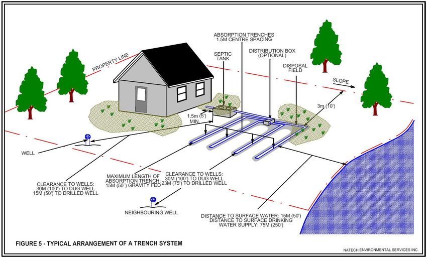
Version 6
                                                     Replaces: All Previous

Table of Contents
1     GENERAL ............................................................................................................... 4
    1.1 Abbreviations ................................................................................................... 4
    1.2 Conversion Factors ......................................................................................... 5
    1.3 Department of Public Safety (DPS), Technical Inspection Services Head
    Office .......................................................................................................................... 6
2     INTRODUCTION...................................................................................................... 6
    2.1 Engineered Systems ........................................................................................... 7
3     LOT EVALUATION .................................................................................................. 7
    3.1 Soil Conditions ................................................................................................. 7
    3.2 Slope and Interceptor Drains .......................................................................... 9
    3.3 Separation Distances ..................................................................................... 10
      3.3.1 Watercourses & Wetlands ...................................................................... 11
      3.3.2 Wells ......................................................................................................... 11
      3.3.3 Exemptions .............................................................................................. 12
    3.4 Lot Layout ....................................................................................................... 13
    3.5 Planning .......................................................................................................... 13
4     ON-SITE SEWAGE DISPOSAL SYSTEM DESIGN .............................................. 14
    4.1 Estimated Daily Sewage Flow ....................................................................... 14
    4.2 System Sizing ................................................................................................. 14
    4.3 Septic Tank ..................................................................................................... 14
    4.4 Conventional Design ..................................................................................... 17
      4.4.1 Pipe and Stone In-ground Trench .......................................................... 18
      4.4.2 Raised Mound Trench System ............................................................... 21
      4.4.2.1 Imported Sand ......................................................................................... 22
      4.4.2.2 Apron and Taper ...................................................................................... 23
      4.4.3 Leaching Chamber (Concrete) ............................................................... 24
      4.4.4 Infiltrative Chamber (Plastic) .................................................................. 26
      4.4.4.1 Approved For Use in New Brunswick .................................................... 27
      4.4.5 Holding Tank ............................................................................................ 28
      4.4.6 Pit Privy .................................................................................................... 29
      4.4.7 Pump......................................................................................................... 31
      4.4.8 Grease Trap or Chamber......................................................................... 34
      4.4.9 Oil / Water Separator ............................................................................... 35
    4.5 Repairs ............................................................................................................ 36
    4.6 Non-Conventional Design ............................................................................. 36
5     ADMINISTRATION ................................................................................................ 39
    5.1 Licensing ........................................................................................................ 39
    5.2 Licensing Requirements................................................................................ 39
      5.2.1 Issuance ................................................................................................... 40
      5.2.2 Revoking a licence .................................................................................. 40
    5.3 Course and Exam ........................................................................................... 41
    5.4 Application Process ....................................................................................... 43
    5.5. Revoking an Approval to Install .................................................................... 45
      5.5.1 Certificate of Compliance ....................................................................... 45
6     APPENDICES ........................................................................................................ 45

                                                          Page 2 of 62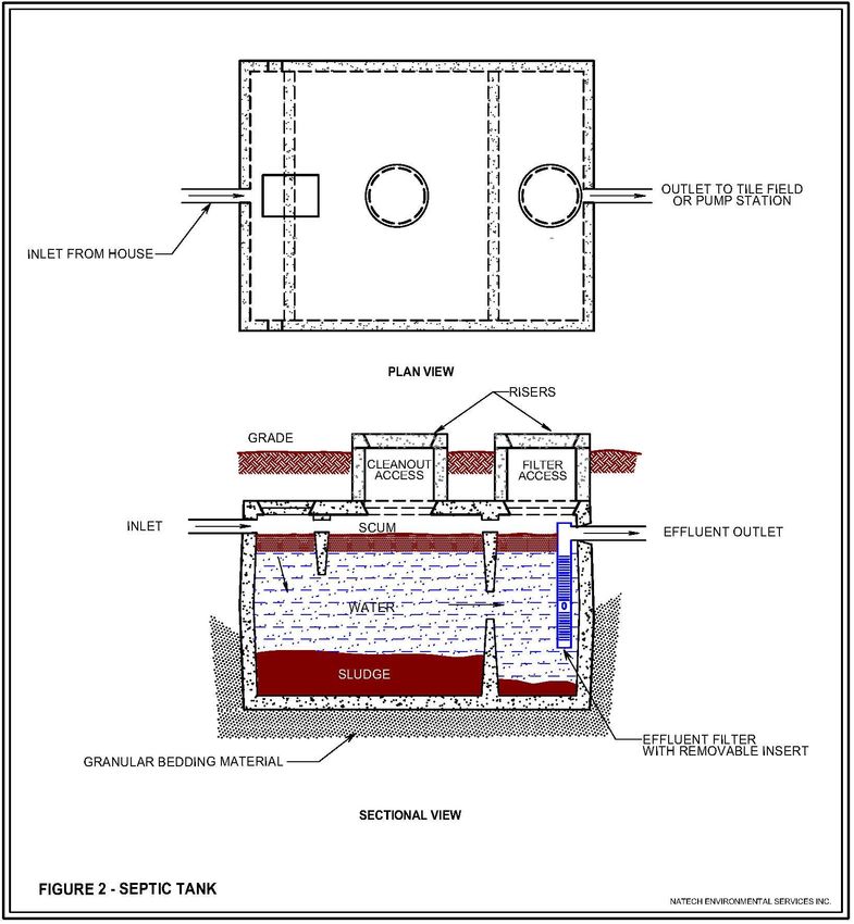
Version 6
                                              Replaces: All Previous

    APPENDIX A: Flow Diargram for Estimating Soil Texture by Feel & Structure
    Types …………………………………………………………………………………….46
    APPENDIX B ......................................................................................................... 48
    Minimum size building lot and septic tank, and minimum length of distribution pipe
    in an in-ground trench on-site sewage disposal system in relation to estimated daily
    sewage flow and permeability ................................................................................ 48
    APPENDIX B1 ....................................................................................................... 48
    Minimum size building lot and septic tank, and minimum number of 4'x8' concrete
    units in an in-ground trench on-site sewage disposal system in relation to
    estimated daily sewage flow and permeability ....................................................... 48
    APPENDIX C ......................................................................................................... 49
    Test Hole Requirements ........................................................................................ 49
    APPENDIX D ......................................................................................................... 50
    Estimated Daily Sewage Flows .............................................................................. 50
    APPENDIX D - Estimated Daily Sewage Flows ..................................................... 51
    APPENDIX E ......................................................................................................... 56
    Influent Wastewater Quality ................................................................................... 56
    APPENDIX F.......................................................................................................... 57
    Septic Tank Sludge and Scum Accumulation Rates for Other Than Residential ... 57
7   REFERENCES....................................................................................................... 62

                                                   Page 3 of 62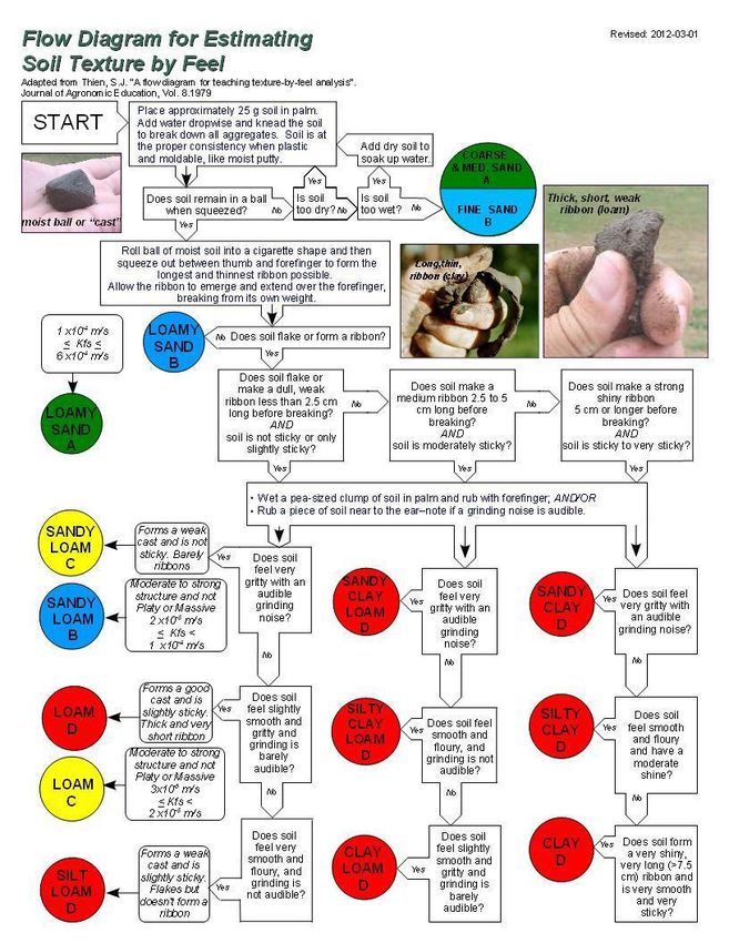
Version 6
                                     Replaces: All Previous

1 GENERAL
1.1    Abbreviations

cm              Centimetre
cm/sec          Centimetre per second (velocity or speed)
CSA             Canadian Standards Association
cu.             Cubic
CWA             Clean Water Act
ESF             Estimated Sewage Flow
EDSF            Estimated Daily Sewage Flow
ft              Foot
G               Gallon
g               Gram
ha              Hectare
hr              Hour
l               Hydraulic gradient
IG              Imperial gallon
IG per sq. ft   Imperial gallon per square foot
I gal           Imperial gallon per day (flow)
in              Inch
K               Soil permeability or hydraulic conductivity
kg              Kilogram
kPa             Kilopascals
l or L          Litres
L/p/yr          Litres per person per year
L/sq. m         Litres per square meter
lb              Pound
lpd             Litres per day (flow)
m               Metre
mi              Mile
min             Minute
mm              Millimetre
m/sec           Metre per second (velocity or speed)
m2              Square metre
m3/sec          Cubic metre per second (flow)
m3              Cubic metre
NSF             National Sanitation Foundation
PHA             Public Health Act
PID             Property Identification Number
psi             Pounds per square inch
Q               Sewage flow
sec             Second
sq.             Square
USG             US gallon
yd              Yard

                                        Page 4 of 62
Version 6
                                Replaces: All Previous

1.2   Conversion Factors

1 lb = 0.45359 kg                             1 kg = 2.2046 lbs
1 in = 2.540 cm                               1 cm = 0.3937 in
1 ft = 0.3048 m                               1 m = 3.281 ft
1 yd = 0.9144 m                               1 m = 1.094 yd
1 yd = 36.00 in                               1 m = 39.37 in
1 mi = 1.609 km                               1 km = 0.6214 mi
1 sq. in = 6.452 sq. cm                       1 sq. cm= 0.155 sq. in
1 sq. ft = 0.093 sq. m                        1 sq. m = 10.765 sq. ft
1 sq. yd = 0.836 sq. m                        1 sq. m = 1.196 sq. yd
1 acre = 0.405 ha                             1 ha = 2.471 acres
1 acre = 43560 sq. ft or 208.7 x 208.7 ft     1 hectare = 10,000 sq. m
1 sq. mi = 259 hectares                       1 sq. kilometre = 0.386 sq. mi
1 sq. mi = 2.59 sq. km                        1 cu. cm = 0.06102 cu. in
1 cu. in = 16.387 cu. cm                      1 cu. dm = 0.0353 cu. ft
1 cu. ft = 28,317 cu. cm                      1 L = 0.0353 cu. ft
1 cu. ft = 6.23 IG                            1 cu. meter = 1.308 cu. yd
1 cu. ft = 28.3 L                             1 cu. meter = 35.3 cu. ft
1 cu. yd = 0.765 cu. m                        1 cu. m = 220 IG
1 cu. yd = 168 IG                             1 cu. m = 1000 L
1 cu. yd = 765 L                              1 L = 0.220 IG
1 IG = 4.546 L                                1 L = 0.264 USG
1 IG = .0045 cu. m                            1 USG = .028 cu. ft
1 IG = 277.42 cu. in                          1 KPa = 0.145037 psi
1 IG water = 10 pounds                        1,000 mm pressure head = 9.807 kPa
1 USG = 3.785 L                               1 kPa = 102 mm pressure head
1 USG = .00378 cu. m                          1 kPa = 0.335 ft pressure head
1 IG = 49 L per sq. m                         1 L per sq. m = 0.020 IG per sq. ft
1 IG = 1.20 USG                               1 L per sq. m = 1 mm depth of effluent
1 USG = 0.83 IG                               1 IG per sq. ft = 1.92 in depth of effluent
1 ft pressure head = 304.8 mm pressure head
1 ft pressure head = 0.434 psi
1 psi = 2.301 ft pressure head
1 psi = 6.894757 kPa

                                   Page 5 of 62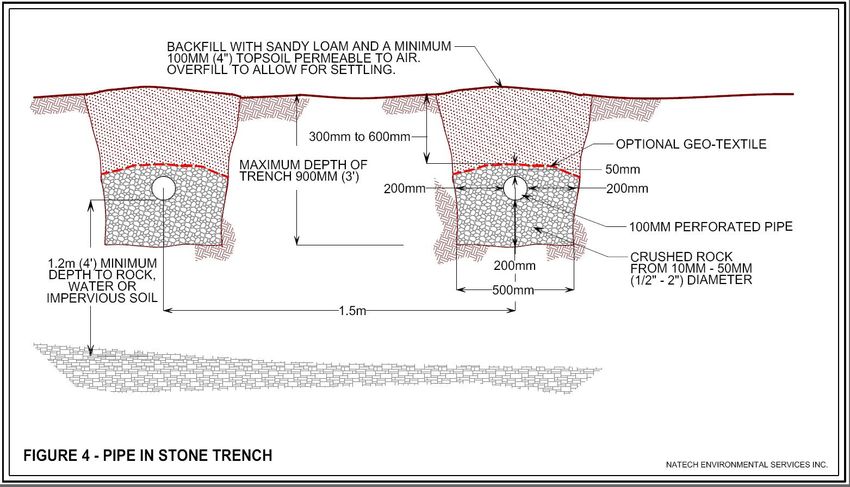
Version 6
                                   Replaces: All Previous

1.3   Department of Public Safety (DPS), Technical Inspection
      Services Head Office

Mailing Address:
Department of Public Safety
Technical Inspection Services
12 McGloin Street, 2nd Floor
Fredericton, NB E3A 5T8

DPS Toll Free Number: 1-844-249-6533
Fax Number: (506) 457-7394
Email : On-site.sewagedisposal@gnb.ca

2 INTRODUCTION
These Technical Guidelines have been established as part of, and in accordance with,
regulations respecting On-site Sewage Disposal Systems under the Public Health Act
(PHA). These Guidelines outline the siting and technical requirements to install, repair,
construct, or replace an on-site sewage disposal system in the Province of New
Brunswick.

Use of the information contained herein will be fundamental to ensuring compliant
installations and reducing the risk to public health and the environment. Licensees must
follow manufacturer’s Guidelines for all parts and materials in respect to the installation
of any on-site sewage disposal system.

An “on-site sewage disposal system”, as defined in the PHA, means a septic tank with
subsurface disposal field and all other on-site sewage disposal systems that are not
connected to a wastewater treatment facility approved by the Minister of Environment
and Local Government under the Clean Water Act (CWA). An on-site sewage disposal
system can be classified as either “conventional” or “non-conventional”.

It is mandatory that anyone installing, constructing, repairing, and/or replacing an on-
site sewage disposal system, or any of its parts, be licensed and have an approval. For
additional information on what is considered a repair, please refer to Section 4.5.

Approvals are issued for wastewater generated from personal hygiene, sanitation,
cooking, laundering, and other similar domestic purposes. This includes greywater but
does not include liquid and water-carried wastes generated by industrial or
manufacturing processes, sump pumps, gutters, drainage pipes, or runoff water.

                                      Page 6 of 62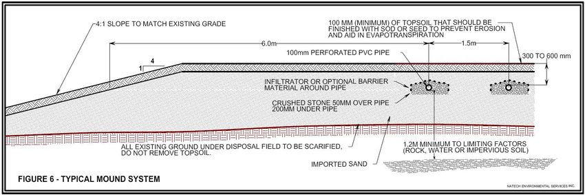
Version 6
                                      Replaces: All Previous

2.1 Engineered Systems

Engineered designs for onsite sewage disposal systems are permitted. Such systems
must be installed by a Licensee and designed by a Professional Engineer licensed
through the Association of Professional Engineers and Geoscientists of New Brunswick.

Engineered systems are mandatory if:
   • estimated daily sewage flows exceed 5,460 L/d
   • soil or other site conditions are not suitable
   • suitable imported sand is not available
   • non-conventional systems, including pressure dosed systems are proposed,
      unless the installer has a non-conventional license for such a system
   • the effluent exceeds the typical domestic wastewater strength, or
   • otherwise as directed by DPS

For more detailed licensing and approval requirements please refer to Regulation 2009-
137 under the PHA or Section 5 of this document. You may also contact the
Department of Public Safety, Technical Inspection Services Head Office listed under
Section 1.3.

3 LOT EVALUATION
On-site sewage disposal systems are designed for buildings with adequate separation
distances between neighbouring infrastructures, wells, impermeable soils, bedrock,
watercourses, right-of-ways, easements, property boundaries and other limiting factors
which may apply. When evaluating lots, consideration must be given to soil conditions,
slopes, interceptor drains, rock outcropping, separation distances, lot layout and
planning.

3.1    Soil Conditions

Soil type is one of the most important deciding factors in whether a lot will be suitable
for an on-site sewage disposal system and what the design will be. The purpose of the
soil is to provide for infiltration, dispersal, and final treatment of effluent before it reaches
bedrock, groundwater or horizontal setbacks.

To appropriately assess the suitability of in-situ soils, it is necessary to conduct a visual
examination of a test pit. Test holes shall be dug for all applications and be located
within approximately 3m (10 feet) of where the proposed disposal field of the on-site
sewage disposal system is to be located.

Digging a test hole directly in the existing field area could contaminate groundwater and
is not recommended. The test hole shall be at least 1.8 m (6 feet) deep unless bedrock
is encountered. Please refer to Appendix C for additional details on test hole
requirements. The soil texture, density, structure, depth and colour in the test pit will

                                         Page 7 of 62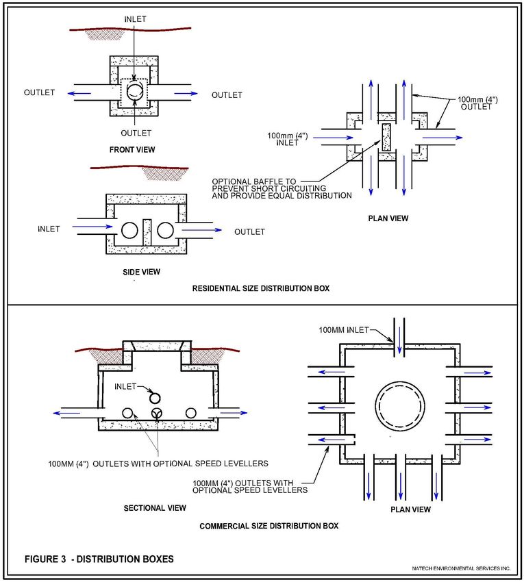
Version 6
                                    Replaces: All Previous

permit the Licensee to predict the permeability (i.e. the rate of water drainage) and
classify the soil. The test hole will also show the presence or absence of groundwater,
bedrock (the solid rock that underlies loose material such as gravel, sand, loam or clay,
and includes material such as limestone, sandstone, shale, etc. ) and/or impermeable
soils (such as clay). All of this will determine whether an in-ground trench or raised
mound trench sewage disposal field will be required as well as how much sand must be
imported (if applicable). It is important to remember that an in-ground trench is
permitted to be installed in “A”, “B” or “C” soil.

The applicable soil texture of each horizontal soil profile (soil layer) in the test pit shall
be evaluated and described in the field by using the “Flow Diagram for Estimating Soil
Texture by Feel” which can be found in Appendix A. Installers must determine the
applicable soil texture, but should also consider the soil structure, density and
permeability. As the texture of the soil becomes more silty the permeability (the rate of
water drainage) of the soil decreases.

Please refer to Table 6 for a description of the various soil textures from sand to loam to
clay and how these textures can be used to classify an in-situ soil as “A”, “B”, “C” or “D”.
Categories “A”, “B” and “C” correspond to Appendix B.

Category “D” corresponds to soil that is too permeable (drains too fast) or soil that is
impermeable (soil that does not drain well – such as clay) and therefore cannot be used
to select a system. In these situations, a raised mound sewage disposal field or
engineered design is required.

Technical Notes:

1) Soils that have a platy or massive structure, or are very compact to dense, may not
   meet the recommended permeability (i.e. field saturated hydraulic conductivity -
   which is abbreviated as KFS) range predicted by soil texture alone. An in-situ
   permeability test can be conducted using a constant head permeameter, to verify
   that the permeability (KFS) is within an acceptable range for the soil category. Please
   refer to the diagrams in Appendix A or call the Department of Public Safety,
   Technical Inspection Services Head Office for more information.

2) The hydraulic conductivity of the soils listed in Appendix B & B1 are as follows:

              Type “A” is 1x10⁻⁴ m/sec ≤ Kfs ≤ 6x10⁻⁴ m/sec.
              Type “B” is 2x10⁻⁵ m/sec ≤ Kfs < 1x10⁻⁴ m/s
              Type “C” is 3x10⁻⁶ m/sec ≤ Kfs < 2x10⁻⁵ m/s

                                        Page 8 of 62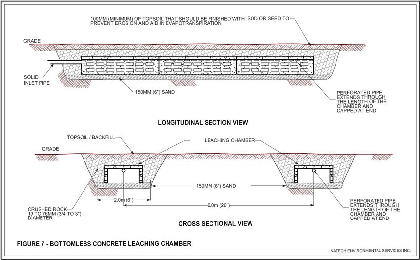
Version 6
                                  Replaces: All Previous

3.2   Slope and Interceptor Drains

Slope will have an effect on the rate at which water from the distribution piping moves
through the soil down slope of the field. As such slopes may limit the installation of
various types of systems. An interceptor drain or diversion ditch may be required in
certain situations to divert or intercept surface water and groundwater upslope of a
disposal field. This will prevent surface and groundwater moving down the slope from
saturating the soil of the disposal field during wet seasons. Please refer to Figure 1.

                                     Page 9 of 62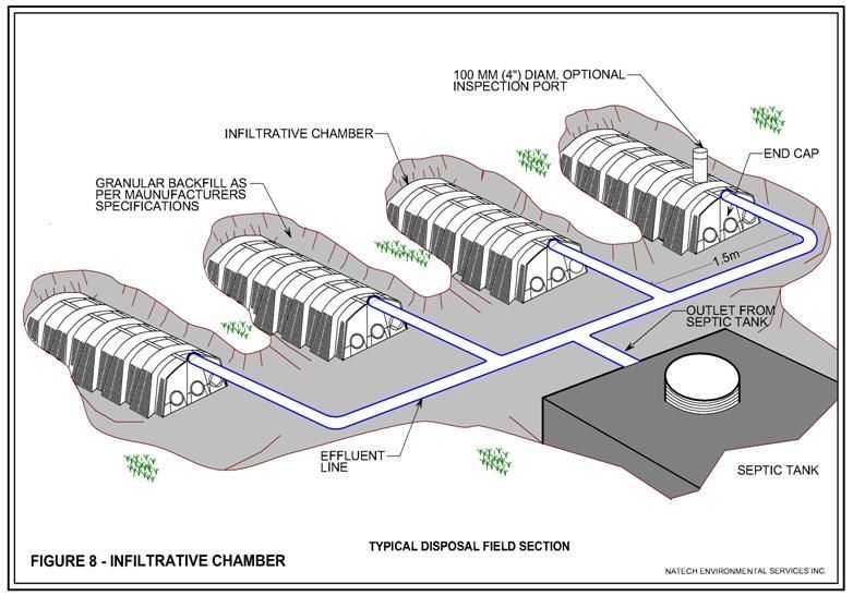
Version 6
                                        Replaces: All Previous

3.3    Separation Distances

Table 1 outlines required separation distances. Distances from the disposal field shall
be measured from the nearest distribution line.

                 Table 1: Horizontal and Vertical Separation Distances

                                                      Septic Tank or Pump
                     Feature                                                 Disposal Field
                                                            Chamber
                                                        (m)        (ft)     (m)        (ft)
  Drilled Well                                            15      50         23        75

  Dug Well and/or Sandpoint Well                          30      100        30       100

  Bodies of water normal high water mark (not            15*      50*       15*        50*
  used as a designated potable water supply)

  Bodies of water normal high water mark (used            90      300        75       250
  as a designated potable water supply)

  Building Foundation, Foundation Drain and any           1.5      5         3.0       10
  part of

  Property Line or Intermittent ditch                     3.0     10        3.0        10

  Limiting factors (such as impermeable soil,
                                                         N/A      N/A       1.2**      4**
  groundwater table, bedrock)
  *     Activity within 30m (100 ft) of a watercourse requires a Watercourse Alteration Permit
        from NB Department of the Environment and Local Government
  **    From the invert (bottom) of the pipe and/or pipe opening of unit

The “normal high water mark” is defined under the Crown Lands and Forests Act as the
visible high water mark of a lake or river where the presence and action of water are so
usual and so long continued in ordinary years as to mark upon the bed of the lake or
river a character distinct from that of the bank thereof with respect to vegetation and the
nature of the soil itself.

                                          Page 10 of 62
Version 6
Replaces: All Previous
3.3.1 Watercourses & Wetlands
The separation distances from on-site sewage disposal systems to watercourses
described in Section 3.3 differ from those in the CWA respecting setbacks for work within
30m (100 ft) of a wetland or watercourse. If any work is to be undertaken within this 30m
(100 ft) setback it is the property owner’s responsibility to ensure that the Department of
Environment and Local Government is contacted and that all necessary permits are
obtained before commencing the work.
A “watercourse" is defined in the CWA as the full width and length, including the bed,
banks, sides and shoreline, or any part, of a river, creek, stream, spring, brook, lake,
pond, reservoir, canal, ditch or other natural or artificial channel open to the atmosphere,
the primary function of which is the conveyance or containment of water whether the flow
be continuous or not.
A “wetland” is defined in the CWA as Land that (a) either periodically or permanently,
has a water table at, near or above the land’s surface or that is saturated with water, and
(b) sustains aquatic processes as indicated by the presence of hydric soils, hydrophytic
vegetation and biological activities adapted to wet conditions.
Wetlands include marshes, bogs, wet meadows, peatland and swamps. It is the
client’s responsibility to confirm if the property is subject to wetland regulations.
3.3.2 Wells
A “well” is defined in the CWA as an artificial opening in the ground from which water is
obtained or an opening made for the purpose of exploring for or obtaining water. A “dug
well” is defined in the Water Well Regulation 90-79 under the CWA as a well
constructed by digging, either manually or mechanically. A sandpoint well is currently
not defined under this legislation; however, it is considered a dug well for the purposes
of maintaining setbacks. As with dug wells, sandpoint wells are shallow and therefore
susceptible to surface water contamination.
Where an abandoned well exists on a property that is within setbacks to the on-site
sewage disposal system an Approval will not be issued until the well has been properly
decommissioned or after being provided sufficient proof that a well has been or is to be
decommissioned (i.e., receipt or letter of intent from property owner). In such cases, the
Licensee shall be referred to DENV for advisement on proper decommissioning. Proof
of decommissioning must be submitted along with the Notice of Installation.
Page 11 of 62Version 6
Replaces: All Previous
3.3.3 Exemptions
For lots with existing services, an approval may be granted where separation distances
or lot size requirements specified in these Guidelines cannot be met, only if the design
and location being proposed is reducing the risk of a health hazard. A risk assessment
will be conducted by the Department to determine appropriate exemptions.
Vacant Lots
For vacant lots, minimum separation distances must be met for conventional system
installations. Appendix B & B1 apply when determining lot size and configuration
requirements.
For vacant lots smaller than 4000 m2 (1 acre) approved by the Planning Commission
prior to 1976, the Department may grant an exemption to approve on-site sewage
disposal system up to a maximum of 1365 L/day EDSF as long as all required
separation distances are met.
Non-conventional technology
Where an approval is being granted for a non-conventional technology, separation
distances and lot sizes may be reduced where documentation is provided to indicate the
effluent going into the soil has been pre-treated to improve its quality (Ex: BOD, TSS,
etc.) with secondary treatment after the septic tank.
Documentation must be stamped by a professional engineer licensed to practice
engineering in NB.
For non-conventional technologies without pre-treatment (such as contour and sloping
sand filters) separation distances must be respected.
Page 12 of 62Version 6
Replaces: All Previous
3.4 Lot Layout
When planning the layout of a lot, it is important to consider everything which will
eventually be on the lot to help avoid unnecessary cost or future limitations. Wherever
possible, the well should be located up slope of the on-site sewage disposal system
with the required separation distances outlined in Section 3.3.
The following should be considered when assessing a lot:
▪ Property size and dimensions, including location of easements, right of ways,
and driveways;
▪ Percentage and direction of slope;
▪ Dimensions and layout of the on-site sewage disposal system;
▪ Original and expected finished ground elevations where the system is proposed
to be located, or is currently located in the case of a repair, replacement, etc.;
▪ Separation distances between both the septic tank and disposal field and house
and other buildings, property lines, property wells, adjacent wells, and bodies of
water within 100m (330 ft) of any part of the proposed system;
▪ Estimated daily sewage flow to be treated by the system;
▪ Soil characteristics as determined by a test pit inspection and, where required,
hydraulic conductivity test, soil sieve analysis, and/or another soil evaluation
method acceptable to the Minister;
▪ Identification of any limiting factors such as bedrock, groundwater table, and/or
impermeable soil;
▪ Interceptor drains or diversion ditches and foundation draining system; and
▪ Any future development on the lot, such as swimming pool, garage, etc.
3.5 Planning
Housing developments or subdivisions where many houses are located on minimum
sized lots with on-site sewage disposal systems and wells can be problematic for a
number of reasons, namely the required separation distances for location of wells and
on-site sewage systems. Potential buyers of such lots in subdivisions should consult a
licensed septic system installer to ensure that the lot they intend to purchase and
develop is suitable for an on-site sewage disposal system (i.e., separation distances,
flood plains, future development, etc.). Other regulations may also apply; therefore, one
must be certain to consult with the local Municipal or Planning Authority to ensure all
laws, regulations and by-laws can be met.
If you are purchasing an existing dwelling or building with an on-site sewage disposal
system, you should obtain details on its design, condition and location prior to purchase.
Page 13 of 62Version 6
Replaces: All Previous
4 ON-SITE SEWAGE DISPOSAL SYSTEM DESIGN
4.1 Estimated Daily Sewage Flow
Estimated daily sewage flows for on-site sewage systems shall be calculated based on
design flow criteria attached as Appendix D. Lot dimensions and area (see Appendix
B) must be considered once the total daily sewage flow is calculated.
4.2 System Sizing
A conventional on-site sewage disposal system typically consists of a septic tank and a
disposal field. On-site sewage systems are designed and sized based on the estimated
daily sewage flow that the system will be receiving while also considering the soil
conditions and permeability rates (i.e. how quickly the water drains), as estimated by a
test pit assessment (or other method).
Coarse and medium sands have the greatest capacity to drain water and clay has the
least. Soil must receive the septic tank effluent at a rate which will allow for additional
treatment and reduce the potential for groundwater contamination while at the same
time prevent breakout and flooding or ponding within the disposal field. The disposal
field shall be sized based on the soil with the slowest permeability within 1.2m (4 feet)
below the distribution pipe.
Soil types which conduct water too slowly or too rapidly will require a mound or built-up
disposal field. Please refer to Appendix B for disposal field sizes in relation to soil
permeability and estimated daily sewage flow. The disposal field size increases as the
flow increases and soil permeability decreases. If the situation warrants, the Licensee
may employ soil evaluation methods such as a hydraulic conductivity test of the soil in
the proposed area.
4.3 Septic Tank
All septic tanks shall be installed level. Therefore, it is necessary to ensure the pad is
level prior to lowering and installing the tank.
Prefabricated septic tanks must conform to the most recent version of CSA Standard
B66 and shall:
▪ Have a visible stamp. If the stamp is unclear or not visible on the tank, the
Licensee may be required to provide proof that the tank conforms to the CSA
Standard.
▪ Have a minimum liquid capacity of 3410L.
▪ Be designed to carry a minimum of 600 mm of earth cover. The earth cover
shall not exceed the maximum burial depth for which the tank is designed.
▪ Be constructed with two compartments, where the liquid capacity of the first
compartment is equal to two-thirds of the total septic tank capacity. Note the
Page 14 of 62Version 6
Replaces: All Previous
capacity of a siphon or pump compartment is not included as part of the septic
tank capacity.
▪ Be constructed with baffles at the inlet and outlet ends to prevent “short-
circuiting” or direct flow through of effluent. For an example, please refer to
Figure 2.
▪ Be constructed of concrete, fibreglass or polyethylene. (Steel tanks are not
permitted as they are subject to corrosion rates significantly higher than the
others and may have a shorter life depending upon ground conditions).
▪ Be water-tight.
▪ Be located, including depth below grade, so that they are accessible for septage
removal, service, and maintenance. Access shall be provided to each
compartment with openings at or above grade.
▪ Be equipped with an effluent filter meeting NSF Standard 46 that is easily
accessible for maintenance, as per the manufacturer’s Guidelines. Unless
otherwise stated by manufacturer’s guidelines, it is recommended that effluent
filters have a permanently attached handle that extends to within 150 mm of the
access riser rim. The handle should be of such a material that allows easy
removal and replacement.
▪ Ensure that all access openings have a secure lid or cover.
▪ Ensure that all piping connections shall be watertight and not allow groundwater
and surface water infiltration or wastewater leakage.
▪ Ensure that all pipe joints from building to the septic tank and from the septic
tank to, and including, the header are water tight. (e.g. solvent cement joint,
mechanical joint or as approved by the pipe manufacturer)
Decks or other structures that can limit access should not be built over septic tanks or
pump chambers. The location and depth below grade of a septic tank should not
exceed the suction elevation of vacuum trucks. Septic tanks should be protected from
overhead loads or stresses greater than the tank-load-bearing capabilities.
Each type of tank has specific installation requirements to ensure proper operation and
longevity. Septic tanks may need to be secured against hydraulic uplift in areas where
there is potential for high groundwater levels. The minimum slope in the pipe from the
house to the septic tank is 3mm per 300mm of length or 1%. Also, for more details,
please refer to the most recent version of the National Plumbing Code of Canada that is
being used by the Department of Public Safety.
The CSA standard specifies inlet and outlet connections, air space, and access
openings among others. The minimum liquid depth in a tank is 0.9m (3ft).
Compaction of bedding material under inlet and outlet piping is essential to support
piping. Please refer to the most recent version of the National Plumbing Code that is
being used by the Department of Public Safety.
Refer to Figure 2 for an illustration of the interior of a septic tank.
Page 15 of 62Version 6
Replaces: All Previous
The manufacturer’s instructions for placing and backfilling septic tanks, which may
include the use of pea gravel, must be followed. Empty septic tanks have been known
to lift out of the ground under high water table conditions. Therefore, septic tanks under
high water table conditions must be secured to prevent uplift.
Two-piece septic tanks that arrive on-site with joining damaged edges, or those that
have been installed with improper caulking, will be rejected and shall be removed from
the installation.
Information on septic tank sludge and scum accumulation rates can be found in
Appendix F.
Page 16 of 62Version 6
Replaces: All Previous
4.4 Conventional Design
A conventional sewage disposal system, as defined in Regulation 2009-137, is an on-
site sewage disposal system with a septic tank and subsurface disposal field system
with sewage flows not exceeding 5460 lpd and includes a sewage holding tank and pit
privy but not a contour system. This does not include a pressure-dosed infiltrative
plastic chamber system.
Approvals for conventional on-site sewage disposal systems are issued only for
wastewater* generated from personal hygiene, sanitation, cooking, laundering, and
other similar domestic purposes. This includes greywater but does not include liquid
and water-carried wastes generated by industrial or manufacturing processes, sump
pumps, gutters, drainage pipes, or runoff water.
*For expected influent raw wastewater strengths please refer to Appendix E.
Other types of wastes, such as metals or persistent organic chemicals, should be
collected and treated separately. Facilities such as car washes or hospitals where
chemicals may upset the tank and disposal field treatment processes need to be
considered prior to design and may require an engineered system. Pre-treatment for
grease or sand may be necessary depending on the facility.
Distribution of sewage in a disposal field must be equal. Distribution lines shall be laid
parallel to the contour (across the natural slope of the land) and perpendicular to the
groundwater flow in the area where the on-site sewage disposal system is proposed.
The use of geotextile is recommended to be placed over the crushed rock (10mm-
50mm) before backfilling. Geotextile helps prevent the infiltration of fine soil into the
trench gravel.
A distribution box (see Figure 3) may be used instead of a level header between the
septic tank and gravity-fed disposal field to ensure all distribution lines are loaded
equally. Distribution boxes may be concrete or plastic and consist of one inlet with a
varying number of outlet holes.
A distribution box must be installed level. A distribution box must be designed to provide
a manageable flow and to prevent short-circuiting and have a baffle in front of the inlet.
It is recommended that distribution boxes are insulated for frost protection, as well as be
installed on a gravel base. Adjustable flow equalizers may be used to ensure equal
distribution even if a distribution box does not remain level.
Page 17 of 62Version 6
Replaces: All Previous
4.4.1 Pipe and Stone In-ground Trench
Where in-situ soil conditions permit (see Section 3 – Lot Evaluation), the field design
may be an in-ground trench. The type of design is constructed with trenches dug into
original ground. It is important to remember that an in-ground trench is permitted to be
installed in “A”, “B” or “C” soil.
Page 18 of 62Version 6
Replaces: All Previous
A trench field consists of several individual trenches of one or more level headers with
equal distribution, or of a distribution box, dug into existing soil with clean crushed rock
on which the perforated pipe is laid and graded. The perforated pipe is also covered
with clean crushed rock.
The perforated distribution pipe must meet CAN/CSA Standards B181.1, B181.2,
B182.1 and B182.2. The ends of the distribution lines are capped in a trench field.
Table 2 and Figures 4 & 5 outline trench construction details.
Table 2: Trench Construction Details for Pipe and Stone Systems
Size Requirement
Trench information
Metric Units Imperial Units
Minimum Trench Width 450mm 18”
Maximum Trench Depth 900mm 36”
Maximum Trench Length 15m 50’
Trench Separation (centres) 1.5m 5’
Minimum Total Field Length 60m 200’
Depth of clean crushed stone
(under/over pipe) 200mm / 50mm 8” / 2”
Size of crushed stone 10mm – 50mm ½” – 2”
Slope of Perforated Pipe 50mm per 15m 2” per 50’
Top Header in Field non-perforated and level non-perforated and level
The disposal field requires a minimum 30cm (12 in) of soil cover that allows air to
permeate. The cover layer should be able to support vegetation and must consist of at
least 10cm (4 in) of topsoil and should be finished with sod or seed to prevent
erosion and aid in evapotranspiration. The cover should not exceed 60cm (24 in) in
thickness unless alternative means of aeration are provided.
Page 19 of 62Version 6 Replaces: All Previous Page 20 of 62
Version 6
                                    Replaces: All Previous

4.4.2 Raised Mound Trench System

When a test pit evaluation identifies that limiting factors are present, it is necessary to
increase the distance from the invert of the distribution pipe to the limiting factor by
adding imported sand. Limiting factors include bedrock, groundwater or seasonal high
water table, impermeable soil (like clay) or soil that is too permeable (i.e. drains too fast
such as very coarse and gravelly sands). Disposal fields which are raised in this
manner are called mounds. The depth of imported sand required is determined by the
in-situ soil conditions in the area as determined by a test pit inspection. If a portion of
the in-situ soil is to be used to construct the mound, the system shall be sized based on
the soil classification (“A”, “B” or “C”).

The area under the proposed mound must be scarified parallel to the slope.
"Scarification" means loosening and breaking up the soil in a manner that prevents
smearing of the soil surface while at the same time maintaining soil structure. This is
necessary to help allow the passage of effluent into the native soil. A cultivator, mould
board plough, or chisel plough should be used to scarify the native soil. No equipment
shall be driven over the scarified area.

Stumps shall be removed, and sod and root layers shall be stripped before the imported
sand is placed.

Imported sand should be placed so that it is level with the top of the proposed trench.
The trench should then be excavated into the sand with the trench bottom level in both
width and length. This must be done to ensure that there is sufficient sand under the
field to meet separation distances and limiting factors.

Imported sand shall be placed in lifts not exceeding 300 mm, as this will help ensure
that the sand does not settle after placement.

Distribution lines shall be laid parallel to the contour (across the natural slope of the
land) and perpendicular to the groundwater flow in the area where the on-site sewage
disposal system is proposed.

The ends of the distribution lines in gravity fed disposal beds are to be connected with
either solid or perforated distribution pipe so as to be level. (Note: for sloped mounds
the ends must be capped unless the distribution pipes are located on the same level in
which case they shall be connected). If perforated distribution pipe is used for this
purpose, it shall be surrounded by clean crushed rock and shall not be considered in the
total linear system length.

                                       Page 21 of 62
Version 6
Replaces: All Previous
4.4.2.1 Imported Sand
Imported sand that meets the specifications in Table 3 is required to be used in a
mound or above-ground system. The selection of suitable sand is critical to the proper
design and function of a mound system. Sandstone does not typically meet the
requirements to be considered a suitable sand. Material containing too many fines
(e.g.: clay and silt) cannot accept septic tank effluent at an acceptable rate without
severe clogging. Material which is too coarse (e.g. predominantly very coarse sand or
gravels) will allow septic tank effluent to pass through too quickly and may not achieve
an acceptable level of treatment. Note: For plastic infiltrative chambers sand meeting
manufacturers specifications must be used.
It is important to remember that material in a pit may vary and this can be particularly
true for pit-run sand that is dug out of the bank. Manufactured sands that have been
produced by crushing and/or screening tend to have the most consistent results.
However, different stockpiles of material produced at different times can still vary in
gradation, resulting in varying permeability.
It is time-consuming and expensive to remove and replace material that does not meet
the specification. It is much better to be confident that the sand brought to the site is
suitable.
Table 3 Material specifications for Imported Sand
Grain Size Distribution Specifications
9.5 mm (⅜ in) 80 to 100% passing
4.75 mm (No. 4) 80 to 100% passing
75 μm (No. 200) *≤8% passing in the sand (4.75 mm minus) fraction
D10 in the sand (4.75 mm minus) fraction 0.15 to 0.50 mm
Cu = D60/D10 (unit-less) in the sand (4.75 mm
1 to 6.0
minus) fraction
Permeability
KFS 5 × 10⁻⁵ to ≤ 6 × 10⁻⁴ m/s
*A lower percentage passing is better. Less than 5% is recommended.
Compliance with Table 3 can be determined by conducting either a sieve analysis to
verify the grain size distribution, D10 and CU, or a permeability test to determine KFS.
To determine the grain size distribution a sieve analysis must be completed. This is
typically completed at a soils-testing laboratory. The analysis is conducted by passing a
representative sample of sand through a set of sieves of known mesh sizes. The sieves
Page 22 of 62Version 6
Replaces: All Previous
are mechanically vibrated, and the weight of material retained on each sieve is
measured and converted into a percentage passing by weight. A report is prepared to
document the percent passing for each sieve size.
The D10 and CU value listed in Table 3 are scientific values that are calculated from the
results of the sieve analysis. They provide a quick indication of the expected
permeability (the rate effluent will flow through) of the sand.
D10 (effective size)
The particle size for which, by weight, 10% of the sample is finer than. The smaller the
D10 number, the more silt, fine and very fine sand particles are contained in the imported
material. This can be an indicator of a low permeability.
Cu (uniformity coefficient)
Indicates the range of particle sizes contained in the sand fraction of an imported
material. The higher the Cu number, the greater the range of particle sizes. Therefore,
high Cu number generally means the sand will have a lower permeability because the
small particles fill the void between the medium particles, and the medium particles fill
the voids between the larger particles.
KFS (Field saturated hydraulic conductivity)
Permeability (rate effluent will flow through sand) is expressed scientifically as hydraulic
conductivity (abbreviated KFS).
The KFS of imported sands can be determined through:
a) field permeability conducted in a representative bed or test pad of imported sand
materials (i.e., of appropriate vertical thickness and density) by use of a Constant
Head Permeameter;
b) Simplified Falling Head Permeability test on representative samples of imported
sand materials;
c) *laboratory hydraulic conductivity testing (KS);
*Note: Laboratory hydraulic conductivity testing determines KS. KFS is typically KS/2.
4.4.2.2 Apron and Taper
In mound disposal fields, proper design of the surrounding apron and taper is crucial to
minimize breakout at the sides. The apron is to consist of 6m (20 feet) on all down slope
ends of the disposal field and 3m (10 feet) on all other sides. The taper is to be at a 4:1
(horizontal:vertical) ratio of slope from the edge of the apron material to original ground
elevation.
To construct the apron:
At the top of the soil absorption area (i.e. the bottom of the pipes, plastic chamber or
concrete leaching galley inlet) extend the sand “buffer” horizontally from the end of the
Page 23 of 62Version 6
Replaces: All Previous
trench out as far as is necessary (3m or 6m if downslope). The 4:1 taper then begins at
the end of this apron (sand “buffer”) and should slope to match finish grade. The
mound must then be completed by extending the 4:1 taper upwards from the end of the
apron to the finished elevation.
Finished elevation means the required 0.3m (1ft) to 0.6m (2ft) of backfill (with sandy
loam or topsoil) above the top of the pipe. The top 100mm (minimum) should consist of
topsoil that is finished with sod or seed to prevent erosion and aid in evapotranspiration.
This is in addition to and after placement of the required 50mm (2in) of gravel over the
pipe.
Absorption area means that area in a subsurface disposal field in which wastewater is
distributed for infiltration to the soil. This begins at the pipe invert or equivalent.
Figure 6 provides for an overview of a typical mound system.
4.4.3 Leaching Chamber (Concrete)
Leaching chambers are concrete units that can be used in place of perforated pipe and
stone in distribution lines. A clogging mat will develop in these units resulting in a long-
term permeability similar to other systems. Leaching chambers must have a perforated
pipe that extends through the length of the units and be capped at the end. Leaching
chambers must be installed level. This is done by placing a sufficient quantity of sand
(see specification in Table 3) under each unit. The units must have a minimum of 30cm
(12 in) coarse gravel around the outside. Coarse gravel is classified as 19mm to 76mm
(3/4in to 3in) consistent with the Unified Soil Classification System.
Page 24 of 62Version 6
Replaces: All Previous
Where more than one row of leaching chambers is required they must be placed at a
minimum of 6m (20 ft) centre to centre.
A leaching chamber field must be covered with a minimum of 30cm (12 in) of soil cover
that allows air to permeate. The cover layer should be able to support vegetation and
must consist of at least 10cm (4 in) of topsoil and should be finished with sod or seed to
prevent erosion and aid in evapotranspiration. The cover should not exceed 60cm (24
in) in thickness unless alternative means of aeration are provided.
The size approved for use in New Brunswick is 1.2m x 2.4m x 0.6m deep. See
Appendix B1.
Due to the weight of concrete leaching chambers, it is very important that the sand
underneath be compacted to prevent settling of these units.
For concrete leaching chambers, the distance to limiting factors shall be measured from
the bottom of unit and not the invert of the pipe. The bottom of the unit shall be at least
1m (3.3 ft) from the limiting factors. Figure 7 provides graphic representation of a
bottomless concrete leaching chamber. Please note that various designs can be
considered such as “interlocking”. The bottom of the unit must be measured to the
limiting factor.
Table 4: Trench Construction Details for Leaching Chambers
Size Requirement
Trench information
Metric Units Imperial Units
Minimum Trench Width 2m 6’
Maximum Trench Depth 900mm 36”
Maximum Trench Length 15m 50’
Trench Separation (centres) 6m 20’
Minimum Total Field Length 6 units 6 units
Crushed Rock (sides of galleys)
300 mm 12”
Size of Crushed Stone 19mm – 76mm ¾” – 3’
Slope of Galleys level level
Top Header in Field non-perforated and level non-perforated and level
Depth to Limiting Factor from the
1m 3’
bottom of the infiltrator
Page 25 of 62Version 6
Replaces: All Previous
4.4.4 Infiltrative Chamber (Plastic)
Infiltrative (plastic) chambers shall be installed in keeping with the technical intent of
trench and mound fields. Systems shall be designed to distribute the effluent evenly.
Distribution lines shall be laid parallel to the contour (perpendicular to the natural slope
of the land) in the area where the on-site sewage disposal system is proposed and no
one line shall exceed 15m (50ft).
Sand must meet manufacturer’s specifications. If uncertain, it is recommended to have
a soil analysis completed.
Please refer to Figure 8 for a diagram of an infiltrative chamber.
Page 26 of 62Version 6
Replaces: All Previous
As previously stated, the vertical separation distance between the invert (bottom) of a
distribution pipe in a sub-surface disposal field and limiting factors shall be at least 1.2m
(4 ft). Similarly to concrete leaching chambers, the distance from the bottom of the
trench to the limiting factor shall not be less than 1.0m (3.3 ft). For infiltrative (plastic)
chambers, the distance to a limiting factor of 1.0m (3.3 ft) must be measured from the
bottom of the trench (or unit) in which the infiltrative chamber is installed.
It is the responsibility of the Licensee to ensure that infiltrative chambers are
installed as per Manufacturer’s Handling and Installation Guides. Please contact
the manufacturer or their distributors directly for more information.
4.4.4.1 Approved For Use in New Brunswick
Following is a list of infiltrative chambers currently approved and available for use in
New Brunswick. The corresponding length of each unit is indicated in brackets.
Note that this list is subject to change.
Infiltrator Water Technologies, LLC:
Quick4 Standard (4ft) H-10 Standard (6.25ft)
Quick4 High Capacity (4ft) H-10 High Capacity (6.25ft)
Page 27 of 62Version 6
Replaces: All Previous
Standard BioDiffuser (6.25ft) ARC 36 High Capacity (5ft)
ARC 36 Standard (5ft)
Each of the infiltrative chambers listed above will receive a 50% reduction in total length
of that required for a perforated pipe and stone distribution system.
4.4.5 Holding Tank
Applications for holding tanks must be submitted in accordance with Section 5.4 of
these Guidelines. Separation distances shall be the same as those for septic tanks
outlined in Table 1.
Holding Tanks, or total retention tanks, are considered only in the following
circumstances:
▪ When a conventional or non-conventional on-site sewage disposal system
cannot be installed on an existing building lot and all separation distances listed
in Table 1 can be met. A lot is considered an existing building lot if it currently
has an existing building (including cottages, travel trailers, etc.) with wastewater
services or proof of having such services is provided.
▪ For temporary use such as special events or construction/work camps not
exceeding 12 months. Seasonal use of cottages, travel trailers, other dwellings,
etc. are not considered “temporary use”.
▪ As an interim measure on a building lot that will be serviced by a communal
sewerage system within 1 year with written confirmation from the municipality.
▪ For non-residential use (i.e., guard house) with an estimated daily sewage flow
not exceeding 90 lpd.
The Chief Plumbing Inspector reserves the right to use his or her discretion and,
depending on local conditions or circumstances, approve only an above-ground holding
tank.
Holding tanks shall:
▪ Conform to the most recent version of CSA Standard B-66 or have certification of
equivalency acceptable to the Minister.
▪ Be sized for the estimated daily volume of sewage with a minimum size of 9000L
(2000 IG).
▪ Be pumped by a licensed septage hauler at a frequency dictated by usage.
▪ Be located, including depth below grade, so that they are accessible for septage
removal, service, and maintenance. Decks or other structures that can limit
access should not be built over holding tanks.
▪ Have access openings and extensions, risers, and piping connections that are
watertight and do not allow groundwater and surface water infiltration or
wastewater leakage.
Page 28 of 62Version 6
Replaces: All Previous
▪ Be water-tight without joints or seams with the exception of welded or
manufactured watertight seams and shall have no holes other than the inlet and
access for pumping. A leak test on a 2-piece tank assembled on-site may be
required by the Inspector where site conditions are high risk, such as when a
tank is installed on fissured bedrock and any leakage could contaminate
groundwater. Leak testing involves filling the tank with water to a level above the
tank inlet pipe at least 24 hours prior to requesting a final inspection of the
system.
▪ Be connected to the plumbing via a water-tight connection.
▪ Be equipped with a signalling device consisting of a switch and alarm which will
provide a visible or audible signal when the tank is 80% full. Other forms of
warning devices which achieve the same result and are reliable may be
accepted. The licensee must contact the Department of Public Safety (DPS)
for inspection of electrical components.
o If used with a pump, the tank must have a warning device inter-wired with the
pump so as to prevent pump operation when the tank is 90% full.
▪ Be anchored with strapping to a concrete slab of sufficient weight where there is
concern with hydraulic pressure.
It is the responsibility of the Licensee to ensure holding tanks are installed as per
Manufacturer’s Handling and Installation Guides.
Where manufacturer’s instructions are not given, normal construction practices shall be
followed to provide a stable foundation for the tank. The bottom of the tank shall be
supported evenly over its length or, if appropriate, at specific loading points. The
Licensee is responsible to take appropriate measures to prevent uneven settlement.
4.4.6 Pit Privy
A privy is a small building having a toilet pedestal, or bench with a hole or holes,
through which human excretion falls into an excavated pit or water-tight holding tank or
vault. It shall be constructed to adequately contain waste to prevent contamination of
water sources and be located so as to be accessible for removal of waste. The same
separation distances apply as indicated for septic tanks in Table 1.
An earthen pit or vault privy will only be considered when the lot has no gray water
being discharged (i.e., no well, no electricity). Refer to Figure 9 for a vault privy.
If a water-tight holding tank is used, it shall have the following:
• An opening to facilitate pumping.
• A vent terminating above the roof of the privy.
• Child protection bars to prevent accidental entry to the tank when used in a
location where public access is expected. The child protection bars shall be:
o Spaced so that a spherical object with a diameter of 100mm (4 in) cannot
pass though.
o Aligned to minimize the accumulation of waste material.
Page 29 of 62Version 6
Replaces: All Previous
If an earthen pit is used, soil conditions shall be considered as for a trench or mound
disposal field. There shall be a minimum 1.2m (4ft) separation to limiting factors. The
depth of an earthen pit shall not be greater than 1.2m (4ft) below original grade.
Any privy shall be equipped with a self-closing door and insect proof screens on
ventilation openings. A privy must be located where it will not be subject to pooling of
surface water runoff. Sizing of a privy holding tank shall be structurally capable of
carrying the load of the privy building and person traffic. Refer to Section 4.3 for tank
specifications.
Page 30 of 62Version 6
Replaces: All Previous
4.4.7 Pump
Pressure distribution is the introduction of dosed quantities of septic tank or treated
sewage effluent to a sub-surface disposal field under low pressure using either a pump
or siphon. Where a pump and/or siphon are used, the same separation distances apply
for the pump chambers as indicted for septic tanks in Table 1. Please refer to Figure
10 for an installation of a pump chamber assembly.
A pump/siphon is required when:
▪ Elevation does not permit the effluent from the septic tank to flow by gravity to
the disposal field.
▪ The total linear length of the disposal field exceeds 150m (500 ft) if pipe and
stone or 75m (246 ft) of plastic infiltrators.
Page 31 of 62Version 6
Replaces: All Previous
If the pump is needed due to elevation alone, the disposal field is not considered
pressure-dosed. However, if the pump is needed due to the disposal field size, the field
must be pressure-dosed and designed accordingly. If pressure-dosed, the pump and
chamber must be of a capacity to dose the distribution field at 50-75% of total capacity
at any one time. Please refer to Table 5 for % dosing and pump chamber capacity.
Pumps should be installed between the septic tank and disposal field. The licensee
must contact the Department of Public Safety (DPS) for inspection of electrical
components prior to covering the pump chamber assembly.
Pump stations are confined spaces and must be designed in such a manner that all
mechanical equipment can be accessed and serviced. Pumps/siphons must be wired in
accordance with all electrical codes. This may include any electrical disconnects and
alarm functions. All pumps must be approved for a sump pump and bear a Certification
label acceptable to DPS. There shall be no receptacle or junction box inside the sump.
All feeders shall be installed by a licensed electrical contractor. Please refer to Figure
10.1.
Plastic infiltrative chamber disposal fields with pump installations where pressure-dosing
is required are not considered a conventional design and as such cannot be designed
by a Licensee. This is a non-conventional design as described in Section 4.5.
Page 32 of 62Version 6
Replaces: All Previous
1110 Box c/w 120 volt Duplex Receptacle, 1110 Receptacle
Residential Sewage Lift Station
Min. 6x6x4 PVC Box c/w Screw-on or Hinged Cover
120 Volt Minimum 4x4
Min.# 1 4/2 NMWU pressure treated post
2 runs – one for anchored to side of
A/C power, one for lift station or buried
alarm in 1” PVC minimum of 30”
conduit to house
power
See Detail
Alarm Cable (Fig. 1)
Install an approved Min. 2” PVC
cable gland seal in
PCA TA fitting PVC Swap
Grade
Removeable Access Door Hatch
Anchors
Seal around exterior of
PVC duct
From Septic Tank
To Raised Field
M.J. coupling for
High Level Alarm Float accessiblity when removing
pump
Working Level Float A/C Power to Pump
Bricks
Figure 10.1 Pump Chamber Details
Page 33 of 62You can also read