TECHNICAL MANUAL METAL CEILINGS - TAIM eV
←
→
Page content transcription
If your browser does not render page correctly, please read the page content below
TECHNICAL MANUAL
                        METAL CEILINGS

Edition January 2021
Emerging from the Technical Working Group of Industrial Metal Ceiling Manufacturers, this association
has defined internationally recognized quality standards for metal ceilings since its foundation in 1988
and has continuously updated it to the state of the art.

Primary objective of the TAIM e. V. is the promotion of the quality and quality aspect of metal ceiling
systems beyond the minimum requirements of European standards. TAIM sets new values for existing
standards that do not or only partially cover them through the additional development of requirements
for metal ceilings.

                                    Publisher:
                                    TAIM e.V. – Association of Industrial Metal Ceiling Manufacturers

                                    New adress from 01.01.2021:
                                    Osloer Str. 100
                                    13359 Berlin
                                    E-Mail:        taim.mail@t-online.de
                                    Website:       www.taim.info

TMMC – Metal ceiling systems                   page 2 of 83                               Edition January 2021
Contents
1 Foreword ................................................................................................................................. 7
2 Scope....................................................................................................................................... 8
3 Normative references ............................................................................................................. 9
4 TAIM – certification procedure ............................................................................................ 10
5 TAIM -compliant metal ceiling systems .............................................................................. 10
6 Terms and definitions........................................................................................................... 10
6.1 Metal ceiling system ............................................................................................................... 10
6.1.1 Hook-on systems ....................................................................................................... 12
6.1.2 Clip-in systems .......................................................................................................... 12
6.1.3 Post-cap systems ...................................................................................................... 13
6.1.4 Tile ceiling system ..................................................................................................... 15
6.1.5 Lay-in- / Lay-on systems............................................................................................ 15
6.1.6 Swing-down systems ................................................................................................. 16
6.1.7 Inspection hatches..................................................................................................... 17
6.1.8 Ceiling islands ........................................................................................................... 18
6.1.9 Double-walled baffle systems .................................................................................... 19
6.1.10 Single-walled baffle systems ..................................................................................... 20
6.1.11 Linear panel systems................................................................................................. 20
6.1.12 Open cell systems ..................................................................................................... 21
6.1.13 Expanded metal ceiling systems................................................................................ 22
6.1.14 Composite elements .................................................................................................. 23
6.2 Heating and cooling ceiling systems ....................................................................................... 24
6.2.1 Heating-/cooling medium ........................................................................................... 24
6.2.2 Active and passive elements ..................................................................................... 25
6.2.3 Tubing ....................................................................................................................... 26
6.2.4 Heat conducting profile .............................................................................................. 27
6.2.5 Meander .................................................................................................................... 27
6.2.6 Meander in thermally conductive inserts .................................................................... 28
6.2.7 Capillary tube mats .................................................................................................... 28
6.2.8 Connection and distribution conductions ................................................................... 29
6.2.9 Plug in connectors ..................................................................................................... 29
6.2.10 Heating- or cooling fields ........................................................................................... 29
6.2.11 Control area............................................................................................................... 29
6.3 Metal ceiling membrane .......................................................................................................... 30
6.3.1 Functional upstands .................................................................................................. 30
6.3.2 Stabilization upstands................................................................................................ 30
6.3.3 Membrane upstands .................................................................................................. 31
TMMC – Metal ceiling systems page 3 of 83 Edition January 20216.3.4 Joint types ................................................................................................................. 33
6.3.5 Ropes as operating and assembly aid ....................................................................... 34
6.4 Substructure ........................................................................................................................... 34
6.4.1 Profiles ...................................................................................................................... 35
6.4.2 Suspension................................................................................................................ 37
6.4.3 Top fixing ................................................................................................................... 38
6.4.4 Suspension height ..................................................................................................... 38
6.4.5 Connector .................................................................................................................. 38
6.4.6 Primary grid ............................................................................................................... 38
6.4.7 Secondary grid/carrier profiles ................................................................................... 38
6.5 Perimeter trims ....................................................................................................................... 39
6.5.1 Load bearing perimeter trim ....................................................................................... 39
6.5.2 Non load-bearing perimeter trim ................................................................................ 39
6.6 Perforations ............................................................................................................................ 40
6.7 Axial dimension....................................................................................................................... 40
6.8 Module dimension of membrane ............................................................................................. 40
6.9 Durability range - Corrosion protection.................................................................................... 41
6.10 Responsible / Participants ...................................................................................................... 41
6.10.1 Building designer ....................................................................................................... 41
6.10.2 Installation company .................................................................................................. 41
6.10.3 System manufacturer ................................................................................................ 41
7 Requirements on metal ceiling systems ............................................................................. 42
7.1 Mechanical strength ................................................................................................................ 43
7.1.1 Fixing to the structure ................................................................................................ 43
7.1.2 Substructure .............................................................................................................. 43
7.1.3 Flexural tensile strength............................................................................................. 43
7.1.4 Connection of partitions ............................................................................................. 44
7.1.5 Expansion joints ........................................................................................................ 44
7.1.6 Built-in and built-on elements .................................................................................... 44
7.1.7 Lay-in or lay-on elements .......................................................................................... 44
7.1.8 Cutouts ...................................................................................................................... 45
7.1.9 Wind load resistance ................................................................................................. 45
7.1.10 Impact resistance ...................................................................................................... 46
7.1.11 Built-in or built-on components .................................................................................. 47
7.1.12 Seismic resistance..................................................................................................... 48
7.2 Materials ................................................................................................................................. 48
7.3 Dimensions and tolerances for membranes ............................................................................ 49
7.3.1 Metal membranes and tiles........................................................................................ 50
TMMC – Metal ceiling systems page 4 of 83 Edition January 20217.3.2 Linear panels and single-walled baffles ..................................................................... 51
7.3.3 Expanded metal ceilings ............................................................................................ 53
7.3.4 Baffle ceilings ............................................................................................................ 54
7.3.5 Open cell ceilings ...................................................................................................... 54
7.4 Safety in case of fire ............................................................................................................... 55
7.4.1 Reaction to fire .......................................................................................................... 55
7.4.2 Fire resistance ........................................................................................................... 55
7.4.3 Smoke leakage.......................................................................................................... 55
7.5 Heated and cooling ceiling systems ........................................................................................ 56
7.6 Electrical safety....................................................................................................................... 56
7.7 Hygiene, health and environment – Toxic gasses and dangerous substances ........................ 56
7.7.1 Hygiene ..................................................................................................................... 56
7.7.2 VOC – Volatile organic compounds ........................................................................... 57
7.7.3 Susceptibility to the growth of harmful micro-organisms ............................................ 57
7.8 Acoustics ................................................................................................................................ 58
7.8.1 Airborne sound insulation .......................................................................................... 58
7.8.2 Sound absorption ...................................................................................................... 58
7.9 Corrosion protection and durability.......................................................................................... 58
7.10 Coatings ................................................................................................................................. 61
7.10.1 Coating processes ..................................................................................................... 61
7.10.2 Coating thickness ...................................................................................................... 62
7.10.3 Colours / Colour deviations........................................................................................ 62
7.10.4 Gloss ......................................................................................................................... 63
7.10.5 Light reflectance ........................................................................................................ 63
7.10.6 Perforations ............................................................................................................... 63
7.10.7 Surfaces with protective film ...................................................................................... 65
8 Test methods ........................................................................................................................ 66
8.1 Geometric properties .............................................................................................................. 66
8.1.1 Length and width dimensions .................................................................................... 66
8.1.2 Upstands ................................................................................................................... 66
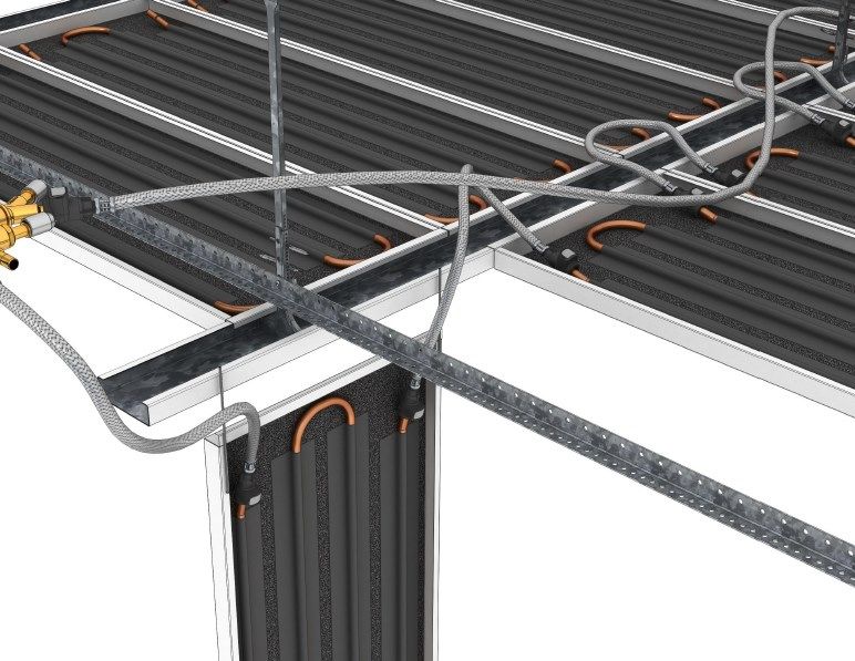
8.1.3 Deflection .................................................................................................................. 67
8.1.4 Camber of linear panels............................................................................................. 68
8.1.5 Squareness of membranes........................................................................................ 68
8.2 Corrosion protection ............................................................................................................... 69
8.3 Visual assessment of the surface ........................................................................................... 69
9 Declaration of performance and CE marking...................................................................... 70
9.1 Declaration of performance (DoP) .......................................................................................... 70
9.2 CE-Marking............................................................................................................................. 72
TMMC – Metal ceiling systems page 5 of 83 Edition January 202110 Environmental Product Declarations .................................................................................. 75
11 Packing, transport and storage ........................................................................................... 75
12 Installation............................................................................................................................. 75
12.1 General................................................................................................................................... 75
12.2 Installation instructions............................................................................................................ 76
12.2.1 Requirement of strucural parts................................................................................... 76
12.2.2 Flatness tolerances ................................................................................................... 76
12.2.3 Installation sequence ................................................................................................. 76
12.2.4 Alignment .................................................................................................................. 76
12.2.5 Absence of twisting.................................................................................................... 76
12.2.6 Alignment of the substructure .................................................................................... 76
12.2.7 Built-ins, built-ons, add-ons ....................................................................................... 76
12.3 Surfaces ................................................................................................................................. 77
12.3.1 Batch dependency ..................................................................................................... 77
12.3.2 Directionality .............................................................................................................. 77
12.4 Special features of linear panels ............................................................................................. 77
12.4.1 Flatness at the perimeter ........................................................................................... 77
12.4.2 Linear panel connections ........................................................................................... 77
12.4.3 Squareness, thermal expansion, additional loads, special areas ............................... 77
13 Maintenance and operation.................................................................................................. 78
13.1 Service life requirements (maintenance) ................................................................................. 78
13.2 Cleaning ................................................................................................................................. 79
14 Disposal................................................................................................................................. 79
15 National annex Germany ...................................................................................................... 80
15.1 Smoke leakage ....................................................................................................................... 80
16 Technical terms English - German ...................................................................................... 81
17 Revision history .................................................................................................................... 82
TMMC – Metal ceiling systems page 6 of 83 Edition January 20211 Foreword Whether it is a new building or a refurbishment, construction products that are designed for health, safe use and sustainability are a must in every modern building. Metal ceiling systems are considered sustainable building products which are particularly distinguished by their positive environmental and health-relevant characteristics. Aesthetic, economic and technological durability as well as architectural freedom of design are among the most important positive qualities. Its ease of maintenance allows a durable, flexible and economic use of buildings. A high degree of prefabrication on an industrial basis, with a corresponding level of quality, enormous resistance to mechanical influences and the highly respected long product life cycle are important plus factors. Members of the TAIM e.V. undertake in all points of the TMMC "Technical Manual for Metal Ceiling Systems" to comply with the specified minimum quality level, which goes beyond the normative requirements depending on the degree of utilization. The TAIM members demonstrate through the TAIM certification procedure that the quality requirements according to TAIM are met. Only members of TAIM e.V. are entitled to use the brand name and logo. The TMMC is intended for users who have general building expertise. It is assumed that users of the TMMC are familiar with the general technical regulations and standards. This TMMC cannot handle all details and does not free users from complying with national regulations. All information is given to the best of our knowledge, but without guarantee of the TAIM e.V. The technical descriptions of the system manufacturers are binding. This TMMC is constantly being supplemented and developed in line with technical progress. The editorial team is grateful for suggestions and constructive criticism and always endeavors to take them into account. The current version is published at www.taim.info. TMMC – Metal ceiling systems page 7 of 83 Edition January 2021
2 Scope
The "TMMC - Technical Manual Metal Ceiling Systems" provides the basics which are to be considered
for the planning and the use of metal ceiling systems as well as cladding elements of metal and their
composites according to TAIM.
This guide is meant to be of assistance to metal ceiling systems, but does not fully reflect all existing
national and European directives, regulations and standards.
In this TMMC, "requirements, test methods and terms related to metal ceiling systems" are treated
more succinctly than e.g. in various European standards as well as in the harmonized EN 13964
"Suspended ceilings - requirements and test methods" applicable to all ceiling systems.
The provisions of the TMMC are private law agreements and define the quality and state of the art of
metal ceiling systems falling within the scope of application described therein.
Examples of typical applications:
Office and administrative buildings
Airports, train stations, schools, hospitals
Shops, shopping malls, meeting places
Sports halls, swimming pools
Work shops, factories with production areas, laboratories
Residential- and hotel areas
The TMMC
applies to factory-made, industrially produced modular ceiling systems made of metal and
composite materials with and without edge upstands which are placed on the market with the
appropriate substructure components, individually or as a kit, optionally also with inlays and lay-
on pads and/or installed items from system-compatible components.
regulates requirements and test methods for complete metal ceiling systems in interior and
exterior which are horizontally installed.
For inclined or curved surfaces, additional requirements shall be specified by the building
designer.
contains information for the various properties, for the design, manufacture, definition and
selection of metal ceiling systems.
TMMC – Metal ceiling systems page 8 of 83 Edition January 20213 Normative references
Standard-No. Title
EN ISO 354 Acoustics - Measurement of sound absorption in a reverberation room
DIN 971-1 Fasteners – Stud bolts – Part 1: Metric thread
EN 1264-4 Water based surface embedded heating and cooling systems – Part 4: Installation
EN 1991-1-4 Eurocode 1: Actions on structures - Part 1-4: General actions - Wind actions
EN 1998-1 Eurocode 8: Design of structures for earthquake resistance- Part 1: General rules, seismic actions
and rules for buildings
EN ISO 2081 Metallic and other inorganic coatings – Electroplated coatings of zinc with supplemetary treatments
on iron or steel
EN ISO 2813 Paints and varnishes - Determination of gloss value at 20°, 60° and 85°
DIN 4726 Warm water surface heating systems and radiator connecting systems - Plastics piping systems and
multilayer piping systems
EN ISO 7599 Anodizing of aluminum and its alloys - Method for specifying decorative and protective anodic
oxidation coatings on aluminum
EN ISO 9223 Corrosion of metals and alloys - Corrosivity of atmospheres - Classification, determination and
estimation
EN 10152 Electrolytically zinc coated cold rolled steel flat products for cold forming - Technical delivery
conditions
EN 10169 Continuously organic coated (coil coated) steel flat products - Technical delivery conditions
EN 10217-7 Welded steel tubes for pressure purposes - Technical delivery conditions - Part 7: Stainless steel
tubes
EN 10244-2 Steel wire and wire products – Non-ferrous metallic coatings on steel wire – Part 2: Zinc or zinc alloy
coatings
EN 10346 Continuously hot-dip coated steel flat products for cold forming – Technical delivery conditions
EN 10088-2 Stainless steels – Part 2: Technical delivery conditions for sheet/plate and strip of corrosion resisting
steels for general purposes
EN ISO 11654 Acoustics – Sound absorbers – Rating of sound absorption coefficients
EN 12020-2 Aluminum and aluminum alloys - Extruded precision profiles in alloys EN AW-6060 and EN AW-6063
- Part 2: Tolerances on dimensions and form
EN 12735-2 Copper and copper alloys – Seamless, round tubes for air conditioning and refrigeration - Part 2:
Tubes for equipment
EN ISO 12944-1 Paints and varnishes - Corrosion protection of steel structures by protective paint systems – Part 1:
General introduction
EN 13501-1 Fire classification of construction products and building elements - Part 1: Classification using data
from reaction to fire tests
EN 13501-2 Fire classification of construction products and building elements - Part 2: Classification using data
from fire resistance tests
EN ISO 13760 Plastic pipes for the conveyance of fluids under pressure - Miner's rule – Calculation method for
cumulative damage
EN 13964 Suspended ceilings - Requirements and test methods
EN 14037-1 Free hanging heating and cooling surfaces for water with a temperature below 120°C – Part 1: Pre-
fabricated ceiling mounted radiant panels for space heating – Technical specifications and
requirements
EN 14240 Ventilation for buildings - Chilled ceilings - Testing and rating
EN 15804 Sustainability of construction works - Environmental product declarations - Core rules for the
product category of construction products
EN ISO 16120-2 Non-alloy steel wire rod for conversion to wire – Part 2: Specific requirements for general purpose
wire rod
EN 16516 Construction products - Assessment of release of dangerous substances - Determination of
emissions into indoor air
ISO 17455 Plastic piping systems - Multilayer pipes - Determination of the oxygen permeability of the barrier
pipe
DIN 18182-1 Accessories for use with gypsum boards - Part 1: Steel plate sections
DIN 24041 Perforated plates - Dimensions
TMMC – Metal ceiling systems page 9 of 83 Edition January 20214 TAIM – certification procedure
TAIM's central quality tool is the specially developed TAIM company certification, which is the
prerequisite for membership in the Association of TAIM e.V.
The TAIM company certification encompasses a broad and in-depth range of quality criteria.
Within the framework of the certification process, business processes are examined which form the
basis for compliance with tolerances, including testing and evaluation procedures for material
procurement and quality of the raw materials. It also focuses on aspects such as fire protection, sound
insulation and mechanical strength as well as compliance with EN 13964 (suspended ceilings -
requirements and test methods).
The certification has to be carried out by all members every year. This ensures that the products of the
member companies have a consistently high level of quality. The TAIM certificate confirms successful
company certification of the members.
5 TAIM -compliant metal ceiling systems
Metal ceiling systems that meet the technical and legal requirements of the TAIM TMMC include the
following features / evidence:
1. Compliance with the technical requirements of the TMMC in its current version
2. Proof of conformity with standards in accordance with EN 13964 (CE marking / declaration of
performance)
3. Proof of TAIM company certification
4. Management of an EPD (Environmental Product Declaration according to ISO 14025 and EN
15804) for the metal ceiling system
6 Terms and definitions
In addition to the definitions of EN 13964, the following terms apply to TMMC.
6.1 Metal ceiling system
Metal ceiling as a finished product, which consists of the system manufacturer's specifically defined and
matched components.
For this purpose, the top fixing, suspension, the substructure, membrane and all to be considered
connecting parts.
Metal ceiling systems can at the same time meet different requirements; they fulfill the properties
guaranteed by the system manufacturer.
The minimum requirements of EN 13964 with the supplementary quality characteristics of the TAIM
shall be met.
TMMC – Metal ceiling systems page 10 of 83 Edition January 2021Non-metallic materials are included as far as approved by the system manufacturer. These may e.g. on the backside of the membrane loose or firmly connected, or be applied. The membrane is always aligned with its visible side to the room side. In addition to the classic horizontal alignment - depending on the manufacturer - special designs such as inclined, concave, convex, polygonal, ... are also possible. The metal membranes are usually individually removable and suitable for replacement. Although different manufacturers may have the same system designations and similar technical or even identical specifications, it should be noted that system parts from different manufacturers – even if they carry a CE marking - are not interchangeable and are not always designed to fit together. A = Soffit / Wall B = Top fixing (e.g. anchor / screw – not part of the system) C = Suspension D = Secondardy profile E = Primary profile F = Membrane G = Perimeter trim Fig. 1 - General system design parts TMMC – Metal ceiling systems page 11 of 83 Edition January 2021
6.1.1 Hook-on systems
Metal ceiling systems, whose membranes are mounted on a non-visible or only partially visible
substructure.

 Fig. 2 – Example for a hook-on system                  Fig. 3 – Example for a double hook-on system

 Fig. 4 – Example for a hook-on system                  Fig. 5 – Example for a hook-on T profile system
          at the perimeter

6.1.2 Clip-in systems

Clip-in systems
Metal ceiling systems, whose membranes are clipped into a non-visible or only partly visible
substructure.

 Fig. 6 – Example for a clip-in system with a           Fig. 7 – Example for a clip-in system with
          non-visible profile                                    perimeter trim

TMMC – Metal ceiling systems                    page 12 of 83                                Edition January 2021
Clip-in swing-down system Metal ceiling systems, whose membrane elements are clipped on to a concealed or only partly covered substructure and which can individually be swung-down. Cut or special size membranes can generally not swing-down. The membranes are held in the swing-down position by special retaining lugs to the substructure. The membranes can be moved in the folded state. Fig. 8 – Example for a clip-in and swing-down system 6.1.3 Post-cap systems Linear installation – Post-cap visible Metal ceiling systems whose visible post-cap profiles form a linear geometry. The membranes can be produced as lay-on, lay-in, hook-on, clip-in or removable system. If equipped with special hinging and locking elements, the membranes can be swiveled or folded down over their sides or longitudinal axes. Also movable swing-down membranes are possible. The post-cap profiles have a width of 50 to 300 mm and are - depending on the specifications of the system manufacturer - suitable for fixing partitions. Fig. 9 – Example for a C-post-cap system Fig. 10 – Example for a lay-on post-cap system TMMC – Metal ceiling systems page 13 of 83 Edition January 2021
Cross post cap system with – Post cap visible
The visible post cap profiles are usually arranged in a square or rectangular design.

 Fig. 11 – Example for a Cross post cap system           Fig. 12- Example for a cross post cap system
           Top view                                               suspension.

Cross post cap system – Post cap visible – with crossing boxes
The visible post-cap profiles are designed for a mostly square or rectangle-oriented geometry. At the
intersections, crossing boxes are installed as a separate component or as an optical node.

Fig. 13 – Example for a cross post cap system with crossing boxes

TMMC – Metal ceiling systems                     page 14 of 83                               Edition January 2021
6.1.4 Tile ceiling system
Metal ceiling systems mit square membrane elements.
Fig. 14 – Example for a lay-in tile with L-turn-up Fig. 15 – Example for a lay-in tile with Z-turn-up
Fig. 16 – Example for a clip-in tile Fig. 17 – Example for a clip-in swing-down tile
with L-upstands on 4 sides with L-upstands on 4 sides
6.1.5 Lay-in- / Lay-on systems
Metal ceiling systems, whose membranes are laid in or on a visible substructure.
Fig. 18 – Example for a lay-on system Fig. 19 – Example for a lay-in system
T-profile construction with lay-on T-Profile construction with lay-in
membrane membrane
TMMC – Metal ceiling systems page 15 of 83 Edition January 20216.1.6 Swing-down systems
Metal ceiling systems, whose membranes can be swung down over the longitudinal or short sides.
The membranes have either specially shaped retaining lugs or swing & latch components attached to
them. During swinging down, the membranes are connected to the substructure. The hinging and
locking elements can be visible or hidden.
Depending on the design, the membranes can be moved in the folded-down state.
Fig. 20 - Example for a post cap ceiling with swing-down and movable membrane
Fig. 21 - swing direction over long side of the Fig. 22 - swing direction over long side of the
membrane - in the same direction membrane - in opposite directions
TMMC – Metal ceiling systems page 16 of 83 Edition January 2021Fig. 23 - swing direction over short sides in the
same direction
6.1.7 Inspection hatches
Components of the substructure and/or membrane, which are equipped with an access facility so that
certain parts of the membrane can be removed or opened and access to the substructure and/or the
ceiling cavity is possible.
Metal ceilings are usually designed so that the membrane can be removed individually and are suitable
for reuse.
There are many variants available, depending on the manufacturer and the system:
a) tool-free dis- & re-assembly of the membrane (by removing ..)
b) dis- & re-assembly only with tools
c) membrane equipped with additional bearing and locking parts for swing-down, moving ...
d) membranes with shut-off devices
e) membranes with additional measures such as safety ropes
f) inspection flaps fit to the respective system
Inspection hatches are also subject to the minimum requirements of EN 13964 (safety in the event of
fire - acoustics - mechanical strength - heating/cooling technology...).
TMMC – Metal ceiling systems page 17 of 83 Edition January 20216.1.8 Ceiling islands Individual randomly arranged metal ceilings in the room without any connection to the adjacent walls are usually called ceiling islands. Ceiling islands are a special form of suspended ceilings, but from the point of view of TAIM they are always to be regarded as ceilings within the scope of EN 13964. Ceiling panels can be fixed directly to the soffit (even without a substructure) or suspended from the soffit. The peripheral edges can be formed in different shapes or bordered with additional frame profiles. If individual ceiling panels are mounted side by side, a clear distinction between "ceiling island" and "suspended ceiling" and a "closed / or open ceiling" is not possible. Fig. 24 - Example for a ceiling island TMMC – Metal ceiling systems page 18 of 83 Edition January 2021
6.1.9 Double-walled baffle systems
Are metal ceiling systems with vertically arranged double-walled membranes.
Both vertical sides and the lower side view to the room side are formed as visible sides.
Depending on the type of installation, the end of the baffles can be designed either open or closed.

 Fig. 25 - Example for a baffle ceiling

 Fig. 26 – Example for a double-walled baffle             Fig. 27 – Example for a double-walled baffle
           made from bent or roll formed metal.                     made from extruded aluminium

TMMC – Metal ceiling systems                      page 19 of 83                                Edition January 2021
6.1.10 Single-walled baffle systems
Are Metal ceiling systems with vertically arranged single-walled membranes.
Both sides are designed to be visible.
Unless otherwise indicated, the edges of the material are not coated.
Fig. 28 - Example for a single-walled baffle ceiling Fig. 29 - Example for a single-walled baffle
with main runner
6.1.11 Linear panel systems
Are metal ceiling systems with linearly arranged membranes mostly with the ends open.
Linear panel ceilings have membranes with a width up to max. 400 mm, which are turned up on the two
longitudinal sides and whose length corresponds to a multiple of the width.
By means of longitudinal connectors, panels can also be laid as "endless panels".
The membranes are connected by clamps, clips or as suspension systems with the substructure.
Fig. 30 - Example for a linear panel system Fig. 31 – Example for a linear panel system
with open joint with closed joint
TMMC – Metal ceiling systems page 20 of 83 Edition January 2021Fig. 32 – Example for a linear panel system Fig. 33 - Example for a linear panel system
with a closed joint with infill strip
6.1.12 Open cell systems
Open cell ceiling systems consisting of single-walled or double-walled membranes arranged in a cross-
connection. The vertically arranged membranes are connected at an angle of 90 degrees as an element
to each other. Both vertical surfaces are designed as visible sides.
Fig. 34 - Example for a double-walled open Fig. 35 - Example for a single-walled open cell
cell system system
the lower visible edge is usually the lower visible edge is usually not
coated coated
TMMC – Metal ceiling systems page 21 of 83 Edition January 20216.1.13 Expanded metal ceiling systems
Are metal ceiling systems with a membrane of expanded metal mesh.
Expanded metal consists of sheets of semi-finished products, with openings in the surface, which are
produced by stretching metal sheets with staggered cuts causing deformation without any loss of
material. The edges may be factory-machined, e.g. with stiffening frame profiles.
In the case of expanded metal ceiling panels, the panel length is usually 90 ° offset from the mesh
length.
Depending on the system, concealed or visible welds are used for expanded mesh membranes.
Sharp edges can occur when the material is cut.
To avoid injury, wear suitable protective equipment.
Fig. 36 - Example for an expanded metal tile Fig. 37 – Example for an expanded metal
with internal frame sheet
sheet length and width
TMMC – Metal ceiling systems page 22 of 83 Edition January 20216.1.14 Composite elements
Metal membranes with at least one additional layer (thickness ≥ 3 mm / weight ≥ 150 g/m²), in which the
different layers are connected.
Inlays or pads may also be non-metallic materials.
Metal membranes with tissue (inserted or glued in) are not to be considered as composite elements.
Fig. 38 – Example for a metal composite element Fig. 39 - Example for a metal composite element
with inlay with lay-on
Fig. 40 - Example for a metal composite element
consisting of aluminium honeycomb
centre with sheet metal covering on both
sides
TMMC – Metal ceiling systems page 23 of 83 Edition January 20216.2 Heating and cooling ceiling systems 6.2.1 Heating-/cooling medium Water-run heating and cooling ceiling systems made of metal are ceiling systems with water-carrying tubes installed on the back of the metal membrane, including the required connection and distribution tubes within a room up to the control valves. The flow temperature is to be coupled to a dew point control system. Depending on the required heating / cooling capacity, the heating / cooling ceiling usually consists of active and passive membranes, both belonging to the heating / cooling ceiling forming a system. Additional air ducts can be used, to supply the room with or without pre- treated air, or used to remove exhaust air. Fig. 41 - Example for a post-cap ceiling with heating and cooling elements TMMC – Metal ceiling systems page 24 of 83 Edition January 2021
PCM (Phase Changing Materials)
 Cooling ceilings of this type are equipped with storable PCM. The passively absorbed
 heat during the day is dissipated during the following night with significantly lower
 energy consumption.

Thermal active component systems (TABS)
Are metal ceiling systems that use the storage capacity of the buildings concrete soffit.
The heat exchange between the soffit and the room is carried out by the type of attachment of the
substructure and membranes and the nature and type of installation.

Membranes can additionally be equipped as active cooling ceiling elements.

 Fig. 42 – Example for a thermal active ceiling island (tabs)

6.2.2 Active and passive elements
Heating and cooling ceiling systems consist of active and passive areas, which as a whole form a
suspended surface for the heating and cooling ceiling systems.

Active elements:
Metal ceiling membranes with integrated heating / cooling system on the back.

Passive elements:
Metal ceiling membranes that together with active elements form a ceiling surface.
The passive element fulfills the same properties as the active element with regard to fire behavior and
sound insulation.

Retrofit options for active and passive membranes shall be agreed with the system manufacturer.

TMMC – Metal ceiling systems                    page 25 of 83                              Edition January 2021
6.2.3 Tubing
A tubing consists of heat-conducting profiles and meandering tube, which are interconnected. It consists
of at least two rows of tubes in connection with the heat-conducting profiles. Axial spacing and
geometry differ manufacturer-specific.
Unless otherwise stated, it is up to the system manufacturer to determine the direction, number,
modules and dimensions, as well as the type of fixing in the membranes.

 Fig. 43 - Example for a tubing for heating and cooling ceiling consisting of heat conduction profiles and
 pressed-in tubes

The tubing is introduced in different ways to the back of the membrane, depending on the requirements
and the system manufacturers.

The most commonly used techniques are:
a) loosely inserted frets, optionally with securing elements
b) Frets adhered to back of membrane
c) frets with integrated magnetic strips

 Fig. 44 - Example for an active metal ceiling membrane for heating and cooling with applied tubing.

TMMC – Metal ceiling systems                   page 26 of 83                               Edition January 2021
6.2.4 Heat conducting profile
Heat-conducting profiles are usually made of aluminum or steel profiles, which are placed on the back of
the metal ceiling membrane intended to fix the water-carrying tubes. The heat-conducting profiles help
to transfer the heat/cold from the water medium to the metal surface of the membrane.
The heat-conducting profiles may vary in size, dependent on the manufacturer.

 Fig. 45 - Example for a conducting profile with       Fig. 46 - Example for a conducting profile with
           tube fixing                                           tube fixing and magnetic strip

6.2.5 Meander
Meanders consist of at least two rows of tubes usually S- or serpentine shaped, made from copper or
stainless steel tubes, oxygen diffusion-tight plastic pipes or multi-layer composite pipes; outer diameter
of the tubes from approx. 6 mm to approx. 15 mm. The meanders are usually pressed into the
conducting profiles to improve heat transfer.

a) Copper tubes
Usually copper tubes acc. to EN 12735-2 standard are used for this purpose.

b) Stainless steel tubes
Welded tubes made of stainless steel acc. to EN 10217-7 standard.

c) Plastic- und multi-layer composite tubes
Pipe meanders using plastic or multi-layer composite tubes, which are oxygen-impermeable, can be
used as an alternative acc. to DIN 4726 / EN ISO 13760 / ISO 17455 standards.

 Fig. 47 - Example for a meander with 4 bars / both end bars are bent upwards.

TMMC – Metal ceiling systems                   page 27 of 83                               Edition January 2021
6.2.6 Meander in thermally conductive inserts Meanders may be incorporated in highly heat-conductive materials, such as e.g. graphite, pressed or embedded in. These elements are used on the back side in metal membranes. Fig. 48 - Example for a pre-fabricated membrane with embedded meander 6.2.7 Capillary tube mats Plastic tube mats with an outside diameter of about 4 mm to about 8 mm. The individual plastic capillary tubes are usually connected to the front sides by means of a straight supply and return tube. Capillary tube mats on the back of the membrane are a) Laid in or b) Glued in or c) Additionally secured by special brackets. Fig. 49 - Metal ceiling membrane with laid in capillary tube mats TMMC – Metal ceiling systems page 28 of 83 Edition January 2021
6.2.8 Connection and distribution conductions
Connecting and distributing conductions can be made of plastic tubes, stainless steel covered hoses,
stainless steel hoses or also from multi-layer composite tubes.

a) Supply pipes
   are used to connect the active heating / cooling ceiling elements to the distributor.
b) Connection pipes
   provide the hydraulic connection of two active elements.
c) Distributors / manifold bars / Supply pipes
   water the individual fields with heating or cooling medium.
d) Distributors / manifold bars / Return pipes
e) Regulating valve
f) Shut-off valve

 Fig. 50 - Example for a connection of active heating ceiling tiles

6.2.9 Plug in connectors
Plug in connectors - usually detachable - are used to connect to supply lines and / or connect to with
other meanders and / or the return pipes.

6.2.10 Heating- or cooling fields
A heating or cooling field consists of one or more active elements, which are connected together in
series. Passive elements may also be included In between active elements.

6.2.11 Control area
A control area consists of one or more heating or cooling fields, which are connected in parallel.
The control areas are usually selected by room or axis.
The size of the control areas is limited by the regulation unit.

TMMC – Metal ceiling systems                    page 29 of 83                              Edition January 2021
6.3 Metal ceiling membrane
Thin gauge metal component up to a nominal thickness of 3 mm, which forms the visible surface of the
suspended ceiling, provided that this is not a visible part of the substructure.
Metal ceiling panels are membranes with usually 4-sided turned up edges.

If not explicitly determined by the system manufacturer, the membrane is not designed to support
other loads.

6.3.1 Functional upstands
A functional upstand is the edge of the membrane which establishes the non-positive or positive
connection to the substructure.

6.3.2 Stabilization upstands
Upstands that do not serve as a non-positive or positive connection to the substructure.
The upstands can also be designed differently for the same panel dimensions in terms of geometry and
dimensions.

TMMC – Metal ceiling systems                 page 30 of 83                             Edition January 2021
6.3.3 Membrane upstands
The edge shape is determined by the system manufacturer.
The edge surfaces are only designed as a visible side if separately agreed.

Table 1 – Examples for metal ceiling membranes / tiles edge details
    No.                        Description                          Sketch

     1        L-upstand

     2        L-upstand with bevel

     3        C-upstand

     4        Hook on upstand „Type A“

     5        Hook on upstand „Type B“

     6        Z-upstand

     7        L-upstand with hinge or latch

TMMC – Metal ceiling systems                   page 31 of 83                  Edition January 2021
Table 2 – Examples for expanded metal ceiling edge details
No. Description Sketch
1 Expanded metal with edge protection
2 Expanded metal with pressed edge
Expanded metal
3
with interior frame
Expanded metal
4
with external frame
Expanded metal
5
with top mounted frame
Expanded metal
6
with side mounted frame
Table 3 - Examples for linear panel edge details
No. Description Sketch
1 C-upstand with bead
2 F-upstand with bead
3 C-upstand
4 C-upstand with double bead
5 R-upstand
TMMC – Metal ceiling systems page 32 of 83 Edition January 20216.3.4 Joint types
Table 4 – Examples for typical joints
No. Description Sketch
1 without bevel
2 with bevel
3 with gap
4 with distancing pieces
5 with gasket
6 with step
7 with infill strip
8 with closed joint
TMMC – Metal ceiling systems page 33 of 83 Edition January 20216.3.5 Ropes as operating and assembly aid
a) Ropes, which limit the pivoting range of the panel when folding down the ceiling panels
b) Ropes, which are used in removable ceiling panels for suspending the ceiling panels.
They are not safety parts and - unless otherwise stated - are not designed for dynamic loads.
Depending on the panel dimensions, reinforcements in the ceiling panels and/or in the area of the
substructure are recommended.
If not specified by the system manufacturer, ropes and possible strengthening measures are to be agreed
upon.
6.4 Substructure
An essential part of the finished product consisting of system-specifically defined metal components as
intended for a system defined by the system manufacturer.
The substructure is to be designed for installing the membrane element and has to bear the entire dead
load of the system together with the expected dead load of the membrane.
The information provided by the system manufacturer shall be observed.
The number of fixing points shall be such that the permissible load capacity of the anchors is not
exceeded.
For this purpose, suspension, substructure profiles and all connecting parts are to be considered.
Unless specifically stated by the system manufacturer, the substructure is not designed to carry extra
loads, e.g. partitions, installed items or parts, cables, lights etc.
The minimum requirements of EN 13964 shall be met.
TMMC – Metal ceiling systems page 34 of 83 Edition January 20216.4.1 Profiles
The geometries are manufacturers own design with different characteristics.
Table 5 – Examples for different ceiling profiles:
Section Description Abbreviation
A C-Ceiling profile CD-Profile (DIN 18182-1)
U-Ceiling profile UD-Profile (DIN 18182-1)
U- reinforcing section UA-Profile (DIN 18182-1)
B
U-Wall floor/ceiling profile UW-Profile (DIN 18182-1)
U-Profile U-Profile
C C-Dry wall stud CW-Profile (DIN 18182-1)
D Lay-on post cap AB-Profile
E C-Post cap CB-Profile
F G-Post cap GB-Profile
G C-Post cap with groove CN-Profile
H Hook on profile E-Profile
TMMC – Metal ceiling systems page 35 of 83 Edition January 2021Continuation of Table 5 - Examples for different ceiling profiles
Section Description Abbreviation
I Double hook-on profile DE-Profile
J G-Profile G-Profile
K Clip-in profile K-Profile
L T-profile T-Profile
M T-Hook-on profile TE-Profile
N V-Profile V-Profile
O U-Carrier profile U-Carrier profile
P Linear panel-carrier profile Carrier profile
TMMC – Metal ceiling systems page 36 of 83 Edition January 20216.4.2 Suspension
Are parts of the substructure which are connected to the load-bearing components from the soffit.
Since the soffits always vary so do the top fixings, anchors and the like are not considered as part of the
suspension. If the fixing used is not approved by the system manufacturer, it is the installers
responsibility to test and certify it.
Table 6 - Examples for non-pressure-resistant suspension options
Fig. 51 – quick adjustment hanger Fig. 52 – Nonius upper- / lower section with
one safety splint
Table 7 – Examples for pressure-resistant options
Fig. 53 – Nonius upper- / lower section Fig. 54 - Nonius upper- / lower section
with two safety pins with unequal U-safety pin
Fig. 55 – Threaded rod Fig. 56 - Nonius upper- / lower section
with two safety splints
TMMC – Metal ceiling systems page 37 of 83 Edition January 20216.4.3 Top fixing Fixing such as anchor and/or screws, which connects the hanger or substructure with the load-bearing component (soffit). 6.4.4 Suspension height Suspension height is the total height of the metal ceiling system viewed from the lower edge of the soffit to the lower edge of the membrane surface visible from the room. 6.4.5 Connector Fastening part intended to connect the hanger and substructure parts. 6.4.6 Primary grid Substructure which is connected to the soffit and is designed either for the fixing of the secondary grid or to carry the membranes. 6.4.7 Secondary grid/carrier profiles Substructure which is connected to the primary grid and designed to carry the membranes. TMMC – Metal ceiling systems page 38 of 83 Edition January 2021
6.5 Perimeter trims
Manufacturer-specific geometries are shaped with different characteristics.

Table 8 – Examples for typical perimeter trims

                       Section                       Description              Abbreviation

                                      L-Trim – unequal lengths            Lu-Profil
    A

                                      L-Trim – equal lengths              Lg-Profil
    B

                                      W-Trim with shadow gap              Ls-Profil
    C

                                      F-Trim                              Fr-Profil
    D

                                      W-Trim with shadow gap              Fs-Profil
    E

                                      U-Perimeter trim
    F                                                                     Ur-Profil

6.5.1 Load bearing perimeter trim
Perimeter trim between membrane/substructure and enclosure walls.
Load-bearing perimeter trims are designed to bear the load of the substructure and/or the membranes.

6.5.2 Non load-bearing perimeter trim
Perimeter trims between membrane/substructure and enclosure walls.
Non-load-bearing perimeter trims are not designed to bear the load of the substructure or membranes.

TMMC – Metal ceiling systems                     page 39 of 83                         Edition January 2021
6.6 Perforations
Penetrations of the membrane with different shapes, dimensions and distance to each other.
Micro perforations are perforations with a diameter ≤ 1 mm.
6.7 Axial dimension
The axial dimension of the membrane is the nominal size including 2x the nominal half joint dimension.
The axial dimension of modular grid ceilings is the distance from post cap center to center.
A A
Fig. 57 - Axial dimension of a membrane Fig. 58 - Axial dimension of a post-cap ceiling
6.8 Module dimension of membrane
Is the nominal size of the membrane plus the nominal joint width.
A
Fig. 59 - Module dimension of a membrane
TMMC – Metal ceiling systems page 40 of 83 Edition January 2021You can also read