Installation Manual FC-Series - FC-Series S FC-Series R
←
→
Page content transcription
If your browser does not render page correctly, please read the page content below
Installation
Manual
FC-Series

           FC-Series S
           FC-Series R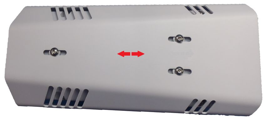
© 2014 FLIR Systems, Inc. All rights reserved worldwide. No parts of this manual, in whole or in part, may be
copied, photocopied, translated, or transmitted to any electronic medium or machine readable form without the
prior written permission of FLIR Systems, Inc.
Names and marks appearing on the products herein are either registered trademarks or trademarks of FLIR
Systems, Inc. and/or its subsidiaries. All other trademarks, trade names, or company names referenced herein are
used for identification only and are the property of their respective owners.
This product is protected by patents, design patents, patents pending, or design patents pending.
The contents of this document are subject to change.
FLIR Systems, Inc.
70 Castilian Drive
Goleta, CA 93117
Phone: 888.747.FLIR (888.747.3547)
International: +1.805.964.9797
http://www.flir.com

Important Instructions and Notices to the User:
Modification of this device without the express authorization of FLIR Commercial Systems, Inc. may void the user’s
authority under FCC rules to operate this device.
Note 1: This equipment has been tested and found to comply with the limits for a Class B digital device, pursuant to
Part 15 of the FCC rules. These limits are designed to provide reasonable protection against harmful interference
in a residential installation. This equipment generates, uses, and can radiate radio frequency energy and, if not
installed and used in accordance with the instructions, may cause harmful interference to radio communications.
However, there is no guarantee that the interference will not occur in a particular installation. If this equipment does
cause harmful interference to radio or television reception, which can be determined by turning the equipment off
and on, the user is encouraged to try to correct the interference by one or more of the following measures:
• Reorient or relocate the receiving antenna;
• Increase the separation between the equipment and receiver;
• Connect the equipment into an outlet on a circuit different from that of the receiver; and/or
• Consult the dealer or an experienced radio/television technician for help.
Note 2: This equipment was tested for compliance with the FCC limits for a Class B digital device using a shielded
cable for connecting the equipment to an analog video output to a monitor and using a shielded USB cable for
connecting the equipment to a personal computer. When making such connections, shielded cables must be used
with this equipment.
Industry Canada Notice:
This Class B digital apparatus complies with Canadian ICES-003.
Avis d’Industrie Canada:
Cet appareil numérique de la classe B est conforme à la norme NMB-003 du Canada.

Proper Disposal of Electrical and Electronic Equipment (EEE)
                 The European Union (EU) has enacted Waste Electrical and Electronic Equipment Directive 2002/96/EC
                 (WEEE), which aims to prevent EEE waste from arising; to encourage reuse, recycling, and recovery of EEE
                 waste; and to promote environmental responsibility.
                   In accordance with these regulations, all EEE products labeled with the “crossed out wheeled bin” either on the
                   product itself or in the product literature must not be disposed of in regular rubbish bins, mixed with regular
                   household or other commercial waste, or by other regular municipal waste collection means. Instead, and in
                   order to prevent possible harm to the environment or human health, all EEE products (including any cables that
came with the product) should be responsibly discarded or recycled.
To identify a responsible disposal method where you live, please contact your local waste collection or recycling service, your
original place of purchase or product supplier, or the responsible government authority in your area. Business users should
contact their supplier or refer to their purchase contract.
Document History
Version  Date                 Comment
100      April 2014           Initial Release
110      June 2014

427-0073-12-12 Version 110                         June 2014                                                   -ii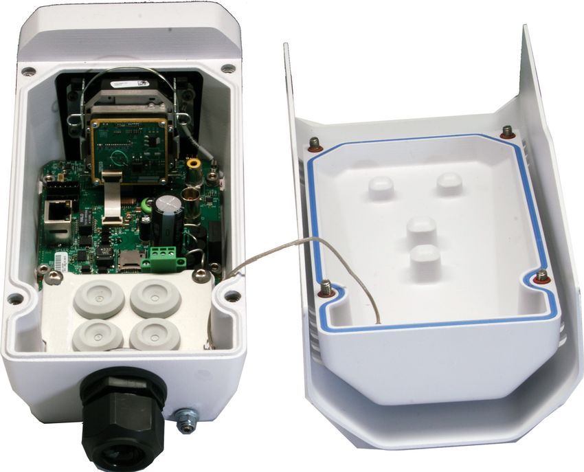
Table of Contents

Table of Contents

 Camera Installation
   1.1 Warnings and Cautions ............................................................................................ 1-1
   1.2 References ............................................................................................................... 1-1
   1.3 Installation Overview ................................................................................................. 1-2
       1.3.1 Camera Connection Options ............................................................................ 1-2
              General Purpose Input/Output (GPIO) ............................................................. 1-2
              PoE+ Power Supplies ...................................................................................... 1-2
       1.3.2 Camera Accessories ........................................................................................ 1-3
       1.3.3 Supplied Components ..................................................................................... 1-3
       1.3.4 Required Supplies ........................................................................................... 1-3
   1.4 Location Considerations ........................................................................................... 1-3
       1.4.1 Bench Testing .................................................................................................. 1-4
       1.4.2 Prior to Cutting/Drilling Holes ........................................................................... 1-4
       1.4.3 Camera Mounting for Rear Cable Access ........................................................ 1-4
       1.4.4 Camera Mounting with Concealed Cable Wall Mount ...................................... 1-6
       1.4.5 Sunshield ......................................................................................................... 1-6
   1.5 Removing the Cover ................................................................................................. 1-7
   1.6 Camera Connections ................................................................................................ 1-7
       1.6.1 Configuring the Lens Heater Jumper ............................................................... 1-8
       1.6.2 Analog Video Connections ............................................................................... 1-9
       1.6.3 Connecting Power ........................................................................................... 1-9
       1.6.4 Ethernet ......................................................................................................... 1-10
       1.6.5 GPIO Connections ......................................................................................... 1-10
       1.6.6 Camera Grounding ........................................................................................ 1-11
   1.7 Rear Access Cable Gland Sealing .......................................................................... 1-11
   1.8 Concealed Cable Mount Accessory ........................................................................ 1-13
   1.9 Camera specifications ............................................................................................ 1-15
 Basic Operation and Configuration
   2.1 Basic Test and Configuration Steps .......................................................................... 2-1
   2.2 Camera Bench Test .................................................................................................. 2-1
   2.3 Web Browser Interface ............................................................................................. 2-2
       2.3.1 Live Video Page ............................................................................................... 2-3
             Temperature—FC-Series R camera only ........................................................ 2-4
             Camera Control and Status ............................................................................. 2-4
             Web Control Panel .......................................................................................... 2-4
   2.4 Basic Camera Configuration ..................................................................................... 2-6
       2.4.1 Setup Menu ..................................................................................................... 2-6
       2.4.2 Server Menu .................................................................................................... 2-6
             Services Menu ................................................................................................. 2-8
   2.5 Thermal Imaging Overview ..................................................................................... 2-12
   2.6 Troubleshooting Tips .............................................................................................. 2-14
   2.7 Setting the IP address on a Windows PC ................................................................ 2-19

          427-0073-12-12 Version 110                       June 2014                                                   iii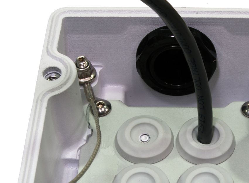
Table of Contents

Advanced Configuration
3.1 Setup Menu .............................................................................................................. 3-1
    3.1.1 Thermal Image Setup ....................................................................................... 3-2
          IR page ............................................................................................................ 3-2
    3.1.2 Video Analytics Setup ...................................................................................... 3-4
          Analytics page ................................................................................................. 3-4
    3.1.3 Temperature Monitoring Setup (FC-Series R camera only) ............................. 3-7
          Radiometry Page ............................................................................................. 3-7
3.2 Maintenance Menu ................................................................................................. 3-11
    3.2.1 Sensor Menu ................................................................................................. 3-11
          Communications Menu .................................................................................. 3-11
          Devices Menu ................................................................................................ 3-13
          Modules Menu ............................................................................................... 3-14
    3.2.2 Files Menu ..................................................................................................... 3-23
    3.2.3 Product Info Menu .......................................................................................... 3-25
3.3 Restoring the Factory Settings ................................................................................ 3-26

  Image from a standard camera in low light                             Image from a thermal camera in the same
                                                                                       conditions

    427-0073-12-12 Version 110                          June 2014                                                   iv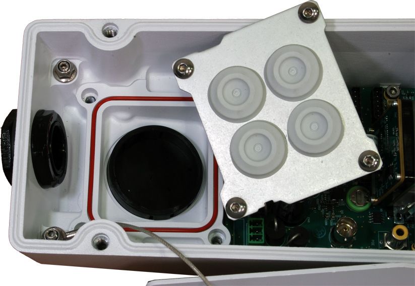
1   Camera Installation

    This manual describes the installation and initial configuration of the FC-Series IP thermal cameras,
    which includes the FC-Series S and FC-Series R camera models. These camera models are similar in
    design and the physical mounting and installation of both models is the same. The FC-Series R
    cameras have all the features of the FC-Series S plus an additional Radiometry feature that provides
    the ability to issue alarms based on temperature. If you need help during the installation process,
    contact your local FLIR service representative or, call 888-747-3547 inside the US.

    All installers and integrators are encouraged to take advantage of the training offered by FLIR; visit
    http://www.flir.com/training for more information.

    This manual includes the following topics:

    •     Installation overview
    •     Mounting the camera and its components
    •     Connecting the electronics
    •     Bench testing the camera
    •     Basic configuration and operation of the camera
    •     Camera Specifications

    For safety, and to achieve the highest levels of performance from the FC-Series camera system, always
    follow the warnings and cautions in this manual when handling and operating the camera.

    1.1       Warnings and Cautions
    Warning!

        If mounting the FC-Series camera on a pole, tower or any elevated location, use industry standard
        safe practices to avoid injuries.

    Caution!
        Except as described in this manual, do not open the FC-Series camera for any reason. Damage to
        the camera can occur as the result of careless handling or electrostatic discharge (ESD). Always
        handle the camera with care to avoid damage to electrostatic-sensitive components.
        Prior to making any connections, ensure the power supply or circuit breaker is switched off.
        Be careful not to leave fingerprints on the FC-Series camera’s infrared optics.
        Operating the camera outside of the specified input voltage range or the specified operating
        temperature range can cause permanent damage.

    1.2       References
    FLIR Doc # 427-00XX-XX-19S FC-Series S Interface Control Document (ICD), available on the
    documentation CD or from the FLIR website, provides further details regarding mechanical dimensions
    and mounting for the FC-Series camera.
    FLIR Doc # 427-0030-00-28 Nexus IP Camera Configuration Guide, provides more information on
    setting or changing camera parameters.
    These documents are provided for reference only.

    427-0073-12-12 Version 110               June 2014                                       1-1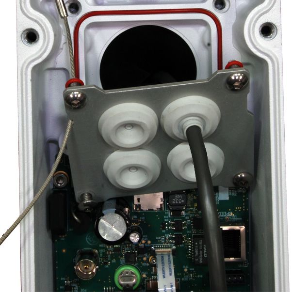
1   Camera Installation

    1.3     Installation Overview
    The FC-Series camera is an infrared thermal imaging camera intended for outdoor security
    applications, and can be installed in a fixed location or on a pan/tilt mechanism.The FC-Series
    camera is intended to be mounted on a medium-duty fixed pedestal mount or wall mount commonly
    used in the security industry. The camera mount must support up to 5 lbs (2.3 kg).

    Cables may exit from the back of the camera housing through the
    supplied cable gland or from the bottom of the camera housing when
    using the concealed cable wall mount (sold separately). A cable gland
    plug is supplied for the rear of the camera housing when cables are
    routed using the concealed cable wall mount.

    1.3.1     Camera Connection Options
    The FC-Series camera can be installed with an analog or digital (IP) video output (or both). Analog
    video will require a connection to a video monitor or an analog video matrix switch. The camera can
    be powered using Power over Ethernet Plus (PoE+) or with a conventional 24 V (ac or dc) power
    supply. For a PoE+ connection, an accessory PoE+ power supply (PN 4132391, also called a PoE+
    injector) is available if the camera is not connected to a PoE+ switch. The maximum Ethernet cable
    run is 100 meters including the PoE+ power supply. In installations using PoE+ power and IP video,
    only a single Ethernet cable from the camera is required.

    In installations using analog video and conventional power (24 Vac is commonly used in many
    installations), an RG59U coaxial cable and a three-conductor power cable are installed. It is
    recommended an Ethernet cable should also be installed for camera configuration, operation and
    troubleshooting. The FC-Series camera does not support serial communications.

    General Purpose Input/Output (GPIO)

    The camera can receive a single external “contact closure” input signal and can provide a single
    internal “contact closure” output signal. Refer to GPIO Connections, pg. 1-10.

    PoE+ Power Supplies

    With PoE+, camera power is delivered to the camera via the normal Ethernet cable via the camera’s
    standard RJ-45 Ethernet connector. The FC-Series camera is a Powered Device compliant with the
    IEEE 802.3at-2009 standard, known as PoE+ or PoE Plus. The FC-Series camera is also backward
    compatible with the older IEEE 802.3af-2003 standard.

    When connected to Power Sourcing Equipment compliant with the earlier, lower power IEEE 802.3af-
    2003 standard, the limited power available to the FC-Series camera will prevent the formation of frost
    and ice. However, the limited power available from 802.3af-2003 will not fully achieve the camera’s
    stated specification for de-icing from cold start when the external environment temperature is < 0 °C.
    In all other ways the camera will operate normally with Ethernet Powered Sourcing Equipment
    compliant to either IEEE PoE standard.

    427-0073-12-12 Version 110              June 2014                                     1-2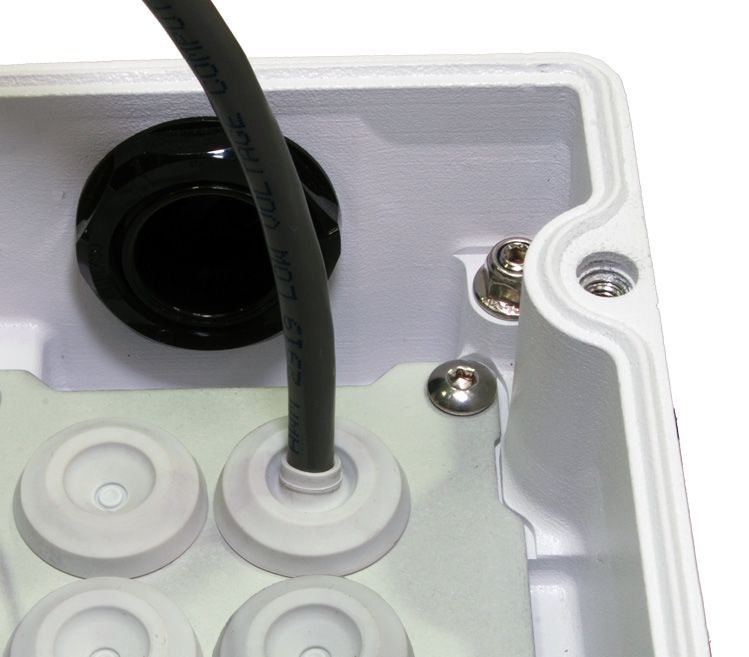
1   Camera Installation

    1.3.2       Camera Accessories
    The following accessories are available for purchase from FLIR Systems, Inc.

    •     PoE+ power supply (PN 4132391) - For powering a single FC-Series camera using PoE+. In
          addition to PoE+ power and communications, the power supply provides surge protection. It
          complies with IEEE 802.3at and is backward compatible with the IEEE802.3af standard.
    •     Concealed Cable Wall Mount (PN 4129742) - Includes camera mount gasket and hex wrench for
          adjusting the ball joint controlling the camera’s view angle.
          The FC-Series camera is attached to the mounting arm using the four M5 threaded bottom
          mounting holes. A cable gland plug is supplied with the camera for the rear of the camera housing
          when cables are routed using the concealed cable accessory. Refer to Camera Mounting with
          Concealed Cable Wall Mount, pg. 1-6 for installation instructions.
    •     Pole Mount Adapter Kit - (PN 4132982) - Adapter kit that allows the Concealed Cable Wall Mount
          to be mounted to a pole (75 mm [3 in] min to 180 mm [7 in]; larger pole diameter requires use of
          customer supplied band clamps)

    1.3.3       Supplied Components
    The FC-Series camera package includes these standard components:

    •     Fixed Camera Unit with sunshield and installed cable gland
    •     Cable gland plug and gland inserts for sealing camera housing
    •     Power terminal block plug
    •     Accessory terminal block plug
    •     Tools: 3 mm hex wrench (T-Handle), small blade screwdriver
    •     FC-Series Camera Documentation Package

    1.3.4       Required Supplies
    The installer will need to supply the following items as required (specific to the installation).

    •     Power cable if used for system power, 3-conductor, shielded, gauge determined by cable length
          and supply voltage
    •     PoE+ power supply or PoE+ switch if used for system power
    •     Cat5e Ethernet cable for digital video and/or PoE+ for system power
    •     Coaxial RG59U cables (BNC connector at the camera end) for analog video
    •     Camera grounding strap, camera mount, miscellaneous electrical hardware, connectors, and
          tools

    Be sure to use cables that fit in the cable gland holes, as described below. Refer to Rear Access
    Cable Gland Sealing, pg. 1-11 for more information.

    1.4       Location Considerations
    The camera will require connections for power and video. Ensure that cable distances do not exceed
    the specifications and that cables adhere to all local and industry standards, codes, and best
    practices. The FC-Series camera must be mounted upright, either on top of the mounting surface. or
    underneath an overhanging mounting surface such as eaves or an awning. The unit should not be
    mounted upside down.

    427-0073-12-12 Version 110                June 2014                                         1-3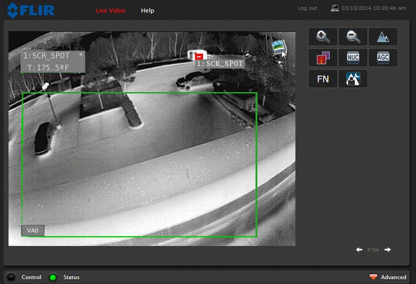
1   Camera Installation

    1.4.1     Bench Testing
    Note
     If the camera is to be mounted on a pole or tower or other hard-to-reach location, it may be a good
     idea to connect and operate the camera as a bench test at ground level prior to mounting the
     camera in its final location.

    Connect the power, Ethernet, and video, and confirm that the video can be displayed on a monitor
    when the power is turned on. For configuration and basic setup information using the onboard web
    server, refer to Camera Bench Test, pg. 2-1 for specific details.

    1.4.2     Prior to Cutting/Drilling Holes
    When selecting a mounting location for the FC-Series camera, consider cable lengths and cable
    routing. Ensure the cables are long enough, given the proposed mounting locations and cable routing
    requirements, and route the cables before you install the components.

    Use cables that have sufficient dimensions to ensure safety (for power cables) and adequate signal
    strength (for video and communications).

    1.4.3     Camera Mounting for Rear Cable Access
    The FC-Series camera can be secured to the mount with two in-line 1/4-20 threaded fasteners on the
    top or bottom of the camera. Alternatively the camera can be mounted with four M5 x 0.8 threaded
    fasteners to the bottom of the camera. Use Loctite 222 low strength threadlocker for the top mount
    fasteners (can be used with the bottom mount fasteners also). Refer to the FC-Series ICD for
    additional information.

    If using two 1/4-20 fasteners in the center of base, the maximum depth of the fastener should not
    exceed 12.5 mm (0.5 in). If using four M5 x 0.8 fasteners, the maximum depth of the fastener should
    not exceed 10.0 mm (0.4 in).

                          Figure 1-1: FC-Series Camera Bottom Mounting Holes

    427-0073-12-12 Version 110             June 2014                                      1-4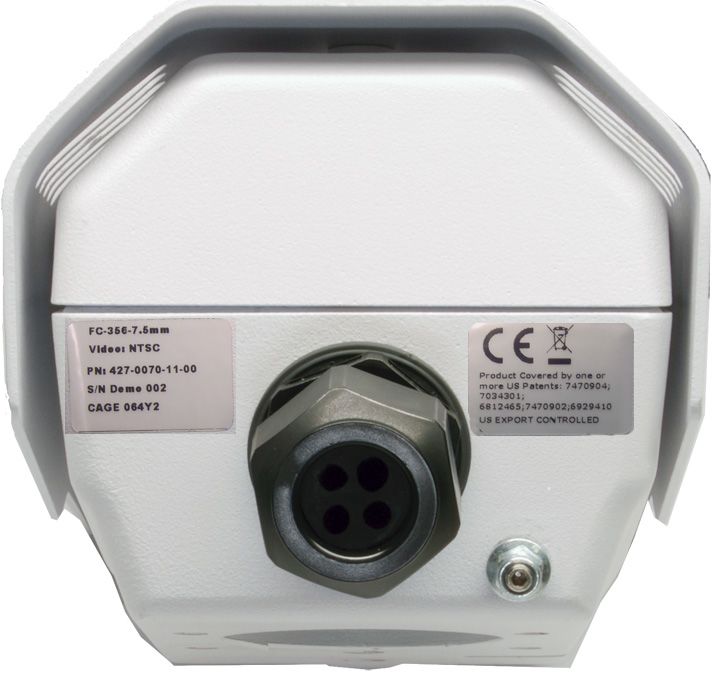
1   Camera Installation

                                    Figure 1-2: Top Side Mounting Holes

    If using two 1/4-20 fasteners in the center of top, the maximum depth of the fastener should not
    exceed 12.5 mm (0.5 in). If the camera is mounted using the top of the camera, the sunshield must be
    removed.

    As the diagram below indicates, be sure to allow adequate space for cable egress behind the gland.
    This requirement may vary, depending on the installation. Maintain the bend radius per the
    recommendation of the cable manufacturer. The typical cable bend radius is 50-75mm (2-3 in).

                                 Figure 1-3: Rear Cable Bend Radius

    427-0073-12-12 Version 110             June 2014                                     1-5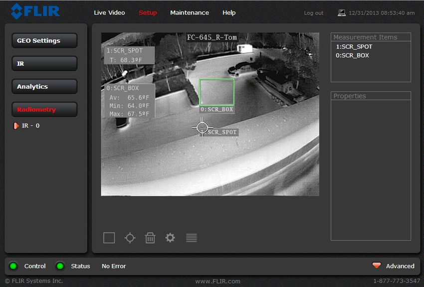
1   Camera Installation

    1.4.4      Camera Mounting with Concealed Cable Wall Mount
    The FC-Series camera can be secured to the optional Concealed Cable Wall Mount with four M5 x
    0.8 threaded fasteners to the bottom of the camera. Use Loctite 222 low strength threadlocker for the
    mount fasteners. Refer to Concealed Cable Mount Accessory, pg. 1-13 for additional information.

                      Figure 1-4: FC-Series Installed with Concealed Cable Wall Mount and
                                                 Pole Adapter kit

    1.4.5      Sunshield
    The camera includes a sunshield which should be used for any installation where the camera is
    exposed to direct sunlight or precipitation, If the camera is mounted with the top mounting holes, the
    sunshield is not used. Depending on the needs of the installation, the sunshield can be positioned in
    the neutral (middle) position, or slightly forward or rearward.To change the position of the sunshield,
    temporarily loosen the three 3 mm hex screws on top, slide the sunshield forward or backward, and
    re-tighten the screws.
            Sunshield mounting screws                          Cover mounting screws (x4)

                                        Figure 1-5: Sunshield Mounting

    427-0073-12-12 Version 110               June 2014                                      1-6
1 Camera Installation
1.5 Removing the Cover
Cover mounting
In order to access the electrical screws (x4)
connections and install the cables, it is
necessary to temporarily remove the top
cover of the camera housing. The top
cover of the camera is held in place with
four 3 mm hex screws. The screws are
accessible through slots in the sunshield,
so the sunshield does not need to be
removed from the top cover.
Use a 3 mm hex key to loosen the four
captive screws, exposing the connections
inside the camera enclosure. There is a
grounding wire connected inside the case
to the top cover, as shown. If it (or any of
the grounding wires) is temporarily
disconnected during the installation, it
must be reconnected to ensure proper Figure 1-6: Cover Removed (Sunshield attached)
grounding of the camera.
Caution!
When replacing the cover, ensure that the ground wire between the cover and the camera body is
completely inside the o-ring groove. If the wire is pinched between the cover and body the camera
is not sealed against water ingress and can be damaged.
Replace the cover and tighten the four 3 mm hex screws to 1.8 n-m (16.0 in-lbs).
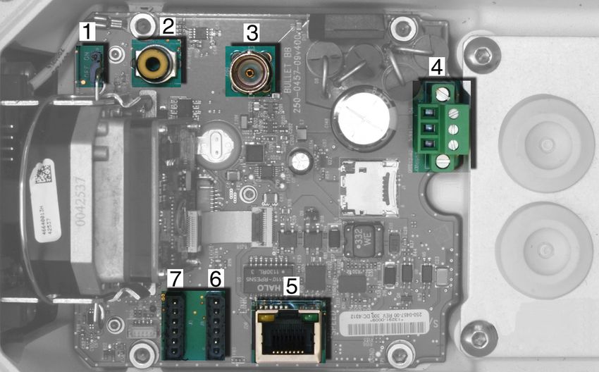
1.6 Camera Connections
Figure 1-7: Camera Connections
Refer to Table 1-1 for a description of these camera connections.
427-0073-12-12 Version 110 June 2014 1-71 Camera Installation
Table 1-1: FC-Series Camera Connections
Connection Purpose
1 3-pin Jumper Supplemental lens heater on/off
2 RCA Analog video test point
3 BNC Analog video
4 3-pin Terminal ac/dc power
5 Ethernet PoE+ power, communications, IP video stream
6 6-pin terminal J8 General purpose I/O
7 Accessory inputs Reserved for future use
1.6.1 Configuring the Lens Heater Jumper
The supplemental lens heater is intended to provide lens
de-icing in the rare combination of:
Pin 1
• A power interruption which disables the cam- Pin 2
era for an extended period, and Pin 3
• Freezing rain which fully covers the lens and
obstructs the image.
FLIR recommends that the supplemental lens heater be
enabled only when the installation environment is such that Figure 1-8: Lens Heater Jumper Setup
this combination of conditions is common.
The FC-Series camera is shipped from the factory with the supplemental lens heater OFF (jumper
pins 2 and 3). To enable the Supplemental Lens Heater, move the heater jumper to ON (jumper pins 1
and 2). Proper operation of the Supplemental Lens Heater requires that the camera be powered by 24
Vac, >16Vdc or POE+.
It is important to note that the supplemental lens heater is not required for operation in all cold
temperatures. The system operates to specification and produces highest quality images without the
Supplemental Lens Heater. Contact FLIR Technical Support for additional information (888-747-3547
inside the US).
427-0073-12-12 Version 110 June 2014 1-81 Camera Installation
1.6.2 Analog Video Connections
The primary analog video connection of the camera is a BNC connector. Alternatively, the camera
also provides an RCA analog video connector. Only one or the other connection should be used on a
permanent basis to ensure adequate video quality. The RCA connection allows the installer to
temporarily monitor the video output, without disconnecting the primary connection.
The video cable used should be rated as RG-59/U or better to ensure a quality video signal.
Note
Insert the cables through the cable glands on the enclosure before terminating and connecting them.
In general, terminated connectors will not fit through the cable gland. If a terminated cable is required,
it is possible to make a clean and singular cut in the gland seal to install the cable into the gland seal.
1.6.3 Connecting Power
The camera can be powered with a conventional ac or dc power
supply, rather than PoE+. Prior to making any connections,
ensure the power supply or circuit breaker is switched off.
Table 1-2: Power Connections
1 Chassis
2 Vac/dc -
3 Vac/dc + Figure 1-9: Power Connector
The power cable supplied by the installer must use wires that are sufficient size gauge for the supply
voltage and length of the cable run, to ensure adequate current carrying capacity (18 AWG
recommended for most installations). Always follow local building/safety codes.
Note
The terminal connector for power connections will accept 16 AWG to 24 AWG wire size.
The power connector plug may be removed for cable installation. After the plug is reattached to the
board, re-tighten the screw terminals.
Strip wires
Remove outer cover
Figure 1-10: Power Cable (3 conductor)
The camera itself does not have an on/off switch. Generally the FC-Series camera may be connected
to a circuit breaker and the circuit breaker will be used to apply or remove power to the camera. If
power is supplied to it, the camera will be powered on and operating.
427-0073-12-12 Version 110 June 2014 1-91 Camera Installation
1.6.4 Ethernet GPIO
Ethernet
Connect a shielded cat5e/6 Ethernet cable to the
RJ-45 jack. If using PoE+ to supply power to the
camera, connect the other end of the Ethernet to a
PoE+ switch or PoE+ injector. Otherwise connect
the Ethernet to a network switch.
J8 pin 1
1.6.5 GPIO Connections
Figure 1-11: GPIO and Ethernet Connectors
Input Signal—The camera can receive an
external input signal on accessory connector J8
pins 4 and 5 when these pins are connected by an
external switch closure. Pin 5 is connected to the
camera’s internal +5V power supply and must not
be directly connected to chassis ground. Pin 4 is 1. Insert wires 2. Snip wire
connected to the internal digital ground. through plug and close cage
While protection for static discharge has been
placed on these pins, care should be used in
making connections to the pins to avoid pin 1
connections to other voltages or power sources
outside the camera.
Output Signal—The camera can provide a
contact closure output signal on accessory
connector J8 pins 2 and 3 when an external
voltage is supplied to these pins. When open the
resistance between pins 2 and 3 is greater than Figure 1-12: GPIO Terminal Plug
100 K ohm. When closed the resistance between
pins 2 and 3 is less than 200 ohm. The maximum
recommended peak voltage between the pins is 6
volts. The maximum recommended current
allowed between the pins is 30 mA (0.03 A).
Table 1-3: GPIO Connections - J8
Pin Connection Notes
1 Chassis ground
2 GPIO Out When the camera sends an output signal, an
external voltage on one pin is applied to the
3 GPIO Out other pin.
4 Digital ground
When these pins are connected externally,
the camera reads this as an input signal.
5 +5V
6 Chassis ground
Note
The terminal plug supplied for GPIO connections, Phoenix Contact part number 1780493 uses
stranded, 26 AWG wire size (1 mm diameter including insulation) using spring-cage and pierce
contact technology.
427-0073-12-12 Version 110 June 2014 1-101 Camera Installation
1.6.6 Camera Grounding
Ensure the camera is properly grounded. Failure to
properly ground the camera can lead to permanent
damage to the camera. Typical to good grounding
practices, the camera chassis ground should be
connected to the lowest resistance path possible.
The camera has an external ground connection on
the outside back of the camera. FLIR requires a Ground
grounding strap anchored to the grounding lug and
connected to the nearest earth-grounding point.
If, during installation, any ground connections
inside the camera are disconnected, they should
be reconnected prior to closing the camera. Figure 1-13: Camera Ground Connection
1.7 Rear Access Cable Gland Sealing
Proper installation of cable sealing gland and use of appropriate elastomer inserts is critical to long
term reliability. Cables enter the rear of the camera mount enclosure through a liquid-tight
compression gland.
Leave the gland nut loosened until all cable installation has been completed, and ensure the
manufacturer’s recommended cable bend radius is observed within the enclosure. Do not forget to
tighten the cable gland seal nut to ensure a watertight seal and provide strain relief for cables.
Cable Gland Seal Inserts
The FC-Series camera comes with a single 3/4” NPT cable gland installed in the camera, with a four-
hole gland seal insert. The gland includes a sealing washer and is secured to the camera with a nut
on the inside of the enclosure. The gland insert has one hole for the RG-59/U analog video cable (the
larger hole) and three more for a power cable, Ethernet cable, and an accessory cable (not used at
this time).
Any of the holes which are not used for cables should be filled with one
of the hole plugs (supplied). Install the cables through the cable gland
so that the cables line up with the connections inside the camera.
Note
Insert the cables through the cable glands on the enclosure before terminating and connecting them.
In general, terminated connectors will not fit through the cable gland. If a terminated cable is required,
it is possible to make a clean and singular cut in the gland seal to install the cable into the gland seal.
To ensure a water tight seal when using the supplied rear cable gland, cable dimensions must be
within the minimum and maximum as described in Table 1-4.
If non-standard cable diameters are used, an appropriate cable gland and insert should be used to fit
the desired cable and to fit the hole in the enclosure. FLIR Systems, Inc. does not provide cable gland
inserts other than the insert supplied with the system.
If a replacement is used, inspect and install the gland fitting in the back cover with suitable leak seal or
sealant and tighten to ensure water tight fittings. To fit the 1.050 in. (26.7 mm) hole in the enclosure,
the thread size should be 3/4” NPT or M25. The gland should be installed with a sealing washer (for
example, Heyco PN 3261 or equivalent) between the gland and the external surface of the enclosure.
427-0073-12-12 Version 110 June 2014 1-111 Camera Installation
Video Cable
Accessory cable RG 59 coaxial
Ethernet Power Cable
3 Conductor
Figure 1-14: Cable Routing
Table 1-4: Rear Exit Cable Min/Max Dimensions
Cable Minimum Maximum Notes
Power (3 conductor), When using the concealed cable wall mount
4.5 mm 5.2 mm
Ethernet, Accessory (PN 4129742), cables can have a maximum diameter
[0.178 in] [0.205 in]
cables of 10 mm [0.394 in]
5.3 mm 6.4 mm
RG 59 Video cable
[0.209 in] [0.245 in]
427-0073-12-12 Version 110 June 2014 1-121 Camera Installation
1.8 Concealed Cable Mount Accessory
Do not route cables through the bottom of the camera unless the concealed cable wall mount (PN
4129742) is used. The wall mount is specifically designed for the camera and allows the opening to
seal properly. When using the concealed cable wall mount, cable dimensions must be within the
minimum and maximum as described in Table 1-5.
Table 1-5: Cable Min/Max Dimensions using Concealed Cable Wall Mount (PN 4129742)
Cable Minimum Maximum Notes
Power (3 conductor),
4.5 mm 10 mm When using the rear exit cable gland, the maximum
Ethernet, Accessory
[0.178 in] [0.394 in] diameter is 5.2 mm [0.205 in]
cables
5.3 mm 10 mm
RG 59 Video cable
[0.209 in] [0.394 in]
Proper installation of the seal plate and panel mount gland seals is critical to long term reliability.
Cables enter the bottom of the camera enclosure through the seal plate and panel mount glands. Be
sure to insert each cable through its panel mount gland on the seal plate before terminating them
(connectors will not fit through the gland). Ensure the manufacturer’s recommended cable bend
radius is not exceeded within the enclosure.
Prepare the Camera
Step 1 Use a 3 mm hex key to loosen the four captive screws and remove the top cover as
described above.
Step 2 Remove the rear cable gland and replace it with the cable gland plug. Use the gasket and
nut that were removed with the cable gland.
Step 3 Use a 3 mm hex key to
Seal plate Panel mount gland seals (x4)
loosen the four captive
screws and remove the
seal plate, o-ring, and
plug. Gland plug
installed
Plug
Figure 1-16: Removed Parts
Figure 1-15: Seal Plate Removed
427-0073-12-12 Version 110 June 2014 1-131 Camera Installation
Step 4 Install the wall mount (PN 4129742) to the wall
and pull the cable(s) through the mount. Cut a
small cross-slit in the black mount gasket and
push the cable(s) through the gasket. Pull the
cable(s) through the opening in the bottom of Mount Gasket
the camera. A single Ethernet cable is shown
in the images.
Step 5 Secure the camera to the mount using four M5
x 0.8 threaded fasteners to the bottom of the
camera. Use Loctite 222 low strength thread
locker for the mount fasteners. Figure 1-17: Camera Mount
Step 6 As needed, clean the o-ring and the o-ring
groove in the bottom of the camera using isotropy
alcohol and press the o-ring into its groove.
Step 7 For each cable, punch hole in the center of a gland
seal from the top using the 3 mm hex key. Insert the
cable from the bottom though the hole.
Step 8 Place the gland plate back into position and tighten
the four 3 mm captive screws using a torque value
of 1.8 n-m (16.0 in-lbs).
Step 9 Check the length of each cable to ensure an
appropriate bend radius and terminate the cable.
Step 10 Push the cable back through the gland seal so that
the seal is extended down not up, as shown in the Figure 1-18: Cable through Seal Plate
illustration below.
Wrong
Correct
Step 11 Connect the cables as indicated in Figure 1-7 on page 1-7. Ensure that any ground wire
that was removed during installation is reconnected. Replace the cover and tighten the four
3 mm hex screws to 1.8 n-m (16.0 in-lbs).
Caution!
When replacing the cover, make sure the ground wire between the cover and the camera body is
completely inside the o-ring groove. If the wire is pinched between the cover and the base, the
camera will not be sealed against water ingress and could be damaged.
Step 12 Using the hex key that is included with the concealed cable mount, loosen the ball joint on
the bottom of the mount, position the camera as required, and then re-tighten the ball joint.
427-0073-12-12 Version 110 June 2014 1-141 Camera Installation
1.9 Camera specifications
Camera Models FC-Series S, FC-Series R
Camera Platform Type Fixed
Composite Video NTSC or PAL
Thermal Camera
Array Format 324x256 (25 µm pixel pitch)
336x256, 640x480 (17 µm pixel pitch)
Detector Type Long-Life, Uncooled VOx Microbolometer
Effective Resolution 76,800
Field Of View (Focal Length) for FC-363 S = 63° × 50° (7.5 mm)
available FC-Series S camera lens FC-348 S = 48° × 39° (9 mm)
configurations. FC-334 S = 34° × 28° (13 mm)
FC-324 S = 24° × 19° (19 mm)
FC-313 S = 13° × 10° (35 mm)
FC-309 S = 9° × 8° (35 mm)
FC-690 S = 90° × 69° (7.5 mm)
FC-669 S = 69° × 56° (9 mm)
FC-645 S = 45° × 37° (13 mm)
FC-632 S = 32° × 26° (19 mm)
FC-618 S = 18° × 14° (35 mm)
Field Of View (Focal Length) for FC-334 R = 34° × 28° (13 mm)
available FC-Series R camera lens FC-324 R = 24° × 19° (19 mm)
configurations. FC-645 R = 45° × 37° (13 mm)
FC-632 R = 32° × 26° (19 mm)
Spectral Range 7.5 to 13.5 μm
Lens Athermalized, focus-free
General
Weight 4.8 lb (2.2 kg) with sun shield
Dimensions (L,W,H) 11.1" x 5.1" x 4.5" with sunshield,
(282 mm x 129 mm x 115 mm)
Input Voltage - dc 14 - 32 Vdc
Input Voltage - ac 18 - 27 Vac
Input Voltage - PoE+ IEEE 802.3af-2003 standard or higher power,
IEEE 802.3at-2009 standard
Power Consumption 5 W nominal at 24 Vdc
8 VA nominal at 24 Vac
Peak at 24 Vdc: 21 W with supplemental lens heater
Peak at 24 Vac: 29 VA with supplemental lens heater
Mounting Provisions Two 1/4-20” threaded holes on top and bottom,
1" spacing along center line front to back.
Four M5 threaded holes bottom,
40 mm x 62 mm (1.6 in x 2.4 in) spacing square.
Shipping weight 6.1 lbs (2.8 kg)
427-0073-12-12 Version 110 June 2014 1-151 Camera Installation
Shipping Dimensions 14.375”(L) x 7.375”(W) x 7”(H)
Environmental
IP rating (dust and water ingress) IP66 & IP67
Operating temperature range -50 °C to 70 °C (-58 °F to 158 °F) continuous
-40 °C to 70 °C (-40 °F to 158 °F) cold start
Storage Temperature range -55 °C to 85 °C (-67 °F to 185 °F)
Humidity 0-95% relative
Shock IEC 60068-2-27 10 g shock pulse
with a 11ms half-sine profile
Vibration MIL-STD-810F
Approvals FCC Part15, Subpart B, Class B,
EN 55022 Class B, EN 50130-4,
EN60950
427-0073-12-12 Version 110 June 2014 1-162 Basic Operation and Configuration
The camera has an Ethernet connection that allows streaming video over an IP network as well as
configuration and control of the camera1. It is possible to stream video and control the camera as it is
from the factory, without making any configuration changes. However in most cases the camera will have
at least some configuration changes to allow it to connect with other devices on the existing network.
Once the camera is connected to a network and powered on, the user can choose to use either the FLIR
Sensors Manager (FSM) software or a web browser2 to view the video and control the camera. The FSM
software is included with the camera. Refer to the FSM User Manual for details about using the software;
the manual is available from the Windows Start menu once the software is installed.
Getting the camera IP interface set up and working may require a level of familiarity with managing IP
networks that is new to many security professionals. Prior to configuring the IP interface and streaming
video parameters, make sure you know how to manage and configure the other equipment in the
network (for example, any PC or device that will connect to the camera, any router or firewall that will
carry the IP traffic, and so on). FLIR technical support can only provide limited support in this regard.
2.1 Basic Test and Configuration Steps
Assuming the existing network uses IP addresses that are unique and different than the default address
on the camera, configuring the camera for IP communications generally involves the following steps:
Step 1 Connect the Ethernet port to an IP network that is isolated from the existing camera network
(for example, a standalone switch)
Step 2 Connect a PC or laptop to the same network
Step 3 Temporarily set the IP address of the PC or laptop to be compatible with the factory network
address of the camera (for example, 192.168.250.1)
Step 4 Perform a bench test of the camera using a web browser or FSM, prior to making any
parameter changes (this step is optional but recommended)
Step 5 Configure the camera settings, such as IP address, camera date/time, security settings, and
video stream parameters, so the camera is compatible with the existing network equipment
Step 6 Save the configuration changes and restart the server
Step 7 Connect the camera to the existing network and test the camera
Step 8 Make a backup of the new configuration
2.2 Camera Bench Test
The camera offers both analog video and IP video, and since the camera can be powered by PoE+ or by
a conventional power supply, there are several ways to bench test the camera. It is recommended that
the installer test the camera using the same type of connections as in the final installation.
Even if using analog video and conventional power in the final installation, it is a good idea to test the IP
communications when performing the bench test. If any image adjustments are necessary, they can be
done using a web browser over the IP connection, and saved as power-on default settings.
1. For this chapter, it is assumed the camera will be connected to a network via Ethernet. For
installations that use only analog video output, it is not possible to make configuration
changes unless an Ethernet connection is also used.
2. The web interface is supported on Microsoft Internet Explorer version 9, as well as the latest
versions of Google Chrome and Mozilla Firefox.
427-0073-12-12 Version 110 June 2014 2-12 Basic Operation and Configuration
With the camera powered up, analog video can be tested at either the BNC connector or the RCA
connector. Connect the camera to a video monitor and confirm the live video is displayed on the
monitor.
If using a conventional power supply, connect the camera to a network switch with an Ethernet cable,
and connect a PC or laptop to the switch also. Use a web browser to access and test the camera as
described below, and if necessary make configuration changes prior to installation.
2.3 Web Browser Interface
The FC-Series camera is shipped with an IP address set to 192.168.250.116. Set the PC or laptop
network adapter to a compatible IP address, for example: 192.168.250.1 with a netmask of
255.255.255.0. If you are unsure how to set the IP address on the PC or laptop, refer to Setting the IP
address on a Windows PC, pg. 2-19.
Use a web browser to connect to the camera as described below, and confirm it is streaming video.
Once the bench test is complete, use the web browser to make configuration changes as needed (for
example, set the IP address to an address that is compatible with the existing network). It is also a
good idea to run the FSM software and confirm it is working with the camera as expected.
It is possible to log in to the camera using one of three User Names: user, expert, and admin.
By default, the passwords are: user, expert, and fliradmin, respectively. The user login can be used
to do the initial bench test of the camera. The expert login may be used to make configuration
changes such as setting the IP address. The login passwords should be changed to prevent
unauthorized log ins. To change the passwords, refer to Basic Camera Configuration, pg. 2-6.
Note
Two web sessions can be active at once. An inactive session will be stopped after 20 minutes.
Log in to the Camera Web Page
Step 1 Open a web browser and enter: http:\\192.168.250.116. The login screen with a picture of
the camera will appear.
Step 2 Enter user for the User Name and user for the Password, and click Log in.
Figure 2-1: Camera Web Page Login Screen
427-0073-12-12 Version 110 June 2014 2-22 Basic Operation and Configuration
2.3.1 Live Video Page
The Live Video page will be displayed, with a live image from the camera on the left part of the
screen. Next to the FLIR logo along the top of the screen are some menu choices, including Live
Video (the red text indicates it is selected), Help, and Log out. The expert and admin logins will see
additional menu choices.
Mouse-over
Temperature Alarm Snapshot Toggle Time
Temperature
Reading
Video
Analytics
Area
Figure 2-2: Live Video Web Page
If the live video is not displayed, refer to Troubleshooting Tips, pg. 2-14. In the lower right of the web
page there is a frame rate selector. This selector allows the user to change the rate at which the
frames are displayed in the browser. This rate controls the user’s own web browser only, and does not
affect the video streams to other users or to an NVR.
Help
At the top of the page, the Help menu displays software version information. This page has
information about the camera including hardware and software revision numbers, part numbers, and
serial numbers. If it is necessary to contact FLIR Technical Support for assistance, it will be helpful to
have the information from this page (such as Software Version) on hand.
Log out
Use this button to disconnect from the camera and stop the display of the video stream. If a web
session is inactive for 20 minutes, it will be stopped and you will have to log in again.
Toggle Camera/PC time
Use this button to view either your PC time or the camera time.
427-0073-12-12 Version 110 June 2014 2-32 Basic Operation and Configuration
Temperature—FC-Series R camera only
The FC-Series R camera can provide temperature measurements, the precision of which depend on
many factors, including the ambient temperature, the distance to the object, and emissivity, an
indication of how well a particular material radiates energy. By default, box and spot measurement
areas are setup near the center of the video image to alarm near 90 °F (body temperature). Refer to
Temperature Monitoring Setup (FC-Series R camera only), pg. 3-7.
Camera Control and Status Mouse-over
Zoom
In the lower left of the screen are two indicator lights: Control and Status.
Initially the Control light is off, as in the image above, indicating the user is not
able to control the camera. When multiple users are connected to a camera,
only one user at a time can issue commands to the camera. If another user
has control of the camera, the Control light is yellow. A user is able to request
control of the camera by clicking on the yellow or black light, or simply by
sending a command to the camera. The Status light may turn off temporarily
while waiting for the response from the camera. Be patient, there may be a slight delay between each
command while the browser waits for a response from the camera.
In addition, when the cursor is moved over the video, there are mouse-over zoom buttons and a
mouse-over snapshot button. The zoom buttons appear in the lower left of the screen; the snapshot
button appears in the upper right of the screen. After clicking the snapshot button, the video image is
saved as a .jpg file and the browser will provide prompts depending on which browser is being used.
Web Control Panel
The control buttons on the right side of the page provide a way to control
the camera in a limited number of ways. When the mouse cursor is
positioned over a button, a tool tip is displayed.
This same web interface is used with various FLIR thermal cameras—
some are fixed, such as the FC-Series cameras, and some are pan/tilt
cameras. As a result, different buttons in the control panel will appear for
different FLIR cameras.
The following buttons appear for the FC-Series cameras:
Digital Zoom
These buttons zoom the displayed video. The zoom state (and other camera settings)
can be saved in the IR Setup page (refer to Save Settings, pg. 3-3). This will allow the
camera to retain the desired zoom state (field of view) after the power is cycled.
Toggle Polarity
This button changes the polarity of the assigned colors to the different temperatures in a
scene. In the black and white palette for example, hot objects are displayed as white and
cold objects as black, or vice versa.
Toggle Palette
This button causes the camera to cycle through six different look up table (LUT) color
palettes. Depending on the subjects viewed, one color palette may be preferable to the
others. The Toggle Polarity button allows access to six more palettes (refer to Misc. (Lookup
Table), pg. 3-3).
427-0073-12-12 Version 110 June 2014 2-42 Basic Operation and Configuration
Perform IR NUC Calibration
This button causes the camera to perform a Non-Uniformity Correction operation (refer to
Image freezes momentarily, pg. 2-14).
Toggle Automatic Gain Control (AGC)
This button causes the camera to cycle through 5 different AGC options that use a
combination of settings to produce different configurations that could improve the video
image for a given set of conditions.
Toggle Scene Preset
This button causes the camera to cycle through 5 different image settings. The Scene
Presets cause the image brightness and contrast to adjust. Depending on the time of day,
weather, and other conditions, one Scene Preset may be preferable to the others.
Function
The FC-Series cameras have additional features or functions which can be accessed using
an extra numeric function keypad. It is possible to create customized camera functions
through a “macro” interface which can be programmed through XML commands. Contact
FLIR Technical Support for information about the Nexus XML-Based Control Interfaces.
When the Function button is selected, the keypad changes to a numeric
keypad providing programmed functions (1 - 9). Select the back arrow to
return to the main keypad. Some specific cameras can have additional
functions (10 - 18). The forward arrow will access these.
Refer to the following table for definitions of the nine functions available to
FC-Series cameras. The video enhancing options in some cases may
improve the video image, at least temporarily. Over time or as the
environment changes, the scene could change and the resulting image
may no longer be optimal.
FN Function Description
1 Enable EE Edge enhancement (EE) is an image processing technique that enhances details by
emphasizing lines and edges. It may be possible to see fine details more easily in some
2 Disable EE scenes, but it could also make the image somewhat more grainy or pixilated.
3 SAL-DRE Global
4 SAL-DRE Local
5 SAL-DRE Off The Scene Adaptive Local Dynamic Range Enhancement (SAL-DRE) algorithm may
improve the dynamic range of some scenes by adaptive tone mapping such that the
6 SAL-DRE Low contents in both the dark and bright regions are visible.
7 SAL-DRE Medium
8 SAL-DRE High
An email will be sent to the default email list as configured in the Notification Lists using
9 Send Test Email the SMTP server defined in Msg Systems (refer to Msg Systems, pg. 2-9). The email will
have simply “Test” in the Subject and “FC-Series Test Email” in the message body.
427-0073-12-12 Version 110 June 2014 2-52 Basic Operation and Configuration
2.4 Basic Camera Configuration
The following procedures describe how to do the most common bench test camera configuration
steps, such as setting the camera IP address and hostname and changing the user password. To
make these changes, it is necessary to login using the expert user account. Additional setup and
configuration options required after the camera has been installed in its final location are described
after the basic steps are given, refer to Advanced Configuration, pg. 3-1.
2.4.1 Setup Menu
The Setup menu is used for GEO Settings (Latitude and Longitude, for example), thermal (IR)
camera settings, defining Video Analytics motion detection zones, and setting Radiometry
temperature measurement areas (FC-Series R only), refer to Setup Menu, pg. 3-1.
Adjustments to the IR settings should only be made by someone who has expertise with thermal
cameras and a thorough understanding of how the various settings affect the image. In most
installations, the only camera settings needed are available from the Web Control panel on the Live
Video page (Scene Presets, Polarity, Palettes, AGC, and zoom). Haphazard changes can lead to
image problems including a complete loss of video. Additional information is provided in Thermal
Image Setup, pg. 3-2.
When a user logs in as admin, a complete Maintenance menu is available (refer to Global Settings,
pg. 3-10). The Maintenance menu also provides access to other configuration options. For more
information on setting or changing other camera parameters refer to the Nexus IP Camera
Configuration Guide (FLIR Doc #427-0030-00-28).
2.4.2 Server Menu
When a user logs in as expert, the Maintenance Server
menus are available. When the Server menu is selected, the
LAN Settings page appears.
In order to make some configuration changes through the
Maintenance menu, it is necessary to save the changes, then
stop and restart the server to make the changes take effect3.
The basic camera configuration steps are accessed through
the Maintenance Server menu, using the menus on the left
side of the page. The LAN Settings, Services, and Security
Options selections are described below. The expert login has
access to these Server pages, but will only see the security
settings for the user login.
3. When making configuration changes using the Setup page, most of the changes take
effect immediately, and it is not necessary to start and stop the server. However it is neces-
sary to save the changes (with the Save Settings button at the bottom of the page) if it is
desirable to use the new settings as a default when the camera is powered on.
427-0073-12-12 Version 110 June 2014 2-62 Basic Operation and Configuration
LAN Settings: The LAN Settings page can be used to set the hostname, default gateway, and IP
address for the camera. A more descriptive Friendly Name (used by FSM) can be set from the
Product Info page with the admin login. The default IP Address mode is static; the mode can also be
set to DHCP.
When the LAN settings are changed and the Save
button is clicked, a pop-up message will appear to
indicate the network interface must be restarted.
Once the IP address of the camera is changed, the PC
may no longer be on the same network and therefore
may not be able to access the camera until the IP
address on the PC is changed also. For that reason,
you may wish to change the IP address after making
other configuration changes.
To reset the IP address to the factory default using a
loopback connector, refer to Restoring the Factory
Settings, pg. 3-26.
Note
The IP address is temporarily displayed on the analog video after the camera finishes its boot cycle.
If you are unsure of the camera IP address, it is useful to reboot the camera and watch for the IP
Address information after the camera boots up (usually about 90 seconds after power is applied).
427-0073-12-12 Version 110 June 2014 2-72 Basic Operation and Configuration
Services Menu
Date and Time: The Date and Time settings page is used to configure the date and time settings.
The date, time, and time zone can be obtained from an NTP server, or can be entered manually. If
NTP mode is selected, the NTP server information can be entered. The Nexus server must be
stopped before changes can be saved. After saving changes, it is necessary to restart the server to
make them effective.
Toggle Server (Stop/Start)
If the Custom mode is selected, a pop-up window allows the information to be entered manually.
Set the date and time parameters, then select the Save button at the bottom of the page.
427-0073-12-12 Version 110 June 2014 2-82 Basic Operation and Configuration
Msg Systems: Use the Msg Systems page to setup a connection to a mail server to send outgoing
email notifications.
Ensure Gateway and DNS servers are supplied. Refer to LAN Settings, pg. 2-7. Configure the Msg
Systems page with mail server information then click Save.
Notification Lists: Use this page to setup multiple email addresses and other notifications that can
be sent as a result of alarms being processed by the Alarm Manager.
The email address entered into the Default Notification List will be used to send a test email (FN 9)
from the Live Video page.
427-0073-12-12 Version 110 June 2014 2-9You can also read