DUO XXL - Operating instruction - Coin and chip card system Remote maintenance via internet - Holtkamp Electronics GmbH
←
→
Page content transcription
If your browser does not render page correctly, please read the page content below
DUO XXL
  Coin and chip card system
Remote maintenance via internet

    Operating instruction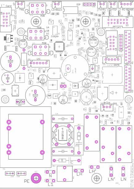
Holtkamp Electronics DUO XXL                         techn.stand 01.2018                          4022_01.2018/V05.2020

Important: For safe and proper use, read the instructions for use and further product-related documents carefully and keep
it for later use!

For errors, technical errors, printing errors and incompleteness, we assume no liability.

                                                              -2-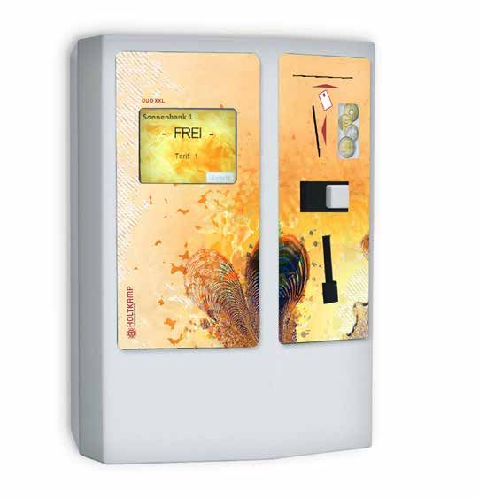
Holtkamp Electronics DUO XXL                                                   techn.stand 01.2018                                                4022_01.2018/V05.2020

                                                                                                                    S ü d s t r a ß e 4 0 / D- 4 9 0 8 4 O s n a b r ü c k
                                                                                                                    info@holtkamp.de / www.holtkamp.de

                       EU-Konformitätserklärung / European Union conformity explanation
    Für das nachfolgend bezeichnete Erzeugnis / For the following designated product

                                                           Zeitsteuerung vom Typ / Time control type

                                                                                 DUO XXL
                                mit Notaus-Timer (110%)-Funktion / with emergency stop timer (110%) function

    wird hiermit bestätigt, dass die Bauart, in der von uns in Verkehr gebrachten Ausführung, den unten genannten Normen
    entspricht.
    It is hereby confirmed, that the construction in that execution brought by us in traffic corresponds to the standards specified
    down.

    Diese Erklärung gilt für alle Geräte, die nach den beiliegenden technischen Unterlagen, welche Bestandteile dieser Erklärung
    sind, hergestellt werden.
    This explanation applies to all devices, after the enclosed technical documents, which are components of this explanation,
    are manufactured.

    Einschlägige EG-Richtlinien / Relevant EC guidelines
    RoHS-Richtlinie 2011/65/EU / RoHS Directive 2011/65 / EU

    1. 2006/95/EG (Niederspannungsrichtlinie)
       2006/95/EG (low-voltage guideline)
       geändert durch
       changed through
       2014/35/EU

    2. 2004/108/EG (EMV-Richtlinie)
       2004/108/EG (EMV guideline)
       geändert durch
       changed through
       2014/30/EU

    Angewendete harmonisierte Normen:
    Applied one harmonized standards:

         EN 60335-1 von 01/12 (Sicherheit)
         EN 60335-1 from 01/12 (security)
         EN 55022 von 12/11 (Emissionen)
         EN 55022 from 12/11 (emissions)
         EN 61000-3, Teil 2 + 3 von (03/2015 und 03/2014) (Emissionen)
         EN 61000-3, part 2 + 3 from (03/2015 and 03/2014) (emissions)
         EN 61000-6, Teil 1 + 2 von (10/2007 und 03/2006) (Immunität)
         EN 61000-6, part 1 + 2 from (10/2007 and 03/2006) (immunity)

    Diese Erklärung ist bindend für den Hersteller
    This declaration is binding on the manufacturer

    Manfred Holtkamp Elektronik GmbH
    Südstraße 40 in 49084 Osnabrück
    abgegeben durch:
    Signature:
    M. Hashemizadeh (EMV-Beauftragter)

    ..........................................
    Osnabrück, den 05.09.2018

    Telefon: +49 541 97120-0, Fax: +49 541 97120-40
    Geschäftsführung: Magnus Michael, Uwe Staudinger; Sitz der Gesellschaft: Osnabrück, AG Osnabrück HRB 213567
    Banken: Deutsche Bank Osnabrück, IBAN: DE28 2657 0090 0039 5251 00; SWIFT/BIC: DEUTDE3B265
    Die Lieferung erfolgt zu unseren Allgemeinen Geschäftsbedingungen mit Stand Juni 2011 nach ZVEI unter Einbeziehung der Softwareklausel
    zur Überlassung von Standard-Software als Teil von Lieferungen mit Stand April 2012 nach ZVEI.
    Zusätzlich gelten unsere Vertragsbedingungen „Hardware/Schaltplan/Layout“ und „Auftragsfertigung“.
    Es gelten unsere Einkaufsbedingungen mit Stand Januar 2018.

                                                                                         -3-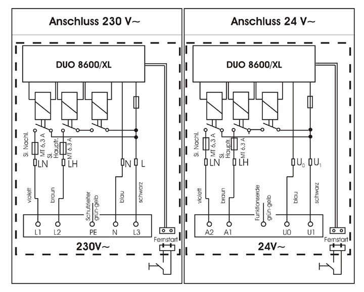
Holtkamp Electronics DUO XXL                                                        techn.stand 01.2018                                                        4022_01.2018/V05.2020

                                                                                          Content
1  Legal information.......................................................................................................................................................................... 6
2  Warranty		 ................................................................................................................................................................................. 6
3  Safety notices .............................................................................................................................................................................. 6
4  Device specific data..................................................................................................................................................................... 6
5  General data ................................................................................................................................................................................. 7
6  Illustrations ................................................................................................................................................................................. 7
   6.1		 Illustration of the device....................................................................................................................................................... 7
   6.2		 Illustration of electronic / Position of the connectors and switches on the PCB.................................................................. 8
7 Installation ................................................................................................................................................................................. 9
   7.1		Installation notes................................................................................................................................................................. 9
   7.2     Mounting instruction............................................................................................................................................................ 9
   7.3     Electrical connection......................................................................................................................................................... 10
8 Deployment options................................................................................................................................................................... 12
9 The chip card types.................................................................................................................................................................... 12
10 Special features.......................................................................................................................................................................... 12
11 Equipment feature...................................................................................................................................................................... 13
   11.1 DIP switches...................................................................................................................................................................... 13
   11.2 Jumper.............................................................................................................................................................................. 13
12     Menu settings........................................................................................................................................................................ 14
   12.1 Menu call........................................................................................................................................................................... 14
		 12.1.1 Menu call via DIP-switch.............................................................................................................................................. 14
		 12.1.2 Menu call via Holtkamp service card .......................................................................................................................... 14
		 12.1.3 Menu call via password entry via touch screen (jumper 1 is plugged in) .................................................................... 14
		 12.1.4 Sequence of the password entry ............................................................................................................................... 15
   12.2 General information menu control..................................................................................................................................... 15
		 12.2.1 Copy and paste............................................................................................................................................................ 16
		 12.2.2 Turn pages, leave menu.............................................................................................................................................. 17
13 Statistic menu............................................................................................................................................................................ 17
   13.1 Sub menu Statistic............................................................................................................................................................ 17
   13.2 Statistic menu daily counter „Sale“.................................................................................................................................... 18
   13.3 Statistic menu daily counter „Card revaluation“................................................................................................................. 19
   13.4 Statistic menu daily counter „different” ............................................................................................................................. 19
   13.5 Statistic menu daily counter „Sales“.................................................................................................................................. 20
   13.6 Statistic menu total counter „Card revaluation“................................................................................................................. 21
   13.7 Statisic menu total counter „different“ ............................................................................................................................... 21
   13.8 Statistic menu „Service counter“....................................................................................................................................... 21
14 Information menu....................................................................................................................................................................... 22
   14.1 Information menu XXL....................................................................................................................................................... 23
   14.2 Information menu chip card............................................................................................................................................... 23
   14.4 Information menu internal modules................................................................................................................................... 24
   14.4 Information menu external modules.................................................................................................................................. 24
15 Menu Times and Prices ............................................................................................................................................................. 25
   15.1 Sub menu Times and Price menu .................................................................................................................................... 25
		 15.1.1 Times and Prices „Times“............................................................................................................................................ 25
   15.2 Menu points „Times and Prices“........................................................................................................................................ 26
		 15.2.1 Times and Prices „Prices“............................................................................................................................................ 27
16 Menu Clock and Shifting times................................................................................................................................................. 28
   16.1 Sub menu Clock and shifting times................................................................................................................................... 28
		 16.1.1 Menu Clock and shifting time „Time and Date“............................................................................................................ 29
		 16.1.2 Menu Clock and Shifting times „Shifting times“........................................................................................................... 29
17 Menu chip card editing and revalue.......................................................................................................................................... 31
   17.1 General menu points for service chip card type 73 .......................................................................................................... 31
   17.2 Chip card editing via service chip card type 73................................................................................................................. 31
   17.3 Chip card revaluating via service card type 73 ................................................................................................................. 31
   17.4 Chip card revalue via cash insertion................................................................................................................................. 32

                                                                                                  -4-
Holtkamp Electronics DUO XXL                                                       techn.stand 01.2018                                                       4022_01.2018/V05.2020

18 Configuration Menu.................................................................................................................................................................... 33
   18.1 Sub menu "Configuration" ................................................................................................................................................ 33
      18.1.1 Configuration „Language + Currency“......................................................................................................................... 33
      18.1.2 Configuration „Display + Sound” ................................................................................................................................. 34
      18.1.3 Configuration „Div. operating parameters“................................................................................................................... 36
      18.1.4 Configuration „Payment“.............................................................................................................................................. 40
      18.1.5 Configuration „Tanning management“......................................................................................................................... 42
      18.1.6 Configuration „Object data“.......................................................................................................................................... 45
      18.1.7 Configuration „Counter statistic“.................................................................................................................................. 47
      18.1.8 Configuration „Service intervals“.................................................................................................................................. 48
      18.1.9 Configuration „Coin validator“...................................................................................................................................... 49
      18.1.10 Configuration „Data Interfaces“.................................................................................................................................. 51
19 Operating of the XXL.................................................................................................................................................................. 52
   19.1 Time purchase................................................................................................................................................................... 52
		 19.1.1 Time purchase via chip card ....................................................................................................................................... 52
		 19.1.2 Time purchase by coin insert ...................................................................................................................................... 53
		 19.1.3 Buy more time.............................................................................................................................................................. 54
		19.1.4 Time sequence............................................................................................................................................................ 55
		19.1.5 Multi-Timer................................................................................................................................................................... 56
   19.2 Card editing and revaluating............................................................................................................................................. 57
		 19.2.1 Card editing with service chip card type 73................................................................................................................. 57
		 19.2.2 Chip card revaluating with service chip card type Typ 73............................................................................................ 58
		 19.2.3 Chip card revaluating via coin insertion....................................................................................................................... 59
   19.3 Check device version, date and time ............................................................................................................................... 59
21 FAQ – Frequently asked questions........................................................................................................................................... 60
20 Reset to factory settings............................................................................................................................................................ 60
22 Error functions ........................................................................................................................................................................... 61
   22.1 Code of error messages.................................................................................................................................................... 62
Index				............................................................................................................................................................................... 66

                                                                                             -5-
Holtkamp Electronics DUO XXL techn.stand 01.2018 4022_01.2018/V05.2020
1 Legal information
2 Warranty
All rights reserved. No part of this manual may not be repro-
duced or copied in any form without permission of Holtkamp On the function of the device is granted for a period of 12 months.
Elektronik GmbH. The rights for contained software in control The warranty is limited solely to technical defects of the unit, it
and memory blocks are exclusively from the manufacturer. can´t be accepted further claims. Further apply our general
The reading and copying of the program content is strictly pro- terms and conditions, stand of June 2011, for products and
hibited. The Holtkamp Elektronik GmbH is not liable to the services of the electrical industry (ZVEI) - also see website: www.
purchaser of this product or third parties for damages, los- holtkamp.de.
ses, costs or expenses caused by the buyer or any third party Any liability extinguished by the manipulation of the device.
due to accident, misuse or unauthorized alterations, repairs or
improvements.
The Holtkamp Elektronik GmbH shall remain liable for any loss,
costs, disruptions or consequential damages that result from the
use of the control.
The technical data are up to date. Misprints, errors and modi-
fications excepted. Older manuals are no longer valid with the
publication of this manual.
3 Safety notices
The coin/chip card boxes are built according to the prior art and Perform no changes and/or modifications to the coin/chip card
the recognized safety rules. box without approval of the manufacturer! Spare parts must meet
Nevertheless, its use threats to life and limb of the user or third the requirements specified by the manufacturer. This is guaran-
parties, or cause damage to the device or other equipment teed only for original spare parts. Do observe the in the user
during use. Use the device only in perfect condition, and in- manual specified or prescribed deadlines for recurring main-
tended, safety and the risk of danger, in compliance with the tenance intervals! Do provide for the safe and environmen-
instruction manual! Do immediately eliminate particular dis- tally
orders, which may affect safety! Always keep the operating friendly disposal of plastic parts and electronic replacement
instructions directly to the coin box! Note, in addition to the parts! The manufacturer is not liable for damage caused by
user guide, the generally applicable legal and other man- improper use. The user bears the risk. Intended use also inclu-
datory des compliance with the operating instructions and compliance
regulations relevant to accident prevention and environmental with the inspection and maintenance conditions.
protection!
4 Device specific data
After switching on the electricity on the display appears for
approx. 2 seconds: Holtkamp XXL X.x, below in the second
row: T-Timer. This is information about the used software version
(XX.x) as well as the operating type of the DUO (T-Timer).
These details are subject of the advanced development of the
DUO and your order. For further questions and orders these de-
tails will constitute an advantage. Please note all the abbrevia-
tions appearing on the display, definitely, for any other technical
requests, in the following list.
ATTENTION:
The installation must be performed by authorized
personnel! Therefore, make sure that the installati-
on is carried out by an electronics specialist! Sin-
ce this is a stationary device with main-side fixed
connection, a circuit breaker must be installed on
the installation side!
-6-
Holtkamp Electronics DUO XXL                             techn.stand 01.2018                                4022_01.2018/V05.2020

5       General data

 Casing material                                                  galvanised steel plate 2mm

 Casing color                                                     powder coated white RAL 9016

 Dimensions                                                       h 300 mm x w 218 mm x d 141 mm

 Power supply                                                     230 V or 24 V, 50 / 60 Hz

 Switched power                                                   6,3 A by cos phi = 1

 Power absorption                                                 10 VA

 Cable entrance                                                   von hinten (3 Bohrungen)

 Temperature range                                                0°C - 50° C

 Protection class                                                 I bei 230V~ bzw. III bei 24V~

 Protection type                                                  IP 20

 Fuse circuit board SI1                                           100mA T

 Fuse main relay SI 2                                             6,3A MT

 Fuse run-out relay SI 3                                          6,3A MT

 Attention: Fuses may only be replaced with the same value!

We reserve the right to technical changes in the production and
technical developments

6       Illustrations

6.1     Illustration of the device

        18           14                       1      2

13
14                                                                     3
                                                                       4        1        3,5“ Touch screen
16
                                                                                2        Casing
                                                                                3        Card slot
13                                                                     5        4        Coin slot
                                                                                5        Coin reject button
15                                                                              6        Coin return
                                                                       6        7        Coin removel
14                                                                              8        Lock
                                                                                9        Coin bag
                                                                                10       Fuse plate
14
                                                                                11       Holes for 13
13                                                                              12       Securing bolts
12                                                                              13       Securing for the casing
11                                                                              14       Cable entrances
                                                                                15       Earth terminals
10                                                                     7        16       SB frame
                                                                                17       Securing holes
    9
                                                                                18       Rear wall
                                                                       8

                                                               -7-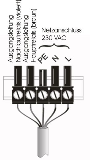
Holtkamp Electronics DUO XXL                            techn.stand 01.2018                                  4022_01.2018/V05.2020

6.2    Illustration of electronic / Position of the connectors and switches on the PCB

All required connections and switches are located on the power circuit board:

                                  1         2           3          4                   5    6        7

                19
                                                                                                             8
                18
                 2
                                                                                                             9

                 2

                                                                                                            10

                                                                                                            11

                                                                                                            12

                                                                                                  17

                                                17          16           15       14       14   13

1      Card ejection magnet                                             11    SD card
2      MDB                                                              12    Bypass switch
3      Erase button / blockade                                          13    Overrun time relay exit
4      DIP switches                                                     14    2 connections for main and overrun time relay, if
5      Remote start/cleaning button                                           potential-free
6      Time stop/Door opener                                            15    Main relay exit
7      RS485 to the PC                                                  16    Fine assurance 100 mAT (if 230V)
8      Expansion board                                                  17    Power connections
9      Coin validator (Parallel-EMP)                                    18    Jumper
10     Skin measurment head                                             19    Chip card

Connections and functions in brackets are optional. See further
descriptions of the individual components and connections in the
following chapters!

Changes and errors excepted!

                                                                       -8-
Holtkamp Electronics DUO XXL techn.stand 01.2018 4022_01.2018/V05.2020
7 Installation
7.1 Installation notes
Through high quality micro-electronics is the device able to ● This device may only be mounted on a suitable surface.
reach a high standard of reliability in the daily use. Only
if the installation has been professionally carried out can the ● The device must be sufficiently secured, take into consi-
device be guaranteed. Please consider during the installation... deration the weight of the inserted coins. There are 6 holes
in the back of the casing to accomplish the mounting pro-
● Only authorized and qualified electricians carry out the cess. Screws and dowels are included by delivery.
installation complying with the valid VDE–regulations.
● The device must be mounted horizontally and vertically to
● By the timers with 230 V~ supply voltage is definitely guarantee a flawless function of the coin receiver. That me-
the protection cable required, by the timers 24 V~ (safety ans the angle of the device can only be maximum 2 º, slo-
extra-low voltage) protecting grounding is needed as func- ping forward or backward, as well as to the right or the
tion earth left.
● That the floor covering is anti-static and conductor capable, ● The input cables are fixed by three drilled holes in the rear
to ensure a minimum of static change and so reducing the wall. The device is corresponding to protection type IP 20
danger to the electronics. an may only be used in dry rooms. Choose a cable cross
section of the feed line adequate big. Attend thereby the
● A malfunction or breakdown of the device can be caused connected electrical load. Attend to the VDE guidelines.
by the switching sparks of the relay contacts. To reduce
these sparks appropriate suppression combinations
must be included parallel to the protection contacts.
RC combinations for sparks reducing are only affective
by direct parallel switching of the relay contacts.
● That the screened control and data cable are laid sepa-
rately from mains cables. The screening of the DUO XXL
electronic must be one - side and laid on PE.
● That the feed line are used, which is from a big cross section
to supply both the DUO XXL and the attached electric
consumer. It should be used an cross section from
1,5mm² at the minimum.
7.2 Mounting instruction
Switch off the power supply by switching over the Drill the holes and insert suitable dowels. Through the holes "13”
corresponding disconnector or switch off the fuse or (see image of the device) on the rear wall connect up the elec-
even by tripping the RCCB. tricity. With the appropriate screws secure the casing tightly.
Now reinstall the electrical connections. Place the casing on
● Unlock and remove the coin box. the fixing bolts “12”. As a counter measure place the fuse plate,
through the opening of the removed coin box, on the fixing bolts
● Loosen the two screws of the fuse plate, remove the fuse
“11” and tighten with the supplied screws
plate and raise the casing so that it is possible to pull out
the electrical connectors. Pull out the electrical plug connec-
tions and remove the casing completely.
● The wall plate horizontal and vertically align with the help
of a level.
The tilt angle can only be 2° now mark the drilled
holes.
-9-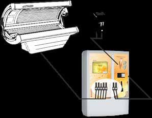
Holtkamp Electronics DUO XXL techn.stand 01.2018 4022_01.2018/V05.2020
7.3 Electrical connection
The electrical connection can only be carried out
by authorized and qualified personnel!
The electrical connection has to be carried out by the local
VDE regulations. With a permanent connection, an all pole
mains separator with at least 3 mm contact gap must be used.
Before starting the electric the corresponding circuit must be
disconnected. Shut down the mains input by activating the
separator switch, remove the fuse or release the main safety
fuse. Mains and low voltage cable must be spaced apart. Low
voltage cables should be generally spaced as screened cables.
Outside of office hours, the XXL should be swit-
ched off to preserve the image quality of the dis-
play for as long as possible (minimize age-related Control cable and remote start connection have
reduction of contrast and brightness)! to be kept away from each other.
Connection 230 V~ Connection 24 V~
DUO XXL DUO XXL
Fuse over run
Fuse over run
main r.
main r.
Fuse
Fuse
protective conductor
protective conductor
green-yellow
green-yellow
brown
brown
violet
black
violet
black
blue
blue
Remote Remote
start start
- 10 -Holtkamp Electronics DUO XXL techn.stand 01.2018 4022_01.2018/V05.2020
Connection 230V Remote start (potential free)
Overrun relay (violet)
main relay (brown)
Main relay
230 VAC
Outlet wire
Outlet wire
Lead shielding
to a PE jam!
After complete installation of XXL you can take it into operation Please make sure that your adjusted main time is appropriated
by switching on the circuit. As soon as the circuit is activated, to the tanning bed. Do not choose the main time too long, becau-
appears in the display an information about the operation mode se of the danger of the sun bed customer. Use the adjustment
of you DUO XXL and about the used software. The DUO XXL setting, to limit the maximum time and therefore limiting the ma-
is now ready for operation and can now be programmed as you ximum account of buyable main time to reduce to a minimum the
like. To ensure, that the programming has been correct, you danger to the customer.
should make a detailed test run. After this test run all counters
should be deleted to receive a correct account.
For DUO XXL version „Sun“ applies:
March 2003 110% disconnection
After norm EN 60335-2-27/A11 (VDE 0700 part 27)
Beginning with 01 may 2003 all our XL devices
are equipped with the disconnection recommen-
ded by the upper mentioned directions.
EN60335-2-27
The PCB of DUO is provided with a 110%-disconnection. It me-
ans, that an emergency stop timer is controlled by a third relay
on the PCB. It guarantees the switching off of the sun bed, if the
main relay is not switching off once, after the expired time.
- 11 -Holtkamp Electronics DUO XXL techn.stand 01.2018 4022_01.2018/V05.2020
8 Deployment options The DUO XXL are available in 2 different versions for 2 applica-
tions:
The XXL device is used for billing of timed objects (tanning beds, 1. DUO XXL Single-Timer (Sun):
washingmachines, Whirlpools, Tennis court lighting a.o.). Espe- e. g. connection of one tanning bed per device
cially for the control of tanning beds it has software-supported 2. DUO XXL Multi-Timer (Sun):
options for UV dosage and a hardware over 110% safety shut- e. g. connection up to 8 tanning beds per device
down, to prevent a too long tanning time in the case of a techni- 3. DUO XXL Single-Timer (Washing):
cal defect. e. g. connection of one washing machine per device
4. DUO XXL Multi-Timer (Washing):
e. g. connection up to 8 washing machines per device
9 The chip card types
For issue to the customer as a means of payment and for pro-
gramming the standard and special functions there are various
chip card types. Below you can see a tabular list and explanation
of the existing chip card types.
Chip card type Function
PIN-Card
P11 re-valuation chip card for the customer
P14 re-valuation test chip card for the service technician (second operating)
P15 re-valuation test chip card for the service technician (second operating)
P33 Chip card for querying the statistics and delete daily counters (for owner/personnel)
P43 Chip card for querying and delete the statistic exclusive for the operator (only for owner)
P53 menu programming chip card exclusive for the operator (only for owner)
P63 clock programming chip card exclusive for the operator (only for owner)
P73 Chip card for the activation of the re-valuation function (for owner/personnel)
P83 Configuration card from software 8.7 (select the customer configuration menus/only for owner)
10 Special features
● daytime switching of prices and peak time via integrated ● Fulfilling of the DIN EN 60335-1 standard, chapter “R1 pro
clock grammable electric circuit, using the software”:
o Hardware- and Software-Watchdogs
● Fullfilling of the EU-standard 60335/2/27 (radiation protec- o Oscillator-timing monitoring (permanent)
tion) while running with tanning beds: o RAM- and ROM- verification (when switching and cycli-
o 110% safety switch off prevents too long tanning time cally at midnight)
while technical defect
o skin surveying via integrated skin measuring head
“DHKM” (special equipment), or analysis of the Skin
Control or Derma-MED3 Control recommended tanning
time (special equipment)
o Tanning series manage: realization of a tanning plan in
cooperation with the customer chip cards.
- 12 -Holtkamp Electronics DUO XXL techn.stand 01.2018 4022_01.2018/V05.2020
11 Equipment feature
11.1 DIP switches
The DIP-switches are only accessible after opening the 8 x 10 mm component with 4 little switches
house! (see chapter 7.2). Condition at delivery: DIP
1 2 3 4 3 switched on, the rest switch off
Certain programmings and releases can be made with the DIP
switches (closer information to that at chapter 15 „Menu set-
tings”). The function of the DIP switches 1, 2 and 4 can be alter-
natively activated via service cards, so the houses does not have
to be opened.
Attention: Only for authorized expert personell!
The device is in dangerous voltage!
DIP switch 1: Calls up the operator-menu, with delete- and DIP switch 3: Gives up the possibility to change the values of
setting right for statistics, and with settings rights the menu with the service cards Typ 43 and Typ
in all other menus. (also jumper 1a). (T4183FREE) This switch is
normally always on. By switching off, you can
DIP switch 2: Releases the initialization of all settings of all lock lost or stolen cards.
menus and also of the H-numbers of the chip
cards via service cards Typ 20...22. DIP switch 4: Releases the reset on factory data. See identi-
This initialization is usually carried out by the de- cally named chapter!
vice manufacturer! It only has to be repeated if
the XXL device has been to be moved to ano-
ther place.
11.2 Jumper
The jumpers are accessible after opening the house. Jumper 1a: Menu call with password (instead of service cards)
Jumper 1b: unused
Attention: Only for authorized expert personell!
The device is in dangerous voltage! Jumper 1c: unused
The rarely needed Jumper 2a, 2b and 2c are on the smaller XXL-
The jumpers 1a, 1b and 1c are easily accessible at the XXL-Po- main PCB. Therewith you can activate rare functions:
wer PCB.
Therewith can be different functions activated:
3- times pole strip for jumper
3- times pole strip for jumper (see chapter 7.2). 2c 2b 2a
Jumper 2a: unused
Jumper 2b: large 5,7”-display (instead of a small 3,5”-Display)
only reconnect when the operating voltage is
switched off.
Jumper 2c: unused
- 13 -Holtkamp Electronics DUO XXL techn.stand 01.2018 4022_01.2018/V05.2020
12 Menu settings
12.1 Menu call
The menu can be called via the 3 following ways:
12.1.1 Menu call via DIP-switch 12.1.2 Menu call via Holtkamp service card
See chapter “DIP switch” and “Jumper”: Service card type 33
● With DIP switch 1, the operator menu can be called without ● calls up the basic menu-overview with the right to delete
any further requirements. statistics
● The menu call is just activated with the service card, when Service card type 43
jumper 1 is not plugged in and DIP-switch is not on. (Lost
service chip cards can be barred with the DIP switch) ● calls up the basic menu-overview with the right to delete
statistics:
● The menu call with password is only activated when jumper o Button „Statistics“ invokes the above shown statistics
1a is plugged in. submenu.
o Button „Info“ rcalls up the information menu.
Depending on type of service card or password and
depending on configuration appear different number Service card type 53
of buttons on the screen.
● calls up the operator menu selection with all buttons
o Delete and setting rights at „Statistics“
o Setting rights at all other menus
12.1.3 Menu call via password entry via touch screen
(jumper 1 is plugged in)
● Bottom left in the corner of the screen there is an invisible
button.This one must be held for 2 seconds, to call up the pass-
word entry.
Touch here!
It appears the menu password entry:
- 14 -Holtkamp Electronics DUO XXL techn.stand 01.2018 4022_01.2018/V05.2020
12.1.4 Sequence of the password entry
● Use the keyboard which is shown on the screen. ● The password can be changed in configuration menu.
It is recommended to enter individual passwords!
● Note uppercase and lowercase! See chapter „Configuration/Various operating parame-
ters“.
● Switching to the lowercase letter occurs with the button
„abc” etc. ● If 2 passwords are the same, the higher access right is
awarded.
● After the complete input of the password, confirm with the
green „OK“ ● Forgotten passwords can be reset to their initial values, see
chapter „Reset to factory data”!
12.2 General information menu control
In the following the setting of the menu will be described by an
example.
Open the menu „Service intervals” over the menu point „Configu-
ration” according to one of the above described options.
Touch for example, the field Service interval 1.
This activates it.
The cursor flashes in the yellow field and the shown account can
be changed with the Plus and Minus button.
- 15 -Holtkamp Electronics DUO XXL techn.stand 01.2018 4022_01.2018/V05.2020
By touching the green OK button the cursor moves to the next If you hold the green button OK for a second the change will be
digit which can be changed with the Minus and Plus button. confirmed.
12.2.1 Copy and paste
If service interval 2 should have the same account like service
interval 1 you have to copy the numeric value.
Touch the field Serviceinterval 1.
It will be activated.
Press the yellow button Copy.
A new window will be opened.
Press the button copy. The window will close.
- 16 -Holtkamp Electronics DUO XXL techn.stand 01.2018 4022_01.2018/V05.2020
Touch the button Service interval 2 to activate it.
Press again the yellow button copy, the window will open again.
Press the button paste.The copy window will be closed.
The account has now been inserted into the Service interval 2.
If desired, you can change the value with the buttons Plus, Mi-
nus and OK.
Finally you press the green button for a second so that the ch-
anges are saved.
12.2.2 Turn pages, leave menu
With the orange arrow keys you can change between the single
menu pages.
More menu items will be available.
The submenu will be left by pressing the red arrow key.
The menu will be left by switching off the DIP switch or removing
the service card.
When it was called by password, it can be left with the red button
at the bottom left of the screen. It also stops itself when no button
is pressed for a certain amount of time.
13 Statistic menu
Calling up the menu:
See chapter „Calling up the menu” or „General information about
menu control”
13.1 Sub menu Statistic
The shown buttons are influenced by the settings of the sub-
menu:
● Configuration/Various operating parameters/Operating
mode
● Configuration/Tanning management
● Configuration/Counters statistic
● Configuration/Chip card edit/Revaluating function card
● Configuration/Service interval
In this menu, collected data can be viewed and, if necessary,
deleted or set to a defined starting value:
● The day counters can be deleted depending on the type of
card and the menu settings.
● The total counters are optionally erasable and optionally ● The service hour counters are always erasable and
adjustable (specify when order). adjustable.
- 17 -Holtkamp Electronics DUO XXL techn.stand 01.2018 4022_01.2018/V05.2020
13.2 Daily counter „Sale“
This intermediate menu will only appear in the mode of „Multi-Ti-
mer“.
If the button „Daily counter (Sale)“ will be pressed, this interme-
diate menu may appear.
Here you can choose for which timer/cabin which counter is valid.
The object numbers is to be regarded as an example.
(See „Configuration/Various operating parameters“)
The daily counters are used for daily reading and deleting by the
staff.
The represented menu items and their access op-
tions are defined in the sub menu „Configuration/
Service interval“.
Possible counters:
These counters sum up the money transactions made with vari-
ous optional funds („Cards“ = Holtkamp chip card type 11, „Cas-
hless“ = Creditcards a.o.). Also overpaid amounts, for which no
main time was awarded, are counted
These counters count the number of customers who have
bought time with the various means of payment. („Cards“ = Holt-
kamp chip card type 11, „Cashless“ = Creditcards a.o.). They
only count once per main time session (do not count on buying
additional main time).
Operating hours counting (duration the main relay was switch on).
Sales made with the test chip cards type 14 and 15 are
not counted. The operating hours are counting!
All counters will go to „0” after reaching their maximum
value and start counting again (money counter „9999,99”;
operating time „9999:59 hours”, customer counter „9999”)
- 18 -Holtkamp Electronics DUO XXL techn.stand 01.2018 4022_01.2018/V05.2020
13.3 Daily counter „Card revaluation“
The daily counter should be read or deleted daily by the perso-
nell.
The represented menu points and their access items
are defined in the sub menu „Configuration/Chip card
edit/ Revalue“.
These counters sum up the amounts which were revalued by the
personell via chip card type 73 on chip cards type 11:
● the revalued money amount (amount paid by the custo-
mer)
● the additional revalued amount of money
● the amount of money deleted from the cards
● the amount of revalued and/or deleted cards
These counters sum up the amounts which were revalued by the
customers via coin insert (coin validator) on chip cards type 11:
● the revalued money amount (amount paid by the custo-
mer)
● the additional revalued bonus amount
● the numbers of the revalued cards
Sales
ted.
with the test chip cards type 14 and 15 are not coun-
All counters will go to „0” after reaching their maximum
value and start counting again (money counter „9999,99”;
cards counter „9999”).
13.4 Daily counter „different”
The daily counter should be read or deleted daily by the perso-
nell.
The represented menu points and their access items
are defined in the sub menu „Configuration/Tanning
management/Revalue“ and also „Configuration/Chip
card edit/Revalue“.
Possible counters:
Counter for the amount of skin measuring procedures performed
with integrated skin measuring head (one procedure consists of
3 single measurements).
The skin measuring head is an optional accessory, see same
named chapter. There is also described the cleaning which has
to be conduct routinely!
Counter for the amount of changes of the tanning counter (these
can be changed with the revalued card type 73).
Allvaluecounters will go to „0” after reaching their maximum
(„9999”) and start counting again.
- 19 -Holtkamp Electronics DUO XXL techn.stand 01.2018 4022_01.2018/V05.2020
13.5 Daily counter „Sales“
Sub menu (only at mode „Multi-Timer”)
If you use the button “Total counter (sales)” occurs this sub menu.
Here you choose for which timer/cabin the following counters
valid are.
The object numbers are seen as examples (see „Configuration/
Various operating parameters”) .
The total counters should be read routinely by the operator.
The shown menu points and their access options are
in the sub menus „Configuration/Counters statistic“
and "Configuration/Service interval“.
Possible daily counters:
These counters sum up the turnovers which are made with dif-
ferent optional currencies. Also overpaid amounts, for which no
main time was awarded are counted
These counters are counting die amount of customers who
bought time with different currencies („Cards“ = Holtkamp chip
card type 11). They count the main time just once (repurchases
are not counted).
Operating hours counter (duration that the main relay was turn
on).
Sales with the test chip cards type 14 and 15 are not
counted (amounts of money and customer).
But the operating hour counter counts!
All counters will go to „0” after reaching their maximum
value and start counting again.
(money counter „9999,99”; operating time „9999:59
hours”, customer counter „9999”)
- 20 -Holtkamp Electronics DUO XXL techn.stand 01.2018 4022_01.2018/V05.2020
13.6 Total counter „Card revaluation“
The total counter should be read routinely by the owner.
The shown menu points and their access options are
in the sub menus „Configuration/Chip card edit./Re-
valuation“.
Following are all total counters listed:
These counters sum up the amounts revaluated by the staff via
the revaluation card type 73:
● the revaluated money amount (amount paid by the custo-
mer)
● the additional revalued amount of money (free bonus
amount)
● the amount of money deleted from the cards (via delete
button)
● the amount of revalued and/or deleted cards
These counters sum up the amounts which were revalued by the
customers via coin insert (coin validator):
● the revalued money amount (amount paid by the custo-
mer)
● the additional revalued bonus amount
● the amount of the revalued cards
Sales with the test chip cards type 14 and 15 are not
counted (money amounts and customer).
All counters will go to „0” after reaching their maximum
value and start counting again (money counter „9999,99”;
cards counter „65000”).
13.7 Total counter „different“
These counters are just important with an associated skin mea-
suring head (Special equipment). Closer information in the addi-
tional instruction.
13.8 Service counter
Sub menu (only at mode „Multi-Timer“)
If you use the button „Service counter” occurs this submenu.
Here you choose for which timer/cabin the following counters
valid are.
The object numbers are seen as examples (see „Configuration/
Various operating parameters”).
The counters should be read by the maintenance personell rou-
tinely.
The represented menu points and their access items
are defined in the sub menu „Configuration/Service
interval“.
- 21 -Holtkamp Electronics DUO XXL techn.stand 01.2018 4022_01.2018/V05.2020
Possible service counter:
The service counters only exist if the associated intervals in the
„Configuration/Service intervals” menu are set to a value hig-
heer than „0”.
These are special operating hour counters that can be used to
control cyclic maintenance intervals (e.g. changing a lamp). They
count as long as the main relay is switched on (parallel to the
operating time counter).
If a service counter has reached or exceeded the value of the
associated service interval, the service case has occurred and it
is displayed in red. The maintenance personal resets the service
hour counter to „0” and conducts the pending maintenance work.
The customer can see the service case at the screen (Exclamation
mark at the right top).
Even if a service case has occurred, the device remains
ready for use. All counters will stop when they reach their
maximum („9999:59 h.”) and will not go to „0”.
14 Information menu
Calling up the menu:
See chapter „Menu call” and „General information“ on menu
„Operation”
In this menu you can see diverse information about DUO
XXL. These can’t be changed. If you call the producer
hotline have these information ready.
- 22 -Holtkamp Electronics DUO XXL techn.stand 01.2018 4022_01.2018/V05.2020
14.1 Information menu XXL
Data of the main PCB XXL-CPU:
The software variant serves to differentiation different customer
software-versions.
„XXL“ = Holtkamp standard software.
The soft- and hardware version are related to the above named
software variety.
Data of the power PCB XXL-Power:
The software variant serves to differentiation different customer
software-versions.
„XXPow“ = Holtkamp standard software.
The soft- and hardware version are related to the above named
software variety.
14.2 Chip card
H-numbers of the XXL device. These numbers make sure that a
chip card from studio
A is not accepted in another studio (B). Every chip card only fits
to the appropriate chip card device. The device only accepts the
chip card with the matching H-numbers. The H-numbers will be
programmed with your service card Type 20.
This is a special coding (similar to the H-numbers), which offers
even more guaranty. The code also has to match between the
devices and the cards.
14.3 Hardware
This code can be used to unusable a stolen device for the de-
vice, so that he can´t longer revalue cards any more. In case of
a theft consult the manufacturer (a software update is neces-
sary!). Alternatively devices can also be blocked by changing the
H-Numbers.
Status of the DIP switches in the hardware of the XXL-device
(„0”= off, „1”= on). The function of the DIP switches is described
in chapter „DIP switches”.
Status of the Jumpers in the hardware of the XXL-device („0” =
Jumper is missing, „1”= Jumper is plugged in). The function of
the Jumper is described in chapter „Jumper”. The Jumpers 1a,
1b and 1c are easily accessible on the XXL-Power PCB. The less
often needed Jumper 2a, 2b and 2c are on the XXL main PCB.
Type of the RAM electronic modular unit in the XXL
- 23 -Holtkamp Electronics DUO XXL techn.stand 01.2018 4022_01.2018/V05.2020
Surveillance of the operating voltage of the XXL device. If one of
these fields is red, there is a mistake (in this case is the voltage
too high or too low).
Temperature of the Micro Controller on the main PCB.
14.4 Internal modules
Surveillance of diverse hardware extensions of the XXL device
(special equipment).
Encodings of the type from extension PCB:
0 = no PCB
1 = interface for switch box and remote indication
255 = unknown extension PCB
(Perhaps software update needed)
An EMP is only equipped by device type XXL. In addition, a pa-
rallel EMP is populated as standard, so that here usually "no" is
displayed.
The cashless device (eg Nayax) is populated only by CardPoint.
14.4 External modules
In this menu, various external hardware extensions of the XXL
device are monitored (optional).
- 24 -Holtkamp Electronics DUO XXL techn.stand 01.2018 4022_01.2018/V05.2020
15 Times and Prices
Calling up the menu:
See chapter „Menu call” and „General information about menu
operation”
Before any changes are made in this menu, the basic
settings in menus „Configuration/Div. operating pa-
rameter“ and „Configuration/Payment“ should have
been carried out. The settings influences the compo-
sition of the „Time/Price“ menu!
In this menu you set up the times and the prices that have to be
paid.
15.1.1 Times
Sub menu Timer (only at mode „Multi-Timer“)
If you press the button “Times” occurs this sub menu.
Here you choose for which timer/cabin the following counters
valid are.
The object numbers are seen as examples (see „Configuration/
Various operating parameters”) .
Sub menu „Happyhour“ (only at mode „Single-Timer“ or
„Multi-Timer“ with „Number of Timer“ = 1)
If you press the button “Times” occurs this submenu. Here you
can choose for which happy hour charge the following main time
setting are valid.
All other settings apply to all happy hour-times
This sub menu only occurs if the payment method „Discount” is
activated and at the same time the number is set to a value that
is higher than „1”. See „Configuration/Div. operating parameter”.
- 25 -Holtkamp Electronics DUO XXL techn.stand 01.2018 4022_01.2018/V05.2020
15.2 Times and Prices
The switch-on delay is out of service if you set „0” here. Then
the main time starts the main time either immediately (when no
remote control is activated), or she will start after activating the
remote control (see „Configuration/Div. operating parameter/Re-
mote control”).
If a value is higher than „0” set, ensued the start of the main time
after expirati on of the lead time (a pre run time can be interrup-
ted premature by the remote control).
The run out relay is switched on during the main time and then
during the set duration (Fan overrun by tanning beds a.o.).
If you choose „yes” here, you cannot buy new main time during
over run time.
If you choose „no” here, you can buy new main time during over
run time.
Reset delay, cooling phase for HQL lamps.
If you choose „yes” here, you can buy new main time during over
run time, but the next main time will be started after the over run
time. If the pre run time expires before, or the remote control
button is pressed before, the start of the main time starts only at
the end of the over run time.
If you choose „no” here, you can buy new main time while run
out time.
The main time will be sold when you pay the current price. When
multiple payment of the price, the time will be added accordingly.
She definite the duty cycle of the main relay and safety relay.
The main settings vary depending on the configuration, see
„Configuration/Div. operator parameter” and „Configuration/
Payment”.
Definition by cases:
● In the simplest case there is only one maximum time.
● Optionally, there are different main times for payment by
chip card and cash.
When different tariff changeovers („Payment method =
Happy hour”) are activated, there are several main times
(depending on „Amount of happy hour steps”), which are
activated at different daytimes (see „Configuration/Clock +
Shifting time”).
Maximum buying time.
If the maximum time limit is set to „0”, it will be out of order and
you can time unlimited.
Definition by cases:
● In the simplest case there is only one maximum time.
● Optionally, there are different main times for payment by
chip card and cash
The actual maximum time may be less than set here, if it
is determined by skin measurement or skin type
If several of these maximum times are activated, the
smallest is always valid. The maximum time can therefore
(see „Configuration/Tanning management/SkinControl“ be less than the set main time!
and „Itegrated skin measurment head“ and „Tanning se-
ries managen“).
- 26 -You can also read