EUROCONTROL Guidelines on Time-Based Separation (TBS) for Final Approach
←
→
Page content transcription
If your browser does not render page correctly, please read the page content below
EUROCONTROL Guidelines on Time-
Based Separation (TBS) for Final
Approach

Edition number: 1.0
Edition date: 28/05/2021
Document reference: EUROCONTROL-GUID-187
Guidelines ASM Support Systems Interfaces

 EUROCONTROL Guidelines on
 Time-Based Separation (TBS) for
 Final Approach

 DOCUMENT IDENTIFIER : EUROCONTROL-GUID-187

 Edition Number : 1.0
 Date : 28/05/2021
 Status : Released Issue
 Intended for : General Public
 Category : EUROCONTROL Guidelines
EUROCONTROL Guidelines on Time-Based Separation (TBS) for Final Approach DOCUMENT CHARACTERISTICS TITLE EUROCONTROL Guidelines on Time-Based Separation (TBS) for Final Approach Publications Reference: GUID-187 ISBN Number: 978-2-87497-115-0 Document Identifier Edition Number: 1.0 EUROCONTROL-GUID-187 Edition Date: 28/05/2021 Abstract This document provides guidelines on the Time-Based Separation (TBS) solution on Final Approach in view of supporting the local implementation at an Airport and the necessary upgrades to the Approach and Tower Air Traffic Control Procedures and Systems. These guidelines provide further illustration in relation to the EUROCONTROL-SPEC-167 on TBS support tool on final approach, about possible ways to implement the generic requirements to operate a TBS system. Keywords TBS Support Tool TBS Minima Separation Spacing Indicator Time-to-fly Modelling TBS Mode TBS Distance Separation Delivery TBS Deployment DBS Mode TBS Principles tool Contact Person(s) Email Frédéric ROOSELEER standardisation@eurocontrol.int Sasho NESHEVSKI STATUS, AUDIENCE AND ACCESSIBILITY Status Intended for Accessible via Working Draft General Public Intranet Draft EUROCONTROL Extranet Proposed Issue Restricted Internet (www.eurocontrol.int) Released Issue Page 2 Released Issue Edition: 1.0

EUROCONTROL Guidelines on Time-Based Separation (TBS) for Final Approach

 DOCUMENT CHANGE RECORD
The following table records the complete history of the successive editions of the present document.
 EDITION EDITION
 REASON FOR CHANGE PAGES AFFECTED
 NUMBER DATE

 0.1 24/03/2021 Creation of the document All

 0.2 04/05/2021 Update following Stakeholder’s consultation All

 0.3 12/05/2021 Update following Stakeholder’s consultation All

 1.0 28/05/2021 Released Issue All

Page 4 Released Issue Edition: 1.0
EUROCONTROL Guidelines on Time-Based Separation (TBS) for Final Approach

 CONTENTS
DOCUMENT CHARACTERISTICS ............................................................................ 2

DOCUMENT APPROVAL .......................................................................................... 3

DOCUMENT CHANGE RECORD .............................................................................. 4

CONTENTS ................................................................................................................ 5

LIST OF FIGURES ..................................................................................................... 9

EXECUTIVE SUMMARY .......................................................................................... 10

1. Introduction .................................................................................................... 11
 1.1 Purpose of the document ................................................................................... 11
 1.2 EUROCONTROL Guidelines ............................................................................... 11
 1.3 Use of the document ........................................................................................... 11
 1.4 Maintenance of the Guidelines ........................................................................... 12
 1.5 Conventions ........................................................................................................ 12
 1.6 Abbreviations and acronyms ............................................................................. 13
 1.7 Definitions............................................................................................................ 15
 1.8 Reference material to support TBS deployment ............................................... 18
 1.9 Document structure ............................................................................................ 18

2. Overview of TBS principles ........................................................................... 20
 2.1 TBS Goals ............................................................................................................ 20
 2.2 Reference TBS minima ....................................................................................... 21
 2.3 TBS delivery tool for Controllers........................................................................ 22
 2.4 Impact on wake turbulence risk ......................................................................... 22
 2.5 Optimised Runway Delivery (ORD), complementing TBS ................................ 24
 2.6 EUROCONTROL LORD Demonstrator ............................................................... 24
 2.7 TBS deployment in Europe ................................................................................. 25

3. Guidance on establishing local TBS Minima and Flying Time characterisation27
 3.1 TBS Configuration checklist............................................................................... 27
 3.1.1 Definition of applicable Wake Separation Minima ..................................... 27
 3.1.2 Definition of applicable Surveillance minimum (MRS) .............................. 27
 3.1.3 Definition of ROT spacing constraints ....................................................... 27
 3.1.4 Definition of all use cases that shall be accounted for by the TBS support tool
 ...................................................................................................................... 27
 3.2 Establish reference TBS Wake Turbulence minima .......................................... 28
 3.2.1 Option 1: TBS minima established on aircraft-wise basis ........................ 28
 3.2.2 Option 2: TBS minima based on aircraft categories or groups ................ 28
 3.3 Time-To-Fly / Air speed profile behaviour modelling for TBS indicator calculation 29

4. Guidance on generic requirements to operate a TBS system .................... 30
 4.1 Traffic data inputs ............................................................................................... 30

Edition: 1.0 Released Issue Page 5
EUROCONTROL Guidelines on Time-Based Separation (TBS) for Final Approach

 4.1.1 Aircraft type designator .............................................................................. 30
 4.1.2 Wake category ............................................................................................. 30
 4.1.3 Runway intent .............................................................................................. 31
 4.1.4 Aircraft position ........................................................................................... 31
 4.1.5 Airborne parameters ................................................................................... 32
 4.1.6 Separation and spacing data inputs........................................................... 32
 4.1.6.1 Separation data inputs ........................................................................ 32
 4.1.6.1.1 Static Distance-Based WT Separation Scheme ......................... 33
 4.1.6.1.2 Time-Based Separation WT minima ............................................ 33
 4.1.6.1.3 Default separation for unknown aircraft types ........................... 33
 4.1.6.1.4 Surveillance Separation rules ..................................................... 34
 4.1.6.2 Spacing data inputs ............................................................................. 34
 4.1.6.2.1 Minimum ROT ............................................................................... 34
 4.1.6.2.2 Runway spacing (e.g. GAP) ......................................................... 34
 4.1.6.3 Visual separation rules ........................................................................ 35
 4.2 Met Data inputs.................................................................................................... 35
 4.2.1 Surface wind input....................................................................................... 35
 4.2.2 Glide-slope wind profile input..................................................................... 36
 4.2.3 Other MET data inputs if using M/L models............................................... 37
 4.3 Approach Sequence inputs ................................................................................ 37
 4.3.1 Initial sequence............................................................................................ 37
 4.3.2 Sequence update ......................................................................................... 38
 4.4 Compute indicator for Separation & Spacing rules (FTD) ................................ 38
 4.4.1 FTD computation for a Distance-based Separation or spacing constraint38
 4.4.2 FTD computation for a Time-Based separation or spacing constraint .... 40
 4.4.2.1 Time-to-fly modelling ........................................................................... 41
 4.4.2.1.1 Input data to characterise the TAS/T2F profile .......................... 42
 4.4.2.1.2 TAS computed using analytical approach.................................. 42
 4.4.2.1.3 T2F model based on M/L approach (under development) ......... 42
 4.4.2.1.4 TAS/T2F model in case of absence of data ................................ 43
 4.4.2.2 Buffer computation for FTD for a Time-Based separation or spacing
 constraint ............................................................................................. 43
 4.4.2.2.1 Rationale ....................................................................................... 44
 4.4.2.2.2 Acceptable error rate as design criterion for buffer computation45
 4.4.2.2.3 Buffer definition for FTD for a Time-Based separation or spacing
 constraint using analytical approach ......................................... 45
 4.4.2.2.3.1 Buffer computation for FTD for a Time-Based separation or spacing
 constraint using analytical approach ......................................... 45
 4.4.2.2.3.2 Buffer maintenance for FTD for a Time-Based separation or
 spacing constraint using analytical approach ........................... 46
 4.4.2.2.4 Buffer definition using M/L approach (under development) ..... 46
 4.4.2.2.5 Buffer and time-to-fly model monitoring .................................... 46
 4.4.2.3 FTD algorithm for a Time-Based separation or spacing constraint . 47
 4.4.3 Refresh of the calculation ........................................................................... 48
 4.4.4 Transition mode........................................................................................... 48
 4.5 Human Machine Interface (HMI) ......................................................................... 48
 4.5.1 TBS Indicator ............................................................................................... 49
 4.5.1.1 Indicator depiction ............................................................................... 50
 4.5.1.1.1 Shape ............................................................................................ 50
 4.5.1.1.2 Colour ........................................................................................... 50

Page 6 Released Issue Edition: 1.0
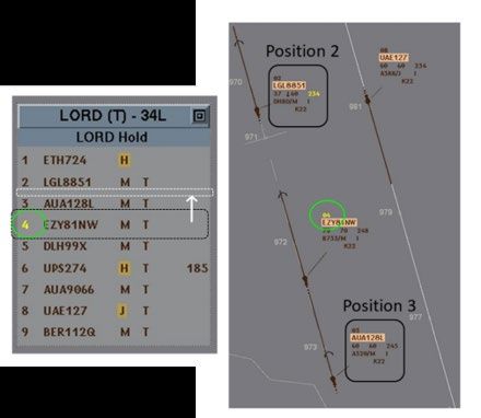
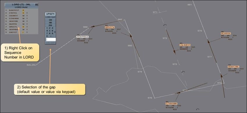
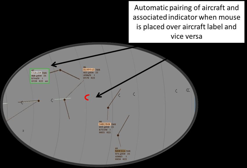
EUROCONTROL Guidelines on Time-Based Separation (TBS) for Final Approach

 4.5.1.2 TBS indicator configuration requirements......................................... 51
 4.5.1.2.1 TBS indicator placement: on the extended runway centerline . 51
 4.5.1.2.2 Synchronisation of HMIs ............................................................. 51
 4.5.1.2.3 Consistency between CWPs ....................................................... 51
 4.5.1.2.4 Customisation of TBS indicator display selection..................... 52
 4.5.1.2.5 Clarity of indicator meaning ........................................................ 52
 4.5.1.2.6 Criteria for displaying TBS indicators ........................................ 52
 4.5.1.2.7 Aircraft association to indicator.................................................. 52
 4.5.1.2.8 Hide feature for visual separations ............................................. 54
 4.5.2 Aircraft sequence list .................................................................................. 54
 4.5.3 Mixed mode operations (GAP insertion for arrivals) ................................. 56
 4.5.4 Mode transition display on the HMI ............................................................ 57
 4.5.5 Alert HMI....................................................................................................... 58
 4.5.6 Operational control and monitoring panel ................................................. 59
 4.6 Working methods with the TBS support tool .................................................... 59
 4.6.1 Sequencing operations ............................................................................... 59
 4.6.2 Final approach ............................................................................................. 59
 4.6.2.1 Working with FTD ................................................................................ 59
 4.6.2.2 Creating situational awareness prior to interception ........................ 60
 4.6.2.3 Interception of the final approach....................................................... 60
 4.6.2.4 Speed control ....................................................................................... 60
 4.6.3 Tower operations ......................................................................................... 60
 4.6.3.1 Working with FTD ................................................................................ 60
 4.6.3.2 FTD infringement ................................................................................. 61
 4.6.4 Mixed mode runway operations (gap insertion for arrivals) ..................... 61
 4.6.5 Mode transition ............................................................................................ 62
 4.7 Alerts .................................................................................................................... 62
 4.7.1 Sequence alert ............................................................................................. 63
 4.7.1.1 Display on the LORD demonstrator.................................................... 63
 4.7.1.2 Required ATCO action ......................................................................... 64
 4.7.2 Speed conformance alert ............................................................................ 64
 4.7.2.1 Display on the LORD demonstrator.................................................... 64
 4.7.2.2 Required ATCO action ......................................................................... 65
 4.7.3 Catch-up alert .............................................................................................. 65
 4.7.3.1 Display on the LORD demonstrator.................................................... 66
 4.7.3.2 Required ATCO action ......................................................................... 66
 4.7.4 TBS infringement risk alerting functions for TWR .................................... 66
 4.7.4.1 TBS infringement risk advisory .......................................................... 67
 4.7.4.2 TBS infringement warning................................................................... 67
 4.7.5 Wrong aircraft type or category alert ......................................................... 67
 4.7.5.1 Required ATCO action (under development): .................................... 67
 4.8 Abnormal and Degraded Mode........................................................................... 67
 4.8.1 Advisory and warning alerts ....................................................................... 68
 4.8.2 TBS indicator calculation ............................................................................ 68
 4.8.3 HMI................................................................................................................ 69
 4.8.3.1 Advisory and warning alerts ............................................................... 69
 4.8.3.2 TBS indicator display .......................................................................... 69
 4.8.4 Working methods ........................................................................................ 70

Edition: 1.0 Released Issue Page 7
EUROCONTROL Guidelines on Time-Based Separation (TBS) for Final Approach

ANNEX A - Guidelines Update Procedures .......................................................... 71

ANNEX B - Time-Based Separation (TBS) Principles as Alternative to Static Distance-
 Based Separation for Final Approach: Safety Case Report ....................... 72

ANNEX C - Traceability to requirements from EUROCONTROL Specification for Time
 Based Separation (TBS) support tool for Final Approach .......................... 73

Page 8 Released Issue Edition: 1.0
EUROCONTROL Guidelines on Time-Based Separation (TBS) for Final Approach

 LIST OF FIGURES
Figure 1: Illustration of the TBS concept .................................................................................. 20
Figure 2: Example of time separation evolution corresponding to a given distance when
 operating DBS (left) or TBS (right) in low or strong headwind conditions. ..................... 21
Figure 3: schematic view of why TBS wake risk remains acceptable compared to DBS. Top:
 Low wind condition, Bottom: Strong headwind condition ............................................... 23
Figure 4: Schematic view of FTD and ITD definition ................................................................ 25
Figure 5: FTD calculation logic for distance-based separation/spacing constraints............. 39
Figure 6: FTD calculation logic for time- and distance-based separation/spacing
 constraints ........................................................................................................................... 41
Figure 7: Sources of uncertainty for FTD calculation of time-based separation/spacing
 constraints ........................................................................................................................... 44
Figure 5: example of Tower view in EUROCONTROL LORD demonstrator ............................ 49
Figure 6: example of Approach view in EUROCONTROL LORD demonstrator ...................... 49
Figure 7: Example of aircraft association to indicator in EUROCONTROL LORD demonstrator
 .............................................................................................................................................. 53
Figure 8: Example of sequence display in EUROCONTROL LORD demonstrator ................. 55
Figure 9: Example of sequence list update in the EUROCONTROL LORD demonstrator ..... 56
Figure 10: Example of Gap management in EUROCONTROL LORD demonstrator ............... 57
Figure 11: Example of sequence alert display in EUROCONTROL LORD demonstration
 tool ........................................................................................................................................ 58
Figure 12: Example of speed conformance alert display in EUROCONTROL LORD
 demonstration tool .............................................................................................................. 58
Figure 13: Example of sequence alert display in EUROCONTROL LORD demonstration
 tool ........................................................................................................................................ 63
Figure 14: Example of speed conformance alert display in EUROCONTROL LORD
 demonstration tool .............................................................................................................. 65
Figure 15: Example of ITD catch-up alert display in EUROCONTROL LORD demonstration
 tool ........................................................................................................................................ 66

Edition: 1.0 Released Issue Page 9
EUROCONTROL Guidelines on Time-Based Separation (TBS) for Final Approach

 EXECUTIVE SUMMARY
This document provides guidelines on the Time-Based Separation (TBS) solution on Final Approach
in view of supporting the local implementation at an Airport and the necessary upgrades to the
Approach and Tower Air Traffic Control Procedures and Systems.
These guidelines provide further illustration in relation to the EUROCONTROL-SPEC-167 on TBS
support tool on final approach, about possible ways to implement the generic requirements to
operate a TBS system. Therefore, the primary target audience is Air Navigation Service Providers,
who will deploy TBS operational systems, and their related ATC system providers, whenever
applicable.
These guidelines are further based on the EUROCONTROL experience on the development and
validation of TBS, working with several European Air Navigation Service Providers through SESAR
1 and SESAR 2020 Industrial Research Program. As part of this cooperation, multiple Real-Time
Simulation campaigns were conducted using the EUROCONTROL TBS/LORD (“Landing with
Optimum Runway Delivery) demonstrator prototype (Separation Delivery tool supporting TBS
application), applied to several European airport environments (Paris CDG, Copenhagen, Vienna,
Zurich, Milano Malpensa). In addition, it also builds on the experience gained as part of the
TBS4LOWW deployment project funded by INEA/CEF under SESAR Deployment Manager (SDM)
coordination.
NATS UK has operationally deployed TBS at London Heathrow and has accumulated experience of
operating TBS at all times (H24) since March 2015.
These guidelines include the following elements:
 • Overview of TBS Principles
 • Guidance on establishing local TBS minima
 • Guidance on generic requirements to operate a TBS system
 • Reference material to support TBS deployment.

Page 10 Released Issue Edition: 1.0
EUROCONTROL Guidelines on Time-Based Separation (TBS) for Final Approach

1. Introduction
1.1 Purpose of the document
This document provides guidelines on the Time-Based Separation (TBS) solution on Final Approach
in view of supporting the local implementation at an Airport and the necessary upgrades to the
Approach and Tower Air Traffic Control Procedures and Systems.
These guidelines provide further illustration in relation to the EUROCONTROL SPEC 167 on TBS
support tool on final approach [RD 1], about possible ways to implement the generic requirements
to operate a TBS system.
These guidelines are further based on the EUROCONTROL experience on the development and
validation of TBS, working with several European Air Navigation Service Providers through SESAR
1 and SESAR 2020 Industrial Research Program. As part of this cooperation, multiple Real-Time
Simulation campaigns were conducted using the EUROCONTROL TBS/LORD (“Landing with
Optimum Runway Delivery) demonstrator prototype (Separation Delivery tool supporting TBS
application), applied to several European airport environments (Paris CDG, Copenhagen, Vienna,
Zurich, Milano Malpensa). In addition, it also builds on the experience gained as part of the
TBS4LOWW deployment project funded by INEA/CEF under SESAR Deployment Manager (SDM)
coordination.
NATS UK has operationally deployed TBS and support tool at London Heathrow - named Intelligent
Approach (‘IA’) separation delivery tool - and has accumulated experience of operating TBS at all
times (H24) since March 2015.

1.2 EUROCONTROL Guidelines
EUROCONTROL guidelines, as defined in EUROCONTROL Regulatory and Advisory Framework
(ERAF), are advisory materials and contain:
“Any information or provisions for physical characteristic, configuration, material, performance,
personnel or procedure, the use of which is recognised as contributing to the establishment and
operation of safe and efficient systems and services related to ATM in the EUROCONTROL Member
States.”
Therefore, the application of EUROCONTROL guidelines document is not mandatory.
In addition, EUROCONTROL Regulatory and Advisory Framework specifies that:
“EUROCONTROL Guidelines may be used, inter alia, to support implementation and operation of
ATM systems and services, and to:
 • complement EUROCONTROL Rules and Specifications;
 • complement ICAO Recommended Practices and Procedures;
 • complement EC legislation;
 • indicate harmonisation targets for ATM Procedures;
 • encourage the application of best practice;
 • provide detailed procedural information.”

1.3 Use of the document
This document is intended to be read and used by all civil and military ATS Providers in the
EUROCONTROL Member States (41) and Comprehensive Agreement States (2).

Edition: 1.0 Released Issue Page 11
EUROCONTROL Guidelines on Time-Based Separation (TBS) for Final Approach

EUROCONTROL makes no warranty for the information contained in this document, nor does it
assume any liability for its completeness or usefulness. Any decision taken on the basis of the
information is at the sole responsibility of the user.

1.4 Maintenance of the Guidelines
This EUROCONTROL Guidelines document has been developed under the EUROCONTROL
Regulatory and Advisory Framework (ERAF) and is maintained by EUROCONTROL in accordance
with this framework and in line with the EUROCONTROL Standards Development Procedures. The
procedures are described in detail in Annex A.

1.5 Conventions
The following conventions used in this EUROCONTROL Guidelines are applicable to the
requirements, which are reproduced from the TBS Specification [RD 1]: The conventions are as
follows:

 a. “Shall” – indicates a statement of specification, the compliance with which is mandatory to
 achieve the implementation of the TBS Specification.
 b. “Should” – indicates a recommendation or best practice, which may or may not be satisfied
 by all systems claiming conformity to the TBS Specification.
 c. “May” – indicates an optional element.
Numbers within square brackets are used to identify reference documents listed in section 1.8, e.g.
[1] identifies the first reference documents of section 1.8.

Every requirement and recommendation in the TBS Specification is followed by a structured
identifier, which can be used to uniquely reference the requirement/recommendation from
associated documents and traceability tools. Such identifiers have the form:

 TBS-[Fn]-[nnn]
 where:
 [Fn]: is a sequence of characters to identify the functional area to which the
 requirement applies, e.g. “FLIGHT” for requirements related to TBS support tool
 flight data inputs;
 [nnn]: is a numeric identifier for a sequence of requirements within the same
 functional area 1.

The functional areas are:
 • FLIGHT: Flight data inputs;
 • SURV: Surveillance data inputs;
 • SEP: Separation data inputs;
 • SPAC: Spacing data inputs;
 • MET: Meteorological data inputs;
 • SEQ: Approach arrival sequence inputs;

1
 Requirement numbers are initially allocated incrementally in tens. This aids the subsequent management of this guidelines document
 allowing new requirements to be inserted between existing requirements whilst maintaining a logical number sequence.

Page 12 Released Issue Edition: 1.0
EUROCONTROL Guidelines on Time-Based Separation (TBS) for Final Approach

 • SPEED: Aircraft speed profile / time-to-fly modelling;
 • CALC: Separation and spacing calculation;
 • COMP: Compression spacing calculation;
 • HMI: Human Machine Interface for Controller Working Positions;
 • SAF: Safety mitigation elements;
 • CNTR: Operational control and monitoring.

1.6 Abbreviations and acronyms
 Abbreviation Term

 3D 3-Dimentional

 ADA Arrival-Departure-Arrival

 AMAN Arrival Manager

 ANSP Air Navigation Service Provider

 APP Approach

 ATC Air Traffic Control

 ATCO Air Traffic Control Officer

 ATM Air Traffic Management

 CALC TBS separation / spacing calculation requirements

 CNTR Operational control and monitoring requirements

 COMP Compression spacing calculation

 CR Change Request

 CSPR Closely Spaced Parallel Runways

 CWP Controller Working Position

 DASC Digital Avionics Systems Conference

 DBS Distance Based Separation

 DDA Departure-Departure-Arrival

 DF Deceleration Fix

 DP Delivery Point

 EASN European Aeronautics Science Network

Edition: 1.0 Released Issue Page 13
EUROCONTROL Guidelines on Time-Based Separation (TBS) for Final Approach

 Abbreviation Term

 EC European Commission

 EU European Union

 ERAF EUROCONTROL Advisory Framework

 FLIGHT Flight data input requirements

 FTD Final Target Distance

 H24 24-Hour Operations

 HMI Human Machine Interface

 ICAO International Civil Aviation Organization

 ICAO WTC ICAO Wake Turbulence Category

 ICAO WTG ICAO Wake Turbulence Groups

 ICAO WT DBS ICAO Wake Turbulence Distance Based Separation

 ITD Intermediate Target Distance

 LiDAR Light Detection and Ranging

 LORD Landing with Optimised Runway Delivery

 LVP Low Visibility Procedures

 MET Meteorological data inputs

 M/L Machine Learning

 MRS Minimum Radar Separation

 MTOM Maximum Take-Off Mass

 NM Network Manager

 ORD Optimised Runway Delivery

 OSED Operational Service and Environment Definition

 PCP Pilot Common Project

 PWS Pair Wise Separation

 RECAT EU Re-categorisation in EU (scheme)

 RECAT PWS Re-categorisation in PWS (scheme)

Page 14 Released Issue Edition: 1.0
EUROCONTROL Guidelines on Time-Based Separation (TBS) for Final Approach

 Abbreviation Term

 ROT Runway Occupancy Time

 RWY Runway

 SAF Safety mitigation element requirements

 SAR Safety Assessment Report

 SEP Separation data inputs

 SEQ Approach arrival sequence inputs

 SESAR Single European Sky ATM Research

 SF Stabilization Fix

 SODAR Sonic Detection And Ranging

 SPAC Spacing data inputs

 STAR Standard Terminal Arrival Route

 SURV Surveillance data input requirements

 T2F Time-to-fly

 TAS True Air Speed

 TBS Time Based Separation

 THR Threshold

 TMA Terminal Control Area

 WT Wake Turbulence

 WTC Wake Turbulence Category

 WVE Wake Vortex Encounter
 Can also be called wake turbulence encounter (WTE)

1.7 Definitions
 Term Definition

Approach Arrival Sequence A list of aircraft presented in the expected order of arrival.

Arrival aircraft Arrival aircraft means those to be sequenced on final
 approach.

Edition: 1.0 Released Issue Page 15
EUROCONTROL Guidelines on Time-Based Separation (TBS) for Final Approach

 Term Definition

Compression distance A distance that represents the amount of compression
 predicted to occur between two aircraft from the time the
 leader passes a defined point (typically the deceleration
 fix) and the time the leader reaches the runway threshold.

Final Target Distance (FTD) A reference on the Final Approach and Tower Runway
indicator CWP to visualise the minimum applicable separation,
 under DBS or TBS operations.

Intermediate Target Distance A reference on the Final Approach and Tower Runway
(ITD) indicator CWP to visualise the predicted compression distance for
 ensuring Optimum Runway Delivery (ORD).

DBS mode A mode of operation when indicators are calculated using
 distance based wake separation rules.

Distance based wake turbulence Wake turbulence radar separation rules defined in distance
radar separation rules which can be category based or aircraft pair based.

Characterisation of aircraft flying A model which defines an expected aircraft ground speed
time / expected ground aircraft profile or time-to-fly model needed for converting time to
speed profile / time-to-fly model distance in the separation / spacing calculation.
 The characterization of flying time profile (also denoted in
 the EUROCONTROL Guidance as time-to-fly profile) is a
 vector providing, for various distances, the time required
 for a flight to travel the reference applicable separation
 distance minima down to landing runway threshold. By
 interpolation in this vector, the flying time can then be
 obtained for any distance down to runway threshold. This
 flying time profile depends on the flight groundspeed
 profile, itself as a function of the flight airspeed profile and
 on the wind profile

Glide-slope wind conditions MET information along the glideslope (At minima from
 threshold to a distance corresponding to the separation
 delivery point plus the maximum separation to apply). Can
 be one or more of wind effect, wind speed and / or wind
 direction.
Indicator A reference on the Final Approach and Tower Runway
 CWP to visualise the indicator distance.
Indicator distance The distance computed for an indicator which represents
 the required separation or spacing.
Individual spacing gaps An increase of separation behind a given aircraft in the
 approach sequence, this one can be, for example,
 requested for clearing a departure in mix mode
In-trail aircraft pair A consecutive pair of aircraft on final approach which are
 using the same final approach track segment.
Minimum radar separation The minimum allowable separation allowed between two
 aircraft based upon the radar performance requirements.

Page 16 Released Issue Edition: 1.0
EUROCONTROL Guidelines on Time-Based Separation (TBS) for Final Approach

 Term Definition
Minimum runway time Is the time separation rule ensuring safe operation on the
separation runway. Primarily, this time separation result from the
 runway occupancy time, but can also be related, for
 example, to other constrain like departure in mix mode or
 runway inspection
Minimum runway spacing Is the spacing rule ensuring safe operation on the runway.
 Primarily, this spacing result from the runway occupancy
 time, but can also be related, for example, to other constrain
 like departure in mix mode or runway inspection
Not-in-trail aircraft pair A consecutive pair of aircraft on final approach which are
 not using the same final approach track segment (i.e.
 parallel runways).
Separation A legal minimum time or distance
 allowed between two aircraft
Separation Delivery tool ATC automation system/tool which
 can be used as TBS support tool
Spacing A time or distance between two aircraft which does not
 represent a separation.
TBS distance The distance that an aircraft will fly for a given time and
 expected groundspeed (considering wind effect)
TBS mode A mode of operation when indicators are calculated using
 time based wake separation rules.
TBS support tool A tool that converts the required time separation / spacing
 into the equivalent distance separation / spacing for the
 prevailing headwind conditions and displays this on the CWP.
Time based wake turbulence Wake turbulence radar separation rules defined in time,
radar separation rules which can be category based or aircraft pair based.

Edition: 1.0 Released Issue Page 17
EUROCONTROL Guidelines on Time-Based Separation (TBS) for Final Approach

1.8 Reference material to support TBS deployment
[RD 1] EUROCONTROL Specification for Time Based Separation (TBS) support tool for Final
 Approach, EUROCONTROL-SPEC-167, dated 01/02/2018
 https://www.eurocontrol.int/publication/eurocontrol-specification-time-based-separation-
 tbs-support-tool-final-approach
The EUROCONTROL TBS Specification document provides a list of functional requirements to
operate TBS with a TBS support tool.
The document provides a list of performance requirements (initially traced to the European “PCP”
716/2014 regulation, now repealed), those TBS Specifications have a voluntary status and were
developed in collaboration with stakeholders from air navigation service provides, airports, aircraft
operators, industry bodies and trade associations.
These specifications are thus not mandatory and provided on a voluntary basis to Member States
and stakeholders to support the TBS deployment.
 • EUROCONTROL ‘generic safety case’
EUROCONTROL has developed a ‘generic safety case’ on TBS principles, addressing the
acceptable level of safety of TBS regarding wake turbulence risk assessment based on LiDAR data-
driven wake decay analysis, and the principle of local TBS minima determination. It aims at avoiding
the need to re-demonstrate TBS principles such as the headwind effect on wake turbulence risk
when deploying TBS.
This TBS Principle Safety Case has been developed by EUROCONTROL and submitted to EASA
in view of supporting the TBS provisions into the EASA regulatory system, and is available on request
to EUROCONTROL (runway-package@eurocontrol.int ) by ANSPs and Authorities engaging into
TBS deployment.
This document presents the safety case on Time-based Separation Minima for Final Approach (TBS
Principles) as alternative to Distance-based Separation. By operating with TBS minima, established
from equivalent time to fly the distance minima in calm wind conditions, the delivered time spacing
between aircraft on final approach will be maintained across headwind conditions. The wake
turbulence encounter risk assessment provides assurance that these TBS minima converted from a
reference distance-based separation (DBS) scheme are acceptably safe due to the effect of wind on
wake decay. Examples of TBS minima obtained from air speed profile measurements are provided
in an Annex of the TBS principle Safety Case document.
The Safety Case report is an integral part of this Guideline document as Annex B.

1.9 Document structure
The document is structured as follows:
 • Section 1 describes the purpose, scope and structure of the document and lists reference
 documents, explains terms and contains a list of abbreviations.
 • Section 2 contains an overview of TBS Principles.
 • Section 3 provides guidance on establishing local TBS minima.
 • Section 4 provides guidance on generic requirements to operate a TBS system.
 • Annex A describes the Guidelines update procedure.
 • Annex B provides the Safety Case report: Time-Based Separation (TBS) Principles as
 Alternative to Static Distance-Based Separation for Final Approach.

Page 18 Released Issue Edition: 1.0
EUROCONTROL Guidelines on Time-Based Separation (TBS) for Final Approach

 • Annex C provides traceability to requirements from EUROCONTROL Specification for Time
 Based Separation (TBS) support tool for Final Approach, EUROCONTROL-SPEC-167 [RD
 1].

Edition: 1.0 Released Issue Page 19
EUROCONTROL Guidelines on Time-Based Separation (TBS) for Final Approach

2. Overview of TBS principles
2.1 TBS Goals
Headwind conditions on final approach cause a reduction of the aircraft ground speed which results
in an increased time separation for each aircraft pair, a reduction of the landing rate, and a lack of
stability of the runway throughput during arrival operations.
This has a negative impact not only on the achieved capacity, generating delays, but also on the
predictability of operations, flight and fuel efficiency.
The Time-Based Separation (TBS) concept is addressing this problem by enabling stable arrival
runway throughput in all headwind conditions on final approach. This is achieved by stabilising the
delivered time spacing between aircraft on final approach across headwind conditions.
TBS consists in the separation of aircraft in sequence on the final approach to a runway using time
intervals instead of distances. These time intervals are established based on the time-to-fly distance
minima between aircraft in low wind conditions.
TBS principle is to maintain equivalent time separation across headwind conditions. This will
result in a reduction of the applicable distance separation minima as the headwind increases.
Figure 1 provides an illustration of the TBS concepts (with indicative example of TBS time values).
Time-Based Separation thus improves the landing rate resilience to headwind conditions on final
approach by recovering the lost landing rate currently experienced when applying distance-based
separation (DBS).

 Figure 1: Illustration of the TBS concept

Page 20 Released Issue Edition: 1.0
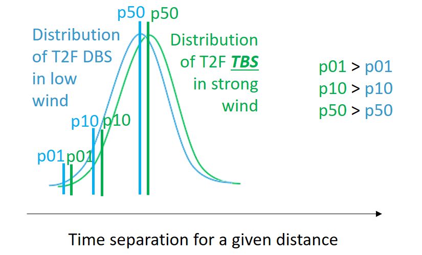
EUROCONTROL Guidelines on Time-Based Separation (TBS) for Final Approach

2.2 Reference TBS minima
The time-based separation minima are derived from the distance-based wake turbulence separation
(DBS) minima in low wind conditions. These reference wind conditions are to be selected locally
and are subject to the local wake risk assessment.
 The wake turbulence risk assessment developed in the TBS Principles safety case relies on low
 wind conditions corresponding to surface wind conditions lower than 5 kts total wind (all
 directions). Therefore, the distance minima reduction resulting from the application of TBS minima
 will become effective as the wind speed increases above 5 kts. Below this threshold or in case of
 tailwind conditions above 5kts, standard distance-based minima remain applicable. Low wind
 conditions therefore typically correspond to headwind component 9 km/h (5 kt) or less.
 However more conservative criteria can be defined and applied locally. As examples, the
 operational threshold for low wind can be raised to:
 - Example #1: 7kts headwind or more, and no tailwind
 - Example #2: ground total wind lower than or equal to 5 kts and with maximum ground tailwind
 of 2 kts
In given wind conditions, for a given aircraft type and for a given DBS minimum, due to the variability
in aircraft flying airspeed, a time separation distribution is observed. When operating DBS, as
headwind increases, this distribution is seen to be shifted towards larger values. This is illustrated in
Figure 2.

 Figure 2: Example of time separation evolution corresponding to a given distance when
 operating DBS (left) or TBS (right) in low or strong headwind conditions.

The objective of TBS is to maintain equivalent time-separation distribution across headwind
conditions. This is achieved through a dynamic reduction of the applicable distance separation
minima as the headwind increases. This constraint can be verified through the comparison of
quantiles, e.g., 1st, 10th and 50th (median) of the time separation distribution in calm wind
conditions.

The TBS minima rules are therefore established from the distribution of equivalent time-to-
fly of the distance minima in low wind conditions.
Alternatively, an approach taken by NATS during the Intelligent Approach (IA) tool implementation
included airline education programme on the significance of conformance to speed instruction on
final approach. As a result, speed monitoring showed an improvement in speed conformance,
allowing reduced variability in aircraft speeds and associated levels of uncertainty.

Edition: 1.0 Released Issue Page 21
EUROCONTROL Guidelines on Time-Based Separation (TBS) for Final Approach

The time intervals can be established from various distance-based separation schemes (e.g.,
ICAO provisions based on Wake Turbulence Categories (WTC), ICAO provisions based on WT
Groups, RECAT-EU, RECAT-EU-PWS), using applicable air speed profiles measurements. The
resulting time distributions will be a function of the separation minima at the separation delivery point
on final approach and must be established on a local basis.
The TBS minima can be established per aircraft type, wake turbulence category or group.

2.3 TBS delivery tool for Controllers
There will be a need to facilitate delivery of time-based separation
minima by the final approach and tower controllers, with a TBS
support tool. It provides a TBS distance indicator, enabling the ATM
system to visualise on the surveillance display the distance
corresponding to the applicable TBS minima, and taking in account
the aircraft airspeed and the prevailing wind conditions.
This indicator support is displayed on the extended runway centreline
of the Final Approach controller and the Tower Controllers surveillance
display.
The TBS support tool will need several inputs to calculate the
appropriate separation / spacing indicators: the approach sequence, the reference time separation
minima, the surveillance info (such as aircraft position) and flight plan info (such as aircraft type), the
applicable time-to-fly characterization (aircraft groundspeed profile) and the wind profile on final.
Intrinsic variability of the aircraft airspeed profile and of the wind generate uncertainty that needs to
be accounted for and factored in the indicator calculation. Buffers are therefore added to cope with
the wind and aircraft airspeed uncertainties.
Depending on the actual set-up of the TBS support tool, and where necessary to mitigate the
identified local hazards, the tool may also feature safety alerting functions to warn in case of wrong
sequence or non-conformant approach airspeed.
Finally, it may also integrate all applicable separation minima (e.g., Wake minima, Minimum Radar
Separation) and spacing (e.g., ROT, Gap) needs.

2.4 Impact on wake turbulence risk
By introducing possible dynamic variation of distance separation minima as a function of head wind,
with the application of fixed TBS minima between successive arrivals, in strong headwind conditions,
due to the distance separation reduction, aircraft pairs will be exposed to reduced wake age
compared to their current situation under DBS wake turbulence scheme application. TBS thus
impacts the wake strength that can be potentially encountered.
Indeed, the headwind component transports the vortices toward the follower aircraft. When applying
DBS, since the distance separation is maintained constant whatever the headwind condition, at first
order, the age of the vortex potentially encountered by the follower remains constant. Conversely,
when applying TBS in prevailing headwind conditions, because the time separation between the
aircraft is maintained constant, the age of the vortex potentially encountered by the follower is
reduced. However, it is known from literature that, close to the ground, which constitutes the design
case, the headwind enhances the wake vortex decay.
Therefore, as illustrated in Figure 3, the enhanced wake decay will be mitigating the effect of
headwind transport blowing younger vortices toward the follower aircraft.

Page 22 Released Issue Edition: 1.0
EUROCONTROL Guidelines on Time-Based Separation (TBS) for Final Approach

Figure 3: schematic view of why TBS wake risk remains acceptable compared to DBS. Top:
 Low wind condition, Bottom: Strong headwind condition

This means, in terms of wake turbulence risk, that the probability per approach of wake turbulence
encounter of a given severity for a given traffic pair at TBS minima on final approach segment and
for any headwind conditions must not increase compared to the same traffic pair spaced at DBS
minima in reasonable worst conditions recognized for WT separation design. This has been shown
through wake turbulence encounter risk assessment based on wake data analysis.
Moreover, as demonstrated in EUROCONTROL Safety Case on TBS principles (see Annex B) in
case of strong wind conditions, the positive impact of the total wind on the wake decay allows for
further reduction of the time separations even below the TBS minima. Those TBS margins depend
on the total surface wind.
In terms of impact on overall probability of wake vortex encounter, the impact can be expected to be
limited and around 5 to 10% potential increase, since:
 • In low wind, there will be no difference between TBS and DBS in terms of risk exposure
 (since in low wind the TBS spacing are by definition equal to the DBS),
 • In moderate to strong headwind, there might be an increase due to the exposure to younger
 wakes, however in those conditions the wind impacts both the wake decay and transport,
 limiting the overall risk of wake vortex encounter
Wake Vortex Encounter (WVE) reports statistics from a major European airport show that about 15%
of WVEs are reported under moderate to strong headwind conditions. If the encounter probability
increases by, e.g., 50% under these moderate to strong headwind conditions, this then represents
an overall increase between 5 and 10%. This percentage increase is provided for guidance only and
does not eliminate the need for the assessment of the local wake risk”.

Edition: 1.0 Released Issue Page 23
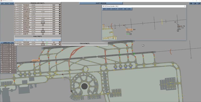
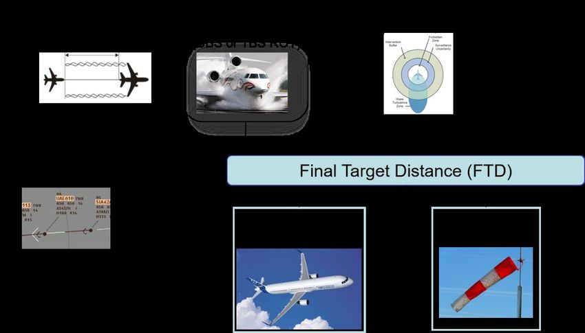
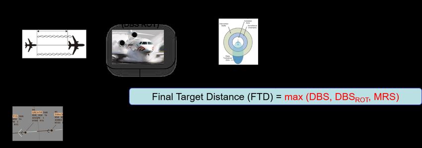
EUROCONTROL Guidelines on Time-Based Separation (TBS) for Final Approach

However, NATS UK has reported that the operational use of TBS (deployed in 2015) at London
Heathrow has delivered significant arrival throughput and performance benefits, and this has all been
achieved without any increase in reported wake vortex encounters or go-arounds.”

2.5 Optimised Runway Delivery (ORD), complementing TBS
In order to safely deliver the separation at the separation delivery point (typically the runway
threshold), the Controllers usually takes some buffers when spacing the traffic on final. These buffers
are taken by experience of the expected traffic airspeed behaviour (compliance to ATC airspeed
instruction and typical landing airspeed), and can lead to an average over-separation between
0.5NM and 1NM (above the applicable minima).
These buffers also result from the uncertainty related to the compression between traffic on final due
to the natural distance catch-up and the difference in final approach airspeeds.
Therefore, an aircraft behaviour prediction can enable improved separation delivery performance
compared to today, while maintaining or even reducing the associated ATCO workload.
Moreover, when applying TBS, due to the significant variation in applicable separation minima, the
compression buffers can no longer be accurately estimated by the controllers. There is thus a need
for a separation support tool to also provide this information.
In the ORD concept, the Controllers are presented with information of the applicable spacing, based
on the predicted compression between successive arrivals on final, in order to accurately and
efficiently deliver the separation minimum at the separation delivery point (i.e., runway threshold).
It must be noted that ORD necessitates an accurate aircraft groundspeed prediction across operating
conditions, for ensuring safety but also for efficiency as a too conservative definition of buffer can
lead to a reduction of efficiency.
The TBS and ORD solutions deliver significant operational benefits:
 • full resilience to headwind,
 • increased separation delivery efficiency enabled by the use of a Separation Delivery tool,
 • increased safety by reducing risk of loss of separation on final,
 • maintained or reduced Controller workload.

This tool then also enables the integration of other and more complex separation and spacing rules
(e.g. static wake turbulence pair-wise separation, also called RECAT-PWS), which further increase
efficiency in runway usage.
Those solutions can deliver up to 15% runway throughput gain depending on the airport operating
environment and traffic mix.

2.6 EUROCONTROL LORD Demonstrator
EUROCONTROL has developed a demonstrator of separation delivery tool, called LORD (Landing
with Optimised Runway Delivery) that can be used as TBS support tool. In LORD, a TBS and an
ORD indicator are used and displayed on the Controller Working Position HMI:
 - a separation minimum distance indicator (Final Target Distance – FTD), enabling
 the ATM system to visualise on the surveillance display the distance corresponding to

Page 24 Released Issue Edition: 1.0
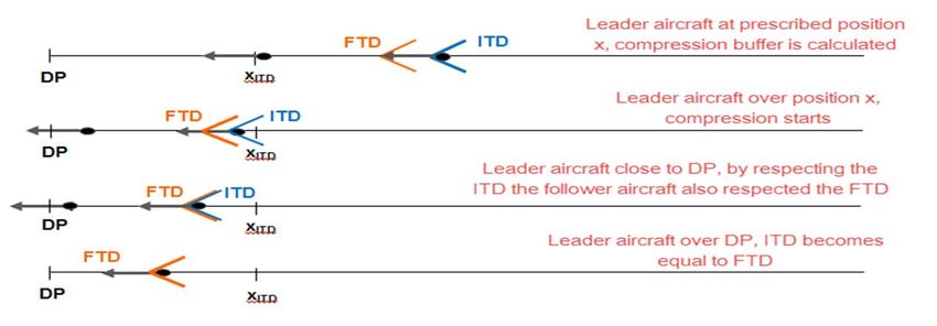
EUROCONTROL Guidelines on Time-Based Separation (TBS) for Final Approach

 the applicable TBS minima, and taking into account the aircraft airspeed
 performance and prevailing wind conditions.
and in addition
 - an Intermediate Target Distance (ITD), as separation delivery aid for Controllers, to
 optimise the compression buffers and ensuring optimum runway delivery (ORD).

The FTD indicator corresponds to the minimum distance separation to be applied between leader
and follower, when the leader is overflying the separation delivery point (e.g., the runway threshold).
The FTD shall account for all applicable separations and spacing constraints (e.g., wake turbulence,
runway occupancy time, surveillance) in the prevailing wind conditions.
The ITD indicator is giving the ATCO information about how to separate the aircraft at a pre-agreed
speed in order to have separation reserve for anticipating on compression effect. When operating
TBS, the compression effect is indeed more complicated to anticipate due to the larger variability in
applicable separation minima. The ITD is the distance separation applicable when the leader aircraft
is at a prescribed glide speed before deceleration to final approach speed such that the FTD will be
obtained at the separation Delivery Point (DP).

 Figure 4: Schematic view of FTD and ITD definition

To prevent spacing infringement, different support alerts are also implemented in the tool. These
alerts are to be used as safety nets to quickly identify potential issues in the approach/landing phase
and allow the controller to take corrective actions.
The LORD demonstrator separation support tool is also able to account for and to provide indication
of more complex business rules to the ATCOs such as Runway Occupancy Time, Spacing gap for
departure, pairwise wake separation minima, weather dependent separation, separation
increase/reduction in case of Enhanced Approach Procedure operation.
The LORD demonstrator was used by Air Traffic Controllers during Real-Time Simulation campaigns
with several airport environments (incl. Vienna, Paris, Copenhagen, Zurich, Milan).

2.7 TBS deployment in Europe
Time Based Separations operations have been in operations at all times (H24) at Heathrow Airport
since March 2015. Then, the separation delivery tool in use at Heathrow was further enhanced in
March 2018 with the inclusion of ORD and RECAT-EU concepts.

Edition: 1.0 Released Issue Page 25
EUROCONTROL Guidelines on Time-Based Separation (TBS) for Final Approach

Several projects for the deployment of TBS, ORD and related concepts are currently on-going in
Europe.
The EUROPEAN ATM MASTER PLAN Level 3 - Implementation plan reports the current situation
of TBS deployment in Europe:
https://www.eurocontrol.int/publication/european-atm-master-plan-implementation-plan-level-3
https://www.atmmasterplan.eu/downloads

Page 26 Released Issue Edition: 1.0
EUROCONTROL Guidelines on Time-Based Separation (TBS) for Final Approach

3. Guidance on establishing local TBS Minima and
 Flying Time characterisation
The TBS concept application relies on the following key steps:
 1) TBS wake turbulence minima are locally established (derived from any distance-based
 separation scheme and flight time characteristics)
 2) Applicable TBS minima is determined for a given aircraft pair (based on type, group or
 category) of arrival traffic
 3) The equivalent distance separation minimum to be delivered is determined by taking into
 account the wind conditions
 4) The distance minimum can be capped, to conform to surveillance minima as applicable.

3.1 TBS Configuration checklist
3.1.1 Definition of applicable Wake Separation Minima
 • Selection of Reference Distance-Based wake turbulence Separation scheme
The reference applicable DBS wake Turbulence scheme is required to display the applicable wake
turbulence separation minima in DBS mode and to calculate the corresponding TBS minima in TBS
mode.
TBS can be derived and operated from the following reference schemes:
 • ICAO legacy wake separation based on wake turbulence categories
 • RECAT-EU (ref. EASA 2020/469 AMC7 to ATS.OR.220)
 • ICAO enhanced wake separation based on wake turbulence groups
 • RECAT-EU-PWS
 • Any other local/national distance-based scheme approved by local authority

 • Selection whether the tool will operate in Time-Based or in Distance-Based mode
If TBS is applied, the TBS minima will be converted into distance indicators varying depending on
the wind conditions. In DBS mode, static separation minima are applied.

3.1.2 Definition of applicable Surveillance minimum (MRS)
Depending on the Radar Surveillance performance, the applicable Minimum Radar Separation
(MRS) rules shall be provided to the TBS support tool .

3.1.3 Definition of ROT spacing constraints
Specific ROT spacing rules (if any) are also required as input for the TBS support tool

3.1.4 Definition of all use cases that shall be accounted for by the TBS
support tool
A complete list of use cases shall be provided in order to allow development of all corresponding
functionalities in the TBS support tool (e.g., single runway, Parallel dependent or independent
runway, mixed runway mode with Gap, low visibility, runway change, Go around)

Edition: 1.0 Released Issue Page 27
You can also read