AIRCRAFT SERIOUS INCIDENT INVESTIGATION REPORT - AI2020-3
←
→
Page content transcription
If your browser does not render page correctly, please read the page content below
AI2020-3

   AIRCRAFT SERIOUS INCIDENT
      INVESTIGATION REPORT

THAI AIRWAYS INTERNATIONAL PUBLIC CO., LTD.
                 HS-TGX

                 July 30, 2020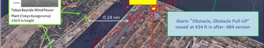
The objective of the investigation conducted by the Japan Transport Safety Board in accordance with
the Act for Establishment of the Japan Transport Safety Board (and with Annex 13 to the Convention on
International Civil Aviation) is to prevent future accidents and incidents. It is not the purpose of the
investigation to apportion blame or liability.

                                                             TAKEDA Nobuo
                                                             Chairman
                                                             Japan Transport Safety Board

                                                     Note:
     This report is a translation of the Japanese original investigation report. The text in Japanese shall
prevail in the interpretation of the report.
AIRCRAFT SERIOUS INCIDENT INVESTIGATION REPORT

EMERGENCY OPERATION TO AVOID CRASH INTO THE GROUND
     THAI AIRWAYS INTERNATIONAL PUBLIC CO., LTD.
                BOEING 747-400, HS-TGX
             ABOUT 3.5 NM NORTHEAST OF
        TOKYO INTERNATIONAL AIRPORT, JAPAN
             AT ALTITUDE OF ABOUT 300 FT
            AROUND 23:52 JST, APRIL 11, 2018

                                                      June 19, 2020
                         Adopted by the Japan Transport Safety Board
                                   Chairman   TAKEDA Nobuo
                                   Member     MIYASHITA Toru
                                   Member     KAKISHIMA Yoshiko
                                   Member     MARUI Yuichi
                                   Member     MIYAZAWA Yoshikazu
                                   Member     NAKANISHI Miwa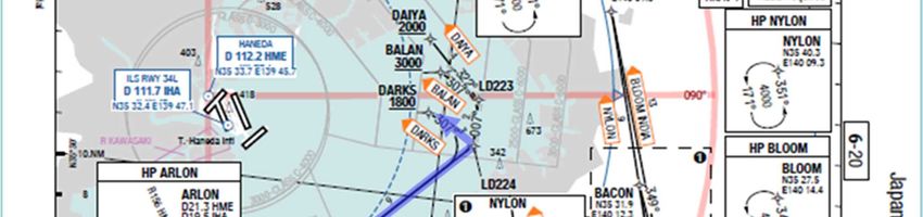
SYNOPSIS

     On April 11, 2018, around 23:52 JST, a Boeing 747-400, registered HS-TGX, operated by Thai
Airways International Public Co., ltd. as a scheduled flight 660 for Tokyo International Airport,
executed a go-around as an emergency operation to avoid crash into the ground in approach to
Runway 16L. The aircraft thereafter requested an approach to land on Runway 22 and landed on
Runway 22 around 00:04 on the following day.
     There were 384 persons onboard, consisting of the PIC, 18 flight crew members and 365
passengers. No one was injured and there was no damage to the Aircraft.

     In this serious incident, it is probable that the Aircraft maneuvered an emergency operation
to avoid crash into the ground because it came close to the ground surface in approach to Runway
16L at Tokyo International Airport.
     It is probable that coming close to the ground was caused by the PIC’s concentration on
modifying the lateral flight path, continuing descent without paying an appropriate attention to
the descent path, and by the first officer’s unawareness of the too low descent path due to his
concentration on monitoring the lateral flight path.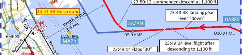
Abbreviations and acronyms used in this report are as follows:
AIP:             Aeronautical Information Publication
AP:              Auto Pilot
ATIS:            Automatic Terminal Information Service
CVR:             Cockpit Voice Recorder
DME:             Distance Measuring Equipment
EGPWS:           Enhanced Ground Proximity Warning System
FAF:             Final Approach Fix
FCOM:            Flight Crew Operations Manual
FCTM:            Flight Crew Training Manual
FDR:             Flight Data Recorder
FMS:             Flight Management System
FO:              First Officer
fpm:             feet per minute
GPWS:            Ground Proximity Warning System
HDG:             Heading
ILS:             Instrument Landing System
LDA:             Localizer Type Directional Aid
LOC:             Localizer
MAC:             Mean Aerodynamic Chord
MDA:             Minimum Descent Altitude
MLIT:            Ministry of Land, Infrastructure, Transport and Tourism
NAP:             Noise Abatement Procedures
ND:              Navigation Display
OM:              Operations Manual
PAPI:            Precision Approach Path Indicator
PF:              Pilot Flying
PIC:             Pilot in Command
PM:              Pilot Monitoring
QAR:             Quick Access Recorder
RFCF:            Runway Field Clearance Floor
VOR:             VHF Omnidirectional Radio Range
VOLMET:          Voice Language Meteorological Report
VS:              Vertical Speed

Unit Conversions
1 ft:                      0.3048 m
1 kt:                      1.852 km/h (0.5144 m/s)
1 nm:                      1,852 m
1 lb:                      0.4536 kg
1 atmospheric pressure: 1,013 hPa, 29.92 inHg
1       PROCESS AND PROGRESS OF THE AIRCRAFT SERIOUS

INCIDENT INVESTIGATION

1.1     Summary of the Serious Incident
      On April 11, 2018 around 23:52 JST (JST: UTC+9 hours; unless otherwise noted, all times are
indicated in JST in this report on a 24-hour clock), a Boeing 747-400, registered HS-TGX, operated
by Thai Airways International Public Co., ltd. as a scheduled flight 660 for Tokyo International
Airport, executed a go-around as an emergency operation to avoid crash into the ground in approach
to Runway 16L. The aircraft thereafter requested an approach to land on Runway 22 and landed on
Runway 22 around 00:04 on the following day.
      There were 384 persons on board, consisting of the PIC, 18 crew members and 365 passengers.
No one was injured and there was no damage to the Aircraft.

1.2     Outline of the Serious Incident Investigation
      The occurrence falls under the category of Article 166-4 (v) “Case where aircraft crew executed
an emergency operation during flight in order to avoid crash into water or contact on the ground” of
the Ordinance for Enforcement of the Civil Aeronautics Act of Japan, and is classified as a serious
incident.

1.2.1       Investigation Organization
      Upon receipt of the notice of the occurrence of the serious incident, the Japan Transport Safety
Board designated an investigator-in-charge and three investigators to investigate the serious
incident.

1.2.2       Representatives of the Relevant State
      An accredited representative of the Kingdom of Thailand, as the State of Operator and Registry
of the aircraft involved in the serious incident, participated in the investigation. The occurrence was
notified to the United States of America, as the State of Design and Manufacture of the aircraft, and
their accredited representative was not designated.

1.2.3       Implementation of Investigation
      April 17, 2018       Confirmation of radar track records and ATC communications
      April 20, 2018       Interviews
      April 25, 2018       Interviews

1.2.4       Comments from Parties Relevant to the Cause of the Serious Incident
      Comments were invited from the parties relevant to the cause of the serious incident.

1.2.5       Comments from Relevant States
      Comments were invited from the relevant states.

                                                 -1-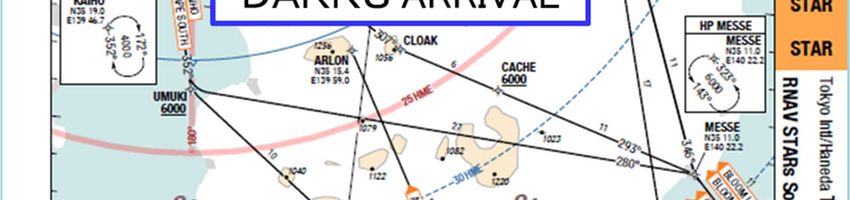
2        FACTUAL INFORMATION

2.1        History of the Flight
       On April 11, 2018, a Boeing 747-400, registered HS-TGX (hereinafter referred to as “the
Aircraft”), operated by Thai Airways International Public Co., ltd. (hereinafter referred to as “the
Company”) as a scheduled flight 660, was in flight from Suvarnabhumi International Airport of the
Kingdom of Thailand to Tokyo International Airport (hereinafter referred to as “the Airport”). In
approach to Runway 16L at the Airport, the Aircraft executed a go-around as an emergency
operation to avoid crash into the ground around 23:52. The Aircraft thereafter requested an
approach to land on Runway 22 and landed on the runway around 00:04 on the following day.
       Outline of the flight plan of the Aircraft was as follows:
       Flight rules: Instrument flight rules (IFR), Departure aerodrome: Suvarnabhumi International
       Airport, Off-block time: 18:20, Cruising speed: 500 kt, Cruising altitude: FL*1 370,
       Destination aerodrome: Tokyo International Airport, Total estimated elapsed time: Five hours
       and 19 minutes, Fuel loaded expressed in endurance: Seven hours and 31 minutes, Alternative
       aerodrome: Kansai International Airport
       At the time of the occurrence of the serious incident, the PIC was sitting in the left pilot’s seat
as PF*2 and the first officer (hereinafter referred to as “the FO”) on the right pilot’s seat as PM*2.
       From the records of QAR*3 and Enhanced Ground Proximity Warning System (hereinafter
referred to as “EGPWS”), ATC communications records and statements of flight crew members and
air traffic controller (hereinafter referred to as “the Controller”), the history of the flight up to the
serious incident was outlined as follows.

2.1.1 History of the Flight based on the Records of QAR, EGPWS and ATC
Communications
       18:44:30          Autopilot (hereinafter referred to as “AP”) of the Aircraft was engaged after take-
                          off from Suvarnabhumi International Airport. The Aircraft continued flight by
                          AP until just before landing on Runway 22 at the Airport.
       23:31:46          The Aircraft conducted the initial contact with the approach controller at Tokyo
                          Terminal Radar Control Facility*4 (hereinafter referred to as “Tokyo Approach”)
                          with ATIS Information “B”*5 attached.
       23:31:52          Tokyo Approach notified the Aircraft that landing was on Runway 16L via VOR
                          A (for RWY 16R/RWY 16L) approach* 6 (hereinafter referred to as “VOR A
                          approach”) to Runway 16L was expected and the Aircraft read back.

*1 "FL" stands for flight level and is pressure altitude of the standard atmosphere. It is the altitude indicated by value divided by
100 of the index of the altitude indicator (unit: ft) when QNH is set to 29.92 inHg. FL is usually applied when flight altitude is
14,000 ft or above in Japan. E.g., FL 370 indicates an altitude of 37,000 ft.
*2 “PF” and “PM” are terms used to identify pilots by their roles when an aircraft is operated by two pilots. The PF is an
abbreviation of Pilot Flying and is mainly responsible for maneuvering the aircraft. The PM is an abbreviation of Pilot Monitoring
and monitors flight status, cross-checks operations of PF and undertakes tasks other than maneuvering the aircraft.
*3 “QAR” is an abbreviation of Quick Access Recorder and is a recording device capable of accumulating flight data almost
equivalent to FDR and allows operators to set their own parameters.
*4 “Terminal Radar Control Facility” denotes a facility that provides terminal radar control services and approach control
services.
*5 “ATIS Information” is provided for aircraft arriving at or departing an airport. The information includes type of approach,
runway in use, conditions of the airport, weather information and so on. See 2.6.2 for ATIS Information “B”.
*6 See 2.9.1 and Appended Figure 4 for “VOR A (for RWY 16R/RWY 16L) approach”.
                                                                -2-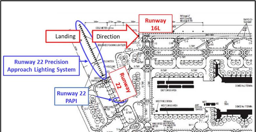
23:40:16 The Aircraft notified Tokyo Approach that it was approaching UMUKI*7 and
requested a type of arrival after passing over KAIHO*8.
23:40:20 Tokyo Approach instructed the Aircraft to descend to an altitude of 4,000 ft via
DARKS*9 ARRIVAL*10 after passing over KAIHO and the Aircraft read back.
23:42:46 The Aircraft asked Tokyo Approach to confirm whether it may descend to an
altitude of 1,800 ft within the path of DARKS ARRIVAL (between KAIHO and
DARKS).
23:45:11 Tokyo Approach cleared VOR A approach via DARKS ARRIVAL to the Aircraft
and the Aircraft read back.
23:47:49 The Aircraft passed over DARKS.
23:48:48 Landing gear lever was operated to the down position.
23:49:01 HDG*11. in the AP lateral mode was selected.
23:49:04 The Aircraft descended to an altitude of 1,100 ft, followed by entering level flight.
23:49:14 Flaps was set to “30” (the Aircraft estimated the landing configuration) and the
speed became 150 kt.
23:49:18 The Aircraft was transferred to the Controller in charge of airport traffic control
in Tokyo Airport Traffic Control Tower (hereinafter referred to as “Tokyo Tower”).
23:49:31 Tokyo Tower notified the Aircraft of the wind direction 200 o and wind velocity 12
kt, and cleared landing on Runway 16L.
23:49:56 The Aircraft commenced circling approach with turning right after passing over
SAZAN*12 (FAF*13), and entered the down-wind leg. The width of the down-wind
leg became about 3.6 nm.
23:50:12 VS*14 in the AP vertical mode was selected and descent for landing commenced
from an altitude of 1,100 ft.
23:50:40 The Aircraft commenced the left turn as the base turn.
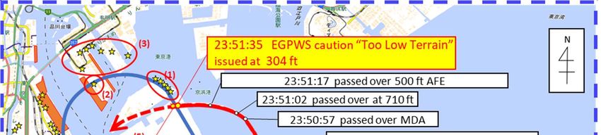
23:50:57 Passed over MDA*15 (altitude 760 ft).
23:51:02 Passed over an altitude of 710 ft.
23:51:17 Passed over an altitude of 521 ft, the aerodrome elevation 21 ft plus 500 ft
(hereinafter referred to as “500 ft AFE”).
23:51:24 Tokyo Tower advised the Aircraft, “Your altitude is too low, confirm, do you have
Runway 16L insight?”
23:51:33 The Aircraft responded to Tokyo Tower saying, “Negative”
23:51:35 EGPWS caution “TOO LOW TERRAIN*16” was enunciated (at altitude 304 ft).
23:51:38 The Aircraft reported to Tokyo Tower “Now going around” and executed it. The
lowest altitude the Aircraft recorded was 282 ft.
*7 See Appended Figure 1 and 3 for “UMUKI”.
*8 See Appended Figure 1 and 3 for “KAIHO”
*9 See Appended Figure 1, 3 and 4 for “DARKS”
*10 “DARKS ARRIVAL” denotes standard instrument arrival procedure connecting to DARKS point. (See Appended Figure 1 and
3)
*11 “HDG (mode)” denotes a flight mode with heading (HDG: Heading) set.
*12 See Appended Figure 1 and 4 for “SAZAN”.
*13 “FAF” is an abbreviation of Final Approach Fix and denotes the fix that is set at the point where the final approach segment
commences in instrument approach procedures. FAF has same meaning as the descent fix in precision approach, and in non-
precision approach denotes the point where the final descent commences. Furthermore, the fix (FIX) denotes a topographical
specific position obtained by means of ground visibility, utilization of radio facilities, celestial navigation and others.
*14 “VS (mode)” denotes climbing or descending mode with the climb or descent rate (VS: Vertical Speed) set.
*15 “MDA” denotes the minimum descent altitude in non-precision approach.
*16 See 2.12.1 (1) for “TOO LOW TERRAIN”.
-3-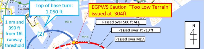
23:51:41          Tokyo Tower instructed the Aircraft to climb in the direction 200 o and an altitude
                         3,000 ft and the Aircraft read back.
       23:53:53          The Aircraft requested landing on Runway 22, which was cleared.
       00:04:20          The Aircraft landed on Runway 22.
       (See Appended Figure 1 and 2)

2.1.2       Statements of Parties relevant to the Serious Incident
  (1) PIC
              The PIC was in good physical condition on the day of the serious incident.
              The PIC went to an originally planned aircraft with flight crew members after completing
        preparations, and was informed by flight dispatcher that the operation would be performed by
        an alternative aircraft due to some malfunction in the originally planned aircraft. Due to the
        aircraft change, the PIC was back to the operation center with the crew members awaiting the
        alternative aircraft to arrive. While awaiting the arrival of the alternative aircraft, the pilot
        went to the dispatch center with the FO to alter the flight plan and to reconfirm meteorological
        conditions and NOTAM*17. The departure was forced to delay by three hours awaiting the
        arrival of the alternative aircraft.
              Because the PIC was unable to receive the meteorological information for the Airport
        from VOLMET broadcast*18 in flight to the Airport despite his attempt, he predicted from
        wind forecast of Aerodrome Forecast (TAF) he obtained prior to the departure that runway in
        use would be 22, and performed approach briefing with the FO .
              When getting close to the Airport, the PIC received the latest information for the Airport
        through ATIS Information “B”. Because runway in use was 16L and approach type was VOR
        A approach, the PIC prepared pertinent charts (“DARKS ARRIVAL chart” (see Appended
        Figure 3), “VOR A approach procedure chart” (Appended Figure 4) and “Noise abatement
        procedures and approach guidance lights chart*19” (Appended Figure 5)), asked the FO to re-
        input aeronautical radio navigation facilities and FMS*20, and performed briefing again by
        reaching UMUKI. The PIC and the FO mutually confirmed in the briefing that the flight
        course for landing on Runway 16L was designated at the Airport and it was important to fly
        on the designated course. Besides, it was also confirmed that, in approaching, PF watched
        outside the aircraft to find out runway and PM monitored instruments in the aircraft.
              The Aircraft approached the Airport from DARKS ARRIVAL via VOR A approach.
              After passing over DARKS, the PIC extended landing gears, descended to an altitude of
        1,100 ft, followed by setting Flaps to “30” to establish landing configuration. The PIC made a
        plan to commence circling approach*21 at an altitude of 1,100 ft without descending down to
        MDA (altitude 760 ft) after SAZAN because cloud base was high and visibility was good enough.
              After passing over SAZAN, the PIC visually recognized Runway 16L at the front. After
        informing the FO of visual recognition of Runway 16L, the PIC commenced circling approach

*17 “NOTAM” is one of the navigational information notified without delay to personnel involved in flight operations with regard
to the establishment status or change in condition of any aeronautical facilities, services, procedures or hazard.
*18 “VOLMET broadcast” provides aircraft in flight with meteorological information by means of voice broadcast. There exist two
different versions; wide area broadcast using HF and regional one using VHF (only the former is operated in Japan).
*19 See Appended Figure 5 for “Noise abatement procedures and approach guidance lights chart”.
*20 “FMS” is an abbreviation of Flight Management System, which assists crew members with navigation, performance, fuel
monitoring and display in cockpit.
*21 “circling approach” denotes a landing procedure conducted by approaching an airport in accordance with the instrument
approach procedure, and then, altering flight course after visually sighting the airport or runway, followed by visual flight in
circling approach area toward landing runway.
                                                              -4-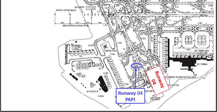
with turning right at an altitude of 1,100 ft and at a speed of 150 kt in a direction 094 o and at
       a distance 4 DME*22 from Haneda VOR/DME as a reference.
              In the down-wind leg, the PIC visually recognized Runway 16L on the left side all the
       time. At that time, the PIC could not visually recognize approach guidance lights ((1) in
       Appended Figure 1), which should have been seen ahead on the right; however, he could
       visually recognize a landmark beacon ((2) in Appended Figure 1) ahead on the left. Approach
       guidance lights ((3) in Appended Figure 1) located at the end of the landmark beacon could not
       be seen because they were merged with lights of the town.
              The PIC commenced descent for landing using VS mode such that the altitude at to the
       point of 1 nm from Runway 16L threshold on the final leg becomes 300 ft. At that time, the
       PIC selected a shallow descent rate because of a long distance to runway. The PIC let the FO
       to watch outside the aircraft by shifting his eyes from instrument monitors in the aircraft to
       find the approach guidance lights ((1) in Appended Figure 1). Both the PIC and the FO visually
       recognized lights that appeared to be the approach guidance lights ahead in the left, and then
       mutually confirmed that the lights were the approach guidance lights.
              The PIC commenced base turn with turning left in an attempt to enter inside the
       designated course using the landmark beacon (Appended Figure 1-(2)) as a reference because
       the PIC realized that the Aircraft was off the designated course.
              The FO performed call-out procedures in accordance with the stipulations pertinent to
       stabilized approach*23 when passing over 500 ft AFE. The PIC continued approach saying,
       “CHECK, CONTINUE” in response to the call-out of the FO because runway was always
       visible.
              During base turn, Tokyo Tower advised the Aircraft, “Your altitude is too low, confirm, do
       you have Runway 16L insight?”
            Due to a low altitude, the PIC could not visually recognize approach light beacon of
       Runway 16L ((4) in Appended Figure 1) blocked by the container piers ahead on the left and
       lost sight of Runway 16L.
               The PIC judged that the Aircraft came too close to the ground surface, and executed a
       go-around to avoid collision with it because EGPWS caution “TOO LOW TERRAIN” was
       enunciated when he reported to Tokyo Tower “Negative”. After executing a go-around, the PIC
       requested approaching to land on Runway 22 and landed on the runway by LDA Y RWY 22
       approach.
               After completion of the flight, the PIC reported to operation control supervisor of the
       Company what had occurred in flight.
               The PIC had experienced landing at the Airport a number of times and had never mixed
       up Runway 22 with Runway 16L; however, this was his first time VOR A approach. The PIC
       had not received simulator training.
  (2) The FO
               The FO was in good physical condition on the day of the serious incident.

*22  “DME” is an abbreviation of Distance Measuring Equipment and denotes an equipment that transmits electronic wave from
aircraft to ground radio station and translates the time required for a round trip of the electronic wave into distance, and shows
estimated distance between the aircraft and the ground station in nautical miles. For example, 4 DME indicates that a line-of-
sight distance between aircraft and ground station is 4 nm.
*23 See 2.10.3 for “stabilized approach”.
                                                               -5-
The flight was smooth at take-off and in cruising. The FO attempted to reset FMS to
approach the Airport in accordance with the instruction from the PIC after receiving ATIS “B” of
the Airport; however, VOR A approach was not registered in FMS navigation data base. In dealing
with that, after inputting DARKS ARRIVAL, the FO inputted SAZAN after DARKS, which was the
final point of DARKS ARRIVAL and then created a FIX at a point 1 nm from Runway 16L threshold
on the final leg to make them references course. (See Figure 1)
Figure 1: Estimated navigation display (ND) (for image only) when resetting FMS
While flying over the final approach path (from DARKS to SAZAN), the FO offered the
PIC that the FO would assist the PIC in finding the approach guidance lights ((1) in Appended
Figure 1), which were difficult to visually recognize from the left pilot’s seat of the PIC.
Asked by the PIC whether the FO could visually recognize the approach guidance lights
((1) in Appended Figure 1) ahead on the right when the Aircraft entered the down-wind leg
while turning to the right after passing over SAZAN, the FO shifted his eyes from instrument
monitors inside the aircraft to the outside, and he could not confirm the lights ahead on the
right. However, the FO became aware that the width of down-wind leg was wide because he
confirmed the lights that appeared to be the approach guidance lights ahead on the left. the
FO advised the PIC that the lights should have been seen on the right side under ordinary
circumstances, and shifted his eyes to the inside of the aircraft again to perform instrument
monitoring. The PIC commenced base turn with turning left in an attempt to fly inside the
designated flight course (blue line in Appended Figure 1).
The FO performed call-out procedures in accordance with stipulations pertinent to
stabilized approach when passing over 500 ft AFE. the FO called out “500 ft, STABILIZED”
because he could always visually recognize runway.
Then, while the FO was monitoring the flight path on the navigation display (hereinafter
referred to as “ND”), the PIC attempted to intercept the point of 1 nm from Runway 16L
threshold on the final leg; however, there was not enough airspace to allow the flight path to
be modified because the Aircraft entered the inside excessively. Therefore, the FO pointed out
to the PIC that it would be difficult to intercept the point.
At that time, there was advice from Tokyo Tower saying, “Your altitude is too low, confirm,
do you have Runway 16L insight?” The PIC seemed to be concentrating on flying inside the
designated flight course and modifying the course, and upon receipt of the advice, he
commenced to search for Runway 16L. However, it seemed that the sight of Runway 16L was
blocked by the container piers ahead on the left and the PIC could not visually recognize them.
-6-When the PIC said, “Negative”, and the FO reported it to Tokyo Tower, EGPWS caution “TOO
LOW TERRAIN” was enunciated, and the PIC executed a go-around.
The FO had experienced landing at the Airport; however, this was his first time VOR A
approach, and he had not received simulator training.
(3) Tokyo Approach
Crew members of the Aircraft had a creditable communication ability with the Controller
and occasionally confirmed a type of arrival after KAIHO. Tokyo Approach was impressed that
the crew members were thinking what would occur ahead in flight and comprehended flight
rules of the Airport. They steadily controlled the aircraft on DARKS ARRIVAL and proceeded
to VOR A approach without overshooting.
Tokyo Approach kept monitoring the Aircraft at radar position even after it had been
transferred to Tokyo Tower. The Controller in the next seat (radar coordination position) was
advising Tokyo Tower, “Is the Aircraft going to Runway 22?”, because the Aircraft was at a low
altitude and on the track that appeared to be heading for Runway 22 due to early
commencement of turning to the right in the northern direction to enter circling approach and
early commencement of descent after entering circling approach.
(4) Tokyo Tower
Tokyo Tower received control transfer of the Aircraft after it had passed over DARKS.
Right turn for circling approach seemed a bit far from runway; however, it didn't seem to
be of great concern..
Descending altitude of the Aircraft in addition to early timing of base turn made Tokyo
Tower wonder whether the Aircraft misunderstood the landing runway was Runway 22, and
accordingly advised, “Your altitude is too low, confirm, do you have Runway 16L insight?” with
the response of “Negative”. While Tokyo Tower was coordinating with approach control
coordinator position to let the Aircraft go around, the Aircraft reported, “Now going around”
Lightings pertinent to Runway 22 were; precision approaching lighting system was turned
off, and lightings such as PAPI that could be switched to runway 04 side were illuminated on
runway 04 side to avoid misrecognition of preferential landing runway of 16L. (See Figure 2)
-7-Figure 2: Runway 22 Precision Approach Lighting System and Runway 04/22 PAPI
This serious incident occurred at the point of about 3.5 nm northeast of the Airport (35o36’17”
N, 139o49’06” E), at the time of 23:51:38 on April 11, 2018.
2.2 Injuries to Persons
There were 384 persons on board, consisting of the PIC, 18 crew members and 365
passengers, and no one was injured.
2.3 Damage to the Aircraft
There was no damage to the Aircraft.
2.4 Personnel Information
(1) PIC Age 39
Airline transport pilot certificate (airplane) August 6, 2015
Type rating for Boeing 747-400 May 4, 2009
Class 1 aviation medical certificate
Validity December 11, 2018
Total flight time 10,746 hours 45 minutes
Flight time in the last 30 days 75 hours 14 minutes
Total flight time on the type of aircraft 8,342 hours 45 minutes
Flight time in the last 30 days 75 hours 14 minutes
(2) FO Age 33
Airline transport pilot certificate (airplane) December 9, 2016
Type rating for Boeing 747-400 October 17, 2014
Class 1 aviation medical certificate
-8-Validity July 18, 2018
Total flight time 4,007 hours 29 minutes
Flight time in the last 30 days 82 hours 23 minutes
Total flight time on the type of aircraft 3,588 hours 28 minutes
Flight time in the last 30 days 82 hours 23 minutes
2.5 Aircraft Information
2.5.1 Aircraft
Type Boeing 747-400
Serial number 27725
Date of manufacture November 12, 1997
Certificate of airworthiness No. 184/2560
Validity November 11, 2020
Category of airworthiness Airplane, transport T
Total flight time 92,618 hours 17 minutes
(See Appended Figure 7 and Figure 8)
2.5.2 Weight and Balance
When this serious incident occurred, the weight of the Aircraft is estimated to have been
554,039 lb and the position of the center of gravity is estimated to have been 22.75% MAC*24, both
of which are estimated to have been within allowable ranges (maximum landing weight of 630,000
lb and the center of gravity range of 13.0 to 33.0% MAC corresponding to the weight at the time of
the serious incident).
2.6 Meteorological Information
2.6.1 TAF and METAR
(1) Aerodrome Forecast (TAF)
Aerodrome Forecast (TAF) for the Airport issued at 14:05 on the day of the serious
incident, which crew members obtained prior to the departure, was as follows:
From 15:00 on April 11 until 21:00 on April 12
Wind direction 220 o; Wind velocity 26 kt; Prevailing visibility 10 km or more
Cloud: Amount FEW; Cloud base 2,000 ft
Amount SCT; Cloud base 3,000 ft
Temporarily from 15:00 until 19:00 on April 11
Wind direction 200 o; Wind velocity 34 kt; Maximum instantaneous wind velocity 45 kt
Gradually from 21:00 until 24:00 on April 11
Wind direction 210 o; Wind velocity 16 kt (skipping the rest)
(2) Aviation Routine Weather Report (METAR)
Aviation Routine Weather Report (METAR) around the time of the serious incident was as
shown in Table 1.
*24 “MAC” is an abbreviation of Mean Aerodynamic Chord. It is a chord representing aerodynamic characteristics of a wing, and
represents a typical chord length when the chord is not constant such as sweptwing. 22.75% MAC indicates a position at 22.75%
from the forward edge of the mean aerodynamic chord.
-9-Table 1: Aviation Routine Weather Report (METAR)
Time of observations 23:00 23:30 00:00 00:30
o
Wind direction ( ) 170 170 190 170
Wind velocity (kt) 14 16 13 14
Wind direction
o – – – –
fluctuations ( )
Prevailing visibility 10 km or more 10 km or more 10 km or more 10 km or more
Present weather – – – –
Amount FEW FEW FEW FEW
Type Cumulus Cumulus Cumulus Cumulus
Base (ft) 1,500 1,500 1,500 1,500
Amount SCT SCT SCT SCT
Cloud
Type Stratocumulus Cumulus Cumulus Cumulus
Base (ft) 3,500 2,500 2,500 2,500
Amount BKN BKN BKN BKN
Type Stratocumulus Stratocumulus Stratocumulus Stratocumulus
Base (ft) 5,000 6,000 6,000 5,000
o
Temperature ( C) 18 18 19 18
o
Dew point ( C) 15 14 15 15
Altimeter setting (QNH)
29.81 29.80 29.80 29.78
(inHg)
(See Appended Figure 6)
2.6.2 ATIS Information
ATIS information before the occurrence of the serious incident was as shown in Table 2, which
includes approach procedure, landing and take-off runways, weather information, and closed
runway information, which is described later.
Table 2: ATIS Information
Time of
23:05 23:31 00:02 00:31
transmission
Information B C D E
Approach
VOR A VOR A VOR A VOR A
procedure
Landing
runway/Take-off 16L 16L 16L 16L
runway
Weather METAR as of METAR as of METAR as of METAR as of
information 23:00 23:30 00:00 00:30
16R/34L 16R/34L 16R/34L 16R/34L
Closed runway
05/23 05/23 05/23 05/23
2.7 Flight Recorder Information
The Aircraft was equipped with flight data recorder (hereinafter referred to as “FDR”) capable
- 10 -of recording for about 25 hours and cockpit voice recorder (hereinafter referred to as “CVR”) capable
of recording for about two hours, both of which were manufactured by Honeywell International Inc.
of the United States of America.
Both FDR and CVR were not removed from the Aircraft because the Aircraft continued flight
even after the occurrence of the serious incident in that the record at the time of occurrence of the
serious incident had obviously been overwritten and deleted.
2.8 Runway Information at the Airport
2.8.1 Outline of the Airport
The Airport has an elevation of 21 ft and holds four runways as shown in Figure 3. These
runways are called in alphabetical names of Runway A (Runway 16R/34L), Runway B (Runway
04/22), Runway C (Runway 16L/34R) and Runway D (Runway 05/23).
The runway the Aircraft was instructed to land on at the time of the serious incident was
o
Runway C (Runway 16L), which is 3,360 m long, 60 m wide, 157 HDG and has Runway 16L
threshold elevation of 21.8 ft.
Figure 3: Runways at the Airport
2.8.2 Approaching and Landing Information of Runway 16L
Approaching to Runway 16L at the time of the southern wind operation is performed by VOR
A approach or visual approach*25.
Besides, the aeronautical lights*26 described below are installed at the Airport for circling
approach to Runway 16L and 16R. (See Appended Figure 9 and 10)
Circling guidance lights
Circling guidance lights are installed in order to indicate runway position for circling
aircraft. Steady variable white lights are emitted.
Approach light beacon
Approach light beacons are installed in order to indicate any critical point within approach
area for approaching aircraft to land. Flashing white lights are emitted.
Approach guidance lights
Approach guidance lights are installed in order to indicate a flight path for
*25 “visual approach” denotes an approach visually conducted by an IFR aircraft under radar control provided by the terminal
control facility with either an airport or preceding traffic in sight, not by designated approach procedures.
*26 “aeronautical lights” denotes “aeronautical beacon”, “aerodrome lights” and “obstacle lights”.
- 11 -departing/arriving aircraft. Flashing white lights are emitted.
LANDMARK BEACON
A landmark beacon is installed in order to indicate a specific point for flying aircraft.
Flashing white lights are emitted.
At the time of the occurrence of the serious incident, these aeronautical lights were in normal
operation.
2.8.3 Noise Abatement Procedures at the Airport
RJTT AD 2.21 NOISE ABATEMENT PROCEDURES of AIP*27 contain following descriptions
with regard to noise abatement procedures at the Airport. (excerpt)
1. Noise restrictions
Following noise abatement procedure on Tokyo International Airport are in force;
・Noise Preferential Runways
・Preferential Routes and Aircraft Operating Procedures for Noise Abatement
・Noise Abatement Approach Procedure (NAAP)
2. Noise Preferential Runways
Runways described below are used except when those runways are not available or urgent
situation exists.
(omitted)
(For Take off)
(omitted)
(For Landing)
1400 ~ 2100 1. RWY34R (north wind operation applied) or RWY23 (south wind operation
(UTC) applied) is preferentially used.
2. When north wind operation applied, and RWY34R is not available, RWY34L
is used.
3. When south wind operation applied, and RWY23 is not available, RWY16L and
RWY22 is used in this order.
3. Preferential Routes and Aircraft Operating Procedures for Noise Abatement
Except in the event an aircraft is in an emergency, an unavoidable situation or unless
otherwise specified by NOTAMs, the following procedures shall be adhered to by all aircraft.
However, none of the procedures herein is intended, in any manner, to abrogate the
responsibility of the pilot in command to assure the safe operations of the aircraft.
(For take-off)
(omitted)
(For Landing)
1. In order to reduce aircraft noise in the residential area, gear-down should be delayed as
far as operationally practicable. (omitted)
2. Between the hours of 1300UTC and 2200UTC, aircraft should perform Delayed Flap
Approach Procedure.
*27 “AIP” is an abbreviation of Aeronautical Information Publication, and denotes the publications issued by the government
that contain permanent information concerning various facilities and organizations necessary for navigation of civil aircraft.
- 12 -1400 ~ 2100 RWY34R 「ILS Y or LOC Y RWY 34 R 」(via KAIHO)
(UTC) 「VOR A」(via DARKS ARRIVAL)
In order to minimize public annoyance for aircraft noise in
Runway 16L
the residential areas located north of the airport, aircraft
should fly along or inside of the course shown in attached
chart during the circling to final.
Besides, in the wake of the serious incident, noise abatement flight course chart (see Appended
Figure 9) additionally incorporated latitude and longitude of the landmark beacon and the width of
the down-wind leg on March 28, 2019. (See Appended Figure 10)
2.8.4 Runway Closure Information at the Airport
Among NOTAM pertinent to the Airport that was effective as of the time of the occurrence of
the serious incident, the ones associated with closures of Runway A (Runway 16L/34L) and Runway
D (runway 05/23) were as follows:
(1) NOTAM associated with Runway A closure
– Period of validity: From 14:30 to 21:00 (UTC) on April 12
- Runway 16R/34L closed due to maintenance
(NOTAM No. A1344/18)
(2) NOTAM associated with runway D closure
– Period of validity: From 14:30 to 21:00 (UTC) on April 12
- Runway 05/23 closed due to maintenance
(NOTAM No. A1347/18)
2.9 VOR A Approach Procedure Information at the Airport
2.9.1 Circling Approach to Runway 16L via VOR A Approach Procedure
VOR A approach procedure at the Airport is connected to the DARKS Arrival shown in Figure
3 and is as shown in Figure 4. After passing over DARKS at or above an altitude of 1,800 ft, Aircrafts
pass over SAZAN at or above an altitude of 1,100 ft while descending at a bearing of 274 ° toward
Haneda VOR / DME (HME), and enter circling approach (down-wind leg of Runway 16L) after
visually recognizing Runway 16L and with turning to the right. Normally, pilots visually select a
route in circling approach and approach landing runway. However, as described in 2.8.3, the noise
abatement procedures are published in relation to the circling approach course at the Airport (see
Appended Figure 9), and aircrafts are required to fly along or inside of the course for landing on
Runway 16L.
In circling, MDA is established as a minimum altitude applied until commencing visual
descending for landing. MDA in this approach procedure is 760 ft.
2.9.2 Landing Opportunities on Runway 16L by VOR A Approach Procedure
Approaching Runway 16L by VOR A approach procedure is performed only when the conditions
(1) and (2) described below are met in accordance with Noise Abatement Approach Procedure of the
Airport.
(1)Southern wind operation (northern wind operation accounts for roughly 60 % and southern
wind operation roughly 40%, respectively, on average of each year)
- 13 -(2) The late-night and early morning hours when the preferential runway procedures are
applied (from 23:00 to 06:00), and
when runway 23 (runway D) is closed
when prevailing meteorological conditions and forecast including prevailing visibility,
cloud base, wind direction and wind velocity allow VOR A approach to be performed
Besides, even in the event that the conditions (1) and (2) are met, visual approach to Runway
16L is occasionally performed when approved by the Controller based on the request from pilots or
by judgment of the Controller. Furthermore, landing on Runway 22 is occasionally approved in
unavoidable situations such as the case that a pilot requests by judging that VOR A approach
procedure cannot be followed from standpoint of securing safety.
In addition to the conditions described above, due to a few absolute number of scheduled flights
arriving at the Airport during the late-night and early morning hours (from 23:00 until 06:00)
compared to the others, landing opportunities on Runway 16L by VOR A approach stay very few.
The total number of landing at the Airport in fiscal 2018 reached 227,631 times. The landing on
Runway 16L by VOR A approach procedure was 90 times, equivalent to about 0.04 % of the total
landing number.
2.10 The Company’s Rules Pertinent to Operating Procedures
2.10.1 Monitoring Performed by PM
OM*28 of the Company contains following descriptions pertinent to monitoring. (excerpt)
8.9.7.5 Approach Procedure
Monitoring
(omitted)
PM/PM must inform PF of abnormal deviations from the approach procedure, altitude,
rate of descent, speed and timing, and to progressively follow the items of the briefing.
2.10.2 Circling Approach
(1) OM of the Company contains following descriptions pertinent to circling approach. (excerpt)
8.9.7.7 Circling
(omitted)
Circling Procedure
Normal Circling
(omitted)
After establishing contact for circling, the runway, or approach lights used for landing,
shall be well within sight of the pilot throughout the whole circuit.
(omitted)
The final descent shall be started no earlier than where it fits into a normal approach
angle.
(2) FCTM*29 of the Company contains following descriptions pertinent to circling approach.
(excerpt)
*28 “OM” is an abbreviation of Operations Manual and defines fundamental policy, implementation procedures, process,
standard and so on that employees of the Company follow in accomplishing their tasks when the Company provides air transport
services, and is to be handled with the highest priority when it is applied.
*29 “FCTM” complements FCOM (see 2.10.5), and denotes a manual that provides pilots with practical information with regard
to maneuverings of the same type of aircraft, and is to be referenced in conjunction with FCOM. When inconsistency arises in
interpretation of the contents, FCOM is set to govern the interpretation.
- 14 -Circling Approach-General
(omitted)
When intercepting the landing profile, disengage the autopilot, disconnect the
autothrottle*30 and continue the approach manually.
2.10.3 Stabilized Approach
OM of the Company contains following descriptions pertinent to stabilized approach. (excerpt)
8.9.9 Stabilized Approach
(omitted)
An approach is stabilized when the aircraft is flown:
along the desired flight path in landing configuration.
with thrust setting not below minimum thrust required to maintain the desired flight
path
at the approach speed between VREF*31 and VREF+20 kt
while maintaining an acceptable rate of descent, and not exceeding 1,000 ft per minute
(omitted)
Note: (omitted)
For non-straight in visual approach and circling approach, a go-around shall be made
if the approach is not stabilized at 500 ft. It is the duty of both PF and PM to monitor
that every approach is stabilized and PM has to warn PF if not stabilized at the
specified height for the particular approach.
Callout Procedure
Approach Approach PM callout PF callout Action
type condition
(omitted)
“500 feet, “Checked, “Continue
Stabilized
Circling pattern stabilized” continue” approach”
at 500 ft “500 feet, “Checked,
Not stabilized Go-around
non-stabilized” go-around”
2.10.4 Task Sharing
OM of the Company contains following descriptions pertinent to task sharing. (excerpt)
8.11.2 Task Sharing
Flight Crew members shall perform their flight duties in accordance with their assigned
roles.
8.11.2.1 Guideline Procedure for Normal Situation
(omitted)
PM shall always monitor all instruments while PF is flying.
2.10.5 Limitations
*30 “authothrottle” denotes a function that automatically controls engine output.
*31 “VREF” denotes air speed that is referenced as a standard when aircraft pass runway threshold for landing.
- 15 -FCOM* 32 of the Company contains following descriptions pertinent to limitations of the
Aircraft. (excerpt)
Limitations
Operating Limitations*33
(omitted)
Autoflight
(omitted)
The autopilot must be disengaged before the airplane descends more than 50 feet below the
MDA unless it is coupled to an ILS glideslope and localizer or in the go-around mode.
2.11 Verifications of Noise Abatement Flight Course and Descent Path for Landing
Conditions described below were established for descent flight path assuming the case of
landing on Runway 16L by descending at the normal descent angle (3 o) after level flight along the
noise abatement flight course (see Figure 4) (hereinafter referred to as “Assumed Descent Path”) for
comparison with the estimated descent path of the aircraft. (See Figure 5)
Flying over the noise abatement flightt course from the point of (1) (the point of 4.3 DME
from Haneda VOR/DME) in Figure 4
Continuing descent at the normal descent angle (3 o) by passing over Runway 16L
threshold at an altitude of 71.8 ft (16L runway threshold elevation of 21.8 ft plus 50 ft)
to land on Runway 16L
Speed at an altitude of 1,100 ft was 150 kt
Speed during the descent was 144 kt (equivalent to aircraft weight of 560,000 lb and
VREF of Flaps “30”)
No consideration was given to the time needed to decelerate from a speed of 150 kt to
144 kt
*32 “FCOM” contains such information recommended by the manufacturer of the same type of aircraft as normal operation
procedures, emergency operation procedures, limitations, performance and explanations of each system.
*33 “Operating Limitations” denotes the limitations crew members must not exceed to maneuver or operate in navigation.
- 16 -Figure 4: Estimated flight course of the aircraft and noise abatement flight course
Figure 5: Comparison between assumed descent path and estimated descent path of the Aircraft
2.12 EGPWS of the Aircraft
The Aircraft was equipped with EGPWS (manufactured by Honeywell International Inc. of the
United States of America with MK V, parts number: 965-0976-003-212-212, terrain database
version: – 458 (issued on June 1, 2010)), which was Ground Proximity Warning System (hereinafter
- 17 -referred to as “GPWS”) with enhanced functions added. EGPWS holds terrain data with functions
of effectively providing caution and warning against terrain ahead in various visual indication and
aural messages by comparing the terrain data with aircraft position data.
2.12.1 EGPWS Data Analysis Result of the Aircraft
EGPWS of the Aircraft removed from the Aircraft after the serious incident and was sent to
the manufacturer for download and analysis of the data with following result:
(1) RFCF Function of EGPWS
In this serious incident, “TOO LOW TERRAIN” caution was enunciated at an altitude of 304
ft by RFCF function of EGPWS.
RFCF is the function that illuminates “GPWS” of GPWS button on instrument panel and
enunciates aural message of “TOO LOW TERRAIN” in the event that aircraft penetrates into RFCF
area (see Figure 6 for RFCF Alert Area) in approaching, which is registered in database for each
runway.
- 18 -Figure 6: Schematic view of RFCF area
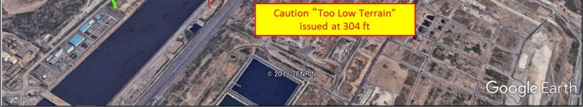
(2) Terrain Database of EGPWS
Man-made objects information in Japan contains only Tokyo Tower (Japan Broadcast Tower)
in terrain database of EGPWS of the Aircraft. Information pertinent to Tokyo Skytree Tower was
registered in versions after –460 (issued on February 28, 2011) and information pertinent to other
man-made objects in Japan was registered in terrain database versions after –484 (issued on March
16, 2017). Analysis of operational situations in the event of flying the same path with the EGPWS
updated to after –484 version obtained the result that warning “Obstacle Obstacle Pull-UP” was
enunciated at an altitude of 434 ft in reaction to the man-made objects of Tokyo Bayside Wind Power
Plant (“Tokyo Kazaguruma” (see Figure 7)) located ahead of the flight path.
- 19 -Figure 7: Flight track recorded in EGPWS
2.12.2 Dealings when EGPWS Alert is Enunciated
OM of the Company stipulates dealings described below when EGPWS alert is enunciated:
(excerpt)
8.3.5.3 Instructions
The P-i-C (PIC*34) ensures, using all available resources that adequate terrain clearance
is maintained.
(omitted)
When undue proximity to the ground is detected by any flight crew member or by a ground
proximity WARNING system, the PF ensures that corrective action is initiated
immediately to establish safe flight conditions.
2.13 Education and Training for Crew Members
The Airport is categorized as Aerodrome Category B (self-briefing by means programmed
instruction on the aerodrome concerned) by the Company, which requires crew members to study by
themselves various knowledge such as general knowledge, preferential runway for take-off and
landing, weather, operational procedures during the late-night and early morning hours and various
knowledge using the material of Operational Procedures at Tokyo International Airport (Haneda),
which the Company developed for its crew members, and training using simulator was not performed.
34 “PIC” is an abbreviation of Pilot in Command and denotes the person who undertakes tasks of a captain of an aircraft.
- 20 -3 ANALYSIS
3.1 Airman Competence Certificate and Aviation Medical Certificate
The PIC and the FO held both valid airman competence certificates and valid aviation medical
certificates.
3.2 Airworthiness Certificate
The Aircraft had a valid airworthiness certificate and had been maintained and inspected as
prescribed.
3.3 Relations to Meteorological Conditions
It is highly probable that meteorological conditions had no relation to the occurrence of the
serious incident.
3.4 History of the Flight
3.4.1 Prior to the Flight
As described in 2.1.2 (1), the PIC and the FO confirmed with NOTAM described in 2.8.4 that
runway A (runway 16R/34L) and runway D (runway 05/23) were closed at the scheduled arrival time
of the Aircraft, and grasped that runway B (runway 04/22) and runway C (Runway 16L/34R) were
available to use at the time of arrival; however, it is probable that they did not know that Runway
16L was preferentially used by the preferential runway procedure.
3.4.2 Flight until Commencing VOR A Approach (to DARKS)
As described in 2.1.2 (1) and (2), the PIC performed approach briefing assuming that landing
runway was Runway 22 from predicted wind before obtaining ATIS information for the Airport. It is
probable that the PIC instructed to re-input FMS after preparing the pertinent charts (Appended
Figure 2, 3 and 4) and performed briefing again, and the PIC and the FO confirmed the procedures
up to arrival at the Airport because the PIC confirmed that landing runway was 16L and type of
approach was VOR A approach after receipt of ATIS information “B”.
3.4.3 During the Flight in the Final Approach Path for VOR A Approach (from
DARKS to SAZAN)
As described in 2.1.2 (1), Landing gear lever was operated to the down position before reaching
SAZAN, Flaps were set to “30” for landing configuration and the Aircraft entered the level flight at
an altitude of 1,100 ft. It is probable that the flight up to that point was as planned by the PIC.
3.4.4 Circling Approach (from SAZAN until Entering Down-Wind Leg while Circling
to the Right)
The PIC stated that he commenced circling approach with turning right at a distance 4 DME
from Haneda VOR/DME as a reference after passing over SAZAN as described in 2.1.2 (1); however,
the reality was that the Aircraft commenced circling approach with turning right immediately after
- 21 -passing over SAZAN at 23:49:56. It is probable that the PIC commenced circling approach with
turning right relying on the view of Runway 16L to perform visual approach in circling approach;
however, it is somewhat likely that the PIC at that time did not confirm the point to commence the
circling approach and the positional relation between runway and the Aircraft by DME display on
ND. As described in 2.11, it is probable that the Aircraft could have flown inside the noise abatement
flight course if it commenced circling approach with turning right at the point of 4 DME from Haneda
VOR/DME. The PIC informed the FO, who had been the PM, that the PIC would commence circling
approach with turning right at 4DME from Haneda VOR / DME in advance during the approach
briefing in order for the FO to properly and appropriately perform the monitoring described in 2.10.1
at an early stage. If the image of the approach is shared, it is somewhat likely that the PIC could
have received support from the FO as appropriately with regard to the turning start point, the
positional relationship between the runway and the Aircraft, and the like.
It is highly probable that the width of the down-wind leg was widened (about 3.6 nm) in that
the point to commence circling approach with turning right went far away from runway.
3.4.5 Circling Approach (from Down-Wind Leg to Commencing Base Turn)
It is highly probable that approach guidance lights ((1) in Appended Figure 1), which were
thought to be ahead on the right of the Aircraft, was actually located ahead on the left due to the
widened width of the down-wind leg as described in 3.4.4. Because of that, as described in 2.1.2 (1)
and (2), it is probable that the PIC and the FO became aware, by seeing approach guidance lights
ahead on the left ((1) in Appended Figure 1), that the Aircraft was flying outside the noise abatement
flight course described in 2.8.3, and the PIC commenced the left turn as the base turn in an attempt
to fly inside the noise abatement flight course.
Besides, as described in 2.1.2 (1) and as shown in Appended Figure 1, the PIC entered the
down-wind leg and commenced the final descent for landing using VS mode of AP at 23:50:12. The
position of the Aircraft at that time was 4.6 nm away in direct distance from the point of 1 nm short
of 16L. So,it is highly probable that the timing to commence descending was too early. It is somewhat
likely that this was due to that the final descent for landing commenced by the PIC’s guess without
a clear picture for descent plan because of the wider width of the down-wind leg than he originally
planned. OM of the Company pertinent to circling approach described in 2.10.2 (1) stipulates “The
final descent shall be started no earlier than where it fits into a normal approach angle”. Although
an accurate comparison cannot be made due to difference in actual flight course and noise abatement
flight course, it is probable that an altitude of 1,100 ft should have been maintained in the down-
wind leg flight in order to land on Runway 16L at normal descent angle (3 o) as described in 2.11.
Besides, the PIC kept VS mode of AP after commencing descent until go-around; however, in
view of FCTM pertinent to circling approach described in 2.10.2 (2), it is probable that the PIC should
have disengaged AP and disconnected autothrottle at the time of commencing the final descent for
landing.
In view of the limitations pertinent to the use of AP stipulated in FCOM in 2.10.5, it is highly
probable that the PIC should have disengaged AP before reaching an altitude of 710 ft at the latest,
more than 50 ft below MDA, followed by manual operation during the descent. It is highly probable
that the FO should have advised the PIC to disengage AP when reaching the altitude through
monitoring the altitude of the Aircraft.
3.4.6 Circling Approach (from Base Turn to Go-Around)
- 22 -As described in 2.1.2 (1) and (2), the PIC and the FO performed call-out procedures when
reached 500 ft AFE in accordance with OM of the Company pertinent to stabilized approach
described in 2.10.3. The PIC and the FO continued approaching because the Aircraft was in landing
configuration at an appropriate speed and a descent rate, and Runway 16L was always visually
recognizable; however, as shown in Appended Figure 1, the distance from the point where the
Aircraft reached 500 ft AFE to the touchdown point on Runway 16L was as far away as 3.2 nm in
direct distance (depression angle of 1.5 o), and accordingly, it is highly probable that Runway 16L
was seen at a fairly shallow angle from the cockpit. It is probable that the Aircraft could have
executed a go-around by judging that it deviated the stabilized approach criteria described in 2.10.3
at the point of reaching 500 ft AFE if the PIC and the FO recognized at that time that the descent
path for landing on Runway 16L was too low to be appropriate.
As described in 2.1.2 (2), it is probable that the PIC concentrated on flying inside the noise
abatement flight course and letting the Aircraft to fit into the final leg of Runway 16L, and continued
descent changing the setting of AP descent rate between 200 and 500 fpm without paying an
appropriate caution for the actual descent path. It is probable that this caused an excessive descent
rate of the Aircraft leading to deviate from desirable flight path.
Furthermore, it is probable that the PIC temporarily became less attentive to visual
recognition of Runway 16L from the time of passing over 500 ft AFE until he was advised by Tokyo
Tower, “Your altitude is too low, confirm, do you have. Runway 16L insight?” because he was
concentrating on modifying lateral flight path. Refering to OM of the Company pertinent to circling
approach described in 2.10 (1), it is probable that the PIC should have grasped the positional relation
with runway and the flight path of his own aircraft in circling approach by keeping visually
recognizing Runway 16L or approach guidance lights used for landing throughout the entire path.
As described in 2.1.2 (2), the FO monitored on ND and pointed out to the PIC the lateral flight
path of the Aircraft in the horizontal direction; however, it is probable that the FO was not aware
that the descent path was too low because he was concentrating on monitoring the lateral flight path.
As stipulated in OM of the Company pertinent to task sharing described in 2.10.4, it is probable that
the FO should have given the PIC as PF necessary advice by correctly grasping the flight path of his
own aircraft through monitoring all instruments based on the recognition of his roles as PM.
As described in 2.1.2 (1) and (2), when advised by Tokyo Tower, “Your altitude is too low, confirm,
do you have Runway 16L insight?” it is probable that the PIC was unable to grasp the position of
Runway 16L because approach light beacon ((4) in Appended Figure 1) was not visually recognizable
due to its mixing with the lights of the container piers ((5) in Appended Figure 1) located ahead on
the left and the lights of the town.
It is probable that, immediately after the PIC told the FO, “Negative ” and the FO conveyed it
to Tokyo Tower, EGPWS caution “TOO LOW TERRAIN” was enunciated, and the PIC judged that
the Aircraft came too close to the ground surface and instantaneously executed a go-around to avoid
collision with it in accordance with OM of the Company described in 2.12.2.
3.5 AIP Chart for Noise Abatement Flight Course at the Time of Occurrence of the
Serious Incident
As described in 2.8.3, noise abatement flight course is published in relation to the circling
approach course at the Airport, and aircrafts are required to fly along or inside the flight course.
However, it is somewhat likely that visual selections of the flight course were easy to vary depending
on crew members who selected the flight course because the AIP chart (see Appended Figure 9) for
- 23 -You can also read