MODE SWITCHING TUBE AMPLIFIER - Mode Switching Tube Guitar Amplifier OWNER'S MANUAL
←
→
Page content transcription
If your browser does not render page correctly, please read the page content below

MODE SWITCHING TUBE AMPLIFIER
       Mode Switching Tube Guitar Amplifier
                      OWNER’S MANUAL
Important Safety Instructions
hotwire VT12
1. Read these instructions. 13. Unplug this apparatus during lightning storms or when unused for long
2. Keep these instructions. periods of time.
3. Heed all warnings. 14. Refer all servicing to qualified service personnel. Servicing is required
when the apparatus has been damaged in any way, such as power-
4. Follow all instructions. supply cord or plug is damaged, liquid has been spilled or objects have
fallen into the apparatus, the apparatus has been exposed to rain or
5. Do not use this apparatus near water.
moisture, does not operate normally, or has been dropped.
6. Clean only with dry cloth.
15. This apparatus shall not be exposed to dripping or splashing, and no
7. Do not block any ventilation openings. Install in accordance with the object filled with liquids, such as vases, shall be placed on the apparatus.
manufacturer’s instructions.
16. This apparatus has been designed with Class-I construction and must
8. Do not install near any heat sources such as radiators, heat registers, be connected to a mains socket outlet with a protective earthing con-
stoves, or other apparatus (including amplifiers) that produce heat. nection (the third grounding prong).
9. Do not defeat the safety purpose of the polarized or grounding-type 17. This apparatus has been equipped with a single-pole, rocker-style AC
plug. A polarized plug has two blades with one wider than the other. mains power switch. This switch is located on the front panel and
A grounding-type plug has two blades and a third grounding prong. should remain readily accessible to the user.
The wide blade or the third prong are provided for your safety. If the
18. This apparatus does not exceed the Class A/Class B (whichever is
provided plug does not fit into your outlet, consult an electrician for
applicable) limits for radio noise emissions from digital apparatus as
replacement of the obsolete outlet.
set out in the radio interference regulations of the Canadian Department
10. Protect the power cord from being walked on or pinched particularly at of Communications.
plugs, convenience receptacles, and the point where they exit from the
ATTENTION — Le présent appareil numérique n’émet pas de bruits
apparatus.
radioélectriques dépassant las limites applicables aux appareils numériques de
11. Only use attachments/accessories specified by the manufacturer. class A/de class B (selon le cas) prescrites dans le réglement sur le brouillage
radioélectrique édicté par les ministere des communications du Canada.
12. Use only with a cart, stand, tripod, bracket, or table specified by the
manufacturer, or sold with the apparatus. When a cart is used, use 19. Exposure to extremely high noise levels may cause permanent hearing
caution when moving the cart/apparatus combination to avoid injury loss. Individuals vary considerably in susceptibility to noise-induced
from tip-over. hearing loss, but nearly everyone will lose some hearing if exposed to
sufficiently intense noise for a period of time. The U.S. Government’s
PORTABLE CART WARNING Occupational Safety and Health Administration (OSHA) has specified
the permissible noise level exposures shown in the following chart.
Carts and stands - The
Component should be used According to OSHA, any exposure in excess of these permissible limits
only with a cart or stand could result in some hearing loss. To ensure against potentially danger-
that is recommended by
the manufacturer. ous exposure to high sound pressure levels, it is recommended that all
A Component and cart persons exposed to equipment capable of producing high sound pres-
combination should be sure levels use hearing protectors while the equipment is in operation.
moved with care. Quick Ear plugs or protectors in the ear canals or over the ears must be worn
stops, excessive force, and
uneven surfaces may cause
when operating the equipment in order to prevent permanent hearing
the Component and cart loss if exposure is in excess of the limits set forth here.
combination to overturn.
Duration Per Day Sound Level dBA, Typical
CAUTION AVIS In Hours Slow Response Example
RISK OF ELECTRIC SHOCK
DO NOT OPEN 8 90 Duo in small club
RISQUE DE CHOC ELECTRIQUE 6 92
NE PAS OUVRIR
4 95 Subway Train
CAUTION: TO REDUCE THE RISK OF ELECTRIC SHOCK
DO NOT REMOVE COVER (OR BACK) 3 97
NO USER-SERVICEABLE PARTS INSIDE
REFER SERVICING TO QUALIFIED PERSONNEL 2 100 Very loud classical music
ATTENTION: POUR EVITER LES RISQUES DE CHOC 1.5 102
ELECTRIQUE, NE PAS ENLEVER LE COUVERCLE. AUCUN
ENTRETIEN DE PIECES INTERIEURES PAR L'USAGER. CONFIER 1 105 Tami screaming at Adrian about deadlines
L'ENTRETIEN AU PERSONNEL QUALIFIE.
AVIS: POUR EVITER LES RISQUES D'INCENDIE OU 0.5 110
D'ELECTROCUTION, N'EXPOSEZ PAS CET ARTICLE
A LA PLUIE OU A L'HUMIDITE 0.25 or less 115 Loudest parts at a rock concert
The lightning flash with arrowhead symbol within an equilateral
triangle is intended to alert the user to the presence of uninsulated
WARNING — To reduce the risk of fire or
"dangerous voltage" within the product's enclosure, that may be
of sufficient magnitude to constitute a risk of electric shock to persons.
Le symbole éclair avec point de flèche à l'intérieur d'un triangle
équilatéral est utilisé pour alerter l'utilisateur de la présence à
l'intérieur du coffret de "voltage dangereux" non isolé d'ampleur electric shock, do not expose this apparatus
to rain or moisture.
suffisante pour constituer un risque d'éléctrocution.
The exclamation point within an equilateral triangle is intended to
alert the user of the presence of important operating and maintenance
(servicing) instructions in the literature accompanying the appliance.
Le point d'exclamation à l'intérieur d'un triangle équilatéral est
employé pour alerter les utilisateurs de la présence d'instructions
importantes pour le fonctionnement et l'entretien (service) dans le
livret d'instruction accompagnant l'appareil.
hotwire VT12
Table of Contents

                                                                                                                                                                                                             Owner’s Manual
Introduction.................................................................................................................................. 5
Getting Started............................................................................................................................7
VT12 Features................................................................................................................................9
     Input Stage and Hotwire Section.......................................................................................................................................9
       1. INPUT..................................................................................................................................................................................9
       2. SIG ......................................................................................................................................................................................9
       3. CLIP......................................................................................................................................................................................9
       4. GAIN ..................................................................................................................................................................................9
       5. MANUAL............................................................................................................................................................................9
       6. BRIGHT...............................................................................................................................................................................9
       7. MODE Switch....................................................................................................................................................................9
       8. DRIVE.................................................................................................................................................................................10
       9. VOLUME............................................................................................................................................................................10
     EQ and Effects Section.........................................................................................................................................................10
       10. USA/UK..........................................................................................................................................................................10
       11. BASS...................................................................................................................................................................................10
       12. MIDDLE............................................................................................................................................................................10
       13. TREBLE..............................................................................................................................................................................10
       14. PRESENCE.........................................................................................................................................................................11
       15. EFX......................................................................................................................................................................................11
       16. MODULATION................................................................................................................................................................11
       17. DELAY...............................................................................................................................................................................12
       19. REVERB.............................................................................................................................................................................13
       20. MASTER VOLUME........................................................................................................................................................13
     Display and Channel Section..............................................................................................................................................13
       21. Display.............................................................................................................................................................................13
       22. Select/Adjust Knob.....................................................................................................................................................13
       23. CLEAN..............................................................................................................................................................................13
       24. CRUNCH..........................................................................................................................................................................13
       25. OVERDRIVE....................................................................................................................................................................13
       26. LEAD.................................................................................................................................................................................14
       27. EXIT...................................................................................................................................................................................14
       28. BUZZ................................................................................................................................................................................14
       29. NOTCH.............................................................................................................................................................................14
       30. SPEAKER..........................................................................................................................................................................14

                                  Don’t forget to visit our website at www.mackie.com for more
                                       information about this and other Mackie products.

Part No. SW0658 Rev. A 02/08                                                                                                                                                                             R

©2008 LOUD Technologies Inc. All Rights Reserved.

Owner’s Manual 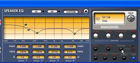
31. SAVE..................................................................................................................................................................................14
hotwire VT12
                       32. MIC...................................................................................................................................................................................15
                       33. COMP...............................................................................................................................................................................15
                       34. CLICK................................................................................................................................................................................15
                       35. TUNER..............................................................................................................................................................................15
                       36. TOOLS.............................................................................................................................................................................16
                       37. OUTPUT POWER...........................................................................................................................................................16
                       38. MAINS Switch...............................................................................................................................................................16
                    Rear Panel................................................................................................................................................................................17
                     39. AC Power Receptacle..................................................................................................................................................17
                     40. USB..................................................................................................................................................................................17
                     41. PEDAL...............................................................................................................................................................................17
                     42. EXTERNAL SPEAKER....................................................................................................................................................17
                     43. PHONES OUT.................................................................................................................................................................17
                     44. PHONES LEVEL..............................................................................................................................................................17
                     45. LINE OUTPUT LEFT/RIGHT.......................................................................................................................................17
                     46. LINE INPUT LEFT/RIGHT...........................................................................................................................................18
                     47. LINE INPUT GAIN..........................................................................................................................................................18
                     48. INSERT LOOP SEND/RETURN..................................................................................................................................18
                     49. MIC INPUT......................................................................................................................................................................18
                     50. MIC INPUT GAIN..........................................................................................................................................................18
               Factory Presets........................................................................................................................... 18
               Saving Your Own........................................................................................................................ 19
               VT12 Control Panel....................................................................................................................20
                    Installing the Software........................................................................................................................................................20
                      Computer Requirements.................................................................................................................................................20
                      Installing the VT12 Control Panel..................................................................................................................................20
                    Controls....................................................................................................................................................................................21
                      Installing Tracktion...........................................................................................................................................................24
               Appendix A: Service Information..........................................................................................25
                    Troubleshooting.................................................................................................................................................................... 25
                    Repair....................................................................................................................................................................................... 25
               Appendix B: Connections........................................................................................................26
               Appendix C: Technical Info.....................................................................................................28
                    VT12 Specifications...............................................................................................................................................................28
                    VT12 Block Diagram..............................................................................................................................................................30
               VT12 Limited Warranty.............................................................................................................31

                    hotwire VT12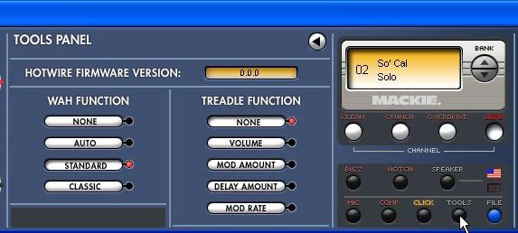
Introduction

                                                                                                                            Owner’s Manual
  Thank you for choosing the Mackie Hotwire VT12                 A USB connection is provided on the rear panel for
professional guitar amplifier, the world’s first Class A/A-B   connecting to your computer. You can install the VT12
mode-switching tube guitar amplifier for live performance      control panel application on your computer (PC or Ma-
and studio recording.                                          cintosh), which gives you access to even more editing of
                                                               user modes, presets, speaker EQ curves, and effects set-
  The Hotwire VT12 is a single 12" combo amplifier             tings. It also allows you to stream audio from the VT12
combining extremely high power with a remarkably light-        to your computer’s DAW application for recording.
weight, compact package offering players maximum flex-
ibility of features with authentic vacuum tube tonality.         An optional foot pedal board is available (PB-1) for
                                                               switching channels, changing banks, wah, volume, and
  This unique guitar amplifier was created by Greg             expression foot control, and controlling the VT12’s ten-
Mackie over a period of several years of meticulous            second onboard loop recorder, with unlimited overdubbing
research and design, using proven techniques (okay,            capability. A simpler four-button footswitch (PB-4) is
and some trial and error) to fine tune the circuitry and       also available that can switch among the four channels.
obtain the sounds for each mode. Other guitar amp
manufacturers use DSP to “model” the sound of various             The features built into the VT12 go on and on, so we’ve
vacuum tube amplifiers. Greg thought, “Why use DSP             listed them below to provide a quick overview of all of
to model tubes when we can simply put tubes in the             them. Be sure to read the “Getting Started” section next.
amp?” So the VT12 has two 12AX7A tubes in the preamp           It will help you quickly understand how the VT12 works,
section, which can be literally rewired, or “Hotwired,” to     and have you enjoying your new guitar amp in no time.
create different tube circuits by using the Mode control.
The VT12 comes with 12 Factory Modes, with the capa-
bility to modify and store them, and recall the original
Factory Modes at any time using the VT12’s control             VT12 Features
panel application (more on that later).                        •   Authentic tube amplifier tone, ranging from Hi-Fi
  These modes serve as the basis to create presets,                clean sounds to full-on high gain distortions.
which can also be stored in memory. You can create             •   Fully-configurable dual 12AX7A vacuum tube
up to 96 presets (24 banks of 4 channels each: Clean,              circuitry with 12 factory wiring modes (including
Crunch, Overdrive, and Lead). The distortion sounds                LINE, ACOUSTIC, HI FI, JAZZ, BLUES, CLASS A,
are created by the tube circuitry for that genuine tube            UK I, UK II, USA I, USA II, HI GAIN I, and HI GAIN
overdrive sound.                                                   II), which can be modified for your own personal
  A 1.35" compression driver is included for high-                 preference.
frequency enhancement of the Line, Acoustic, and Hi-Fi         •   High power: 120 W main amplifier, + 30 W com-
modes. Thus, the VT12 can become a full-range system               pression driver amplifier, + 30 W external speaker
for acoustic guitars, keyboards, microphones, and other            amplifier.
sources. There is a microphone input on the rear panel,
so as an example you could sing through the micro-             •   Extremely light weight: at less than 25 lbs., the
phone in full-range mode while the guitar is routed                VT12 is roughly half the weight of many typical
through the tubes and limited to the 12” speaker.                  single 12" combo amplifiers.
  Of course, standard tone stack controls are provided;        •   Four-band tone stack (Bass, Middle, Treble, and
Bass, Middle, and Treble, along with a Presence control.           Presence), with user-selectable USA and UK tone
Standard effects controls are also included; Modulation,           stack types.
Delay, and Reverb, with numerous types to choose from
                                                               •   32-bit onboard digital effects, including modulation
for each effect.
                                                                   (chorus, flanger, phaser, tremolo, modulated delay,
  There is a unique Output Power control, with set-                and rotary speaker), delay (mono delay, tape echo,
tings from 120 watts down to 1 watt. Each click of the             multitap delay), and reverb (room, hall, plate,
control reduces the output power by 3 dB (or one-half),            spring short, and spring long).
Most guitar players like the sound of their amp at high
                                                               •   2 x 8 character amber-backlit LCD display.
volumes, but can’t always play it that loud (rehearsal,
small clubs, etc.). The Output Power control allows you        •   Storage capability for 96 presets, arranged in banks
to retain the soft overload and distortion characteristics         of Clean, Crunch, Overdrive, and Lead channels.
of the amplifier without the high volume.
                                                               •   One-button Buzz feature, for eliminating noise due
                                                                   single-coil pickups or other noisy input sources.

Owner’s Manual 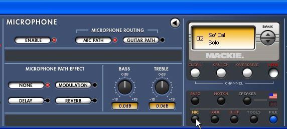
•   Notch filter, for reducing feedback on acoustic          HOW TO USE THIS MANUAL
hotwire VT12
                   instrument sources.
                                                                              We know that many of you can’t wait to get your new
               •   Front-panel selectable USA           and UK              guitar amplifier working, and you’re probably not going
                   speaker emulations.                                      to read the manual first (sigh!). So the first section after
                                                                            this introduction is a Quick-Start Guide called “Getting
               •   Manual mode, for “what-you-see-is-what-you-get”
                                                                            Started” to help you get the VT12 set up fast so you can
                   (basic guitar amp) operation.
                                                                            start using it right away.
               •   Rear-panel microphone input, with user-selectable
                                                                               Then, when you have time, read the Features Descrip-
                   routing options.
                                                                            tion section. This describes every knob, button, and
               •   Onboard compressor/limiter.                              connection point on the VT12, as well as the software
                                                                            control panel application settings and controls.
               •   Click (metronome) function, with variable tempo,
                   sample type, and volume.                                    Throughout this section you’ll find illustrations with
                                                                            each feature numbered. If you want to know more about
               •   Onboard chromatic strobe tuner.                          a feature, simply locate it on the appropriate illustra-
               •   Tools menu, allowing access to utility functions.        tion, notice the number attached to it, and find that
                                                                            number in the nearby paragraphs.
               •   Output Power control, providing fully-cranked
                   amplifier tones at low volumes.                                              This icon marks information that is
                                                                                                critically important or unique to the
               •   A 12" custom-voiced speaker, with neodymium mag-                             VT12. For your own good, read them
                   net structure for reduced weight.                                            and remember them. They will be on
               •   A 1.35" Celestion neodymium compression driver                               the final test.
                   with custom waveguide.                                                       This icon leads you to in-depth
               •   Insert loop, for inserting external effects/signal                           explanations of features and practi-
                   processors.                                                                  cal tips. While not mandatory, they
                                                                                                usually have some valuable nugget of
               •   Stereo line inputs, for jamming along with a CD or                           information.
                   MP3 player.
               •   Cabinet-emulated stereo line outputs.                    A PLUG FOR THE CONNECTOR SECTION
               •   Stereo headphone output.                                   Appendix C is a section on connectors: XLR connec-
                                                                            tors, balanced connectors, unbalanced connectors, and
               •   External speaker jack, for connecting the optional       the insert connectors used on the VT12.
                   EX12 extension speaker cabinet.
               •   Pedal jack, for connecting optional PB-1 and PB-4        More resources on our website at
                   pedal boards.
                                                                            www.mackie.com
               •   USB jack — provides streaming audio to PC (cabi-            Visit our website and click “Support.” There you will
                   net emulated) for recording applications, and al-        find links to the Glossary of Terms (brief explanations
                   lows for deep editing, preset archiving, live control,   of many pro audio terms), Frequently Asked Questions
                   and firmware upgrade functions.                          (FAQs), and our forums (our online help community).
               •   Seven-ply Italian poplar cabinet construction, for         Now, let’s get started!
                   warm tone and light weight.
               •   Universal switching power supply.
               •   Includes Tracktion Music Production Software for
                   digital audio recording.

                  hotwire VT12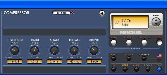
Getting Started
                                                                     4. Turn up the VOLUME and DRIVE controls about

                                                                                                                                   Owner’s Manual
                                                                        halfway (12 o’clock position). SLOWLY turn up the
                                                                        MASTER VOLUME control while strumming your
                                                                        guitar until you hear your guitar, and set it for a
READ THIS PAGE!!                                                        comfortable listening level.

                       Even if you’re one of those people               Now that you are getting sound through your ampli-
                       who never reads manuals, all we ask           fier, let’s talk about the Hotwire section. The input stage
                       is that you read this page now before         of the VT12 is comprised of two 12AX7A vacuum tubes,
                       you begin using the VT12. You’ll be           with two gain stages per tube (it’s a dual-triode vacuum
                       glad you did!                                 tube for those of you interested in such things), for a
                                                                     total of four vacuum tube gain stages.
  The Hotwire VT12 may seem daunting at first with all
the knobs and buttons on the top panel. However, once                   The MODE switch is used to rewire the configura-
you understand the concept and the signal-flow of the                tion of these four gain stages and, along with carefully
amplifier, you will see that it operates very much like              applied EQ voicing, create the different sounds that
any other guitar amplifier. It just has more features and            represent the many styles of guitar amplifiers that have
options to spark your creativity than any other guitar               been used throughout the years.
amp you’ve ever seen.                                                   The following screenshot from the VT12 PC applica-
                                                                     tion shows a graphical representation of the UKI Mode.
Input Stage and Hotwire Section
                        USA I
             CLASS A            USA II

          BLUES          O DE        UK I
                       M                                       EQ

          JAZZ                           UK II

           HI-FI                     HI GAIN I

          ACOUSTIC               HI GAIN II                                 TYPE
                                                                            STYLE             TYPE              TYPE
                         LINE

             MANUAL             BRIGHT                                 As you switch through the various modes, the switch-
                                                               EFX   es in the above tube wiring diagram change positions to
                                                                     represent how the tubes are rewired. In addition, EQ is
                          SIG                                        applied before and after the tube preamp stage.
              INPUT              GAIN
                                                                       There are two more controls to discuss in relation
                                                                     to the input stage: the DRIVE control and VOLUME
1. Turn down the VOLUME, DRIVE and MASTER VOL-                       control (we’ll discuss the MANUAL button on page 9;
   UME controls, and set the MODE control to JAZZ.                   the BRIGHT button simply adds a fixed mid-to-high-fre-
                                                                     quency boost to the signal).
2. Plug your guitar into the INPUT jack and turn the
   POWER switch on.                                                    The DRIVE control provides additional gain before the
                                                                     tube stage. You can use this to adjust the amount of ana-
3. Set the GAIN control to NORMAL and strum your
                                                                     log tube distortion you can hear for the particular mode
   guitar. If your guitar has its own volume control(s),
                                                                     you have selected. The more DRIVE, the more distortion.
   adjust them to where you normally set them when
   you play. You should see the yellow SIG LED light,                  The VOLUME control adjusts the signal level after the
   indicating that the VT12 sees a signal coming from                tube stage and the EQ section (described next). With high
   your guitar. If the SIG LED doesn’t light, try turning            drive levels and high gain modes, you may need to turn the
   up the GAIN control or the volume control(s) on                   VOLUME control down to compensate. On the other hand,
   your guitar. If the CLIP LED lights continuously or               with low drive levels and low gain modes, you can turn the
   frequently, turn down the GAIN control or the volume              VOLUME control up more for a cleaner sound.
   control(s) on your guitar (it’s okay if the CLIP LED
   lights occasionally).

Owner’s Manual 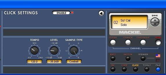
EQ and Effects Sections Display and Channel Section
hotwire VT12
MODE SWITCHING TUBE AMPLIFIER
02 Silver
BY
USA II EQ
Surfer
MODE SWITCHING TUBE AMPLIFIER
02 Silver
UK I BY
EQ
Surfer
UK II
NI CLEAN CRUNCH OVERDRIVE LEAD
MAINS
TYPE
STYLE TYPE TYPE
HI GAIN I CLEAN CRUNCH OVERDRIVE
EXIT
LEAD 8 16
MAINS
TYPE TYPE TYPE 4 30
HI GAIN II STYLE
ATT
CHANNEL EXIT 8 16
BUZZ NOTCH SPEAKER 2 W 4 60 30
S
ATT
CHANNEL
SAVE
EFX
BUZZ NOTCH SPEAKER 1 2 W 120 60
S
BRIGHT
SAVE
MIC COMP CLICK TUNER TOOLS
EFX
1 120
MIC COMP CLICK TUNER TOOLS
GAIN
The EQ section contains the four EQ controls: BASS,
MIDDLE, TREBLE, and PRESENCE. These controls The four channel buttons, CLEAN, CRUNCH, OVER-
come after the tube stage, and provide the opportunity DRIVE, and LEAD, give you access to four preset sounds
to adjust the overall sound of the particular mode you stored within the current bank.
have selected.
There are 24 banks of four stored
The EQ section also has a USA/UK tone stack switch. presets, one for each channel. Change
This changes the characteristics of the EQ to resemble banks by turning the Select/Adjust
either USA or UK style tone controls. knob next to the display, then press a
channel button to recall the preset for
The Effects section contains Modulation, Delay, and
that bank and channel.
Reverb controls. You can switch the Effects section on
and off with the EFX button next to the MODULATION A preset stores the following settings: Mode, Drive,
control. Volume, EQ, Bass, Middle, Treble, Presence, Modulation,
Delay, Reverb, and Compressor.
Each effect has a number of types you can select by
pressing the TYPE button just above the MODULATION, You can create your own preset and save it to a bank
DELAY, and REVERB controls. The currently selected and channel using the SAVE button. Refer to page 14 for
type appears in the display. Rotate the Select/Adjust more details on how to do this.
knob to change the type of the effect, and press the
There are several miscellaneous buttons in this sec-
Select/Adjust knob to cycle through the parameters for
tion, including EXIT, BUZZ, NOTCH, SPEAKER, SAVE,
each effect.
MIC, COMP, CLICK, TUNER, and TOOLS. These are
described in more detail in the “Display and Channel”
Select/Adjust Knob section beginning on page 13.
Finally, the OUTPUT POWER switch allows you to
reduce the amplifier power in 3 dB increments (halving
02
the power reduces it by 3 dB). As the output power is
Silver reduced, so is the overall volume and the point at which
Surfer the amplifier overloads. This allows you to get a “loud”
(i.e., overdrive) sound without having the amplifier
playing loud. Good for practicing and keeping peace
with your neighbors.
The MASTER VOLUME control is also in this section.
It controls the amount of signal that is sent to the power That’s it for the Getting Started section. Hopefully,
amplifier section, after the EQ and Effects sections. Use this has provided enough information to get you well on
this to control the overall volume of the amplifier. your way to enjoying your new Hotwire VT12. The next
section, VT12 Features, goes into more detail describ-
ing every input, output, knob, and button on the VT12.
After that, there is a section on the VT12 Control Panel,
which describes how to install the VT12 Control Panel
application on your computer. This provides access to
even more editing and control features than you have
available on the top panel of the VT12.
hotwire VT12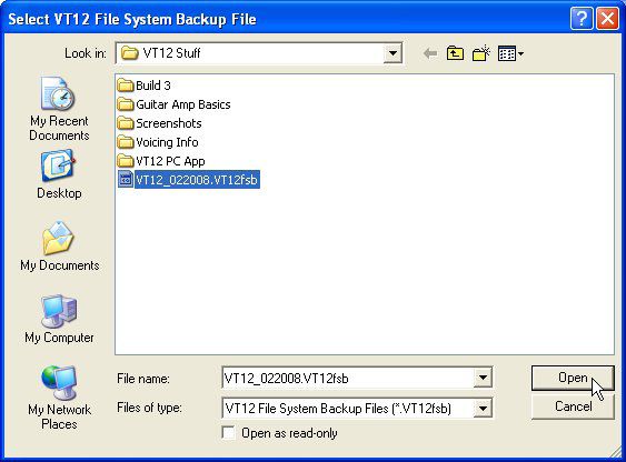
VT12 Features

                                                                                                                           Owner’s Manual
                                                               5. MANUAL
Input Stage and Hotwire Section                                   Push this button to activate manual mode. When
                                                               manual mode is active, the LED next to the button
                                                               lights and the display goes blank. All of the channel
1. INPUT                                                       presets and effects are bypassed by default when in
                                                               manual mode, so only the MODE switch and EQ controls
   This is where you plug in your guitar or other instru-      are active. Use manual mode to simplify the operation of
ment. It is a 1/4" TS connector that accepts an unbal-         the VT12 for basic guitar amp operation.
anced instrument-level input signal from a high-imped-
                                                                 You can reactivate the effects by pressing the EFX
ance instrument like a guitar or a line-level signal from
                                                               [15] button. The previous effects settings are activated.
a low-impedance source (LINE mode [7]).
                                                               You cannot change the effects settings from the VT12
                                                               top panel, but you can from the VT12 Control Panel on
2. SIG                                                         your computer.

  This LED indicates when signal is present at the input
jack. It senses the signal after the input GAIN control,       6. BRIGHT
but before the DRIVE and VOLUME controls.
                                                                 This button applies a fixed mid/high frequency boost
                                                               to the input signal. When Bright is activated, the LED
3. CLIP                                                        next to the button lights.

   The CLIP LED lights when the input preamp reaches
its maximum output and is on the verge of clipping. It’s       7. MODE Switch
okay for the CLIP LED to blink occasionally, but if it is
                                                                 Use the Mode switch to select among 12 different am-
blinking frequently or continuously, turn down the GAIN
                                                               plifier modes, emulating various classic guitar amplifier
control [4] or the volume control on your instrument.
                                                               sounds. As described in the “Getting Started” section,
                                                               the various sounds are created by “hotwiring” the tube
4. GAIN                                                        gain stages into different configurations and levels of
                                                               gain, along with applying selected EQ voicings.
  The GAIN controls adjust the input sensitivity of the
instrument input. This allows the signal from the outside        Note: You can modify and overwrite a factory mode
world to be adjusted to optimal internal operating levels.     setting using the VT12 Control Panel’s FILE button (see
                                                               page 22 for more info).
   Set the GAIN control to the NORMAL position (12
o’clock). The SIG LED should stay lit while you are play-        The VT12 has a 12" speaker as well as a 1.35" com-
ing your instrument. If the SIG LED doesn’t light or blinks    pression driver. The compression driver and 12" speaker
occasionally, turn the GAIN control up. It’s okay if the       combination is used for the microphone input and the
CLIP LED blinks occasionally, but if it blinks frequently or   Line, Acoustic, and Hi-Fi settings on the Mode switch
lights continuously, turn the GAIN control down.               and provides a full-range output. The remaining settings
                                                               on the Mode switch only use the 12" speaker.

                      USA I
           CLASS A            USA II

                                                                                                                                            02
        BLUES          O DE        UK I
                     M                                EQ

       JAZZ                            UK II

         HI-FI                     HI GAIN I                                                                                     CLEAN      CRU

        ACOUSTIC               HI GAIN II                      TYPE
                                                               STYLE           TYPE            TYPE
                      LINE

                                                                                                                                  BUZZ      NO
           MANUAL             BRIGHT

                                                     EFX

                                                                                                                                  MIC        C

                       SIG

            INPUT              GAIN

Owner’s Manual 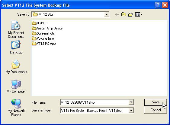
The following table provides a brief description of             control down to compensate. On the other hand, with low
hotwire VT12
               each of the Mode settings:                                        drive levels and low gain modes, you can turn the VOLUME
                                                                                 control up more for a cleaner sound.
                LINE                 Works like a standard line input and
                                     provides a clean signal for keyboards
                                     and other line-level sources.
                ACOUSTIC             Provides a voicing optimized for acous-     EQ and Effects Section
                                     tic electric and hybrid guitars.
                HI-FI                Full-range clean sound for electric         10. USA/UK
                                     guitar or keyboard.
                JAZZ                 Warm, dark, and clean sound for jazz          The EQ section has a USA/UK tone stack switch. This
                                     guitar.                                     changes the characteristics of the EQ to resemble either
                BLUES                Brighter sound with a bit of grit, de-      USA or UK style tone controls. The UK setting has a bit
                                     signed to accentuate touch sensitivity.     more midrange presence. Experiment to find the setting
                                                                                 that you like best for a particular riff or song.
                CLASS A              Pure clean tone ranging to ragged
                                     overdrive.
                USA I                Late-50s “tweed” sound.
                                                                                 11. BASS
                USA II               Early 60s “black face” sound.                 Use this to adjust the output level of the low frequen-
                UK I                 Classic British rock sound.                 cies of the selected channel. The adjustment range and
                                                                                 frequency is determined by the USA/UK button.
                UK II                High gain British rock sound.
                HI GAIN I            West coast high gain sound.
                HI GAIN II           Modern metal sound.
                                                                                 12. MIDDLE
                                                                                   Use this to adjust the output level of the mid frequen-
                                                                                 cies of the selected channel. The adjustment range and
                                                                                 frequency is determined by the USA/UK button.
               8. DRIVE
                 The Drive control adjusts the amount of gain within             13. TREBLE
               each amplifier mode, just before the tube stage. The
               higher the Drive control setting, the more overdrive                Use this to adjust the output level of the high frequen-
               sound you can achieve.                                            cies. The adjustment range and frequency is determined
                                                                                 by the USA/UK button.

               9. VOLUME
                 The Volume control provides the final overall gain for
               the signal from the preamp tube stage of the amplifier,
               after the Drive and EQ controls. With high drive levels
               and high gain modes, you may need to turn the VOLUME

                                       USA I
                           CLASS A             USA II

                                                                                                                                                      02
                         BLUES         O DE         UK I
                                     M                                     EQ

                        JAZZ                            UK II

                         HI-FI                      HI GAIN I                                                                                 CLEAN   CR

                         ACOUSTIC               HI GAIN II                        TYPE
                                                                                  STYLE           TYPE            TYPE
                                        LINE

                                                                                                                                              BUZZ    N
                           MANUAL              BRIGHT

                                                                           EFX

                                                                                                                                               MIC     C

                                         SIG

                            INPUT               GAIN

       10          hotwire VT12
14. PRESENCE Flanger
Owner’s Manual
The flange effect is very similar to the chorus effect,
Use this to adjust the overall brightness and punch of with Depth and Rate controls that operate as described
the output signal. The adjustment range is determined for the chorus effect. In addition, it also has a Feedback
by the USA/UK button. control (described below). A flanger typically has a short
depth time, which creates the characteristic “whooshing”
15. EFX sound often used to describe the flange sound.
Feedback: This controls the amount of the flanged
This button toggles all the effects on and off simulta-
signal that is routed back to the input of the flanger.
neously. When the effects are active, the LED above the
This changes the sound of the flange effect by adding
EFX button lights.
even more comb filtering to the signal. It ranges from 0%
HPF Freq: Each of the following effects has a high- to 100% in 1% steps.
pass filter with an adjustable frequency control. This
Phaser
determines the low-frequency cutoff of the filter, with a
range from 20 Hz to 20 kHz. A phaser is similar to a flanger, except that instead of
using delay to create the effect it uses a filter to alter
16. MODULATION the phase response of the “phased” signal, which is
mixed back into the original signal. It has the same con-
This control adjusts the amount of the currently trols as the flanger, except instead of a feedback control,
selected modulation effect that is mixed into the input it has a center control.
signal. Press the TYPE button above the Modulation Center: This control adjusts the center frequency of
control to view the currently selected modulation effect the filter, which is where the “notch” occurs in the comb
in the display. Rotate the Select/Adjust knob [22] next filtering. It ranges from 20 Hz to 20 kHz in variable steps.
to the display to change the modulation effect.
Tremolo
Chorus
The tremolo guitar effect has been around a long
The chorus effect simulates the sound of more than time, and is simply described as amplitude modulation,
one instrument playing the same passage. When two or cyclic change in volume. The tremolo effect has two
people play the same part in unison, they are never parameters you can adjust, rate and waveform.
exactly the same, so the chorus effect “modulates” the
timing and pitch of the “chorused” signal. Rate: This adjusts the rate at which the amplitude of
the signal is modulated, ranging from 0.08 Hz to 8 Hz in
Press the Select/Adjust knob to modify the following 0.01 Hz steps.
parameters for the chorus effect:
Waveform: This changes the character of the ampli-
Depth: The depth control adjusts how much the delay tude modulation by affecting how the volume changes
of the chorused signal changes over time by the Rate the signal. You can select from Sine, Hypersine, Square,
control (see next). The Depth control also affects the Triangle, and SawTooth.
pitch of the chorused signal; the more depth that is
applied, the more pitch modulation. This control has a Rotary
range from 0 ms to 10 ms in 0.1 ms steps.
The rotary effect simulates the sound of a rotary
Rate: This control adjusts the rate at which the delay speaker, similar to the famous Leslie speaker sound. It
applied to the chorused signal varies, ranging from 0.08 Hz is similar to the tremolo sound, but includes the Doppler
to 8 Hz in 0.01 Hz steps. effect as well (the Doppler effect is the apparent change
in frequency as a sound approaches or recedes). There
Voicing: There are three voice settings available; Mono, are two rotary speeds you can program, a low speed and
Stereo1, and Stereo2. The stereo settings are more obvi- a high speed. If you have the PB1 footpedal, you can use
ous when listening to headphones, stereo line outputs, or the pedal to change between the low speed and the high
recording via the USB connection. Normally, you will use speed. Otherwise, you can select whether you use the low
the Mono setting when listening through the amp. speed or the high speed using the Select/Adjust knob.
• Mono — the left and right channels are the same. Low Speed: This sets the speed at which the speaker
• Stereo1 — adds a slight phase shift between the sounds like it is rotating when the low rate of speed is
left and right channels, adding a bit more move- selected. It ranges from 0.08 Hz to 10.00 Hz in 0.01 Hz
ment to the sound. steps.
• Stereo2 — shifts the phase 180 degrees between the
left and right channels for a more dramatic difference.
Owner’s Manual 11High Speed: This sets the speed at which the speaker Mono
hotwire VT12
sounds like it is rotating when the high rate of speed is
Mono delay is a simple single delay, but has a Feed-
selected. It ranges from 0.08 Hz to 10.00 Hz in 0.01 Hz
back control that can create multiple delays.
steps.
Time: This determines how long the delayed signal
Acceleration: This adjust how fast the speaker rota-
is delayed from the original signal. It ranges from 60 to
tion changes from low to high (or high to low), due to
1600 ms (1.6 seconds) in 1 ms steps.
the momentum of the speaker. It ranges from 0 to 100 in
steps of 1, where 0 is very slow and 100 is instantaneous. You can use the TEMPO button [18] to set the delay
time by tapping the button in time with the tempo of the
Rate: If you don’t have the PB1 footpedal attached,
music. The delay time is set to the time between the last
use this to select the low speed or the high speed setting.
two taps of the button. The LED above the button blinks
ModDelay at the speed of the time setting. This applies to the time
parameter for any of the delay types.
This unique effect modulates a delayed signal and
then mixes it back with the dry input signal. The de- Feedback: This controls how much of the delayed
layed signal has the following adjustable parameters: signal is routed back to the input of the delay section,
to create multiple echos. The feedback gain is less than
Depth: The depth control adjusts how much the de-
one, so each time the signal is fed back, the delayed sig-
layed signal changes over time by the Rate control (see
nal becomes quieter (so the echo won’t go on forever).
next). This control has a range from 0 ms to 10 ms in 0.1
It ranges from 0 to 100%.
ms steps.
Damping: This applies a low-pass filter to the delayed
Rate: This control adjusts the rate at which the de-
signal and rolls off the higher frequencies above the
layed signal varies, ranging from 0.08 Hz to 8 Hz in 0.01
selected frequency. It ranges from 500 Hz to 20 kHz.
Hz steps.
TapeEcho
Feedback: This controls how much of the delayed
signal is fed back to the input of the ModDelay effect. This is similar to the Mono delay, but applies a low-
This changes the sound of the effect by adding more pass filter to each successive repeat so that each repeat
comb filtering to the signal. It ranges from 0% to 100% in has a darker sound. This simulates the sound of the tape
1% steps. echo machines that were popular prior to the arrival of
affordable digital delay.
Delay Time: This adjusts the length of the delayed
signal. It ranges from 60 ms to 1600 ms in 1 ms steps. MultiTap
This allows you to create two delays with different
17. DELAY lengths. Add the Feedback control, and you can create
some very interesting effects on a guitar solo.
This control adjusts the amount of the currently
selected delay effect that is mixed into the signal. Press Tap 1 Time: This determines the length of delay time
the TYPE button above the Delay control to view the for the first delayed signal. It ranges from 60 to 1600 ms
currently selected delay effect in the display. Rotate the in 1 ms steps.
Select/Adjust knob [22] next to the display to change
the delay effect.
MODE SWITCHING TUBE AMPLIFIER
02 Silver
BY
EQ
Surfer
CLEAN CRUNCH OVERDRIVE LEAD
MAINS
TYPE
STYLE TYPE TYPE EXIT 8 16
4 30
ATT
CHANNEL
BUZZ NOTCH SPEAKER 2 W 60
S
SAVE
EFX
1 120
MIC COMP CLICK TUNER TOOLS
12 hotwire VT12Tap 1 Damping: This applies a low-pass filter to the Spring Long
Owner’s Manual
first delayed signal and rolls off the higher frequencies
A spring reverb uses a transducer at one end of a spring
above the selected frequency. It ranges from 500 Hz to
and a pickup at the other end to create and capture vibra-
20 kHz.
tions in a metal spring. The longer the spring, the longer
Tap 2 Time: This determines the length of delay time the decay time of the reverberation. The Decay, Damping,
for the second delayed signal relative to the first. It and Rolloff controls are the same as the Room reverb.
ranges from 60 to 1600 ms in 1 ms steps.
Spring Short
Tap 2 Damping: This applies a low-pass filter to the
The short spring reverb generates a shorter reverb
second delayed signal and rolls off the higher frequen-
time. The Decay, Damping, and Rolloff controls are the
cies above the selected frequency. It ranges from 500 Hz
same as the Room reverb.
to 20 kHz.
Hall
Feedback: This controls how much of both delayed
signals is routed back to the input of the delay section, The hall reverb simulates the sound of a large perfor-
to create multiple echos. The feedback gain is less than mance hall or cathedral. It has the same controls as the
one, so each time the signal is fed back, the delayed sig- Room reverb.
nal becomes quieter (so the echo won’t go on forever).
It ranges from 0 to 100%.
20. MASTER VOLUME
19. REVERB The MASTER VOLUME controls the amount of signal
that is sent to the power amplifier section, after the EQ
This control adjusts the amount of the currently se- and Effects sections. Use this in conjunction with the
lected reverb effect that is mixed into the input signal. Output Power [37] control to adjust the overall volume
Press the TYPE button above the Reverb control to of the amplifier.
view the currently selected reverb effect in the display.
Rotate the Select/Adjust knob [22] next to the display
to change the reverb effect.
Room
Display and Channel Section
Room simulates the reverberation (persistence of
sound) in a typical room, which you can modify with the
21. Display
following controls. This backlit LCD display is used to show selected
Decay: Amount of time it takes for the reverberation channel presets, effects, and settings.
to fade away, where 0 is fast and 100 is slow.
Pre Delay: Amount of time between the start of the 22. Select/Adjust Knob
direct sound and the arrival of the first sonic reflection.
This is a combination rotary knob and push button,
It ranges from 0 ms to 300 ms.
which is used to adjust and select settings.
Diffusion: Adjusts how close together the early reflec-
tions are to each other. A higher diffusion setting gives
you a smoother sounding reverb. It ranges from 0 to 10.
23. CLEAN
Damping: This determines the rate at which the Selects the Clean channel preset stored in the current
high-frequencies are damped within the reverb effect, bank. Rotate the Select/Adjust Knob [22] to choose
ranging from 0 to 100. Higher damping settings result in another bank, then press the Clean button to select it.
a darker decayed sound.
RollOff: This applies a low-pass filter to the reverber-
24. CRUNCH
ation signal and rolls off the higher frequencies above
Selects the Crunch channel preset stored in the cur-
the selected frequency. It ranges from 20 Hz to 2 kHz.
rent bank. Rotate the Select/Adjust Knob [22] to choose
Plate another bank, then press the Clean button to select it.
This simulates the classic plate reverb sound, which
used the audio signal to generate a vibration in a large 25. OVERDRIVE
plate of sheet metal. It has the same controls as the
Room reverb. Selects the Overdrive channel preset stored in the cur-
rent bank. Rotate the Select/Adjust Knob [22] to choose
another bank, then press the Clean button to select it.
Owner’s Manual 1326. LEAD 29. NOTCH
hotwire VT12
Selects the Lead channel preset stored in the current This button activates a notch filter to reduce feedback
bank. Rotate the Select/Adjust Knob [22] to choose from a microphone or acoustic guitar. The notch filter
another bank, then press the Clean button to select it. has an adaptive frequency detection circuit that deter-
mines the feedback frequency and provides an improve-
27. EXIT ment in gain-before-feedback by up to 6 dB.
To set the frequency of the Notch filter:
Press this button to return to the VT12’s top-level
state. This provides a quick way to get back to the top 1. Turn the volume up on the source (microphone or
level during or after editing a parameter. acoustic guitar) and/or the amplifier until it begins
to feedback.
28. BUZZ 2. Press the Notch button to activate the filter (the
word NOTCH above the button lights).
Press this button to activate a buzz feature to reduce
hum and buzz from a noisy source like single-coil pick- 3. The filter automatically determines the offending
ups. The buzz feature has an adaptive threshold that frequency and reduces the gain at that frequency.
automatically adjusts to the amount of hum or buzz that
is present in the signal. 30. SPEAKER
To set the threshold for the Buzz feature: This switch toggles between either the USA or UK
1. Turn your guitar’s volume all the way up while mut- speaker voicing (denoted by U.S. and U.K. flags, respec-
ing the strings with your fretting hand. tively). The LED for the currently active voicing is lit,
but you can change it by pressing this switch. Experi-
2. With the strings still muted, press the Buzz button ment to find the sound that you like.
to activate the feature (the word BUZZ above the
button lights).
31. SAVE
3. The threshold is now optimized for the noise level
of your guitar. Pressing this button initiates the preset save se-
quence. There are two methods for saving a preset.
You can also edit the threshold, release time, and
reduction level of the Buzz feature manually by pressing 1) “Save In Place” – If you’ve made a few edits on the
and holding the Buzz button. The following parameters fly and would like to quickly overwrite the current
are available in the display for editing: preset with your new settings, simply press and hold
the Save button for a couple of seconds and the
Threshold: –60 dB to +20 dB, in 0.1 dB steps.
current preset will be overwritten, while retaining
Release: 50 to 3000 ms, in variable steps. the original bank, channel, and preset name. When
the save sequence is finished, the message “Save
Reduction: Low, Medium, or High (amount of attenua- Complete” appears briefly in the display.
tion).
2) “Save In A New Location” – If you’d prefer to save
your edited sound in a location other than the current
bank or channel, or with a new name, quickly press
and release the Save button. You will be led through
the following sequence of prompts on the display:
MODE SWITCHING TUBE AMPLIFIER
02 Silver a. “Save To Bank” – use the Select/Adjust knob
BY
Surfer beside the display to select the destination bank
number, and then press the knob to move on to:
CLEAN CRUNCH OVERDRIVE LEAD
MAINS
b. “Save To Channel” – use the Select/Adjust knob
EXIT 8 16
4 30
to select the destination channel, then press the
CHANNEL
ATT knob to move on to:
BUZZ NOTCH SPEAKER 2 W 60
S
SAVE
1 120
c. “Save To Name” – use the Select/Adjust knob
MIC COMP CLICK TUNER TOOLS to select the first letter of the new name. To move
on to the next letter, press the knob. Repeat these
steps until the new name has been created, then
press the Save button once more to complete the
save sequence.
14 hotwire VT1232. MIC 34. CLICK
Owner’s Manual
This button enables/disables the rear-panel micro- This button activates the metronome feature. Press
phone input [49]. The word MIC above the button lights and hold the Click button for two seconds to access and
when the mic input is enabled. edit the following parameters:
There are two routing options for the microphone in- Volume: off to 0 dB, in 0.4 dB steps
put, accessible by pressing and holding the MIC button:
Tempo: 60 to 240 bpm
Mic Path and Guitar Path.
Sample: Rim Shot, Kick, Sticks, HiHat,
Mic Path mixes the microphone signal into the audio
Snare, Cowbell
path independent of the guitar signal, so, for example,
you can mix clean full-range vocals with a distorted
guitar sound. Additionally, Mic Path routing allows you 35. TUNER
to “borrow” any one of the guitar effects for use on the
microphone signal, i.e., either None (no effect bor- This button activates the onboard chromatic tuner.
rowed), Modulation, Delay, or Reverb. The settings for Activating the tuner will mute the amplifier output
the borrowed effect can be edited through the normal by default, but muting can be disabled if desired as a
procedure as outlined in the “EQ and Effects” section. user preference under the Tools menu [36]. Strike the
desired note to be tuned, and the nearest target note ap-
GuitarPath routes the microphone input into the gui- pears in the text box in the center of the tuner display. A
tar signal path, so that tube distortion and guitar effects strobing graphic in the lower portion of the display will
may be employed on the microphone signal for, as an indicate if the input note is flat or sharp with respect to
example, a distorted harmonica or saxophone sound. the target note (i.e., the strobing will move in a left-to-
The following parameters for the Mic input can be right direction if the note is sharp and a right-to-left
edited: direction if the note is flat of the indicated target note).
Routing: Mic Path or Guitar Path In addition to the scrolling display, there are indica-
tor arrows to the left and right of the target note in the
Effect (Mic Path only): None, Modulation, Delay, Reverb top portion of the screen. If the current note is flat with
Bass: ±15 dB respect to the target note, the left arrow lights indicating
that the pitch needs to be raised. Conversely, if the cur-
Treble: ±15 dB rent note if sharp with respect to the target note, the right
arrow lights indicating that the pitch needs to be lowered.
33. COMP When the current note is perfectly in tune with the
target note, the scrolling in the bottom line will halt, and
Press this button to enable the compressor (the word both the left and right arrows will light in the top line.
COMP above the button lights when the compressor is
enabled). To deactivate the tuner and return to normal opera-
tion, either press the Tuner button again, or the Exit
A compressor reduces the gain for signals above its button [27].
Threshold setting. The amount of gain change is modi-
fied by the Ratio setting. The Attack and Release controls
affect the rate of the gain change; Attack affects the rate
of the onset of gain reduction and Release affects the
recovery rate once the transient has passed. The Gain
control adds makeup gain to the output of the compres- MODE SWITCHING TUBE AMPLIFIER
02
sor, to make the apparent volume of the signal the same Silver
BY
EQ
with the compressor in and out of the signal path. Surfer
Press and hold the Comp button for two seconds to
access and edit the following parameters: CLEAN CRUNCH OVERDRIVE LEAD
MAINS
TYPE
STYLE TYPE TYPE EXIT 8 16
Threshold: –60 to +20 dB, in 0.1 dB steps 4 30
ATT
CHANNEL
2 W 60
Ratio: 1:1 to infinity:1, in variable steps BUZZ NOTCH SPEAKER
S
SAVE
EFX
1 120
Attack: 0.1 to 300 ms, in variable steps MIC COMP CLICK TUNER TOOLS
Release: 50 to 3000 ms, in variable steps
Gain: 0 to +20 dB, in 0.1 dB steps
Owner’s Manual 15You can also read