Operation Manual 2500 - Au Coin du Feu
←
→
Page content transcription
If your browser does not render page correctly, please read the page content below
Operation Manual
                                            2500

                                                                                                      ENGLISH
                                        (OP00025 Model)

                                                                                                      FRANÇAIS
                                                               Safety tested according to ULC S627,
                                                                 UL 1482 and ASTM E1509 by an
                                                                       accredited laboratory.

                                                           INSTALLATION BY A
                                                       PROFESSIONAL IS STRONGLY
                                                             RECOMMENDED

CONTACT LOCAL BUILDING OR FIRE OFFICIALS ABOUT RESTRICTIONS AND INSTALLATION INSPECTION REQUIREMENTS
IN LOCAL AREA.

READ THIS ENTIRE MANUAL BEFORE INSTALLATION AND USE OF THIS PELLET FUEL-BURNING ROOM HEATER. FAILURE TO
FOLLOW THESE INSTRUCTIONS COULD RESULT IN PROPERTY DAMAGE, BODILY INJURY OR EVEN DEATH.
                                                                                                           2018-01-23

                    READ AND KEEP THIS MANUAL FOR REFERENCE
Printed in Canada                                                                              45910OA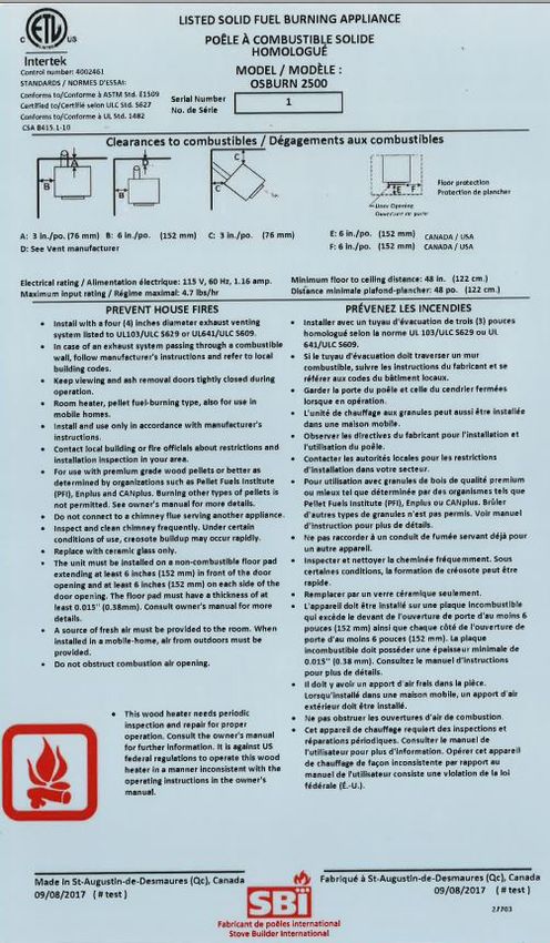
RECOMMENDATIONS
It is highly recommended that this appliance be installed and serviced by professionals who are
certified in the United States by NFI (National Fireplace Institute ® ) or in Canada by WETT (Wood
Energy Technology Transfer) or in Quebec by APC (Association des Professionnels du Chauffage).

If this appliance is not properly installed, combustible materials near it may overheat and
catch fire. To reduce the risk of fire, follow the installation instructions in this manual exactly. Contact
local building or fire officials about restrictions and installation inspection requirements in local area. It
is also recommended to inform your home insurance company.

It may be needed to get a building permit for the installation of this appliance and the venting system
that it is connected to.

Read this entire manual before operating this stove.

                                                                                                                 ENGLISH
SAFETY INFORMATION
                                                 DANGER
             HOT WHILE IN OPERATION, KEEP CHILDREN, CLOTHING AND FURNITURE AWAY.
             CONTACT MAY CAUSE SKIN BURNS.

Using a stove with cracked or broken components, such as glass or baffle may produce an unsafe
condition and may damage the stove.

The viewing door must be closed and latched at all times during operation. The ash drawer access
panel must also be closed during operation.

A smoke detector, a carbon monoxide detector and a fire extinguisher should be installed in the
house. The location of the fire extinguisher should be known by all family members.

Do not disable sensors and safety switches.

GENERAL INFORMATION
It is highly recommended to buy this product from a retailer who can provide installation and
maintenance advice.

The stove will not operate during a power outage. If an outage does occur, check the stove for
smoke spillage. Opening a window will prevent negative pressure and smoke spillage in the room.

This stove has been developed and built to be used as a residential heater. Commercial or industrial
use is prohibited and will void the warranty.

This heating unit is designed to serve as a supplementary heat source. We recommend that a
primary heat source also be available in the home. The manufacturer cannot be responsible for costs
associated with the use of another heating system.

This stove must be connected to a standard 120V / 60Hz, grounded electrical outlet. Do not use
an outlet adapter, an extension cord or sever the grounding plug. Do not route the electrical cord
underneath, in front or over the stove.

Operation Manual - 2500                                                                                Page 3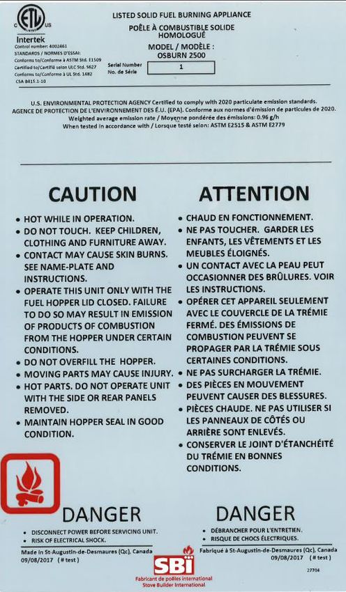
It is important that adequate oxygen is being supplied to the fire for proper combustion. At all time,
          make sure the outside air register is not obstructed by ice, snow or other objects as this will starve the
          fire of air and prevent the proper operation of the stove.

          Mixing of appliance components from different sources or modifying components is prohibited and
          will void the warranty.

          Any modification to the stove that has not been approved in writing by the testing authority is prohibited
          and violates CSA B365 (Canada), and ANSI NFPA 211 (USA).

          Stove builder international inc. (SBI) grants no warranty, implied or stated, for the poor installation or
          lack of maintenance of your appliance and assumes no responsibility of any consequential damages.

          This stove is certified to comply with EPA NSPS 2015 particulate emission standards and is not
          approved for sale after May 15 th 2020.
ENGLISH

                                         REGISTER YOUR WARRANTY ONLINE

                     Should warranty service be required, you must show proof of purchase. Keep
                     your sales invoice. The date on these records establishes the warranty period.
                     If proof of purchase cannot be supplied, the warranty period will be determined
                     from the date of manufacture of the product.

                     We also recommend that you register your warranty online at:

                             https://www.osburn-mfg.com/en/warranty/warranty-registration/

                     Registering your warranty online will help us to quickly track the information we
                     need about your stove.

          AVAILABLE OPTIONS AND ACCESSORIES
          • Hopper extension;                                  • Programmable thermostat;
          • Fresh air kit;                                     • Glass hearth pad;
          • Wall thermostat;

          For more details, visit our web site www.osburn-mfg.com or refer to an authorized dealer.

          Page 4                                                                                 Operation Manual - 2500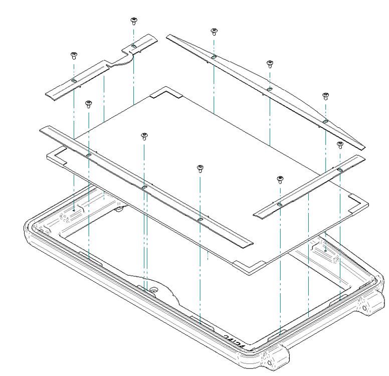
TABLE OF CONTENTS
Recommendations.................................................................................................................... 3
Safety Information..................................................................................................................... 3
General Information................................................................................................................... 3
Available Options and Accessories.......................................................................................... 4
Specifications............................................................................................................................ 7
  Certification Label................................................................................................................8
Fuel............................................................................................................................................ 9
  Recommended Pellets..........................................................................................................9

                                                                                                                                                       ENGLISH
  Storage...............................................................................................................................9
Stove Controls......................................................................................................................... 10
Stove Operation....................................................................................................................... 11
  Before Operating the Stove.................................................................................................11
  First Startup / Beginning of Season.....................................................................................12
  Every Day Startup and Use.................................................................................................12
  Running Out of Pellets........................................................................................................12
  Shutting Down Procedure...................................................................................................13
  Signs of an Overheating Stove............................................................................................13
  Using a Thermostat............................................................................................................14
    Pilot Mode Selection.....................................................................................................14
  Convection adjustments.....................................................................................................14
  Air Intake Adjustments........................................................................................................15
Maintenance............................................................................................................................ 16
  Maintenance Schedule.. ......................................................................................................16
  Recommended tools..........................................................................................................17
  Ash removal.......................................................................................................................17
  Burn pot............................................................................................................................18
  Combustion Chamber. . .......................................................................................................18
  Glass Maintenance.............................................................................................................19
  Replacing the Glass.. ..........................................................................................................19
  Maintaining Door Gasket. . ...................................................................................................21
  Adjusting the Door.. ............................................................................................................21
  Verifying the Door Seal.. ......................................................................................................21
  Heat Exchangers and Exhaust Channels..............................................................................22
  Baffle. . ...............................................................................................................................23
  Maintaining the Venting System. . .........................................................................................24
    Facing a Chimney Fire...................................................................................................24
    Fly Ash and Soot...........................................................................................................24

Operation Manual - 2500                                                                                                                       Page 5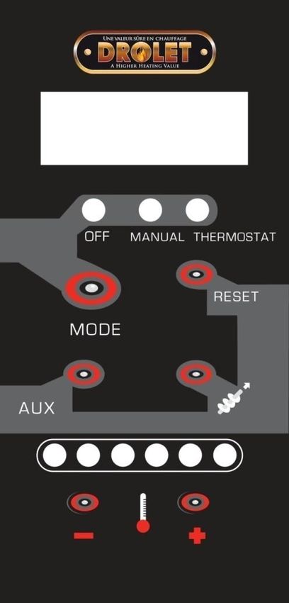
Troubleshooting....................................................................................................................... 25
            Main Error Codes...............................................................................................................25
              CODE P . . .......................................................................................................................25
              CODE E. . .......................................................................................................................25
              CODE L.........................................................................................................................26
              CODE H........................................................................................................................26
              CODE d. . .......................................................................................................................26
              CODE C........................................................................................................................26
              Other possible error codes............................................................................................27
          Recommandations.................................................................................................................. 32
ENGLISH

          Page 6                                                                                                               Operation Manual - 2500
SPECIFICATIONS

    Model                                                                  2500 (OP00025)
    Fuel Type 1                                                            Wood pellets (Premium grade or better)
    Recommended heating area (sq. ft .) 2                                  500 - 2,000 pi 2 (46 - 186 m 2)
    Hopper capacity                                                        60 lb (27,3 kg)
    Maximum burn time 2                                                    51 hours
    Recommended chimney diameter                                           3 in. or 4 in (see installation manual).
    Flue outlet diameter                                                   3 po. (76 mm)
                                                                           ULC/ORD-C441, CAN/ULC S609
    Type of chimney

                                                                                                                                                         ENGLISH
                                                                           UL 641 (TYPE L)
    Approved for alcove installation                                       Yes
    Approved for mobile home installation 3                                Yes
    Shipping weight (without option)                                       286 lb (130 kg)
    Appliance weight (without option)                                      253 lb (115 kg)
    Baffle material                                                        Stainless Steel
    Type of door                                                           Simple, glass with cast iron frame
    Type of glass                                                          Ceramic glass
    Blower                                                                 Included (176 CFM)
                                                                           Min. 47 dBa (+/- 3 dBa)
    Noise level at 6 feet
                                                                           Max. 60 dBa (+/- 3 dBa)
1
    Grades of pellet fuel are determined by organizations such as Pellet Fuels Institute (PFI), ENplus and CANplus.
2
 Recommended heating area and maximum burn time may vary subject to location in home, chimney draft, heat loss factors, climate, fuel type, feed
rate, fuel level, and other variables. The recommended heated area for a given appliance is defined by the manufacturer as its capacity to maintain a
minimum acceptable temperature considering that the space configuration and the presence of heat distribution systems have a significant impact
in making heat circulation optimum.
3
 Mobile home (Canada) or manufactured home (USA): The US department of Housing and Urban Development describes “manufactured homes”
better known as “mobile homes” as followed; buildings built on fixed wheels and those transported on temporary wheels/axles and set on a
permanent foundation. In Canada, a mobile home is a dwelling for which the manufacture and assembly of each component is completed or
substantially completed prior to being moved to a site for installation on a foundation and connection to service facilities and which conforms to the
CAN/CSA-Z240 MH standard.

Operation Manual - 2500                                                                                                                     Page 7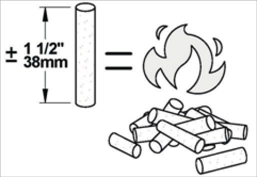
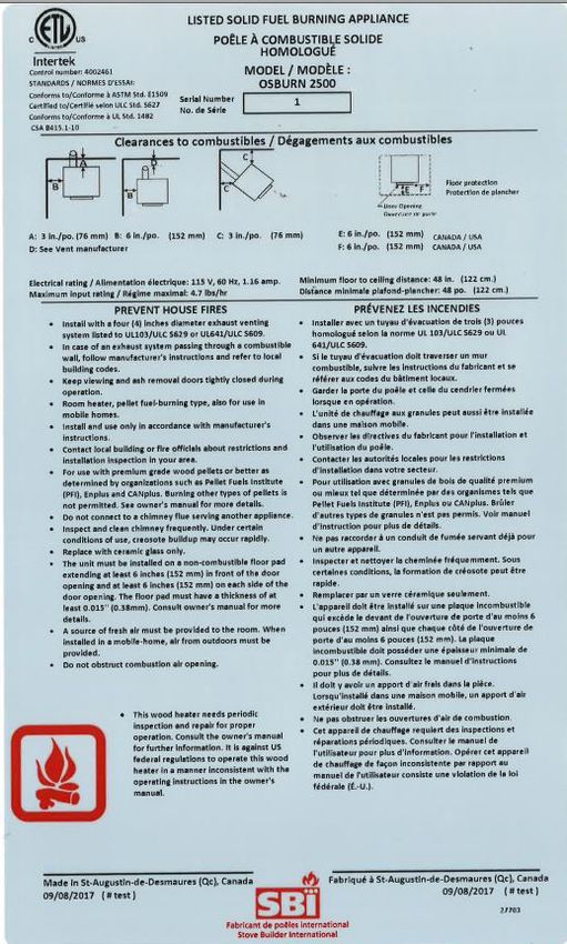
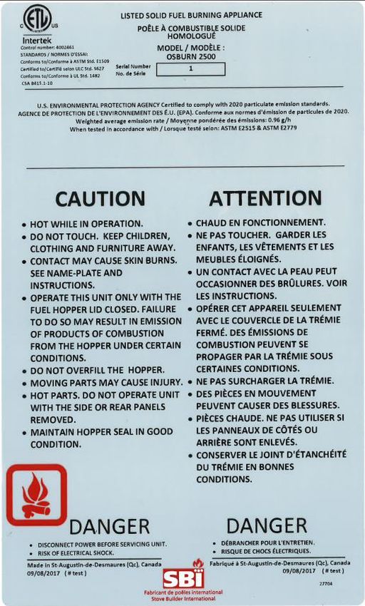
Certification Label
          Since the information given on the certification label affixed to the stove always overrides the
          information published in any other media (owner’s manual, catalogues, flyers, magazines or web sites),
          it is important to refer to it in order to have a safe and compliant installation. In addition, important
          information about the stove can be found (model, serial number, etc.). The certification label is located
          on the inner side of the hopper lid of the stove.
ENGLISH

                         Certification label - Page 1                        Certification label - Page 2

          Page 8                                                                                     Operation Manual - 2500
FUEL

Recommended Pellets
Type: Wood pellet, premium grade or better, certified by PFI, Enplus or CANplus.
Size: Diameter between ¼" or 5/16" and not over 1" long. Longer or thicker pellets will affect the
constancy of pellet feed. The pellets length may vary from one lot to another, even if it comes from the
same manufacturer.

                                                                                                                        ENGLISH
                            Short pellets                                            Long pellets

Ash contents: Less than 1%. Ash contents more than 1% will increase maintenance frequency, create
combustion problems and will increase the stove emission.

Moisture content: Wet pellets will be very hard to ignite and will greatly affect the feeding process of the
stove. Using dry pellets will maintain the performance of your stove.

                          Note that the pellets quality may vary depending on the manufacturer. It can also vary from
                          one bag to another, even if it comes from the same manufacturer. It is recommended to
                          try several different manufacturers to find the one that best suits your use. Then, buy the
                          pellets in lots of several tons to ensure satisfaction.

                          Burning other types of pellets is prohibited. It violates the building codes for which the
                          stove has been approved and will void the warranty.

Storage
Pellets should remain in their original packaging until ready for use.

Pellets bags should be stored in a dry and well ventilated area, if possible. If they are to be stored
outside, remember that pellets bags are not water tight. It is best to keep the pallet wrapper as intact
as possible and cover it with a tarp.

Having a bag or two in the same room as the stove for refueling is a good idea. The minimum
clearances to combustible materials and the space required for refilling and ash removal needs to be
respected.

DO NOT STORE FUEL WITHIN STOVE MINIMUM CLEARANCES TO COMBUSTIBLE.

Operation Manual - 2500                                                                                        Page 9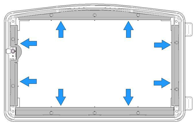
STOVE CONTROLS
          The stove, the pellet feeding system and the blowers are controlled by a control panel on the right-
          hand side of the stove. The control panel buttons and display areas are as follows:

                                             A

                                             B
ENGLISH

                                                                                 2
                                             1

                                             3                                   4

                                                                                 C
                                             5                                   6

                                                           Stove controls

            No      Description
             A      Control panel display area.

             B      Stove state display area.

             C      Stove heating intensity display area, level 1 to 6.

             1      MODE: the «MODE» button is used to either turn off the appliance (OFF), turn it on in manual
                    operation (MANUAL) or in thermostatic operation (THERMOSTAT).

             2      RESET: The «RESET» button is used to reset the stove after the appearance of most of the
                    warning codes.

             3      AUX: The «AUX» button is used to adjust the convection air speed.

             4      AUGER: The «Auger» button is used to fill the auger with pellets.

             5      MINUS: The « - » button is used to reduce the pellet feeding rate thus reducing the heat
                    output of the stove.

             6      PLUS: The « + » button is used to increase the pellet feeding rate thus increasing the heat
                    output of the stove.

          Page 10                                                                              Operation Manual - 2500
STOVE OPERATION
Before Operating the Stove
• Make sure appliance and venting are installed as per manufacturer’s instructions;
• Read and follow this operation manual;
• Make sure all tools and accessories has been removed from inside the stove;
4
No Tools / Accessories
ENGLISH
1 Baffle
2 Warning sheet
3 Humidity absorbant
3
4 Users manual
2
1
Tools and accessories located inside the stove
• Make sure the baffle is installed as shown below:
Baffle final location in the stove
• Make sure that the burn pot is in place properly and that there is enough pellets in the hopper.
• The stove handle is removable. When the stove is in
operation, it must be stored behind the stove, as
shown in the «door handle location» figure.
Door handle location
Operation Manual - 2500 Page 11First Startup / Beginning of Season
Before starting the stove, the burn pot, the baffle and the access panels must be installed correctly.
The stove and hopper must have been emptied of all tools and accessories (see «Before operating
the stove»). In addition, all doors and covers must be closed and the vent system must be properly
installed and sealed.
Fill the hopper with pellets and press the «MODE» button once to start the stove in manual mode
(MANUAL) or twice to start the stove in thermostat mode (THERMOSTAT). For the first fire of the
season, or if the unit has run out of pellets, press the «AUGER» button first, then start the stove in
the desired mode. When the stove is turned on, it will automatically ignite. No fire starter is required.
If the stove does not light within 20 minutes of starting, the message «CODE L» will appear in the
display area. See the troubleshooting section for details.
ENGLISH
During the first few fires, the stove will emit an odor and a small amount of fumes as the high temperature paint
cures or becomes seasoned to the metal. Maintaining smaller fires will minimize this. Avoid placing items on
stovetop during this period to avoid damaging the paint surface. Make sure the room is well-ventilated. Open
windows. Odors and fumes released during this process are unpleasant but they are not toxic.
Make two or three low intensity fires to initiate the paint hardening and the components
conditioning process. Then, make high intensity fires until the stove no longer smell of paint.
NEVER USE A GRATE OR OTHER MEANS TO SUPPORT THE FUEL. USE ONLY
THE APPROVED BURN POT FOR THIS STOVE AND DO NOT MODIFY IT.
Every Day Startup and Use
Before startup, make sure that the recommended maintenance has been performed according to the
schedule (see «Maintenance» section). Fill the hopper and press the «MODE» button once to start the
stove in manual mode (MANUAL) or twice to start the stove in thermostat mode (THERMOSTAT).
By pressing on the «+» or «-» buttons, it is possible to increase or decrease the feed rate, and thereby
the intensity level of the stove. Intensity levels change, from 1 to 6, can be visualized by the red light
in the heating intensity display area.
Running Out of Pellets
If the stove runs out of pellets, the fire will slowly go out. The convection blower will remain on until
the heat sensor reads 115 °F. The cooling cycle will take a few minutes before all other motors stop.
When this temperature is reached, the message «CODE E» will appear.
Restarting the stove will only be possible when all blowers are off (about 10 minutes after the error
message appears). Press «RESET» and fill the hopper. Press the «AUGER» button and then press the
«MODE» button on the home page to start the stove in the desired mode.
Refueling
When the stove is running, the hopper lid can be opened for 90 seconds to refill the hopper before
the stove stops. A beeping sound that will intensify every 30 seconds can be heard. After 90 seconds,
if the hopper lid is still open, the stove will stop and display the message «CODE d». For more
information, see the troubleshooting section for details. When the stove is stopped, there is no time
limit for filling the hopper. Note that opening the hopper lid will stop the auger from feeding the pellet stove.
THE HOPPER LID MUST BE CLOSED AT ALL TIMES EXCEPT WHEN REFULING.
Page 12 Operation Manual - 2500DO NOT OVERFILL THE HOPPER.
Shutting Down Procedure
To turn the stove off, press the «MODE» button until the red light is in the OFF position. The cooling
cycle will take a few minutes. The blowers will continue to work while the stove is cooling down.
NEVER UNPLUG THE POWER CORD TO TURN OFF THE STOVE.
Signs of an Overheating Stove
Choosing a stove that is too small for the house in which it is installed may cause the stove to
ENGLISH
overheat since it will have to operate at maximum setting for most of the time to achieve a comfortable
temperature. The life expectancy of the components and the stove will be reduced.
Under normal conditions, the flame must have a bright yellow color, be very active and stable. If the
flame becomes lazy, very high and orange, it is a sign of malfunction.
Usually, overheating issues are caused by too much restriction in the venting system, a blocked heat
exchanger, a lack of combustion air or a lack of maintenance.
If the stove is overheating, it will become very hot. If the stove gets too hot, it will shut itself down,
showing the «CODE H» message.
If this occurs once, wait for the stove to cool down and perform the weekly maintenance of the
stove suggested in the maintenance calendar. Carefully inspect the venting system. Have it swept,
if necessary. Press on the «MODE» and «RESET» buttons simultaneously for 3 seconds to reset the
stove.
If this occurs more than once, contacting the retailer may be helpful in order to receive some advice
for this code not to happen again.
After three occurence of an H code, the stove control will be locked and it will be impossible to reset
it and restart the stove. Before unlocking the stove control, perform the biannual maintenance
suggested in the maintenance calendar. Carefully inspect the venting system. Have it swept, if
necessary. When maintenance is done, press the following buttons, one at a time : «RESET», «MODE»,
«+», «-», then press on the «AUGER» for 5 seconds.
If any external part of the stove begins to glow red, the
stove is overheating. Immediately turn the stove off.
Do not unplug it and do not open the door.
Unpluging the stove will disable all the safety features
of the stove.
Operation Manual - 2500 Page 13Using a Thermostat
Using a thermostat will help maintain a constant temperature throughout the house. A Low voltage
thermostat (24 volts) is required. A fixed wall mount or hand held model can be used.
To use the stove in thermostat mode, press the «MODE» button until the «THERMOSTAT» position. is
reached. Then, select the intensity level using the «-» or «+» buttons. In thermostatic mode, the stove
will operate at the selected intensity level until the room temperature has reached the programmed
level on the thermostat.
Pilot Mode Selection
The factory setting of the pilot mode is «AUTO». To change it, press on the «-» and «MODE» buttons
simultaneously for 3 seconds. The selected mode will appear on the control panel display area.
ENGLISH
Pilot AUTO (Intensity level 1)
When the thermostat stops calling for heat, the unit will remain at its lowest intensity level (#1) and will
shut down after 15 minutes, if there is no call for heat.
Pilot AUTO (Intensity level 2 to 6)
When the thermostat stops calling for heat, the unit automatically switch to its lowest intensity level
(#1) until the thermostat requires heat again. The stove will shut down after 45 minutes, if there is no
call for heat.
Pilot ON:
When the thermostat stops calling for heat, the unit automatically switch to its lowest intensity level
(#1) until the thermostat calls for heat again. The stove will never shut down, even if there is no call
for heat.
To avoid premature wear of the components, it is recommended to use the «Pilot ON» mode
during the coldest months and the «Pilot AUTO» mode during the warmest months.
Convection adjustments
Each intensity level has been programmed with an optimum convection speed. However, it is possible
to increase the convection air speed by pressing the «AUX» button. All intensity levels can be increased
at the exception of the intensity level 6, which is already at its maximum speed.
Page 14 Operation Manual - 2500Air Intake Adjustments
It is possible to adjust the amount of combustion air entering the stove. Using the stove to the lowest
setting will reduce missed ignition, will ignite pellets faster and will reduce the blackening of the
window, when using high quality pellets. If you should find one bag of pellets harder to ignite and to
burn, opening the air control will help.
To open or close the manual air control, open the right decorative panel and locate the air intake. Push
down the tab and slide upwards to decrease the air supply and downwards to increase the air supply.
ENGLISH
Operation Manual - 2500 Page 15MAINTENANCE
DANGER DANGER
DISCONNECT ALL POWER
NEVER CLEAN WHEN HOT. BEFORE SERVICING THE
APPLIANCE.
Maintenance Schedule
This schedule should be used as a reference only for a normal use of the stove. The cleaning frequency may
vary depending on the type of fuel used.
COMPONENTS WEEKLY TWICE A YEARLY
ENGLISH
(±250 POUNDS) YEAR (± 2 TONS)
(± 1 TON)
Baffle Vacuum
Glass air wash system Vacuum
Burn Pot Scrape / Vacuum
Glass Clean
Ash drawer Empty / Vacuum
Combustion chamber Vacuum Brush / Vacuum
Heat exchanger Brush Scrape / Vacuum
Exhaust channels Vacuum
Exhaust blower Vacuum
Combustion blower Inspect
Convection blower Vacuum
Venting system Inspect / Sweep Clean and Sweep
Gaskets Inspect
Hopper Empty / Vacuum
Cleaning of the stove and its venting system is important, especially at the end of the heating
season to minimize corrosion during the summer months, caused by accumulated ash.
NEGLECTING THE RECOMMENDED CLEANING AND MAINTENANCE OF THE
APPLIANCE COULD RESULT IN POOR PERFORMANCE AND A SAFETY HAZARD.
Page 16 Operation Manual - 2500Recommended tools
Universal brush Scraper
ENGLISH
Steel brush Round brush + rod
Glass cleaner Ash vacuum
Ash removal
DANGER
NEVER VACUUM THE ASHES WHEN THEY ARE HOT. THE ASHES MUST BE
COOLED BEFORE SERVICING.
Ash drawer removal
Operation Manual - 2500 Page 17The ashes should be placed in a metal container with a tight lid. The container should be placed
on a non-combustible surface, away from any material that may catch fire. If the ash is to be
buried or locally dispersed, it should be kept in the closed container until it is completely cooled.
The use of a domestic, central or commercial vacuum cleaner to maintain the stove is not
recommended. The use of an ash vacuum cleaner is strongly recommended.
Burn pot
ENGLISH
Remove and empty burn pot Scrape, if necessary
Combustion Chamber
Clean the combustion chamber by vaccuming the cooled ashes. When necessary, brush the walls and
vacuum the ashes afterwards.
You can also push the ashes into the ash drawer through the opening at the bottom of the firebox. In
this case alone, the ashes do not have to be cold.
Remove ash plug to sweep ashes in the ash drawer
Page 18 Operation Manual - 2500Glass Maintenance
Vacuum ashes accumulated in the airwash system of the glass. This allows optimum air flow and
prevents the window from sooting up.
Clean door glass when necessary. The use of a stove glass cleaner is recommended. Regular household
glass cleaners will not remove creosote properly.
ENGLISH
Vacuum ashes acumulated in the airwash system
NEVER USE ABRASIVE CLEANERS ON THE GLASS OR ON ANY PLATED
PARTS.
DO NOT CLEAN THE GLASS WHEN IT IS HOT.
DO NOT FORCE, STRIKE, SLAM OR ANY OTHER BEHAVIOR THAT COULD
FRAGILIZE THE GLASS DOOR.
DO NOT USE THE STOVE IF THE GLASS IS MISSING, CRACKED OR BROKEN.
Replacing the Glass
1. Remove the door and place it on a table,
face-down on something soft like a cushion
of rags or piece of carpet
2. Remove the 10 screws holding the door glass
retainers and carefully remove any loose
pieces of glass from the doorframe. Dispose
of all broken glass properly. A broken glass
should be replaced with a 13 7/8" x 8 5/8"
ceramic glass, 5 mm thick.
ALWAYS WEAR GLOVES WHEN
HANDLING BROKEN GLASS.
Glass retainer removal
Operation Manual - 2500 Page 193. Remove the stove ciment in the door corners (see dark spots in the figure below). When done,
reinstall the new glass.
ENGLISH
Stove cement location Reinstalling the new glass
5. Put stove cement in the door corners, as shown on the image above.
6. Reinstall the glass door retainers making sure the stove cement is pressed down by the retainers.
Push the retainers towards the door frame to make sure there is no gag between the retainers
and the door frame and screw them in place. Do not over-tighten the screws as this will make the
glass crack under strong heat.
Push the retainers towards the door frame
8. Reinstall the door and wait 24 hours before using the stove again.
The replacement glass must be purchased only from an authorized dealer. Tempered glass or ordinary glass is
not suitable for high temperatures.
When changing the glass, make sure that the glass gaskets are in the same place as the originals to maintain
proper operation of the airwash system of the glass.
Page 20 Operation Manual - 2500Maintaining Door Gasket
The door gasket must be kept in good condition. After a while, the gasket wears out and compresses.
An adjustment of the door may then be necessary (see section «Adjusting the door»). If door adjustment
is not sufficient, the door gasket must be replaced with an original gasket.
If the stove door does not close tightly, it will be difficult to keep the glass clean and the flue gases
could leak into the room.
Adjusting the Door
In order to achieve optimal performance, the door must be completely sealed with the combustion
chamber. The gasket must therefore be inspected periodically in order to obtain an airtight fit. The
sealing can be improved with a simple adjustment of the latch mechanism.
ENGLISH
Remove the retaining pin by pulling and turning with a pair of pliers. Turn the handle one turn
counterclockwise to increase the pressure between the door frame and the stove structure. Reinstall
the retaining pin using a hammer.
Removing the retaining pin Reinstalling the retaining pin
Verifying the Door Seal
Test the door seal by closing and latching the door on a strip of paper. Test all around the door. The
paper should not slip out easily. If it does, see the maintenance section in the operation manual.
Door sealing test
Operation Manual - 2500 Page 21Heat Exchangers and Exhaust Channels
Activate the cleaning rod a couple of times
Brush and vaccum inside the heat exchanger channel, when necessary.
ENGLISH
7/16''
2x
Remove screws (2x) Pull on left side panel
2x
Then, pull Remove wing nuts (2x)
1
2
Brush and vacuum Replace gasket, if necessary
Page 22 Operation Manual - 2500Brush and vacuum inside the exhaust channel, when necessary.
2x
Remove wing nuts (2x) Remove access panel
ENGLISH
Brush and vacuum combustion residues Replace gasket, if necessary
Baffle
Remove and clean baffle. Don’t forget to put it back in place.
Remove and clean baffle
Operation Manual - 2500 Page 23Maintaining the Venting System
REGULARLY INSPECT THE VENTING SYSTEM, GASKETS AND OTHER SEALING PARTS TO
PREVENT SMOKE AND COMBUSTION GASES FROM ESCAPING.
Sweeping the vent system can be difficult and dangerous. For inexperienced people, it is best to hire
a professional chimney sweep to inspect and clean the system.
For an experienced person who would like to perform the sweeping himself, the most effective
method is to use a 3" or 4" brush, depending on the installation. Start at the top of the vent system
and brush down, so that the ash, soot and creosote residues come off the inner surface and fall into
the bottom of the venting system, where they can be removed easily.
The venting system must be maintained in good condition and well maintained.
ENGLISH
IF A SIGNIFICANT LAYER OF CREOSOTE HAS ACCUMULATED (3 MM (1/8") OR MORE), IT
MUST BE REMOVED IMMEDIATELY TO ELIMINATE CHIMNEY FIRE HAZARD.
Facing a Chimney Fire
1. Evacuate family members and animals from the building, and then call the fire department.
2. Turn off the unit. Do not unplug it!
3. If possible, use a chemical fire extinguisher, baking soda or sand to control the fire. Do not use
water as this may cause hazardous vapor explosions.
4. Do not use the stove until the venting system and the stove have been inspected by a qualified
chimney sweeper or fire inspector.
Fly Ash and Soot
Combustion products contain small particles of fly ash. Fly ash can accumulate particularly in the
horizontal sections of exhaust pipe and restrict the flow of combustion gases. Incomplete combustion
during start-up, shut-down or improper use of the stove will cause soot to build up in the exhaust
system. The exhaust system must be inspected at least twice a year to determine if sweeping
is required.
Page 24 Operation Manual - 2500TROUBLESHOOTING
Most common problems are generally caused by one or many of the following factors:
1. Wrong operation or lack of maintenance;
2. Bad installation;
3. Poor quality combustible;
4. Component failure;
The stove is equipped with a PC board which informs the user when a problem occurs. It is therefore
important not to unplug the stove when it is in operation, as it will be impossible to see the message
and correct the problem. In addition, unplugging the stove will disable all the safety functions.
In order to obtain a fast and personalized service, the manufacturer’s model number and serial number must
be provided when contacting the retailer or manufacturer. (This information can be found on the name plate
ENGLISH
inside the hopper lid).
Main Error Codes
This section contains the main error codes, possible causes and solutions. Visit our website
www.osburn-mfg.com/en/products/pellet-stoves/ to download the detailed troubleshooting
guide.
After an error code appears, the stove will stop by itself and begin a cooling cycle. To restart the stove,
press the «RESET» button and then the «MODE» button. The stove will restart only when the cooling
cycle is completed.
DANGER DANGER
NEVER HANDLE OR REPLACE DISCONNECT ANY POWER SOURCE
COMPONENT WHEN THE STOVE BEFORE HANDLING OR REPLACING A
IS HOT. COMPONENT.
CODE P
The flue is blocked. One of the following components is obstructed or blocked by ashes or by a foreign
object : air intake shutter, combustion blower, burn pot, heat exchangers and exhaust channels,
exhaust blower or venting system. Refer to the «Maintenance» section.
The venting system is not properly installed. The venting system must comply with the installation
manual and with the venting system manufacturer’s instructions.
A back draft occurred inside the flue. This can occur on a very windy day or if the venting system does
not have a proper termination.
CODE E
The stove ran out of pellets. Fill the hopper.
The holes in the burn pot are clogged. Remove and clean the burn pot. The holes must not be
obstructed. Refer to the «Maintenance» section.
The auger is jammed or there is a faulty motor. Test the motor. Refer to the «Testing a Component»
technical sheet on our web site. During testing, the hopper lid must be closed. If one the motor does
not seem to be working, either it is defective or the auger is jammed.
Operation Manual - 2500 Page 25Faulty thermistor. When the stove is cold, press on «+» and «AUGER» to display the temperature.
Displayed temperature must be the ambiant one. If this is the case, turn the stove on. After 10
minutes, if the value has not increased, the thermistor is disconnected or defective.
CODE L
The holes in the burn pot are clogged. Remove and clean the burn pot. The holes must not be
obstructed. Make sure the tube around the igniter is not filled with ash. Refer to the «Maintenance»
section.
Poor quality combustible. The fuel use must be of good quality. Refer to the «Fuel» section.
Defective ignitor. Test ignitor. Refer to the technical sheet «Testing a component» on our web site. If it
works properly, the tip should be glowing red in less than two minutes.
ENGLISH
Faulty thermistor. When the stove is cold, press on «+» and «AUGER» to display the temperature.
Displayed temperature must be the ambiant one. If this is the case, turn the stove on. After 10
minutes, if the value has not increased, the thermistor is disconnected or defective.
CODE H
The main cause of a stove overheating is lack of maintenance. Any overheating code should be followed by
thorough maintenance of the unit and a venting system inspection .
The overheating code may also appear if the burn pot or the baffle is not installed correctly, or if the
convection fan is defective.
After three repetitions of an overheating code, it will not be possible to restart the stove.
Before unlocking the stove, do the biannual
maintenance suggested in the maintenance
schedule. Carefully inspect the venting system.
Have it swept, if necessary.
For more information, see the «signs of an overheating stove».
CODE d
The hopper lid remained open for more than 90 seconds. As a safety measure, the auger stops
feeding pellets as soon as the hopper lid opens. It will resume normal operation as soon as the lid is
closed. If the lid remains open for more than 90 seconds, the stove stops.
The hopper lid switch is faulty or improperly connected. Test the switch. See the technical data sheet
«Checking the Status and Testing a Component» on our web site. If the switch does not work, it may
be faulty or improperly connected.
CODE C
The current was interrupted during operation. After the cooling cycle, the stove restarts using the last
settings. For short-term power failure (less than 5 seconds), the stove will continue to operate at the
selected speed.
Page 26 Operation Manual - 2500Other possible error codes
CODE DESCRIPTION
Reverse polarity in the socket. This error does not prevent the stove from operating
n
normally but the polarity should be corrected by a certified electrician.
FE The exhaust blower fuse is defective.
FL The ignitor fuse is defective.
FC The convection blower fuse is defective.
FV The auger fuse is defective.
ENGLISH
FB The combustion blower fuse is defective.
For a detailed troubleshooting guide and component replacement data sheets, visit our product web page at
www.osburn-mfg.com/en/products/pellet-stoves/.ca
Operation Manual - 2500 Page 27The warranty of the manufacturer extends only to the original retail purchaser and is not transferable. This warranty covers brand new
products only, which have not been altered, modified nor repaired since shipment from factory. Proof of purchase (dated bill of sale),
model name and serial number must be supplied when making any warranty claim to your OSBURN dealer.
This warranty applies to normal residential use only. Damages caused by misuse, abuse, improper installation, lack of
maintenance, over firing, negligence or accident during transportation, power failures, downdrafts, venting problems or
under-estimated heating area are not covered by this warranty. The recommended heated area for a given appliance is defined
by the manufacturer as its capacity to maintain a minimum acceptable temperature considering that the space configuration
and the presence of heat distribution systems have a significant impact in making heat circulation optimum.
This warranty does not cover any scratch, corrosion, distortion, or discoloration. Any defect or damage caused by the use of
unauthorized or other than original parts voids this warranty. An authorized qualified technician must perform the installation in
accordance with the instructions supplied with this product and all local and national building codes. Any service call related to an
improper installation is not covered by this warranty.
ENGLISH
The manufacturer may require that defective products be returned or that digital pictures be provided to support the claim. Returned
products are to be shipped prepaid to the manufacturer for investigation. Transportation fees to ship the product back to the purchaser
will be paid by the manufacturer. Repair work covered by the warranty, executed at the purchaser’s domicile by an authorized qualified
technician requires the prior approval of the manufacturer. All parts and labour costs covered by this warranty are limited according to
the table below.
The manufacturer, at its discretion, may decide to repair or replace any part or unit after inspection and investigation of the defect. The
manufacturer may, at its discretion, fully discharge all obligations with respect to this warranty by refunding the wholesale price of any
warranted but defective parts. The manufacturer shall, in no event, be responsible for any uncommon, indirect, consequential damages
of any nature, which are in excess of the original purchase price of the product. A one-time replacement limit applies to all parts
benefiting from lifetime coverage. This warranty applies to products purchased after June 1st, 2015.
*Subject to limitations above. **Picture required.
Labour cost and repair work to the account of the manufacturer are based on a predetermined rate schedule and must not exceed the
wholesale price of the replacement part.
Shall your unit or a components be defective, contact immediately your OSBURN dealer. To accelerate processing of your warranty
claim, make sure to have on hand the following information when calling:
Your name, address and telephone number; Serial number and model name as indicated on the
Bill of sale and dealer’s name; nameplate fixed to the back of your unit;
Installation configuration; Nature of the defect and any relevant information.
Before shipping your unit or defective component to our plant, you must obtain an Authorization Number from your OSBURN
dealer. Any merchandise shipped to our plant without authorization will be refused automatically and returned to sender.
Pellet_Revision :
Page 28 Operation Manual - 2500This document is available for free download on the Stove Builder International inc. manufacturer’s website. It is a copyrighted document. 250, rue de Copenhague, Resale is strictly prohibited. The manufacturer may update St-Augustin-de-Desmaures (Québec) Canada this document from time to time and cannot be responsible G3A 2H3 for problems, injuries, or damages arising out of the use 418-908-8002 of information contained in any document obtained from www.osburn-mfg.com unauthorized sources. tech@sbi-international.com
Manuel d’opération
                                               2500

                                                                                                              ENGLISH
                                          (modèle OP00025)

                                                                                                              FRANÇAIS
                                                                    Essais de sécurité faits conformément
                                                                       aux normes ULC S627, UL 1482
                                                                      et ASTM E1509 par un laboratoire
                                                                                 accrédité.

                                                             L’INSTALLATION PAR UN
                                                               PROFESSIONNEL EST
                                                           FORTEMENT RECOMMANDÉE

CONTACTEZ LE SERVICE MUNICIPAL DU BÂTIMENT OU DES INCENDIES POUR CONNAÎTRE LES RESTRICTIONS ET LES
EXIGENCES D’INSPECTION ET D’INSTALLATION DANS VOTRE RÉGION.

LISEZ CE MANUEL AU COMPLET AVANT L’INSTALLATION DE CE POÊLE. IL EST IMPORTANT DE RESPECTER INTÉGRALEMENT
LES DIRECTIVES D’INSTALLATION. SI LE POÊLE N’EST PAS INSTALLÉ CORRECTEMENT, IL PEUT EN RÉSULTER UN INCENDIE, DES
BLESSURES CORPORELLES OU MÊME LE DÉCÈS.
                                                                                                                   2018-01-23

   LIRE LE PRÉSENT MANUEL ET LE CONSERVER POUR CONSULTATION
Imprimé au Canada                                                                                       45910OF
RECOMMANDATIONS
Il est fortement recommandé que cet appareil de chauffage soit installé par un professionnel
certifié aux États-Unis par le NFI (National Fireplace Institute ®) ou au Canada par WETT (Wood
Energy Technology Transfer) ou au Québec par l’APC (Association des Professionnels du Chauffage).
Lorsque l’appareil n’est pas installé correctement, les matériaux combustibles à proximité
peuvent surchauffer et s’enflammer. Pour réduire les risques d’incendies, suivre les instructions
d’installation de ce manuel soigneusement. Consulter le code du bâtiment local ou contacter le
service des incendies pour connaître les restrictions et les exigences d’inspection et d’installation de
la région. Il est également recommandé d’aviser la compagnie d’assurance habitation.
Il se peut qu’un permis soit requis pour l’installation du poêle et du système d’évent sur lequel il est
branché.
Lire ce manuel au complet avant d’opérer cet appareil.
CONSIGNES DE SÉCURITÉ
DANGER
FRANÇAIS
CHAUD LORSQU’EN FONCTION. TENIR LES ENFANTS, LES VÊTEMENTS ET
LES MEUBLES ÉLOIGNÉS. TOUT CONTACT AVEC LA PEAU PEUT CAUSER DES
BRÛLURES.
L’utilisation d’un poêle avec des composants fissurés ou brisés, comme la vitre ou le coupe-feu
pourrait causer une situation dangereuse et pourrait endommager le poêle.
La porte du poêle doit demeurer fermée et enclenchée pendant l’utilisation. Le panneau d’accès du
tiroir à cendre doit également être fermé pendant l’utilisation.
Un détecteur de fumée, un détecteur de monoxyde de carbone ainsi qu’un extincteur devraient être
installés dans la maison. L’emplacement de l’extincteur devrait être connu de tous les membres de la
famille.
Ne pas désactiver les capteurs et les interrupteurs de sécurité.
INFORMATIONS GÉNÉRALES
Il est fortement recommandé d’acheter ce produit chez un détaillant pouvant fournir des conseils sur
son installation et son entretien.
Le poêle ne fonctionne pas sans électricité. Si une panne électrique se produit, vérifier si de la
fumée s’échappe du poêle. Ouvrir une fenêtre préviendra une pression négative et un épanchement
de fumée dans la maison.
Ce poêle a été conçu et développé pour être utilisé comme chauffage d’appoint résidentiel. Un
usage commercial ou industriel est interdit et annulera la garantie.
Une source de chauffage primaire doit être disponible dans la résidence. Cet appareil de
chauffage doit être utilisé comme chauffage d’appoint. Le manufacturier ne peut être tenu
responsable des coûts du chauffage additionnel pouvant être engendrés par une source de chauffage
alternative.
Page 32 Manuel d’opération- 2500Ce poêle doit être branché dans une prise standard de 120V / 60Hz, avec mise à la terre. Ne pas
utiliser de rallonge électrique ou d’adaptateur de prise électrique. Ne pas endommager ou enlever la
mise à la terre. Ne jamais faire passer le cordon d’alimentation électrique en avant, au-dessus ou en
dessous du poêle.
Il est important qu’une quantité d’oxygène suffisante soit apportée au feu pour une bonne combustion.
Durant la saison hivernale, s’assurer que la prise d’air frais n’est pas obstruée (glace, neige, etc.) car
cela privera le feu d’air et empêchera le bon fonctionnement du poêle.
L’utilisation de composants provenant d’autres appareils ou la modification des composants actuels
du poêle sont interdites et annuleront la garantie.
Toute modification de l’appareil qui n’a pas été approuvée par écrit par l’autorité d’homologation ou
le manufacturier est interdite et viole les normes CSA B365 (Canada) et NFPA 211 (É.-U.).
SBI - Fabricant de poêles international inc. n’assume aucune garantie implicite ou explicite liée à
la mauvaise installation de l’appareil et n’assume aucune responsabilité pour tout dommage qui en
résulterait.
Ce poêle à granules est certifié conforme à la norme 2015 d’émission de particules. Il n’est pas
approuvé pour être vendu après le 15 mai 2020.
FRANÇAIS
ENREGISTRER VOTRE GARANTIE EN LIGNE
Si votre appareil requiert des réparations pendant la période de garantie, vous
devrez présenter une preuve d’achat. Conserver la preuve d’achat. La date
indiquée sur ces documents établie la période de garantie. Si celle-ci ne peut être
présentée, la période de garantie sera déterminée selon la date de fabrication du
produit.
Nous vous recommandons également d’enregistrer votre garantie en ligne au
https://www.osburn-mfg.com/fr/garantie/enregistrement-garantie/
L’enregistrement de votre garantie nous aidera à trouver rapidement les
informations requises sur votre appareil.
ACCESSOIRES ET OPTIONS DISPONIBLES
• Extension de trémie ; • Contrôle à distance thermostatique ;
• Ensemble d’entrée d’air frais ; • Protection de plancher en verre ;
• Thermostat mural ;
Pour plus de détails, consulter le site web www.osburn-mfg.com ou se référer à un marchand autorisé.
Manuel d’opération - 2500 Page 33TABLE DES MATIÈRES
Recommandations.................................................................................................................. 32
Consignes de sécurité............................................................................................................ 32
Informations générales........................................................................................................... 32
Accessoires et options disponibles........................................................................................ 33
Spécifications.......................................................................................................................... 36
Plaque d’homologation.......................................................................................................37
Combustibles........................................................................................................................... 38
Granules recommandés......................................................................................................38
Entreposage......................................................................................................................38
Contrôles de l’appareil............................................................................................................ 39
Opération de l’appareil............................................................................................................ 40
Avant de démarrer l’appareil...............................................................................................40
FRANÇAIS
Premier allumage / Début de saison....................................................................................41
Démarrage quotidien..........................................................................................................41
Manque de granules...........................................................................................................41
Procédure d’arrêt...............................................................................................................42
Les signes de surchauffe....................................................................................................42
Sélection du mode pilot. . ...............................................................................................43
Ajustement de la vitesse de l’air de convection.. ...................................................................43
Ajustement de l’entrée d’air................................................................................................44
Entretien................................................................................................................................... 45
Calendrier d’entretien.........................................................................................................45
Équipements recommandés................................................................................................46
Enlèvement des cendres.....................................................................................................46
Pot de combustion.............................................................................................................47
Chambre à combustion.. .....................................................................................................47
Entretien de la vitre. . ...........................................................................................................48
Remplacer la vitre.. .............................................................................................................48
Entretien du cordon de porte..............................................................................................49
Ajustement de la porte.. ......................................................................................................50
Vérification de l’étanchéité de la porte.................................................................................50
Échangeur de chaleur et canalisation d’évacuation...............................................................51
Coupe-feu.........................................................................................................................52
Entretien du système d’évent..............................................................................................53
Faire face à un feu de cheminée....................................................................................53
Cendres volantes et suie. . ..............................................................................................53
Page 34 Manuel d’opération- 2500You can also read