Hydraulic High Pressure Controller, Model CPC8000-H - Hydraulic High Pressure Controller, Model CPC8000-H - Mensor
←
→
Page content transcription
If your browser does not render page correctly, please read the page content below
Operating instructions

Hydraulic High Pressure Controller, Model CPC8000-H                    EN

            Hydraulic High Pressure Controller, Model CPC8000-H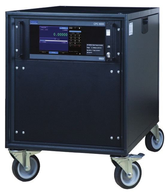
EN Operating instructions model CPC8000-H                                                        Page      3 - 88

© 06/2020, Mensor, LP. All rights reserved.
Mensor is a registered trademark of Mensor, LP.
All other brand and product names are trademarks or registered trademarks of their respective companies.

Prior to starting any work, read the operating instructions!
Keep for later use!
                                                                                                                    PN 0018708001C 03/2021 EN

 2              WIKA operating instructions hydraulic high pressure controller, model CPC8000-H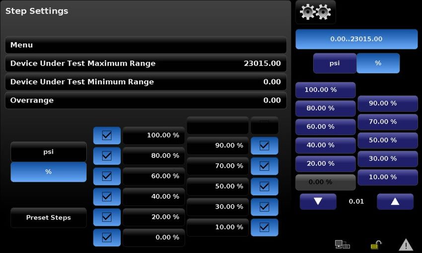
Contents
                            Contents
                            1. General Information                                                                                                                                         7
                              1.1 Warranty  .   .   .   .   .   .   .   .   .   .   .   .   .   .   .   .   .   .   .   .   .   .   .   .   .   .   .   .   .   .   .   .   .   .   .   .  8
                              1.2 Radio Frequency Emission Notices  .  .  .  .  .  .  .  .  .  .  .  .  .  .  .  .  .  .  .  .  .  .  .  .  .  .  . 8
                                 1.2.1     FCC Emission Notice  .   .   .   .   .   .   .   .   .   .   .   .   .   .   .   .   .   .   .   .   .   .   .   .   .   .   .   .   .   .  8           EN
                                 1.2.2     CE Emission Notice   .   .   .   .   .   .   .   .   .   .   .   .   .   .   .   .   .   .   .   .   .   .   .   .   .   .   .   .   .   . 8
                              1.3 Software License Agreement  .   .   .   .   .   .   .   .   .   .   .   .   .   .   .   .   .   .   .   .   .   .   .   .   .   .   .   .   . 8
                              1.4 Mensor Service Plus  .  .  .  .  .  .  .  .  .  .  .  .  .  .  .  .  .  .  .  .  .  .  .  .  .  .  .  .  .  .  .  . 9
                                 1.4.1     After the Warranty  .  .  .  .  .  .  .  .  .  .  .  .  .  .  .  .  .  .  .  .  .  .  .  .  .  .  .  .  .  .  . 9
                                 1.4.2     Calibration Services  .   .   .   .   .   .   .   .   .   .   .   .   .   .   .   .   .   .   .   .   .   .   .   .   .   .   .   .   .   . 9
                                 1.4.3     Certifications and Accreditations  .  .  .  .  .  .  .  .  .  .  .  .  .  .  .  .  .  .  .  .  .  .  .  .  .  . 9
                            2. Short Overview                                                                                                                                             10
                              2.1 Features  .   .   .   .   .   .   .   .   .   .   .   .   .   .   .   .   .   .   .   .   .   .   .   .   .   .   .   .   .   .   .   .   .   .   .   . 10
                              2.2 Components  .   .   .   .   .   .   .   .   .   .   .   .   .   .   .   .   .   .   .   .   .   .   .   .   .   .   .   .   .   .   .   .   .   .  11
                                 2.2.1     CPC8000-HC pneumatic pressure controller  .   .   .   .   .   .   .   .   .   .   .   .   .   .   .   .   .   .   .   .   .  11
                                 2.2.2     CPC8000-HM hydraulic module  .  .  .  .  .  .  .  .  .  .  .  .  .  .  .  .  .  .  .  .  .  .  .  .  .  . 11
                              2.3 Turning On  .  .  .  .  .  .  .  .  .  .  .  .  .  .  .  .  .  .  .  .  .  .  .  .  .  .  .  .  .  .  .  .  .  .  . 11
                              2.4 Front Panel   .   .   .   .   .   .   .   .   .   .   .   .   .   .   .   .   .   .   .   .   .   .   .   .   .   .   .   .   .   .   .   .   .   .   . 12
                                 2.4.1     Power Switch .   .   .   .   .   .   .   .   .   .   .   .   .   .   .   .   .   .   .   .   .   .   .   .   .   .   .   .   .   .   .   .  12
                                 2.4.2     USB Port  .  .  .  .  .  .  .  .  .  .  .  .  .  .  .  .  .  .  .  .  .  .  .  .  .  .  .  .  .  .  .  .  .  . 12
                              2.5 Display  .   .   .   .   .   .   .   .   .   .   .   .   .   .   .   .   .   .   .   .   .   .   .   .   .   .   .   .   .   .   .   .   .   .   .   .  13
                              2.6 Scope of Delivery  .  .  .  .  .  .  .  .  .  .  .  .  .  .  .  .  .  .  .  .  .  .  .  .  .  .  .  .  .  .  .  .  . 13
                            3. Safety                                                                                                                                                     14
                              3.1 Explanation of Symbols  .  .  .  .  .  .  .  .  .  .  .  .  .  .  .  .  .  .  .  .  .  .  .  .  .  .  .  .  .  .  . 14
                              3.2 Intended Use  .   .   .   .   .   .   .   .   .   .   .   .   .   .   .   .   .   .   .   .   .   .   .   .   .   .   .   .   .   .   .   .   .   .  14
                              3.3 Improper Use  .  .  .  .  .  .  .  .  .  .  .  .  .  .  .  .  .  .  .  .  .  .  .  .  .  .  .  .  .  .  .  .  .  . 15
                              3.4 Responsibility of the Operator  .   .   .   .   .   .   .   .   .   .   .   .   .   .   .   .   .   .   .   .   .   .   .   .   .   .   .   .  15
                              3.5 Personnel Qualification  .   .   .   .   .   .   .   .   .   .   .   .   .   .   .   .   .   .   .   .   .   .   .   .   .   .   .   .   .   .   . 15
                              3.6 Personal Protective Equipment  .  .  .  .  .  .  .  .  .  .  .  .  .  .  .  .  .  .  .  .  .  .  .  .  .  .  .  . 16
                              3.7 Labeling, Safety Marks   .   .   .   .   .   .   .   .   .   .   .   .   .   .   .   .   .   .   .   .   .   .   .   .   .   .   .   .   .   .   . 16
                                 3.7.1     Product Label  .  .  .  .  .  .  .  .  .  .  .  .  .  .  .  .  .  .  .  .  .  .  .  .  .  .  .  .  .  .  .  . 16
                                 3.7.2     Symbols  .   .   .   .   .   .   .   .   .   .   .   .   .   .   .   .   .   .   .   .   .   .   .   .   .   .   .   .   .   .   .   .   .   . 16
                              3.8 Warnings and Cautions  .  .  .  .  .  .  .  .  .  .  .  .  .  .  .  .  .  .  .  .  .  .  .  .  .  .  .  .  .  .  . 16
                            4. Transport, Packaging and Storage                                                                                                                           18
                              4.1 Transport  .  .  .  .  .  .  .  .  .  .  .  .  .  .  .  .  .  .  .  .  .  .  .  .  .  .  .  .  .  .  .  .  .  .  .  . 18
                              4.2 Packaging and storage   .   .   .   .   .   .   .   .   .   .   .   .   .   .   .   .   .   .   .   .   .   .   .   .   .   .   .   .   .   .   . 18
                            5. Installation                                                                                                                                               19
                              5.1 Mounting  .  .  .  .  .  .  .  .  .  .  .  .  .  .  .  .  .  .  .  .  .  .  .  .  .  .  .  .  .  .  .  .  .  .  .  . 19
                              5.2 Rear Panel  .  .  .  .  .  .  .  .  .  .  .  .  .  .  .  .  .  .  .  .  .  .  .  .  .  .  .  .  .  .  .  .  .  .  . 19
                                 5.2.1     Pressure ports  .  .  .  .  .  .  .  .  .  .  .  .  .  .  .  .  .  .  .  .  .  .  .  .  .  .  .  .  .  .  .  . 19
                                   5.2.1.1     CPC8000-HC  .   .   .   .   .   .   .   .   .   .   .   .   .   .   .   .   .   .   .   .   .   .   .   .   .   .   .   .   .   .  20
                                   5.2.1.2     CPC8000-HM  .   .   .   .   .   .   .   .   .   .   .   .   .   .   .   .   .   .   .   .   .   .   .   .   .   .   .   .   .   .  20
PN 0018708001C 03/2021 EN

                                 5.2.2     Communication ports  .   .   .   .   .   .   .   .   .   .   .   .   .   .   .   .   .   .   .   .   .   .   .   .   .   .   .   .   .  21
                                   5.2.2.1     USB host  .  .  .  .  .  .  .  .  .  .  .  .  .  .  .  .  .  .  .  .  .  .  .  .  .  .  .  .  .  .  .  . 21
                                   5.2.2.2     Interface port  .  .  .  .  .  .  .  .  .  .  .  .  .  .  .  .  .  .  .  .  .  .  .  .  .  .  .  .  .  .  . 21
                                 5.2.3     Power inlet  .  .  .  .  .  .  .  .  .  .  .  .  .  .  .  .  .  .  .  .  .  .  .  .  .  .  .  .  .  .  .  .  . 21
                                 5.2.4     Measure/Control test port prefilling  .   .   .   .   .   .   .   .   .   .   .   .   .   .   .   .   .   .   .   .   .   .   .   .   . 22
                            6. Operation                                                                                                                                                  24
                              6.1 General Operation  .   .   .   .   .   .   .   .   .   .   .   .   .   .   .   .   .   .   .   .   .   .   .   .   .   .   .   .   .   .   .   .  24

                            WIKA operating instructions hydraulic high pressure controller model CPC8000-H                                                                                     3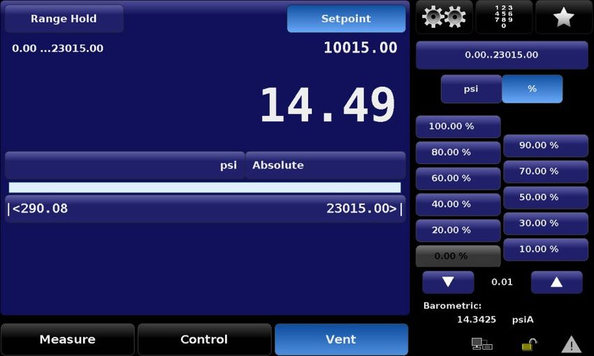
Contents

        6.1.1     Power Up  .   .   .   .   .   .   .   .   .   .   .   .   .   .   .   .   .   .   .   .   .   .   .   .   .   .   .   .   .   .   .   .   .        24
        6.1.2     Setup Applications  .   .   .   .   .   .   .   .   .   .   .   .   .   .   .   .   .   .   .   .   .   .   .   .   .   .   .   .   .   .          24
        6.1.3     Display Screen Features  .   .   .   .   .   .   .   .   .   .   .   .   .   .   .   .   .   .   .   .   .   .   .   .   .   .   .   .             24
      6.2 Initial Setup  .   .   .   .   .   .   .   .   .   .   .   .   .   .   .   .   .   .   .   .   .   .   .   .   .   .   .   .   .   .   .   .   .   .   .   25
EN      6.2.1     Information Application  .   .   .   .   .   .   .   .   .   .   .   .   .   .   .   .   .   .   .   .   .   .   .   .   .   .   .   .   .         25
        6.2.2     Language Selection   .   .   .   .   .   .   .   .   .   .   .   .   .   .   .   .   .   .   .   .   .   .   .   .   .   .   .   .   .   .         26
      6.3 Application Selection and Parameter Inputs  .   .   .   .   .   .   .   .   .   .   .   .   .   .   .   .   .   .   .   .   .   .   .   .                  26
      6.4 Applications  .  .  .  .  .  .  .  .  .  .  .  .  .  .  .  .  .  .  .  .  .  .  .  .  .  .  .  .  .  .  .  .  .  .  .                                      26
        6.4.1     Main Screen  .   .   .   .   .   .   .   .   .   .   .   .   .   .   .   .   .   .   .   .   .   .   .   .   .   .   .   .   .   .   .   .         26
          6.4.1.1      Range Hold  .   .   .   .   .   .   .   .   .   .   .   .   .   .   .   .   .   .   .   .   .   .   .   .   .   .   .   .   .   .   .         27
          6.4.1.2      Setpoint  .   .   .   .   .   .   .   .   .   .   .   .   .   .   .   .   .   .   .   .   .   .   .   .   .   .   .   .   .   .   .   .       27
          6.4.1.3      Numeric Keypad  .  .  .  .  .  .  .  .  .  .  .  .  .  .  .  .  .  .  .  .  .  .  .  .  .  .  .  .  .  .                                      28
          6.4.1.4      Number Pad Step  .  .  .  .  .  .  .  .  .  .  .  .  .  .  .  .  .  .  .  .  .  .  .  .  .  .  .  .  .                                        28
            6.4.1.4.1     Percent Step  .  .  .  .  .  .  .  .  .  .  .  .  .  .  .  .  .  .  .  .  .  .  .  .  .  .  .  .  .  .                                     29
            6.4.1.4.2     Digit Step  .  .  .  .  .  .  .  .  .  .  .  .  .  .  .  .  .  .  .  .  .  .  .  .  .  .  .  .  .  .  .                                    29
            6.4.1.4.3     Programs  .   .   .   .   .   .   .   .   .   .   .   .   .   .   .   .   .   .   .   .   .   .   .   .   .   .   .   .   .   .   .        30
          6.4.1.5      Favorites  .   .   .   .   .   .   .   .   .   .   .   .   .   .   .   .   .   .   .   .   .   .   .   .   .   .   .   .   .   .   .   .      31
          6.4.1.6      Units and Pressure Type   .   .   .   .   .   .   .   .   .   .   .   .   .   .   .   .   .   .   .   .   .   .   .   .   .   .   .           31
          6.4.1.7      Bar Graph and Control Limits  .   .   .   .   .   .   .   .   .   .   .   .   .   .   .   .   .   .   .   .   .   .   .   .   .               32
          6.4.1.8      Auxiliary Displays  .   .   .   .   .   .   .   .   .   .   .   .   .   .   .   .   .   .   .   .   .   .   .   .   .   .   .   .   .         32
          6.4.1.9      Operating Modes  .   .   .   .   .   .   .   .   .   .   .   .   .   .   .   .   .   .   .   .   .   .   .   .   .   .   .   .   .            33
            6.4.1.9.1     Measure Mode   .   .   .   .   .   .   .   .   .   .   .   .   .   .   .   .   .   .   .   .   .   .   .   .   .   .   .   .   .           33
            6.4.1.9.2     Control Mode  .   .   .   .   .   .   .   .   .   .   .   .   .   .   .   .   .   .   .   .   .   .   .   .   .   .   .   .   .            33
            6.4.1.9.3     Vent Mode  .   .   .   .   .   .   .   .   .   .   .   .   .   .   .   .   .   .   .   .   .   .   .   .   .   .   .   .   .   .           34
          6.4.1.10     Status Bar and Barometer Reading  .  .  .  .  .  .  .  .  .  .  .  .  .  .  .  .  .  .  .  .  .  .  .                                         34
        6.4.2     Settings  .  .  .  .  .  .  .  .  .  .  .  .  .  .  .  .  .  .  .  .  .  .  .  .  .  .  .  .  .  .  .  .  .  .                                     35
          6.4.2.1      General Settings  .   .   .   .   .   .   .   .   .   .   .   .   .   .   .   .   .   .   .   .   .   .   .   .   .   .   .   .   .           35
            6.4.2.1.1     Languages  .   .   .   .   .   .   .   .   .   .   .   .   .   .   .   .   .   .   .   .   .   .   .   .   .   .   .   .   .   .           35
            6.4.2.1.2     Auxiliary Displays  .  .  .  .  .  .  .  .  .  .  .  .  .  .  .  .  .  .  .  .  .  .  .  .  .  .  .  .                                     36
            6.4.2.1.3     Cal Function  .   .   .   .   .   .   .   .   .   .   .   .   .   .   .   .   .   .   .   .   .   .   .   .   .   .   .   .   .   .        36
            6.4.2.1.4     Brightness  .   .   .   .   .   .   .   .   .   .   .   .   .   .   .   .   .   .   .   .   .   .   .   .   .   .   .   .   .   .          38
            6.4.2.1.5     Volume  .  .  .  .  .  .  .  .  .  .  .  .  .  .  .  .  .  .  .  .  .  .  .  .  .  .  .  .  .  .  .  .                                     38
            6.4.2.1.6     Barometer Units  .   .   .   .   .   .   .   .   .   .   .   .   .   .   .   .   .   .   .   .   .   .   .   .   .   .   .   .             38
            6.4.2.1.7     Configurations Load/Save  .  .  .  .  .  .  .  .  .  .  .  .  .  .  .  .  .  .  .  .  .  .  .  .  .                                        39
          6.4.2.2      Sensor Settings  .   .   .   .   .   .   .   .   .   .   .   .   .   .   .   .   .   .   .   .   .   .   .   .   .   .   .   .   .   .        40
            6.4.2.2.1     Sensor Filter  .  .  .  .  .  .  .  .  .  .  .  .  .  .  .  .  .  .  .  .  .  .  .  .  .  .  .  .  .  .                                    40
            6.4.2.2.2     Sensor Resolution  .  .  .  .  .  .  .  .  .  .  .  .  .  .  .  .  .  .  .  .  .  .  .  .  .  .  .  .                                      40
            6.4.2.2.3     Units Setting  .  .  .  .  .  .  .  .  .  .  .  .  .  .  .  .  .  .  .  .  .  .  .  .  .  .  .  .  .  .                                    40
            6.4.2.2.4     User Units and Multiplier Settings  .  .  .  .  .  .  .  .  .  .  .  .  .  .  .  .  .  .  .  .  .  .  .                                    41
          6.4.2.3      Control Settings  .  .  .  .  .  .  .  .  .  .  .  .  .  .  .  .  .  .  .  .  .  .  .  .  .  .  .  .  .  .                                    41
            6.4.2.3.1     Maximum and Minimum Limits  .   .   .   .   .   .   .   .   .   .   .   .   .   .   .   .   .   .   .   .   .   .   .                      42
            6.4.2.3.2     Stable Limits and Delay   .   .   .   .   .   .   .   .   .   .   .   .   .   .   .   .   .   .   .   .   .   .   .   .   .   .            42
                                                                                                                                                                          PN 0018708001C 03/2021 EN

            6.4.2.3.3     Vent Limit  .  .  .  .  .  .  .  .  .  .  .  .  .  .  .  .  .  .  .  .  .  .  .  .  .  .  .  .  .  .  .                                    43
            6.4.2.3.4     Tank Pump  .   .   .   .   .   .   .   .   .   .   .   .   .   .   .   .   .   .   .   .   .   .   .   .   .   .   .   .   .   .           44
          6.4.2.4      Remote Settings  .   .   .   .   .   .   .   .   .   .   .   .   .   .   .   .   .   .   .   .   .   .   .   .   .   .   .   .   .            44
            6.4.2.4.1     Command Set  .  .  .  .  .  .  .  .  .  .  .  .  .  .  .  .  .  .  .  .  .  .  .  .  .  .  .  .  .                                         45
            6.4.2.4.2     Termination Character  .   .   .   .   .   .   .   .   .   .   .   .   .   .   .   .   .   .   .   .   .   .   .   .   .   .               45
            6.4.2.4.3     IEEE-488 Address  .  .  .  .  .  .  .  .  .  .  .  .  .  .  .  .  .  .  .  .  .  .  .  .  .  .  .  .                                       46
            6.4.2.4.4     Ethernet Settings  .  .  .  .  .  .  .  .  .  .  .  .  .  .  .  .  .  .  .  .  .  .  .  .  .  .  .  .                                      46
            6.4.2.4.5     Serial Settings  .  .  .  .  .  .  .  .  .  .  .  .  .  .  .  .  .  .  .  .  .  .  .  .  .  .  .  .  .                                     46

     4            WIKA operating instructions hydraulic high pressure controller, model CPC8000-H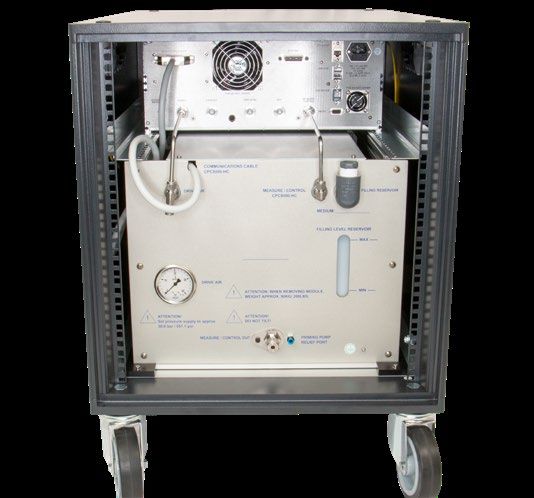
Contents
6.4.2.5 Applications Settings . . . . . . . . . . . . . . . . . . . . . . . . . . . . 47
6.4.2.5.1 Programs . . . . . . . . . . . . . . . . . . . . . . . . . . . . . . . 47
6.4.2.5.2 Favorites . . . . . . . . . . . . . . . . . . . . . . . . . . . . . . . 49
6.4.2.5.3 Troubleshooting . . . . . . . . . . . . . . . . . . . . . . . . . . . . . 49
7. Remote Operation 50 EN
7.1 Remote Operating Parameters . . . . . . . . . . . . . . . . . . . . . . . . . . . . 50
7.2 Command Set . . . . . . . . . . . . . . . . . . . . . . . . . . . . . . . . . . 50
7.3 IEEE-488 . . . . . . . . . . . . . . . . . . . . . . . . . . . . . . . . . . . . 50
7.3.1 IEEE-488.2 Commands . . . . . . . . . . . . . . . . . . . . . . . . . . . . . 50
7.4 Ethernet . . . . . . . . . . . . . . . . . . . . . . . . . . . . . . . . . . . . 50
7.5 Serial . . . . . . . . . . . . . . . . . . . . . . . . . . . . . . . . . . . . . 51
7.5.1 Serial Cable Requirements . . . . . . . . . . . . . . . . . . . . . . . . . . . 51
7.6 Mensor Command Set . . . . . . . . . . . . . . . . . . . . . . . . . . . . . . . 52
7.6.1 Command and Query Format . . . . . . . . . . . . . . . . . . . . . . . . . . . 52
7.6.2 Command Set Definitions . . . . . . . . . . . . . . . . . . . . . . . . . . . . 52
7.6.3 Output Formats . . . . . . . . . . . . . . . . . . . . . . . . . . . . . . . 52
7.6.4 Mensor Commands and Queries . . . . . . . . . . . . . . . . . . . . . . . . . 53
7.7 Wika SCPI Command Set . . . . . . . . . . . . . . . . . . . . . . . . . . . . . . 62
8. Maintenance and Recalibration 66
8.1 Admin Passwords . . . . . . . . . . . . . . . . . . . . . . . . . . . . . . . . . 66
8.2 Maintenance . . . . . . . . . . . . . . . . . . . . . . . . . . . . . . . . . . 66
8.2.1 Beyond the Warranty . . . . . . . . . . . . . . . . . . . . . . . . . . . . . . 67
8.2.2 Hydraulic Media Filling . . . . . . . . . . . . . . . . . . . . . . . . . . . . . 67
8.2.3 Transducer Removal . . . . . . . . . . . . . . . . . . . . . . . . . . . . . . 68
8.3 Recalibration . . . . . . . . . . . . . . . . . . . . . . . . . . . . . . . . . . 69
8.3.1 Calibration Services by Mensor or WIKA Worldwide . . . . . . . . . . . . . . . . . . . 69
8.3.2 Environment . . . . . . . . . . . . . . . . . . . . . . . . . . . . . . . . 70
8.3.3 Pressure Standards . . . . . . . . . . . . . . . . . . . . . . . . . . . . . . 70
8.3.4 Media . . . . . . . . . . . . . . . . . . . . . . . . . . . . . . . . . . . 70
8.3.5 Setup . . . . . . . . . . . . . . . . . . . . . . . . . . . . . . . . . . . 70
8.3.6 Calibration Data . . . . . . . . . . . . . . . . . . . . . . . . . . . . . . . 71
8.3.7 1 Point Calibration Application . . . . . . . . . . . . . . . . . . . . . . . . . . 71
8.3.8 2 Point Calibration Application . . . . . . . . . . . . . . . . . . . . . . . . . . 72
8.3.9 Linearization Application . . . . . . . . . . . . . . . . . . . . . . . . . . . . 72
9. Dismounting, Return and Disposal 74
9.1 Dismounting . . . . . . . . . . . . . . . . . . . . . . . . . . . . . . . . . . 74
9.2 Return . . . . . . . . . . . . . . . . . . . . . . . . . . . . . . . . . . . . 75
9.3 Disposal . . . . . . . . . . . . . . . . . . . . . . . . . . . . . . . . . . . . 75
10. Specifications 76
10.1 Measurement Specification . . . . . . . . . . . . . . . . . . . . . . . . . . . . . 76
10.2 Approvals and Certificates . . . . . . . . . . . . . . . . . . . . . . . . . . . . . . 78
10.3 Dimensions in mm (in) . . . . . . . . . . . . . . . . . . . . . . . . . . . . . . . 78
PN 0018708001C 03/2021 EN
10.3.1 CPC8000-H with optional rolling rack . . . . . . . . . . . . . . . . . . . . . . . . 78
10.3.2 CPC8000-HM hydraulic module . . . . . . . . . . . . . . . . . . . . . . . . . . 80
10.3.3 CPC8000-HC pneumatic controller (inches) . . . . . . . . . . . . . . . . . . . . . . 81
11. Accessories 82
11.1 Barometric Reference Sensor . . . . . . . . . . . . . . . . . . . . . . . . . . . . 82
11.1.1 Emulation Mode Accuracy . . . . . . . . . . . . . . . . . . . . . . . . . . . . 82
11.1.2 Barometric Reference Calibration . . . . . . . . . . . . . . . . . . . . . . . . . 82
WIKA operating instructions hydraulic high pressure controller model CPC8000-H 5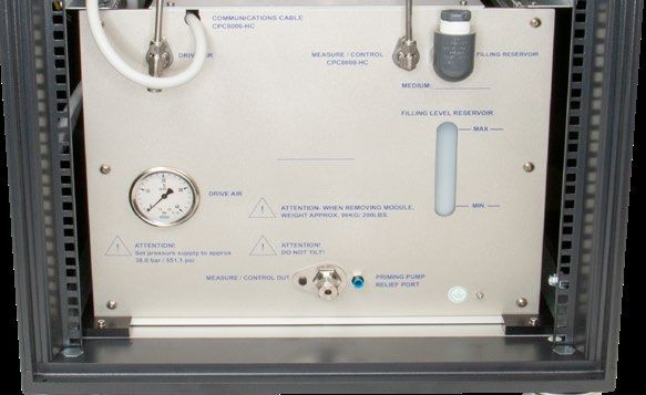
Contents

       11.2 Barometric Reference Calibration Sled  .   .   .   .   .   .   .   .   .   .   .   .   .   .   .   .   .   .   .   .   .   .   .   .   .          82
       11.3 Reference Pressure Calibration Sled .   .   .   .   .   .   .   .   .   .   .   .   .   .   .   .   .   .   .   .   .   .   .   .   .   .         82
         11.3.1  CPR8000 Reference Calibration Sled   .   .   .   .   .   .   .   .   .   .   .   .   .   .   .   .   .   .   .   .   .   .   .   .           83
         11.3.2  CPR8050 and CPR8850 reference pressure calibration sled  .  .  .  .  .  .  .  .  .  .  .  .  .  .  .  .                                      83
EN     11.4 Operating fluid  .  .  .  .  .  .  .  .  .  .  .  .  .  .  .  .  .  .  .  .  .  .  .  .  .  .  .  .  .  .  .  .  .  .                             83
     12. Appendix                                                                                                                                             84
       12.1 Measurement Units  .  .  .  .  .  .  .  .  .  .  .  .  .  .  .  .  .  .  .  .  .  .  .  .  .  .  .  .  .  .  .  .                                 84
       12.2 Conversion Factors, PSI  .   .   .   .   .   .   .   .   .   .   .   .   .   .   .   .   .   .   .   .   .   .   .   .   .   .   .   .   .   .    85

     Declarations of conformity can be found online at www.wika.com.
                                                                                                                                                                   PN 0018708001C 03/2021 EN

      6            WIKA operating instructions hydraulic high pressure controller, model CPC8000-H
1. General information

                            1. General Information
                            ■ The CPC8000-H hydraulic high pressure controller described in the operating instructions has been designed and
                              manufactured using state-of-the-art technology. All components are subject to stringent quality and environmental criteria during
                              production. Our management systems are certified to ISO 9001 and ISO 14001.                                                           EN
                            ■ These operating instructions contain important information on handling the instrument. Working safely requires that all safety
                              instructions and work instructions are observed.

                            ■ Observe the relevant local accident prevention regulations and general safety regulations for the instrument's operating range.

                            ■ The operating instructions are part of the instrument and must be kept in the immediate vicinity of the instrument and readily
                              accessible to skilled personnel at any time. Pass the operating instructions onto the next operator or owner of the instrument.

                            ■ Skilled personnel must have carefully read and understood the operating instructions prior to beginning any work.

                            ■ The general terms and conditions contained in the sales documentation shall apply.

                            ■ Subject to technical modifications.

                            ■ Factory calibrations / A2LA / DKD/DAkkS calibrations are carried out in accordance with international standards.

                            ■ Further information:

                            Mensor Corporation
                            - Address                            201 Barnes Dr., San Marcos, TX 78666
                            - Internet address:                  www.mensor.com
                            - Relevant data sheet:               CT 32.05
                            - Application consultant:            Tel.: (+1) 512-396-4200
                                                                       (+1) 800-984-4200 (USA only)
                                                                 Fax: (+1) 512-396-1820
                                                                 E-Mail: sales@mensor.com
                                                                 techservices@mensor.com
                                Importer for Europe
                                WIKA Alexander Wiegand SE & Co. KG
                                                                    Alexander Wiegand-Straße
                                - Address
                                                                    63911 Klingenberg, Germany
                                - Internet address:                 www.wika.de / www.wika.com
                                - Relevant data sheet:              CT 32.05
                                - Application consultant:           Tel.: (+49) 9372/132-5015
                                                                    Fax: (+49) 9372/132-8767
                                                                    E-Mail: CTsales@wika.com
PN 0018708001C 03/2021 EN

                             WIKA operating instructions hydraulic high pressure controller model CPC8000-H                                                     7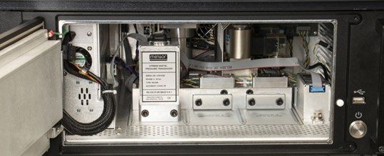
1. General Information

     1.1 Warranty
     All products manufactured by Mensor are warranted to be free of defects in workmanship and materials for a period of two years
     from the date of shipment. No other express warranty is given, and no affirmation of Seller, by words or actions, shall constitute
     a warranty. SELLER DISCLAIMS ANY IMPLIED WARRANTIES OF MERCHANTABILITY OR FITNESS FOR ANY PARTICULAR
EN   PURPOSES WHATSOEVER. If any defect in workmanship or material should develop under conditions of normal use and service
     within the warranty period, repairs will be made at no charge to the original purchaser, upon delivery of the product(s) to the
     factory, shipping charges prepaid. If inspection by Mensor or its authorized representative reveals that the product was damaged
     by accident, alteration, misuse, abuse, faulty installation or other causes beyond the control of Mensor, this warranty does not
     apply. The judgment of Mensor will be final as to all matters concerning condition of the product, the cause and nature of a defect,
     and the necessity or manner of repair. Service, repairs or disassembly of the product in any manner, performed without specific
     factory permission, voids this warranty.

     MENSOR MAKES NO WARRANTY OF ANY KIND WITH REGARD TO THIS MANUAL, INCLUDING, BUT NOT LIMITED TO, THE
     IMPLIED WARRANTIES OF MERCHANTABILITY AND FITNESS FOR A PARTICULAR PURPOSE. Mensor shall not be liable for
     errors contained herein or for incidental or consequential damages in connection with the furnishing, performance, or use of this
     material.

     1.2   Radio Frequency Emission Notices

                   USE SHIELDED CABLES TO CONNECT EXTERNAL DEVICES TO THIS INSTRUMENT TO
                   MINIMIZE RF RADIATION

     1.2.1 FCC Emission Notice
     This equipment has been tested and found to comply with the limits for a Class A digital device, pursuant to part 15 of the FCC
     Rules. These limits are designed to provide reasonable protection against harmful interference when the equipment is operated in
     a commercial environment. This equipment generates, uses, and can radiate radio frequency energy and, if not installed and used
     in accordance with the instruction manual, may cause harmful interference to radio communications. Operation of this equipment
     in a residential area is likely to cause harmful interference in which case the user will be required to correct the interference at his
     or her own expense.

     1.2.2 CE Emission Notice
     This equipment is of the emission class A, intended for operation in industrial environments. It can cause interference under certain
     circumstances if operated in other environments, i.e. residential or commercial areas. In this case, the user may be asked to take
     appropriate measures to correct it.

     1.3 Software License Agreement
     This product contains intellectual property, i.e. software programs, that are licensed for use by the end user/customer (hereinafter
     “end user”).
     This is not a sale of such intellectual property.
     The end user shall not copy, disassemble or reverse compile the software program.

                   The software programs are provided to the end user “as is” without warranty of any kind, either express
                   or implied, including, but not limited to, warranties of merchantability and fitness for a particular purpose.
                   The entire risk of the quality and performance of the software program is with the end user.
                                                                                                                                                PN 0018708001C 03/2021 EN

     Mensor and its suppliers shall not be held to any liability for any damages suffered or incurred by the end user (including, but
     not limited to, general, special, consequential or incidental damages including damages for loss of business profits, business
     interruption, loss of business information and the like), arising from or in connection with the delivery, use or performance of the
     software program.

      8          WIKA operating instructions hydraulic high pressure controller, model CPC8000-H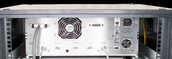
1. General Information

                            1.4 Mensor Service Plus
                            1.4.1 After the Warranty
                            Mensor’s concern with the performance of this instrument is not limited to the warranty period. We provide complete repair,
                            calibration and certification services after the warranty for a nominal fee.
                                                                                                                                                                 EN
                            1.4.2 Calibration Services
                            In addition to servicing our own products Mensor can perform a complete pressure calibration service, up to 30,000 psi, for all of
                            your pressure instruments. This service includes an accredited calibration.

                            1.4.3 Certifications and Accreditations
                            Mensor is registered to ISO 9001:2015. The calibration program at Mensor is accredited by A2LA, as complying with both the ISO/
                            IEC 17025:2017 and the ANSI/NCSL Z540-1-1994 standards.
PN 0018708001C 03/2021 EN

                             WIKA operating instructions hydraulic high pressure controller model CPC8000-H                                                  9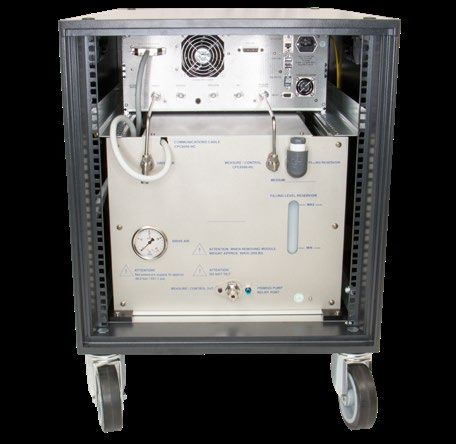
2. Short Overview

     2. Short Overview

     The CPC8000-H hydraulic high pressure controller is a multi-range automatic pressure controller designed to test and calibrate
     a variety of pressure devices such as pressure gauges, pressure switches, sensors, transducers and transmitters. It can have
EN   up to two internal pressure reference transducers and an optional barometric reference for gauge or absolute emulation. The
     CPC8000-H works with a supply pressure of nitrogen or dry, clean air and uses an intensifier assembly to convert this force to
     hydraulic pressure. It comes in two different versions, the CPC8000-H-LP, which has a 1:20 pneumatic to hydraulic ratio, and the
     CPC8000-H-MP, which has a 1:56 ratio.

                                                    Figure 2.1 CPC8000-H with Rolling Rack

     2.1 Features
     Here is a short list of significant features designed into the CPC8000-H:

     ■ Optional 19" rack cabinet with casters

     ■ Operating range from 0… 700 bar (0 … 10,000 psi) for CPC8000-H-LP and 0 .... 1,600 bar (23,000 psi) for CPC8000-H-MP

     ■ Two removable transducers with up to 0.01%FS measurement accuracy

     ■ An optional removable / interchangeable internal high accuracy barometric reference transducer providing emulation for both
       absolute and gauge pressure ranges

     ■ 9” color LCD with touch screen

     ■ Ethernet, RS-232, USB and IEEE-488 communications
                                                                                                                                        PN 0018708001C 03/2021 EN

     ■ Multiple languages; change the language for on-screen text and number/date formats by simply touching one of the “national
       flag” icons available in the setup screen.

     ■ Multiple media capabilities. (Oil, water, and a variety of others upon request)

      10         WIKA operating instructions hydraulic high pressure controller, model CPC8000-H
2. Short overview
2.2 Components
2.2.1 CPC8000-HC pneumatic pressure controller
The CPC8000-HC is composed of:
■ A CPC8000 pnuematic pressure controller
■ A 35 bar (508 psi) gauge pilot transducer EN
■ Optional internal barometric reference transducer
■ Touchscreen interface for local operation
■ Communication ports on rear panel for remote operation
■ Programmable sequences for automated calibration
Pilot Transducer
Optional barometric
reference
Figure 2.2.1 CPC8000-HC 1
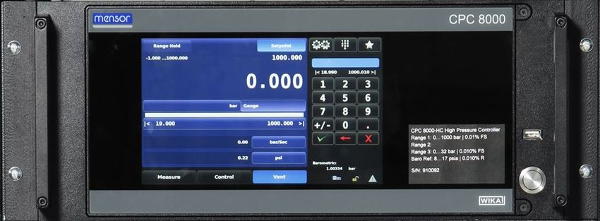
2.2.2 CPC8000-HM hydraulic module
The CPC8000-HM is the housing for the intensifiers and reference pressure transducers. This module consists of:
■ Two intensifiers working in parallel for quick control and larger volumes
■ Priming pump to ensure the DUT and intensifiers are purged
■ Media reservoir tank with sight glass for maintaining an optimal fluid level
■ Filling nozzle for easy refilling of the hydraulic media. (Sebacate, Shell Tellus and distilled water. Consult factory for other media)
PN 0018708001C 03/2021 EN
Figure 2.2.2 CPC8000-HM
2.3 Turning On
Apply power to the power connector on the rear panel of the CPC8000-HC with the included power cord and press the power
switch to ON. The system will go through an initialization process, which takes about 1 minute, and then a display will appear
similar to the screen shown below. The instrument must be powered on for a minimum of 60 minutes to allow for best system
accuracy.
WIKA operating instructions hydraulic high pressure controller model CPC8000-H 112. Short overview
EN
Power Switch ON/
OFF
Figure 2.3 Power Button
Earth Ground! Any power adapters or surge protection devices that negate the protective earth ground
should not be used. The power cord must be accessible and contain a protective earth ground. Do not
position the equipment so that it is difficult to remove the power cord.
To see information about the configuration of your new CPC8000-H, touch the Info button under the settings menu and a window
will appear listing the Mensor contact information, model number and the transducers that are installed. Press the back arrow to
return to the Home screen.
Figure 2.3 Information application
2.4 Front Panel
The CPC8000-H front panel includes a 9” color LCD display with touch screen. Operator input is accomplished by pressing the
words or symbols and the icons presented on the display. There is a single discrete on/off button and a USB port on the right hand
side. The front panel also shows the model number designation, pressure ranges and brand logos.
PN 0018708001C 03/2021 EN
2.4.1 Power Switch
The power switch is a two-state device with an action similar to that of a ball point pen. Push the button with enough force to latch it
in to turn the unit ON. Push it again to release it to turn the system OFF.
If power to the instrument is interrupted while ON it will shut down until the power is restored, then
immediately resume operation.
2.4.2 USB Port
The front panel USB port is the Host USB and is intended for software upgrades. Section 6 Operation explains this in detail.
12 WIKA operating instructions hydraulic high pressure controller, model CPC8000-H2. Short overview
2.5 Display
The display is made up of two sections. In the main screen, the left two thirds shows the operating screen displaying the active
pressure reading, units, mode (absolute or gauge), setpoint, bar graph (if enabled), zero button (if enabled), tare button (if
enabled), and up to two auxiliary displays that are user selectable. At the bottom of this section are three control modes: Measure,
Control and Vent. The right one third of the screen has the Settings button, Keypad button and Favorites button. The Settings EN
button will take the user to a new screen with all the setting applications. The Keypad button will display a numberpad with all the
buttons needed to input values. The Favorites button will display the sequences that have been set up as favorites by the user. On
the bottom of this section is the optional barometric pressure reading, and remote and troubleshooting alerts.
Active Transducer
Optional Zero or Tare
Current Pressure
Units and Mode
Optional Bar Graph
Auxiliary Displays
{
Operating Modes
Operating Screen Data entry
Buttons, Labels and Windows: The CPC8000-H touch screen has many buttons with relevant graphic icons or text which,
when touched, will open a related window where changes can be made or information viewed. Some of these buttons will toggle
from one state to another, others present choices or display a numerical data entry screen. Text or icons that are displayed, but
do not respond to being touched, are called labels or windows. Operators will quickly become accustomed to the particular
characteristics of the frequently used buttons.
Main Screen: The main screen appears after power-up. It will remain as configured after a power cycle.
Operating screen: The operating screen (left 2/3 of the main screen) contains information relevant to the pressure measurement.
Up to two auxiliary displays can be shown simultaneously along with the current pressure value
2.6 Scope of Delivery
■ Hydraulic high pressure controller, model CPC8000-H
■ Power cord with 1.5 m (5 ft) length
■ Operating instructions
■ Factory calibration certificate
■ 1/4" Sno-Trik nut and ferrules for the Measure port
PN 0018708001C 03/2021 EN
■ 6mm to 1/4" adapter for supply port
Cross-check scope of delivery with delivery note.
WIKA operating instructions hydraulic high pressure controller model CPC8000-H 133. Safety
3. Safety
3.1 Explanation of Symbols
DANGER!
EN ... indicates a directly dangerous situation resulting in serious injury or death, if not avoided.
WARNING!
... indicates a potentially dangerous situation that can result in serious injury or death, if not avoided.
CAUTION!
... indicates a potentially dangerous situation that can result in light injuries or damage to property or the environment,
if not avoided.
DANGER!
... identifies hazards caused by electrical power. Should the safety instructions not be observed, there is a risk of
serious or fatal injury.
WARNING!
... indicates a potentially dangerous situation that can result in burns, caused by hot surfaces or liquids, if not avoided.
Information
... points out useful tips, recommendations and information for efficient and trouble-free operation.
3.2 Intended Use
The CPC8000-H hydraulic high pressure controller is designed to automate the testing and calibration of pressure devices and
instruments for pressures up to 1,600 bar or 23,000 psi. Up to two removable/interchangeable pressure transducers are available
in full scale (FS) ranges from 1,500 to 23,000 psi (100 to 1600 bar). Each transducer is configured with its own calibration
parameters on board. Accuracies are available with 0.01 up to 10,000 psi and 0.014 up to 23,000 psi. In addition to the two active
range transducers, a barometric reference is also available as an option. With this option enabled, the CPC8000-H can emulate
both gauge and absolute pressures. The CPC8000-H requires a pneumatic supply pressure of 35 bar which it uses to control the
hydraulic pressure output through an intensifier mechanism. The CPC8000 uses a 35 bar pneumatic transducer to monitor this
pilot pressure.
This instrument is not permitted to be used in hazardous areas!
The instrument has been designed and built solely for the intended use described here, and may only be used accordingly.
The technical specifications contained in these operating instructions must be observed. Improper handling or operation of the
instrument outside of its technical specifications requires the instrument to be taken out of service immediately and inspected by
PN 0018708001C 03/2021 EN
an authorized WIKA/Mensor service engineer.
Handle electronic precision measuring instruments with the required care (protect from humidity, impacts, strong magnetic fields,
static electricity and extreme temperatures, do not insert any objects into the instrument or its openings). Plugs and sockets must
be protected from contamination.
The manufacturer shall not be liable for claims of any type based on operation contrary to the intended use.
14 WIKA operating instructions hydraulic high pressure controller, model CPC8000-H3. Safety
3.3 Improper Use
WARNING!
Injuries through improper use
Improper use of the instrument can lead to hazardous situations and injuries. EN
▶ Refrain from unauthorized modifications to the instrument.
▶ Do not use the instrument within hazardous areas.
▶ Use only hydraulic media specified in user manual. (Consult factory for non-specified media)
Any use beyond or different to the intended use is considered as improper use. Do not use this instrument in safety or emergency
stop devices.
3.4 Responsibility of the Operator
The instrument is used in the industrial sector. The operator is therefore responsible for legal obligations regarding safety at work.
The safety instructions within these operating instructions, as well as the safety, accident prevention and environmental protection
regulations for the application area must be maintained.
The operator is obliged to maintain the product label in a legible condition.
To ensure safe working on the instrument, the operating company must ensure that
■ suitable first-aid equipment is available and aid is provided whenever required.
■ the operating personnel are regularly instructed in all topics regarding work safety, first aid and environmental protection and
know the operating instructions and in particular, the safety instructions contained therein.
■ the instrument is suitable for the particular application in accordance with its intended use.
■ personal protective equipment is available.
3.5 Personnel Qualification
WARNING!
Risk of injury should qualification be insufficient
Improper handling can result in considerable injury and damage to equipment.
▶ The activities described in these operating instructions may only be carried out by skilled personnel who have the
qualifications described below.
Skilled personnel
Skilled personnel, authorized by the operator, are understood to be personnel who, based on their technical training, knowledge
of measurement and control technology and on their experience and knowledge of country-specific regulations, current standards
and directives, are capable of carrying out the work described and independently recognizing potential hazards.
Operating personnel
The personnel trained by the operator are understood to be personnel who, based on their education, knowledge and experience,
are capable of carrying out the work described and independently recognizing potential hazards.
Special knowledge for working with instruments for hazardous areas:
PN 0018708001C 03/2021 EN
The skilled (electrical) personnel must have knowledge of ignition protection types, regulations and provisions for equipment in
hazardous areas.
Special operating conditions require further appropriate knowledge, e.g. of aggressive media.
WIKA operating instructions hydraulic high pressure controller model CPC8000-H 153. Safety
3.6 Personal Protective Equipment
The personal protective equipment is designed to protect the skilled personnel from hazards that could impair their safety or health
during work. When carrying out the various tasks on and with the instrument, the skilled personnel must wear personal protective
equipment.
EN
Follow the instructions displayed in the work area regarding personal protective equipment!
The requisite personal protective equipment must be provided by the operating company.
Wear clean and protective safety glasses!
3.7 Labeling, Safety Marks
3.7.1 Product Label
1
2
3
4
5
6
1 Model 4 Power supply
2 Serial number 5 Power consumption
3 Date of manufacturing 6 Fuse
3.7.2 Symbols
Before mounting and commissioning the instrument, ensure you read the operating instructions!
CE, Communauté Européenne
Instruments bearing this mark comply with the relevant European directives.
PN 0018708001C 03/2021 EN
This marking on the instruments indicates that they must not be disposed of in domestic waste. The disposal is
carried out by return to the manufacturer or by the corresponding municipal authorities (see EU directive 2012/19/
EU).
3.8 Warnings and Cautions
16 WIKA operating instructions hydraulic high pressure controller, model CPC8000-H3. Safety
WARNING!
HIGH PRESSURE! High pressure liquids and gases are potentially hazardous. Energy stored in these gases and
liquids can be released suddenly and with extreme force. High pressure systems should be assembled and operated
only by personnel who have been trained in proper safety practices. EN
WARNING!
NOT EXPLOSION PROOF! Installation of this instrument in an area requiring devices rated as intrinsically safe is not
recommended.
WARNING!
POSSIBLE INJURY! The tubing, valves, and other apparatus attached to the controller must be adequate for the
maximum pressure which will be applied, otherwise physical injury to the operator or bystanders is possible.
CAUTION
USE THE PROPER PRESSURE MEDIUM! Use only clean, dry air or nitrogen for the CPC8000-HC and only
specified medium on the CPC8000-HM unless otherwise specified by Mensor.
CAUTION
As with most sensitive electronic equipment, switch the power switch off before connecting or disconnecting to a
power source to prevent data loss. Do not position the equipment so that it is difficult to disconnect the AC power
cord.
WARNING!
Use the originally delivered power supply cord only! If not possible, contact us or use a certified power cord with
ratings according to Section 10. Specifications for power ratings.
WARNING!
POSSIBLE INJURY! Personnel shoudl not be in close proximity to the vent port during venting.
Additional Warning and Caution notices are found throughout this manual.
PN 0018708001C 03/2021 EN
WIKA operating instructions hydraulic high pressure controller model CPC8000-H 174. Transport, Packaging and Storage
4. Transport, Packaging and Storage
4.1 Transport
Check the hydraulic high pressure controller CPC8000-H for any damage that may have been caused by transport.
EN Obvious damage must be reported immediately.
CAUTION!
Damage through improper transport
With improper transport, a high level of damage to property can occur.
▶ When unloading packed goods upon delivery as well as during internal transport, proceed carefully and observe
the symbols on the packaging.
▶ With internal transport, observe the instructions in chapter 4.2 “Packaging and storage”.
WARNING!
Physical injuries to personnel caused by heavy weight
Carefully follow all transport, packaging and storage instructions to prevent injuries caused by the weight of the
CPC8000-H.
If the instrument is transported from a cold into a warm environment, the formation of condensation may result in instrument
malfunction. Before putting it back into operation, wait for the instrument temperature and the room temperature to equalize.
4.2 Packaging and storage
The CPC8000-H is packaged inside a custom crate and strapped down to a pallet.
Keep the packaging, as it will provide optimum protection during transport (e.g. change in installation site, sending for repair).
Permissible conditions at the place of storage:
■ Storage temperature: 5 ... 70 °C
■ Humidity: 0 ... 95 % relative humidity (no condensation)
Avoid exposure to the following factors:
■ Direct sunlight or proximity to hot objects
■ Mechanical vibration, mechanical shock (putting it down hard)
■ Soot, vapor, dust and corrosive gases
■ Hazardous environments, flammable atmospheres
■ Direct exposure to air vent
PN 0018708001C 03/2021 EN
18 WIKA operating instructions hydraulic high pressure controller, model CPC8000-H5. Installation
5. Installation
Personnel: Skilled electrical and mechanical personnel
The following instructions must be followed in setting up the instrument for the first and any time after transporting to a different
location EN
WARNING!
READ THESE INSTRUCTIONS BEFORE INSTALLATION!
WARNING!
Physical injuries and damage to property and the environment caused by hazardous media
Upon contact with hazardous media (e.g. oxygen, acetylene, flammable or toxic substances), harmful media (e.g.
corrosive, toxic, carcinogenic, radioactive), and also with refrigeration plants and compressors, there is a danger of
physical injuries and damage to property and the environment.
Should a failure occur, aggressive media with extremely high temperature and under high pressure may be present
at the instrument.
▶ For these media, in addition to all standard regulations, the appropriate existing codes or regulations must also be
followed.
▶ Wear the requisite protective equipment (see chapter 3.6 “Personal protective equipment”).
CAUTION
Damage to the instrument
When working on open electrical circuits (printed circuit boards) there is a risk of damaging sensitive electronic
components through electrostatic discharge.
▶ The correct use of grounded working surfaces and personal armbands is required.
5.1 Mounting
If ordered without a rolling rack and casters, it should be installed on a stable surface. Avoid mounting the insturment on surfaces
subject to motor or machinery vibration and far away from doors, windows, heating systems and air conditioning vents. The
CPC8000-H can optionally be installed in a rack with casters. It should be stationed away from any vibrations and changing air
flow and the casters should be locked into place.
CAUTION
Avoid any vibrations and direct solar rays. Any significant temperature fluctuations can make the
instrument unstable. Do not use the CPC8000-H in explosive atmospheres, permanently humid or dusty
environments.
5.2 Rear Panel
The complete rear panel of the CPC8000-H consists of two independent modules, the CPC8000-HC pneumatic module and the
CPC8000-HM hydraulic module. There are a total of 9 pressure ports, 6 communication ports, and a power inlet.
5.2.1 Pressure ports
WARNING!
All pressure ports should be vented before disconnected.
PN 0018708001C 03/2021 EN
While changing any pressure port on the CPC8000-H, the pressure should be fully vented and the source should be
turned off.
WARNING!
Use the proper equipment and tooling for pressure connections.
Ensure that all tooling and process connections are appropriate for the pressure connection. Never use the wrong
connector or tool while fastening a pressure port fitting or connector.
WIKA operating instructions hydraulic high pressure controller model CPC8000-H 195. Installation
5.2.1.1 CPC8000-HC
The CPC8000-HC module has 6 pressure ports: barometric reference, supply, exhaust, vent, reference, and measure/control port.
• The barometric reference port uses a barb fitting with a 10-32 unf thread. This port is used to monitor atmospheric pressure
EN when the optional barometric reference transducer is installed.
• The supply port uses a 7/16" SAE female thread. This port is required to have approximately 100 to 110 % of the pilot pressure
range: 35 bar.
• The exhaust port uses a 7/16" SAE female thread. This port is not used in the CPC8000-H model.
• The vent port uses a 7/16" SAE female thread. This port is used during control and vent mode to relieve pressure from the
instrument.
• The reference port uses a 7/16" SAE female thread. This port is not used in the CPC8000-H model.
• The measure/control port uses a 7/16" SAE female thread. This port is used to link the CPC8000-HC to the hydraulic module.
This provides the air supply to the intensifier while in control mode.
Barometric
Reference
Exhaust `Vent Reference Measure/Control
Supply
5.2.1.2 CPC8000-HM
The CPC8000-HM contains 3 ports: the drive air, measure/control CPC8000-HC, and measure/control DUT.
• The pneumatic supply pressure uses a male 6mm tube fitting. This port requires at least 8 bar (115 psi) of pressure, but it can
also use up to the full supply pressure of the CPC8000-HC. This pressure is used to actuate the isolation valves and priming
pump located within the hydraulic module.
• The measure/control CPC8000-HC port uses a male 6mm tube fitting. This port must be connected to the CPC8000-HC
measure/control port. It is used to supply air pressure to the intensifiers using the provided tubing.
• The measure/control DUT port uses a male 1/4" Sno-Trik fitting. Consult factory for different adapters. This port is used to
control hydraulic pressure on the DUT.
Measure/
Control from
Supply pressure
CPC80000-HC
Measure/
Control DUT
PN 0018708001C 03/2021 EN
WARNING!
Do not use the instrument without the Measure/Control port connected.
Be sure to always have the Measure/Control port connected to a test sample while using the CPC8000-H. If the test
port is left open or disconnected, liquid can leak from the instrument.
20 WIKA operating instructions hydraulic high pressure controller, model CPC8000-HWARNING!
Never disconnect test ports while pressurized!
Be sure the instrument is fully vented and the source pressure is turned off while disconnecting connections and
hoses from the Measure/Control port. Failure to disassemble the test ports correctly could result in leaking liquids
and gasses. EN
WARNING!
Do not exceed the maximum source pressure!
The supply pressure port is limited to 110%% over the primary pilot transducer range. Do not exceed this pressure
rating labeled on the back of the instrument.
5.2.2 Communication ports
The CPC8000-H has 6 communication ports, all located on the CPC8000-HC: IEEE-488, USB device, RS-232, Ethernet, USB host
and an interface port to communicate between the two modules. See section 8, Remote Operation, for connections and
commands for operation over IEEE-488, Ethernet, USB or RS232 ports.
5.2.2.1 USB host
The USB host port is intended for future expansions or software upgrades. This port can also be accessed through the front panel.
5.2.2.2 Interface port
The interface port is a direct communication between the CPC8000-HC module and the CPC8000-HM. This provides the
feedback information from the hydraulic module transducers. The interface cable is permanently fixed to the CPC8000-HM and
can be removed from the CPC8000-HC using a slotted screwdriver.
5.2.3 Power inlet
Apply power with the included power cable to the rear power inlet port on the CPC8000-HC. This port is equiped with two 2.5 amp
250V Slo-Blo fuses and is rated at 100 - 120 VAC or 200 - 240 VAC at 50 / 60 Hz.
Power Inlet
PN 0018708001C 03/2021 EN
Figure 5.2.3 Power Inlet
DANGER!
Use caution when dealing with power cable and inlet connection. Hazard of electric shock: warning notice according
to IEC 61010-1.
WIKA operating instructions hydraulic high pressure controller model CPC8000-H 215.2.4 Measure/Control test port prefilling
The Device Under Test must be filled with the hydraulic media to perform to the rated specifications. If there is not an designed
user designed method to prefill the DUT, the following method may be used.
1. Install the test device and tubing to the Measure/Control port of the CPC8000-H.
EN 2. Loosen a fitting furthest away from the CPC8000-H Measure/Control port.
3. Power the CPC8000-H instrument on and connect pressure to the Supply port.
4. Enter the lowest setpoint available and press Control. This will begin the priming sequence in the CPC8000-H.
5. A mixture of air and liquid will leak out of the loosened fitting.
6. Once the air is released from the system, a steady stream of liquid should appear at the loosened fitting.
7. Tighten the fitting and place the instrument in Vent mode.
8. Enter the maximum CPC8000-H primary range or the DUT maximum range, whichever is lower and confirm that the
CPC8000-H can control to the maximum pressure.
9. If the controller fails to reach the maximum pressure, there may be a leak or more trapped air in the system.
10. Repeat steps 2-7 if you suspect more air is trapped in the system.
PN 0018708001C 03/2021 EN
22 WIKA operating instructions hydraulic high pressure controller, model CPC8000-HEN
PN 0018708001C 03/2021 EN
WIKA operating instructions hydraulic high pressure controller model CPC8000-H 236. Operation
6. Operation
6.1 General Operation
This section describes the procedures for operating the CPC8000-H from the front panel. Instructions for operating the device
EN remotely from an external computer are covered in Section 8, Remote Operations. By following the procedures provided in these
two sections and section 9.2, Recalibration, you can expect your CPC8000-H to deliver maximum accuracy and dependability for
many years of useful service.
6.1.1 Power Up
Apply power to the power connector on the rear of the instrument using the power cord included, and switch the power switch on
the front of the unit ON. The instrument will go through an initialization process and system check. As soon as the system check is
completed the system will default to a screen similar to the one shown in Section 6.1.3 Display Screen Features. The main screen
may be configured in many different ways but initially it will be in a default configuration. Subsequently, the unit will power up in the
configuration that it was in when last powered off.
WARNING!
Allow 60 minutes of warm up before performing critical pressure measurements.
WARNING!
Do not position the equipment so that it is difficult to remove the power cord. The instrument is not
intended for connection of long-distance lines, i.e. lines within a building that are longer than 30 m, or that
leave the building (including lines of outdoor installations).
6.1.2 Setup Applications
Configuration of the CPC8000-H is achieved by changing settings accessed through the Application (“App”) buttons. Local
operation is accomplished by observing the data presented in the display. The appearance and functionality of the display can be
changed by pressing the App button for the related function. After an App has been chosen, a set of related parameters will appear
on the left. After choosing one of these parameters, a set of selections related to that parameter will appear on the right or a data
entry keypad. The desired selection or data can be entered here.
6.1.3 Display Screen Features
The screen shown below provides an overview of the features that may appear on the display after initialization. The left two thirds
of the display contains the area where information is displayed (in this case the Home Application) and the right one third contains
the selection icons for each application. A tare button, zero button, bar graph and up to two of the available auxiliary displays
(Peak, Rate, Sensor 3, Units, Tare, Uncertainty) will appear in the Home App, if activated. All of the CPC8000-H screen features
are described in more detail throughout this manual. Any button activated will turn a different shade of blue.
PN 0018708001C 03/2021 EN
24 WIKA operating instructions hydraulic high pressure controller, model CPC8000-H6. Operation
Active Transducer
Optional Zero or Tare
Current Pressure
EN
Units and Mode
Optional Bar Graph
Auxiliary Displays
{
Operating Modes
Operating Screen Data Entry
Figure 6.1.3 Display
6.2 Initial Setup
Section 6.2.1 and 6.2.2 are provided first so that the operator can initially check the information screen to verify the installed
components and to change the language if needed.
6.2.1 Information Application
Select the Settings application on the top right of the screen and navigate to the information application. The information tab
will contain the Mensor contact, installed transducers, installed regulator along with instrument and software version information.
PN 0018708001C 03/2021 EN
Figure 6.2.1 Information Screen
WIKA operating instructions hydraulic high pressure controller model CPC8000-H 256. Operation
6.2.2 Language Selection
Pressing the Settings button and navigating to the General tab, will display the options for Language, Secondary Display,
Tertiary Display, Cal Function, Brightness, Volume, Barometer (optional), Load and Save. The language selections available are
shown in the column on the right and the active language will be highlighted blue.
EN
Figure 6.2.2 Language Selection
6.3 Application Selection and Parameter Inputs
The data entry section on the right third of the screen (see figure 6.1.3 Display Screen Features) is the area where Settings,
Keypad or Favorites can be chosen. Selecting the Settings button will display the settings application with General, Sensor,
Control, Remote, Applications, and Information tabs. Selecting the Keypad button will display options for a Number Pad, Number
Pad Step, Percent Step, Digital Step, and Programs. Selecting the Favorites button will display a list of sequences that have been
saved in Favorites in the Application tab.
6.4 Applications
6.4.1 Main Screen
The main screen is the normal operation screen. This application is used to monitor and control pressure, run sequences, select
ranges, select units, observe auxiliary values, choose setpoints, and optionally emulate pressure types. Figure 6.4.1-A shows the
basic main screen. Figure 6.4.1-B shows the main screen with auxiliary and autozero options enabled. Figure 6.4.1-C shows the
main screen with the units button selected.
PN 0018708001C 03/2021 EN
Figure 6.4.1-A Main Screen
26 WIKA operating instructions hydraulic high pressure controller, model CPC8000-H6. Operation
EN
Figure 6.4.1-B Main Screen w/Auxiliary Figure 6.4.1-C Main Screen Units
6.4.1.1 Range Hold
The Range Hold button allows the user to select the active range transducer from a list of installed transducers. By clicking Range
Hold, the user can select the active transducer from the primary and optional secondary transducer. The instrument must be fully
vented in order to switch between ranges. The primary range will always be listed on top and the secondary range will be beneath.
Range Hold
Figure 6.4.1.1 Range Hold
6.4.1.2 Setpoint
By default, the Setpoint button is enabled on the screen with a keypad accessible on the right third(Figure 6.4.1.2-B). The Setpoint
button allows the user to enter the desired pressure value within the range of the transducers and module inside the instrument.
There are multiple ways of entering the control setpoint: numeric keypad, number pad step, percentage step, digit step or a
program. These methods can be accessed by pressing the keypad button on the top right of the screen(Figure 6.4.1.2-A).
PN 0018708001C 03/2021 EN
Figure 6.4.1.2 Keypad Options
WIKA operating instructions hydraulic high pressure controller model CPC8000-H 276. Operation
EN
Figure 6.4.1.2-B Setpoint
6.4.1.3 Numeric Keypad
The default entry method provides 10 digits for numeric entry, plus the decimal point and sign key (Figure 6.4.1.3). Each key that is
pressed will display in the blue text box directly above the keypad. The sign key will allow the user to toggle between positive
and negative values. This key can be selected at any point while entering a number. Once the desired value is entered in the blue
text box, the check button can be pressed to change the setpoint to this value. If the value is outside of the setpoint minimum
or maximum limits, directly beneath the blue text box, the numbers will turn red and the setpoint change will not be accepted. To
clear an entry, select the cancel button and the blue text box will be reset. The backspace button is used to clear the last
character that was entered.
Figure 6.4.1.3 Keypad
6.4.1.4 Number Pad Step
PN 0018708001C 03/2021 EN
The number pad step method provides the same keys as the numeric keypad and also includes up and down buttons for quick
and easy setpoint changes. The number between the two arrows shows the value that will be added or subtracted from the current
setpoint when an arrow is pressed. The Up button increases and the Down button decreases the current setpoint by the
digital step value. The digital step value can be changed by entering a number using the numeric keypad and selecting either the
Up or Down button. The setpoint in Figure 6.4.1.4 will change by 14.5 psi each time the Up or Down button is pressed. v
28 WIKA operating instructions hydraulic high pressure controller, model CPC8000-H6. Operation
EN
Figure 6.4.1.4 Number Pad
6.4.1.4.1 Percent Step
The Percent Step entry method allows the user to select setpoints based on a percentage of the primary transducer installed.
Pressing the transducer range button at the top will open the Step Settings application (Figure 6.4.1.4.1-B). In this application, the
user can select between 2 to 12 preset steps in percentages or pressure values, overrange percent, and minimum and maximum
DUT limits. Users can also customize the setpoints by selecting the individual tiles and typing in the desired setpoints. Simply
press the transducer range button on the top right to go back to the home screen. From here, press the specific percentage or
pressure value and the setpoint will immediately change to the chosen setpoint. The up and down arrows at the bottom right of the
screen allow for nudging the pressure reading by the increments displayed to the right. These increments can be changed using
the Digital Step application.
Figure 6.4.1.4.1-A Percent Step Figure 6.4.1.4.1-B Step Settings
6.4.1.4.2 Digit Step
The Digital Step entry method allows the user to step the setpoint up or down by increments of 1 in the selected position. For
PN 0018708001C 03/2021 EN
example, in the picture below the 1 is in the tenths position, so it will step up to 10,000.1 or down to 9,999.9 upon pressing the
corresponding arrow key. The user can change the placement of the 1 by pressing the desired position signified by a white 0.
There can only be one digit representing a 1 at a time.
WIKA operating instructions hydraulic high pressure controller model CPC8000-H 296. Operation
EN
Figure 6.4.1.2.4 Digit Step
6.4.1.4.3 Programs
The Programs entry method provides an automated way to interact with the CPC8000-H. Many settings or processes that can
be entered manually can be programmed into the unit and saved and used in the Program portion of the keypad entry screen.
Programs can be created, edited, deleted and saved in the Program application located under the Settings , then
Application tab. The example program (Figure 6.4.1.4.3) shows the selection of program named "Zero" and the sequence it will
start when the play button is pressed. The play button can be pressed again to pause the program at any step. The Up
and Down arrows can be pressed to skip or go back to a sequence step.
PN 0018708001C 03/2021 EN
Figure 6.4.1.4.3 Programs
30 WIKA operating instructions hydraulic high pressure controller, model CPC8000-H6. Operation
6.4.1.5 Favorites
The Favorites application provides access to up to 8 sequences. Unlike the Programs application, the Favorites does not have
a scroll wheel to cycle through all programs available. This application is primarily for programs that are frequently used. The
displayed programs can be set/saved in the Favorites application, which is accessed by selecting the Settings button then
pressing the Applications tab. EN
Figure 6.4.1.5 Favorites
6.4.1.6 Units and Pressure Type
The Units button is always displayed. When the Units button is pressed, a selection of imperial and metric units will be displayed on
the right. Here, the user can select which active units will be used when displaying the pressure reading on the main screen. The
Pressure Type button is a label indicating the native mode of the transducers being used (absolute or gauge). When an optional
barometer is installed, the button becomes selectable and allows the user to emulate the non-native pressure type. A native
absolute transducer will subtract the barometric reading to emulate a gauge reading, alternatively, a native gauge transducer will
add the barometric reading to emulate absolute pressure. Pressing this button will toggle between native and non-native modes.
Pressure Units button Pressure Type button
PN 0018708001C 03/2021 EN
Figure 6.4.1.6 - A Pressure Units Figure 6.4.1.6 - B Pressure Type
WIKA operating instructions hydraulic high pressure controller model CPC8000-H 316. Operation
6.4.1.7 Bar Graph and Control Limits
The Bar Graph is always active on the main screen and it displays the real time pressure on the Measure/Control port. It is
displayed in the form of a blue bar that spans left to right to provide a visual comparison between the actual pressure and the
control limits. When completely vented, the screen will display a blank white bar as seen below.
EN Control limits are the minimum and maximum limits that are entered in the Settings application. These limits will default to the
maximum primary range of the instrument, but can be adjusted to any desired limit within the transducer range. This limits will also
limit the value that can be entered as a setpoint. If a value outside this limit is entered, the instrument will display the value in red.
Bar Graph
Control Limits
Figure 6.4.1.7 Bar Graph/Limits
6.4.1.8 Auxiliary Displays
There are two spaces on the screen reserved for auxiliary displays. These two positions are titled Secondary Display and Tertiary
Display within the Settings application. Figure 6.4.1.8 shows the position of each of these options. In this example, the
Secondary Display is set to units "bar" and the Tertiary Display is set to peak. Each display can be chosen independently and
configured to show none, both or just one on the Main screen.
Secondary Display
Tertiary Display
PN 0018708001C 03/2021 EN
Figure 6.4.1.8 Auxiliary Displays
32 WIKA operating instructions hydraulic high pressure controller, model CPC8000-H6. Operation
6.4.1.9 Operating Modes
The CPC8000-H has three operating modes: Measure, Control, and Vent. After the system has been switched on and the bootup
sequence has run, the instrument will automatically be placed in Measure mode. The operator can switch from one mode to
another by using the mode selection keys located on the bottom row of the Main screen. The active mode will be highlighted blue.
Figure 6.4.1.9 shows Vent mode as the active mode. EN
Figure 6.4.1.9 Operating Modes
6.4.1.9.1 Measure Mode
The Measure mode is activated by pressing the Measure button on the bottom left of the screen. When selected, it will be
highlighted blue (Figure 6.4.1.9.1). In Measure mode the CPC8000-H acts like a precision pressure measuring instrument or
indicator, and displays the pressure applied at the Measure/Control DUT port. This mode turns off all regulator control and puts the
system in a static state. This allows the pressure to remain held at a specific setpoint or reading without any fluctuations caused by
the controller. If the pressure raises to 4% over the max range, the reading will turn red.
Figure 6.4.1.9.1 Measure Mode
6.4.1.9.2 Control Mode
The Control mode is activated by pressing the Control button in the bottom center of the screen. When selected, it will become
highlighted blue (Figure 6.4.1.9.2-A). During control mode, the CPC8000-H acts as a precision pressure controller and delivers
pressure to the Measure/Control DUT port. When this mode is initiated from Vent (Figure 6.4.1.9.2-B), the instrument will activate
the priming pump in the hydraulic module to prime the instrument to the starting pressure. The system typically takes 3-4
priming cycles to achieve the desired pressure, but it has a maximum number of priming cycles; this can be found in the Settings
application. This default value is set to 10 cycles. If the instrument fails to achieve the priming pressure, the instrument will
vent. Check the DUT for leaks and try again. Once this priming sequence is successfully completed, the instrument will stay in
control mode and go to the setpoint. When the reading gets to the setpoint and satisifies the requirements of the stabilty window,
the reading will change from white to green. By default, the limits of control mode are based on the primary sensor range.
PN 0018708001C 03/2021 EN
WARNING!
Never pressurize the instrument over the test sample range.
Overpressuing the connected test sample can lead to damage or bursting of the device under test. This can cause
personnel and property damage.
WIKA operating instructions hydraulic high pressure controller model CPC8000-H 33You can also read