Analysis of Locally Coupled 3D Manipulation Mappings Based on Mobile Device Motion - HAL-Inria
←
→
Page content transcription
If your browser does not render page correctly, please read the page content below

Analysis of Locally Coupled 3D Manipulation Mappings
               Based on Mobile Device Motion
           Paul Issartel, Florimond Guéniat, Tobias Isenberg, Mehdi Ammi

     To cite this version:
    Paul Issartel, Florimond Guéniat, Tobias Isenberg, Mehdi Ammi. Analysis of Locally Coupled 3D
    Manipulation Mappings Based on Mobile Device Motion. MIT Presence, MIT Press, 2017, 26 (1),
    pp.66-95. �10.1162/PRES a 00287�. �hal-01581185�

                                 HAL Id: hal-01581185
                         https://hal.inria.fr/hal-01581185
                                     Submitted on 4 Sep 2017

    HAL is a multi-disciplinary open access            L’archive ouverte pluridisciplinaire HAL, est
archive for the deposit and dissemination of sci- destinée au dépôt et à la diffusion de documents
entific research documents, whether they are pub- scientifiques de niveau recherche, publiés ou non,
lished or not. The documents may come from émanant des établissements d’enseignement et de
teaching and research institutions in France or recherche français ou étrangers, des laboratoires
abroad, or from public or private research centers. publics ou privés.
                                              Copyright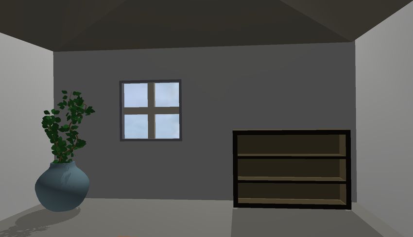
1

      Analysis of Locally Coupled 3D Manipulation
       Mappings Based on Mobile Device Motion
                                Paul Issartel∗ , Florimond Guéniat† , Tobias Isenberg‡ , and Mehdi Ammi§
                                             ∗ LIMSI-CNRS,Univ. Paris-Sud, paul.issartel@limsi.fr
                                   † Dept. of Mathematics, Florida State University, contact@gueniat.fr
                                                 ‡ INRIA Saclay, tobias.isenberg@inria.fr
                                          § LIMSI-CNRS, Univ. Paris-Sud, mehdi.ammi@limsi.fr

                                                                         F

    Abstract—We examine a class of techniques for 3D object
manipulation on mobile devices, in which the device’s physical
motion is applied to 3D objects displayed on the device itself. This
“local coupling” between input and display creates specific challenges
compared to manipulation techniques designed for monitor-based or
immersive virtual environments. Our work focuses specifically on
the mapping between device motion and object motion. We review
existing manipulation techniques and introduce a formal description of
the main mappings under a common notation. Based on this notation,
we analyze these mappings and their properties in order to answer
crucial usability questions. We first investigate how the 3D objects
should move on the screen, since the screen also moves with the
mobile device during manipulation. We then investigate the effects of
a limited range of manipulation and present a number of solutions to
overcome this constraint. This work provides a theoretical framework
to better understand the properties of locally-coupled 3D manipulation
mappings based on mobile device motion.
                                                                             Figure 1: Using the motion of a mobile device to translate
                                                                             and rotate a 3D object displayed on the device itself (locally
1    I NTRODUCTION                                                           coupled manipulation). This is illustrated here on different
                                                                             types of mobile devices. In this paper, we specifically focus
Mobile devices differ from traditional computers in that they                on the mapping between device motion and object motion.
combine input, display, and processing capabilities into a single
handheld object. Recent technological advances have made it
possible to run 3D applications directly on mobile devices. One of               In this paper, we investigate a different class of techniques
the fundamental tasks (Bowman et al., 2004) in such applications             which retain the advantages of tangible interaction but do not re-
is object manipulation, i. e. the translation and rotation of objects        quire any external objects. They consist in using the mobile device
in 3D space. A major challenge for 3D manipulation tool design is            itself as a tangible input device, by measuring its own motion
thus to create efficient 3D manipulation techniques, tailored to the         relative to the environment. In other words, these techniques use
unique characteristics of this portable and integrated environment.          the physical motion of the mobile device in the real world to control
                                                                             a 3D object on the device’s screen1 (Figure 1). Compared to the
    Currently, the most common way to interact with mobile
                                                                             previously mentioned interaction modes, this approach has clear
devices is by means of an integrated touch screen. Each contact
                                                                             advantages. Unlike touch input, it provides sufficient degrees of
on a touch screen provides two degrees of freedom (DOF). While
                                                                             freedom for 3D interaction. Unlike the tangible interfaces described
this type of input is well suited to 2D interaction, 3D manipulation
                                                                             above, it does not require any separate objects.
requires three degrees of freedom for translations and three for
                                                                                 However, this configuration also presents important challenges.
rotations. The constraint of 2-DOF input often leads to complex and
                                                                             The screen on which the manipulated object is displayed is coupled
unnatural 3D manipulation techniques. An alternative type of input
                                                                             with the input device—a “locally coupled” configuration (Rahman
exists in the form of tangible interaction: manipulating physical
                                                                             et al., 2009). Therefore, the screen moves and rotates along with
objects around the mobile device (Issartel et al., 2014). The motion
                                                                             the input device, a fundamental difference from the typical case of a
of these physical objects is then mapped to the 3D objects displayed
                                                                             fixed monitor with a separate input peripheral. This coupling raises
on the device’s screen. Tangible input integrates all six degrees of
                                                                             crucial usability questions. The first question is how to match visual
freedom required for 3D interaction into a simple and natural way
                                                                             feedback to device motion. Objects displayed on the screen appear
that takes advantage of real-world manipulation skills (Ishii, 2008).
One important drawback, though, is that the user must carry and                1. Note that this refers to object manipulation in screen space, rather than
handle several objects in addition to the mobile device.                     manipulation of objects located in an external reference frame.
2
to move from the user’s point of view, since the screen is moving tangible objects with built-in sensors (Katzakis and Hori, 2009;
during manipulation. This raises the issue of how the manipulated Ha and Woo, 2013; Benzina et al., 2012; Song et al., 2011; Ha
object should move on the screen itself, so that its apparent motion and Woo, 2011; Liang, 2013; Du et al., 2011). These interfaces
remains consistent with the device’s motion. Another question is allow users to manipulate virtual 3D objects through the motion
whether users see the device as a “handle” that controls the object, of a mobile device. Although device motion provides interactive
or a “window” that controls the viewpoint. A third issue is the control, the manipulated objects are still displayed on an external
limited range of manipulation. As with any handheld input device, screen. Thus, the manipulation does not actually occur on the
this range is limited by the space reachable by the user. But the mobile device itself.
screen is attached to the device itself. Since the screen provides Alternatively, tangible objects can be used in combination with
visual feedback, it must remain legible during manipulation, which a mobile device (Issartel et al., 2014; Liang, 2013): tangible objects
further reduces the usable range of motion. serve as input, while the mobile device processes and renders
In order to address the previous questions, it is essential to the manipulated 3D objects on its integrated screen. With this
understand well the mapping between device motion and object approach, the manipulation takes place on the mobile device as the
motion. In this analysis, we thus specifically focus on the mappings entire interface is portable and self-contained. However, the user
themselves. As we will see, several researchers have proposed also has to handle several objects during the manipulation which
manipulation techniques that were based on mobile device motion. can be ergonomically challenging. Moreover, external tangible
Many of them, however, have emphasized the application rather objects need to be inconveniently carried with the mobile device to
than the mapping. We thus aim to provide an explicit discussion wherever the interface is used.
and detailed description of the possible mappings, facilitating a The next logical step is to use a mobile device as tangible input
comprehensive understanding of their properties. to manipulate objects displayed on the device. We survey these
In this work, we contribute a theoretical framework for locally- types of approaches and discuss them within our framework.
coupled 3D manipulation mappings based on mobile device motion.
We begin with a review of existing manipulation techniques,
2.2 On-device interaction based on device motion
followed by a discussion of their common aspects. We then
introduce a formalization of the main mappings and unify them A number of existing mobile interaction techniques exploit the
under a common notation. Using this formalism, we proceed motion of a mobile device to translate and rotate objects on its own
with an analysis of these mappings in order to demonstrate their screen. Many such techniques are tailored for 1D or 2D interaction,
properties. Our analysis addresses two main questions: how the but some of them are actually designed for 3D manipulation.
object should move on the screen to match device motion, and
how to address the constraints of a limited motion space. For each 2.2.1 Tilt-based interaction
property of the mappings, we first examine existing arguments In one of the first works on the subject, Rekimoto (1996) proposed
from previous work. However, where previous evidence is lacking to use device inclination (“tilt-based interaction”) to navigate menus
or inconclusive, we contribute new theoretical and experimental on a palmtop computer. According to the given description, the
results to answer the above questions. Based on this analysis, current position within the menu directly depends on the device
we finally discuss possible adaptations and improvements for angle. Weberg et al. (2001) also described an interface that uses
each mapping. By providing a comprehensive, formalized, and the device’s tilt to navigate menus and select menu items on a
substantiated overview of these mappings, our framework assists PDA device. In this case, however, the device inclination controls
designers in making more informed choices when implementing the rate of motion within the menu. Oakley and O’Modhrain (2005)
such techniques. evaluated both approaches for menu selection. We can thus identify
two ways of mapping mobile device motion to a manipulated
2 E XISTING MANIPULATION TECHNIQUES object: one that directly controls the position of the object (position
control), and another that controls its rate of motion (rate control).
As a first step to establish our theoretical framework, we review ex-
Many other works have investigated tilt-based interaction.
isting 3D manipulation techniques based on mobile device motion.
Scrolling in lists, documents, and images by tilting a mobile device
seems to be a frequently studied task. Early works (Small and
2.1 3D manipulation through physical objects Ishii, 1997; Harrison et al., 1998; Bartlett, 2000) appear to use
The idea of using a handheld physical object—in this case, a rate control, but the exact mapping is only informally described.
mobile device—to manipulate virtual 3D objects can be related to Unfortunately, the lack of formalization makes these mappings
graspable user interfaces (Fitzmaurice, 1996) and, more generally, ambiguous and difficult to compare to each other. Subsequent
to tangible interaction (Ishii, 2008). One of the earliest examples works on tilt-to-scroll (Hinckley et al., 2000; Eslambolchilar and
was the PassProps prototype by Hinckley et al. (1994) in which Murray-Smith, 2008; Cho et al., 2007) then introduced more
tangible objects are tracked in real space and their position and formally described rate control mappings. Rahman et al. (2009)
orientation are mapped to 3D objects shown on an external display. present a thorough study of tilt-based position control mappings
Similar examples are the Cubic Mouse (Fröhlich et al., 2000) and for 1-DOF discrete input. Tilt-based interaction has also been used
the CID device (van Rhijn and Mulder, 2006). The use of tangible for 2D panning and zooming. The RotoView technique (Feinstein,
objects for manipulation is a rather natural mode of interaction 2002), for example, facilitates map navigation with a rate control
since it exploits the user’s real-world manipulation skills (Ishii, mapping. Joshi et al. (2012) present a hybrid position-rate control
2008). The projects mentioned above, however, require custom- mapping to visualize 360° panoramas. Finally, tilt-based interaction
made objects and specific sensors for input and tracking. has been studied for pointing. Tsandilas et al. (2013) compared
With the increasing availability of mobile devices, many rate control, position control and hybrid control for 1D pointing,
projects have proposed to use handhelds as readily-available with formal descriptions of each mapping. Teather and MacKenzie3
(2014) compared position control and rate control mappings for a manipulation, the object remains fixed relative to the mobile device.
2D pointing task. This task is closer to a 3D manipulation than A drawback of this approach is that it makes it difficult to rotate
previous examples, since it involves accurate manipulation of an the manipulated object without translating it. Since the virtual
object (pointer) on the screen with multiple degrees of freedom. scene is fixed in an external reference frame and the manipulated
object is fixed in the device reference frame, the mobile device
2.2.2 Spatially-aware displays must be moved across an arc. The HOMER-S technique (Mossel
The tilt-based techniques mentioned so far only use device orien- et al., 2013) eliminates this issue by separately applying device
tation as input. Interfaces where the position of a mobile device rotations to the manipulated object. As a consequence, however,
serves as an input modality tend to be categorized as spatially- the object is no longer fixed relative to the mobile device and
aware displays. For example, Small and Ishii (1997) presented a can thus leave the field of view during large rotations. These
system to visualize long paintings, using a wheel-mounted monitor approaches cannot avoid both of these problems as they are caused
which scrolls its contents when rolled on the floor. Its mapping is by the intrinsic separation between the object’s reference frame
not described in detail but appears to be position-controlled. Yee and the device’s reference frame in normal perspective rendering.
(2003) presented the “peephole display” in which movements of A different approach is the concept proposed by Spindler et al.
a PDA—tracked with tethers—allow the user to pan and navigate (2012) which uses a head-coupled perspective to let the device
workspaces larger than the device’s screen. Again, the mapping intersect the manipulated object, thus greatly reducing its separation
is position-controlled but not formally described. Spindler et al. from the object. Assuming head tracking is available—which can
(2014) demonstrated a similar approach with an infrared-tracked be challenging to accomplish in a truly mobile interface—this
mobile device. Wang et al. (2006) used a mobile device’s internal approach can solve the rotation issue. Yet, all the “grasping”
camera to track its own translations and rotations, mapping them to techniques share another drawback: the object must remain fixed
various 2D interaction tasks. In one of the only works to mention relative to the device, thus the translation mapping is restricted to
both position and rate control mappings in a spatially-aware display, isomorphic position control even though different mappings might
Hansen et al. (2006) also used the integrated camera to track the be desirable in some situations (Section 6).
device position and orientation, for several possible applications. The alternative is to perform 3D manipulation entirely in the
Overall, there seems to be fewer works that exploit device device reference frame, i. e. in screen space, avoiding the constraints
position than device orientation. This fact may be due to the caused by an external reference frame. Kratz and Rohs (2010)
complexity of tracking a position compared to an orientation. compared a tilt-based rotation mapping with a two-sided touch
The device orientation can be easily tracked with integrated and metaphor on a smartphone. Their tilt-based mapping uses rate
inexpensive sensors, such as gyroscopes and magnetometers. Such control but only supports rotation on two axes. Neale et al. (2013)
sensors have long been found in many mobile devices. In contrast, presented an interface to visualize museum artifacts on a tactile
tracking the device position is more difficult. Some of the above tablet. They compared touchscreen input to both tilt-based position
projects use wheels, wires, or external infrared (IR) sensors which control and rate control mappings. This interface, however, only
are unwieldy and impractical in a mobile setting. Other projects supports object rotation and the mappings are not described in
choose to use an integrated camera. Now that cameras are becoming detail. Daiber et al. (2012) presented an interface to translate and
ubiquitous and embedded processing power becomes sufficient for rotate 3D objects on a smartphone. The tilt-based rotation mapping
real-time image analysis, inside-out optical tracking seems to be appears to be position-controlled. Their translations, however, are
the most promising solution for small scale position tracking on not based on device motion but on touch gestures. The PDDM
a mobile device. The recently launched Tango project2 , a tactile device by Noma et al. (1996) is a rare example of using both device
tablet featuring inside-out motion tracking, may open the way for translations and rotations for screen-space 3D manipulation. The
more applications of position tracking. device is a palmtop monitor mounted on a mechanical arm. The
authors presented four different mappings for screen-space object
2.2.3 3D manipulation based on device motion manipulation, all based on position control. The mappings are
Although the mapping of device motion to 1D or 2D tasks can serve explained and illustrated, but not formally described. Furthermore,
as a basis for 3D manipulation mappings, there is no substitute the study of the mappings themselves was still limited in scope.
for studies focusing on actual 3D tasks. Only such studies can Important questions such as the frame of reference of manipulation
highlight the constraints and challenges specific to 3D interaction. were only mentioned as future work.
Fitzmaurice et al. (1993) described the Chameleon system in As we can see, a few existing works use the motion of a mobile
which the position of a handheld monitor controls the viewpoint device for actual screen-space 3D manipulation. But each of them
on a displayed 3D scene. Subsequent works (Tsang et al., 2002) only addresses a small subset of the possible mappings. Some only
later improved this concept by tracking the device orientation in consider rotations and ignore translations, others only use position
addition to its position, facilitating a full control of the viewpoint. control, and yet others only consider rate control. The authors
These projects, however, primarily simulated a window on a virtual generally do not provide a formal description of the proposed
scene—restricting the possible mappings to an isomorphic position mappings, making it difficult to generalize the results. In particular,
control and excluding other mappings that might be useful for the lack of a formal notation makes it impossible to assess key
3D object manipulation. usability properties such as the matching between visual feedback
Other projects use the motion of a mobile device for actual and device motion and how well the proposed mappings make use
3D manipulation. Some of them demonstrate 3D object manipula- of the limited motion space. In the rest of the paper we, therefore,
tion in augmented reality (AR). Henrysson et al. (2005) and Marzo conduct an in-depth analysis of the mappings themselves and their
et al. (2014) described a “grasping” metaphor in which, during the properties. We start by presenting a formalization of the main
mappings and then use this notation to determine how well they
2. http://www.google.com/atap/project-tango/ address the above-mentioned usability questions.4
3 A BOUT THE TERM “ MOBILE DEVICE ”
Early approaches that used device motion as an input modality qci-1
associated the mobile device concept with technologies such as
v v'
portable TVs, PDAs, and palmtop computers. Today, the term screen
“mobile device” generally refers to smartphones, tablets, phablets, space
or a size variation thereof. These devices all share a similar form
tracker
factor: they are mostly flat, rectangular, and have a single screen
on one side. qci v space
There is no reason, however, why a 3D manipulation mapping
device
could not work with other device shapes (e. g., Figure 1). There
translation
have been proposals for adding a screen on the other side of current
mobile devices (e. g., Kratz and Rohs, 2010), for creating highly Figure 2: Directly applying the measured device translation v
deformable mobile devices (e. g., Ramakers et al., 2014), and to the manipulated object would move it in unexpected direc-
for creating tiltable devices (e. g., Alexander et al., 2012). The tions, depending on the device orientation qci in tracker space.
recent interest for “smart watches” is driving the industry and To get a more predictable behavior, the vector v should be
academia toward the development of wristband-shaped displays rotated by the inverse rotation qc−1
i , producing the correct
(e. g., Lyons et al., 2012). There are prototypes of small, portable translation v0 . The same process is applied to rotations.
cubic displays (Lopez-Gulliver et al., 2009; Stavness et al., 2010)
with a screen on each face, capable of displaying a 3D scene as
if it were inside the cube. Spherical screens (Benko et al., 2008) works, we consider both translations and rotations in our formal
and volumetric globes (Grossman and Balakrishnan, 2006) are model. We also provide a pseudocode description in the appendix.
also being investigated. These remain too large to be considered
“mobile”, but could be down-sized as technology advances. Future 4.1 Basic notation
mobile devices might thus have a radically different shape than The values pct and qct represent the position and orientation,
current ones. respectively, of the mobile device at time t. They are the control
In this article we thus define a mobile device in a rather values, obtained from tracking and expressed in an arbitrary
generic way: any interactive physical (tangible) object that can tracking-specific coordinate system. The position pct is a 3D vector,
be easily carried by one person’s own hands and is capable of while the orientation qct is a quaternion that represents the rotation
displaying virtual objects on its surface or inside its volume. All of the device relative to some base orientation.
our conclusions remain applicable to any device which corresponds The values pdt and qdt represent the position and orientation
to this definition, unless otherwise specified. of the manipulated object at time t. They are the display values,
There is still an additional requirement for a mobile device to expressed in the screen coordinate system. The position pdt is a
be compatible with the 3D manipulation mappings discussed here. 3D vector, while the orientation qdt is a quaternion that represents
The manipulated virtual object must appear to have a single defined the rotation of the object relative to some base orientation on the
position and orientation within the device reference frame. The screen. The display values pdt and qdt are computed from the
reason for this additional constraint is that it would be impossible control values by applying the mapping function.
to know the exact location of the object, and object manipulation Time t = 0 designates the beginning of manipulation, i. e. the
would no longer make sense, if multiple copies of a single virtual time when the user starts manipulating the object.3 The values pc0
object were to appear at conflicting locations. and qc0 thus represent the initial position and orientation of the
This constraint, however, normally does not pose a problem for mobile device. Similarly, pd0 and qd0 represent the initial position
devices that have a single flat screen since there is only one view of and orientation of the manipulated object. Each subsequent time t
the virtual scene. For devices with multiple non-coplanar screens or indicates the time when a new sample is obtained from the tracking
devices covered with a curved screen, special care must be taken to system. Time increments are unitary in our notation.
ensure that a virtual object does not appear at multiple conflicting
locations. This can be accomplished with perspective correction,
i. e. by ensuring that each screen (or each point of the surface) shows 4.2 From tracker coordinates to screen coordinates
the virtual scene from a different perspective such that a virtual Control values (positions pct and orientations qct of the mobile
object appears at a fixed location within the device volume. This device) are measured by the tracking system in a tracking-specific
solution requires either autostereoscopic displays (Lopez-Gulliver reference frame. Consequently, the motion of the mobile device
et al., 2009), true volumetric displays (Grossman and Balakrishnan, is also expressed in this reference frame. But the manipulated
2006), or a way to continuously track the position of the user’s object belongs to the screen reference frame. Therefore, the
eyes in order to update the perspective (Stavness et al., 2010). mapping function must convert device motion into the screen
reference frame.
In the locally coupled configuration we study here, the screen
4 F ORMALIZATION OF THE MAIN MAPPINGS is attached to the input device itself. Thus, a rotation of the
device during manipulation also rotates the screen in relation to
A mapping, also called transfer function, describes how device
the tracking system, causing the screen and tracking reference
motion is mapped to object motion on the screen and we now
frames to become misaligned (Figure 2). If the measured device
present the main ways to perform such a mapping. We express
them in a unified formal notation, allowing us to compare them and 3. Users should be able to explicitly engage or disengage manipulation mode
assess their properties in the next sections. Unlike many previous with, e. g., a dedicated button to move the device without affecting the object.5
motion was directly applied to an object on the screen, the object mappings, whereas a relative sensor is not suitable for absolute
would move in unexpected directions. Converting device motion mappings due to drift. However, relative inside-out sensors are
into the screen reference frame requires to compensate for this generally fully contained in the mobile device itself and do not
misalignment. depend on the external environment, which is a strong benefit for
Consider a translation v and a rotation r of the mobile device, portability. Although some absolute sensors can be physically
measured in the tracking reference frame between times i and j. At embedded in the device (e. g., cameras and magnetometers), they
the beginning of movement, the device orientation in the tracking are easily disrupted by some environmental conditions (lack of
reference frame is qci . Since the screen is attached to the mobile visual markers, insufficient or excessive ambient light, presence of
device, the screen orientation is also qci (for the sake of simplicity, magnetic materials, etc.). Thus, the use of relative sensors rather
we assume a null offset between the device and the screen). To than absolute ones might be dictated by technical constraints.
map v and r to the screen reference frame, this orientation must be Aside from these practical aspects, the distinction between
canceled, hence re-aligning the reference frames (Figure 2). We absolute and relative tracking also has an impact on usability
achieve this re-alignment by applying the inverse rotation qc−1 i to since—as we demonstrate next—absolute and relative position
v and r. We thus apply this inverse rotation to the direction (the control mappings do not have the same properties.
vector part) of the quaternion r using the conjugation operation
qc−1 −1 −1 −1
i r (qci ) , shortened to qci r qci . For this purpose we
4.3.1 Absolute mapping
consider the translation vector v as a quaternion whose real part An absolute mapping (Poupyrev et al., 2000; Bowman et al.,
is zero, and apply the same operation. In summary, the new 2004) directly applies the device position and orientation (pct and
translation v0 and rotation r0 (corresponding to the translation v and qct ) to the manipulated object position and orientation (pdt and
the rotation r measured by the tracking system) are hence obtained qdt ). To make incremental manipulation possible, the mapping
as follows: must take into account the initial position and orientation of the
v0 = qc−1 object (pd0 and qd0 ). To ensure that the object does not move
i v qci
(1) unexpectedly at the beginning of manipulation, it is also necessary
r0 = qc−1
i r qci to subtract the initial position and orientation of the mobile device
This transformation expresses device translations and rotations (pc0 and qc0 ). This corresponds to a translation pct − pc0 and
in a stable reference frame. We can now apply these transformations a rotation qct qc−1
0 which are to be applied to the object’s initial
to a 3D object displayed on the screen. As demonstrated in previous position pd0 and orientation qd0 . As we explained in Section 4.2,
work, however, there are different ways to apply device motion to the device translations and rotations must be converted into screen
a manipulated object (Figure 3) as we will see next. space. Since they are measured from the initial device location
at t = 0, a rotation of qc−10 is applied. The absolute mapping is
thus given by:
4.3 Position control mappings
∆pct = qc−1
0 (pct − pc0 ) qc0
In a “position control” (or zero-order) mapping, the motion of
an input device directly controls the position and orientation of ∆qct = qc−1 −1
0 (qct qc0 ) qc0
(2)
the manipulated object (Zhai, 1995). In our case this means pdt = ∆pct + pd0
that translations of the mobile device control the position of qdt = ∆qct qd0
the displayed object, while rotations of the device control the
orientation of the object. 4.3.2 Relative mapping
Two main ways of mapping exist to control an object’s position Rather than directly applying the device position and orientation to
and orientation. The first one—an “absolute” mapping—directly the object, we can also apply incremental translation and rotation
assigns the position and orientation of the mobile device to the offsets. A relative mapping (Poupyrev et al., 2000; Bowman
object, as measured in some fixed reference frame. The other et al., 2004) applies incremental device translations and rotations,
way—a “relative” mapping—applies incremental translations and measured between times t−1 and t (pct − pct−1 and qct qct−1 −1
,
rotations of the device (i. e., its change in position and orientation respectively), to the current object position and orientation (pdt−1
between each times t and t−1) to the object. Our notion of and qdt−1 , resp.). Again, device translations and rotations must
absolute and relative mappings reuses the terminology proposed be converted into screen space. Since they are measured from
by Poupyrev et al. (2000) for rotations, which we extend to also −1
time t−1, a rotation of qct−1 is applied. The relative mapping is
include translations. thus given by:
Absolute and relative sensors The distinction between
−1
absolute and relative mappings has a practical significance. Some ∆pct = qct−1 (pct − pct−1 ) qct−1
tracking sensors measure an “absolute” position or orientation, −1 −1
∆qct = qct−1 (qct qct−1 ) qct−1
i. e. expressed in a static reference frame outside of the mobile (3)
pdt = ∆pct + pdt−1
device. For example, a mechanical arm can measure the location of
qdt = ∆qct qdt−1
the device relative to its base, and a magnetometer can measure the
orientation of the device in the Earth’s reference frame. An embed- In order to unify all the main mappings under a common
ded camera can track a fixed marker in the environment (Hansen formalism, our notation assumes the availability of absolute
et al., 2006) or sense IR light reflected from the surrounding tracking information. However, relative sensors embedded into the
environment (Tango project) to measure the device’s position and device (such as gyroscopes) provide incremental device translations
orientation. Other sensors only measure relative motion such as and rotations. Since those incremental translations and rotations are
the gyroscopes or accelerometers found on many current devices. already expressed in the device’s reference frame, they do not have
An absolute sensor can be used with both absolute and relative to be converted into screen space. Therefore, the values returned6
(initial state) absolute position control relative position control rate control
Figure 3: Three main ways to map mobile device motion to a 3D object’s motion, shown for a tablet. Absolute position control:
the device displacement from its initial location is applied to the object. Relative position control: the incremental device
displacement is applied to the object. Rate control: the device displacement from its initial location controls the object’s velocity.
by such sensors can be directly used in place of the ∆pct and ∆qct to perform worse than position control and rate control (Massimino
terms in Eq. 3. et al., 1989; Zhai, 1995). We thus do not consider them here.
As a consequence, only the relative position-control mapping
should be used with relative sensors, since it does not require the 4.6 Control-display gain
absolute pct and qct values to be known (unless the sensor values
are integrated, ultimately leading to drift). The mappings as they are formulated above do not change the
scale of device movements which are applied to the object. Such
4.4 Rate control mapping mappings are called isomorphic (Poupyrev et al., 2000; Zhai,
In a “rate control” (or first-order) mapping, the motion of the input 1995). However, we can easily extend them to amplify or reduce
device controls the velocity (linear or angular) of the object (Zhai, translations and rotations. The resulting mappings then become
1995). The mobile device can be translated and rotated in 3D space non-isomorphic.
from its initial position pc0 and orientation qc0 . In a rate control We thus introduce a gain function to our framework that
mapping, the linear velocity of the manipulated object increases computes a scalar gain factor kt at each time t:
when the mobile device moves away from its initial position, and kt = gain(t)
decreases when returning to this point. The linear velocity thus
depends on the translation vector pct − pc0 . Similarly, the angular This gain factor allows us to rescale the device translations and
velocity of the manipulated object depends on the rotation of rotations before applying them to the object, so that the object on
the device from its initial orientation, i.e., qct qc−1
0 . Since those the screen can move faster or slower than the device itself. For
displacements are relative to the initial device location (at t = 0), a translation, the gain factor changes its length without altering
a rotation of qc−10 is applied to convert them to screen space. its direction. This is accomplished by scaling the translation
Applying a linear and angular velocity to an object means adding vector ∆pct by the gain factor kt , yielding a new translation vector
these to its current position and orientation (pdt−1 and qdt−1 ) at ∆pct0 :
each time t. The rate control mapping is thus given by:
∆pct0 = kt ∆pct
∆pct = qc−1
0 (pct − pc0 ) qc0
∆qct = qc−1 −1
0 (qct qc0 ) qc0
In the case of a rotation of angle θ around a given axis, the
(4) gain factor changes the angle without altering the axis. If the
pdt = ∆pct + pdt−1
rotation ∆qct is expressed as a quaternion, we can use a slerp
qdt = ∆qct qdt−1
interpolation (Shoemake, 1985) from the identity quaternion 1 to
4.5 Higher-order control construct a new rotation ∆qct0 around the same axis but with an
angle scaled by kt . We note this operation as ∆qctkt . If ∆qct is a
Position control is a zero-order mapping: it directly maps device
non-null rotation, the new rotation ∆qct0 = ∆qctkt is given by:
positions and orientations to the object. Rate control is a first-
order mapping: it maps the device location to the object velocity, ∆qct0 = slerp(1, ∆qct , kt )
i. e. the derivative of position and orientation. While higher-order = ∆qctkt
mappings such as acceleration control4 are possible, they are known
By substituting ∆pct and ∆qct with kt ∆pct and ∆qctkt in the
4. The metaphor for a second-order mapping would be an impulse being
applied to an object that causes it to continue moving until a reverse impulse is mappings presented above, it becomes possible to dynamically
applied—similar to what happens on space vehicles (Massimino et al., 1989). control the gain applied to translations and rotations.7
The gain factor in our model is a function of the current time. rotations relative to the screen. Thus, a mapping is directionally
Unlike some previous works (e. g., Teather and MacKenzie (2014); compliant at time t if it can be expressed as:
Poupyrev et al. (2000); LaViola and Katzourin (2007)) which only
used static scaling coefficients, we emphasize that the gain may ∃ (α, β ) ∈ R2 :
dynamically change during manipulation. Such a variable gain −1
pdt − pdt−1 = α qct−1 (pct − pct−1 ) qct−1
factor is especially useful to increase the range and accuracy of β (5)
−1 −1 −1
manipulation as we show in Section 6.2. We thus indicate below qdt qdt−1 = qct−1 (qct qct−1 ) qct−1
whether the properties of each mapping remain true even with a
variable gain factor. Relative position control. The relative position control
mapping is always directionally compliant, for both transla-
tions and rotations. From the mapping formulation (Eq. 3),
and by taking into account the gain factor (Section 4.6), we
5 S PATIAL FEEDBACK COMPLIANCE get pdt − pdt−1 = kt ∆pct = kt qct−1 −1
(pct − pct−1 ) qct−1 and
−1 −1 −1
kt
When users are moving a mobile device to control a 3D object on qdt qdt−1 = ∆qctkt = qct−1 (qct qct−1 ) qct−1 —equivalent to the
the screen, they receive multiple forms of feedback. The first is expression in Eq. 5. Relative position control thus always guaran-
kinesthetic/proprioceptive feedback from translating and rotating tees directional compliance for both translations and rotations.
the device itself. The second is visual feedback from the resulting Absolute position control. The absolute position control
object motion on the screen. To maintain user performance and mapping does not guarantee directional compliance in the general
comfort it is thus essential that the visual feedback matches the case. However, directional compliance can still be obtained under
kinesthetic/proprioceptive feedback (Smith and Smith, 1987)—a specific conditions. By taking into account a variable gain factor,
principle known as feedback compliance (Bowman et al., 2004). we can express object translations between two times t−1 and t as:
Here, we focus specifically on spatial feedback compliance, which pdt − pdt−1
refers to the motion of the virtual object and is thus especially
= (kt ∆pct + pd0 ) − (kt−1 ∆pct−1 + pd0 )
relevant when designing mappings.
In this section we discuss the spatial compliance properties = kt ∆pct − kt−1 ∆pct−1
(6)
= kt qc−1 −1
of each mapping, both for translations and for rotations. We 0 (pct − pc0 ) qc0 − kt−1 qc0 (pct−1 − pc0 ) qc0
begin with the two properties mentioned by Bowman et al. (2004), = qc−1 −1
0 kt (pct − pc0 ) qc0 − qc0 kt−1 (pct−1 − pc0 ) qc0
directional and nulling compliance, along with the property of
= qc−1
0 kt (pct − pc0 ) − kt−1 (pct−1 − pc0 ) qc0
transitivity (Bade et al., 2005). Finally, we address the question of
the user’s reference frame (allocentric or egocentric) and whether Thus, in the general case, object translations do not correspond to
object motion matches the reference frame expected by the user. expression Eq. 5 and are not directionally compliant. For constant
gain factors kt (kt = α ∀t>0), however, Eq. 6 can be reduced to:
= qc−1
0 α (pct − pc0 ) − α (pct−1 − pc0 ) qc0
5.1 Directional compliance
= qc−1
0 α (pct − pc0 ) − (pct−1 − pc0 ) qc0
Directional compliance (Bowman et al., 2004; Poupyrev et al., = qc−1
0 α (pct − pct−1 ) qc0
2000), also called “kinesthetic correspondence” (Britton et al.,
= α qc−1
1978) or “stimulus-response compatibility” (Fitts and Seeger, 1953), 0 (pct − pct−1 ) qc0 (7)
means that the manipulated object moves along the same direction Moreover, if at t−1 the mobile device orientation qct−1 is equal to
as the controlling device. In the configuration studied here, the its initial orientation qc0 then object translations can be written as:
object moves on the screen and is controlled by the mobile device’s
−1
motion. The screen itself, however, is attached to the device = α qct−1 (pct − pct−1 ) qct−1
and is also moving during manipulation. It is thus important to
This corresponds to Eq. 5. Translations in the absolute mapping
consider device motion relative to the screen (i. e., in screen space).
are thus only directionally compliant if the gain factor remained
Directional compliance, therefore, means that the object is moving
constant between t=0 and t−1 and if the mobile device orientation
on the screen along the same direction as the device is moving
is the same as its initial orientation. Concerning rotations,
relative to the screen (Figure 4).
incremental object motion can be written as:
Note that the conversion to screen space described in Section 4.2
−1
ensures that device motion is consistently aligned with screen qdt qdt−1
space at t = 0, but does not guarantee directional compliance at any k
= (∆qctkt qd0 ) (∆qct−1
t−1
qd0 )−1
subsequent time during manipulation. −k
Object motion corresponds to the change of position and = (∆qctkt qd0 ) (qd0−1 ∆qct−1t−1 ) (8)
−k
orientation on the screen between times t−1 and t: pdt − pdt−1 and = ∆qctkt ∆qct−1t−1
−1
qdt qdt−1 , resp. Mobile device motion corresponds to the change kt −kt−1
= qc−1 −1
0 (qct qc0 ) qc0 qc−1 −1
0 (qct−1 qc0 ) qc0
of position and orientation in tracking space between times t−1
−1
and t: pct − pct−1 and qct qct−1 , resp. As before, a rotation In the general case, rotations do not correspond to the form stated
−1
of qct−1 must be applied to this device motion to convert it to in Eq. 5 and are not directionally compliant. However, if qct qc−1 0
screen space. Formally stated, directional compliance means that (device rotation from its initial orientation at time t) and qct−1 qc−1
0
object translations are collinear with device translations relative to (same at time t−1) have the same rotation axis then their difference
−1
the screen, and that object rotations have the same axis as device qct qct−1 also has the same rotation axis. There exist, therefore,8
Device motion Directional compliance a scalar a such as pct − pc0 = a (pct − pct−1 ) and Eq. 10 can be
yes no rewritten as:
= kt qc−1
0 (a (pct − pct−1 )) qc0
= (a kt ) qc−1
0 (pct − pct−1 ) qc0
= α qc−1
0 (pct − pct−1 ) qc0
We find the same expression as Eq. 7, which leads to Eq. 5 if we
make the second assumption that device orientation at t−1 is equal
to its initial orientation qc0 (see the previous proof on the absolute
mapping for more details). Thus, translations in the rate control
mapping are only directionally compliant along the first translation
Figure 4: Directional compliance versus non-compliance, axis and if the device orientation is equal to its initial orientation.
shown here on a tablet-shaped device. Rotations exhibit a similar behavior:
−1 −1
qdt qdt−1 = (∆qctkt qdt−1 ) qdt−1
two gain factors a1 and a2 such as qct qc−1
= 0
−1 a1
(qct qct−1 ) and = ∆qctkt (11)
qct−1 qc−1
0 = (qct qc −1 a2
) and Eq. 8 can be rewritten as: kt
t−1
= qc−1
0 (qct qc−1
0 ) qc0
kt −kt−1
= qc−1 −1 a1
0 (qct qct−1 ) qc0 qc−1 −1 a2
0 (qct qct−1 ) qc0
In the general case, this expression is not equivalent to Eq. 5.
a1 +kt a2 −kt−1 However, if we assume that all device rotations happened on the
= qc−1 −1
qc−1 −1
0 (qct qct−1 ) qc0 0 (qct qct−1 ) qc0 same axis since the beginning of manipulation, then there exists a
a1 +kt +a2 −kt−1
= qc−1 −1
0 (qct qct−1 ) qc0 scalar b such as qct qc−1 −1 b
0 = (qct qct−1 ) and Eq. 11 can be rewritten
as follows:
kt
With a1 + kt + a2 − kt−1 ≡ β , we can reduce the above to:
= qc−1 0 (qct qc −1 b
t−1 ) qc 0
−1 −1
kt +b
= qc−1 −1
β
0 (qct qct−1 ) qc0
(9) = qc0 (qct qct−1 ) qc0
β
= qc−1 −1
0 (qct qct−1 ) qc0
Since qct−1 qc−1 0
−1 a2
= (qct qct−1 ) , we have qc−1 0 =
−1 −1 a2 We find the same expression as Eq. 9, which directly leads to Eq. 5
qct−1 (qct qct−1 ) . The above expression can thus be rewritten as:
since we assumed that all device rotations were performed about
−1 −1 a2 −1 −1
β
−1 a2 –1
the same axis (see the previous proof for more details). As with the
= qct–1 (qct qct–1 ) (qct qct–1 ) qct–1 (qct qct–1 ) absolute mapping, rotations in the rate control mapping are thus
−1
= qct–1 −1 a2
(qct qct–1 ) (qct qct–1−1 −1 −a2
) (qct qct–1 ) qct–1
β only directionally compliant around the first rotation axis.
−1 −1 a2 +1−a2
β
= qct–1 (qct qct–1 ) qct–1
5.2 Transitivity and nulling compliance
−1 −1
β
= qct–1 (qct qct–1 ) qct–1 Transitivity (Bade et al., 2005) refers to a property of the real world:
moving an object from point A to point B then C, or directly from A
to C, results in the same final location for the object. According
This corresponds to Eq. 5. Hence, object rotations in the absolute to this principle, translating and rotating the mobile device from A
mapping are only directionally compliant around the first, initial to B then C, or directly from A to C, should bring the manipulated
rotation axis. In practice, this means that only the first rotation object to the same position and orientation (Figure 5). In particular,
step is directionally compliant: subsequent rotations are not if they this property allows users to easily return the object to its initial
happen on a different axis. Therefore, users who wish to rotate the location—which can be useful after a manipulation error—by
object around another axis would have to return the device to its simply returning the mobile device to its initial location. This
initial orientation in order to maintain directional compliance for specific case is known as nulling compliance (Poupyrev et al.,
further rotations. 2000). Transitivity is a generalization of nulling compliance to any
Rate control. The rate control mapping does not guarantee target location.
directional compliance in the general case, both for translations Absolute position control. The absolute position control
and for rotations. By taking into account a variable gain factor, we mapping is generally transitive, for both translations and rotations.
can express object translations between two times t−1 and t as: The only terms in the mapping formulation (Eq. 2) that are non-
constant during manipulation are pct and qct . The base formulation
pdt − pdt−1 = ( kt ∆pct + pdt−1 ) − pdt−1
of the absolute mapping only depends on the current position and
= kt ∆pct (10) orientation of the mobile device, regardless of the intermediate
qc−1
= kt 0 (pct − pc0 ) qc0 steps that led it there. An isomorphic absolute mapping is thus
always transitive. For a non-isomorphic mapping, however, we
Since this expression is not equivalent to Eq. 5, translations in a must also take the gain function into account. A non-isomorphic
rate control mapping are not directionally compliant in the general absolute mapping is only transitive if the gain function itself does
case. However, if we assume that all device translations were not depend on non-constant terms other than pct and qct . This
performed along the same axis since the beginning of manipulation, is obviously the case for any constant gain factor. But adding
then pct − pct−1 is collinear with pct − pc0 . There exist, therefore, non-constant parameters to the gain function other than pct and qct9
Device motion Result must also have been constant during manipulation (ki = kt ∀i0) then pdt is reduced to: This has a notable effect on rotations. On a mobile device, the
step
manipulated object is displayed on the screen, which is rotating
pdt = qc−1
0 kt (pct − pct−1 ) along with the device during manipulation. By applying the exact
(12)
+ ... + k1 (pc1 − pc0 ) qc0 + pd0 opposite of the screen rotations to the object, these rotations are
canceled from the user’s point of view. The manipulated object will
Eq. 12 applies arbitrary gain factors to each intermediate translation thus appear to have a fixed orientation relative to the real world.
step. For Eq. 12 to become equivalent to pdtdirect , the gain factor Interestingly, the effect is identical in the absolute and relative10
Device motion Result to be stationary if device orientation remains equal to qc0 . In the
allocentric egocentric relative mapping, a constant gain factor of −1 yields:
pdt = − ∆pct + pdt−1
−1
= − qct−1 (pct − pct−1 ) qct−1 + pdt−1
−1
= qct−1 (pct−1 − pct ) qct−1 + pdt−1
−1
= qct−1 (pct−1 − pct ) qct−1
+ ... + qc−1
0 (pc0 − pc1 ) qc0 + pd0
Even though the opposite of each device translation substep
pct − pct−1 is applied to the manipulated object, each substep
is first converted to screen space according to the intermediate
Figure 6: Difference between allocentric and egocentric device orientation. The total object translation thus depends on
manipulation. intermediate device orientations. The object position will only
appear to be fixed relative to the real world if device orientation
does not change during manipulation, and thus remains equal
mappings. For a constant gain factor kt = −1 ∀t>0, the absolute to qc0 .
mapping results in the following object orientations: Note that simultaneously performing translations and rotations
with a gain factor of −1 would therefore not result in an AR-like
qdt = ∆qct−1 qd0 mapping—i. e., the object having both a fixed position and a fixed
−1
= qc−1 −1
0 (qct qc0 ) qc0 qd0 orientation relative to the real world—at least under the above
= qc−1 (qc qc −1 −1
) qc
formulation of the position-control mappings.
0 t 0 0 qd0
−1 −1
= qc0 (qc0 qct ) qc0 qd0
5.4 Summary of spatial compliances
= (qct−1 qc0 ) qd0
Table 1 summarizes spatial compliance properties of each mapping,
both for translations and rotations. With kt = −1 we indicate that the
And the relative mapping results in:
property is only guaranteed when the gain factor kt (see Section 4.6)
remained constant and equal to −1 since the start of manipulation.
qdt = ∆qct−1 qdt−1
−1
= qct−1 −1
(qct qct−1 ) qct−1
−1
qdt−1 Table 1: Spatial compliances of each mapping.
−1
= (qct−1 qct )−1 qdt−1 directional compliance transitivity
−1
= (qct−1 qct )−1 (qct−2
−1
qct−1 )−1 ... (qc−1
0 qc1 )
−1
qd0 translation rotation translation rotation
= (qct−1 qct−1 ) (qct−1
−1
qct−2 ) ... (qc−1
1 qc0 ) qd0 absolute noa kt = −1b yes yes
= (qct−1 qc0 ) qd0 relative yes yes noc kt = −1
rate nod nob no no
Hence, rotations become strictly equivalent in absolute and relative
mappings for a constant gain factor kt = −1. This implies that they a. unless the gain factor is constant and the device orientation is equal to
its initial orientation
now share the same spatial compliances. Rotations in the absolute
b. unless the device only rotates about a single axis, in which case
mapping become directionally compliant, as in the equivalent rotations remain directionally compliant
relative mapping. Rotations in the relative mapping become
c. unless the gain factor is constant and there is no device rotation (either
transitive, as in the equivalent absolute mapping. A gain factor its rotation is ignored, or its orientation does not change)
of −1 is thus the only way to have both directional compliance and d. unless all translations occur along a single axis and the device
transitivity for rotations in position control mappings. orientation is equal to its initial orientation
The same equivalence, however, is not guaranteed for transla-
tions. As we showed before, spatial compliances of translations
not only depend on the device’s position but also on its orientation. 5.5 Choosing between spatial compliances
In the absolute mapping, a constant gain factor kt = −1 results in From the results shown in Table 1, we see that none of the three
the following object positions: mappings provide both directional compliance and transitivity in
all cases. Furthermore, a choice must be made between allocentric
pdt = −∆pct + pd0 and egocentric manipulation. In this section, we present arguments
= − qc−1
0 (pct − pc0 ) qc0 + pd0 and evidence to help designers choose between these alternatives.
= qc−1
0 (pc0 − pct ) qc0 + pd0
5.5.1 Directional compliance versus transitivity
The vector pc0 − pct is the opposite of the total device translation. We demonstrated above that none of the three main mappings
One might expect that applying it to the object would compensate can generally guarantee simultaneous directional compliance and
for the device translation, making the object appear to have a fixed transitivity. According to Table 1, rotations only exhibit both com-
position in the real world. This vector, however, has to be converted pliances when the mapping is position-controlled, isomorphic, and
to screen space. In this mapping, the conversion is done according egocentric (kt = −1). Translations only exhibit both compliances
to the initial device orientation qc0 . The object can thus only appear when the mapping is position-controlled, without simultaneous11
rotations, and with a constant gain factor. Those are substantial equivalent: they preserve other spatial compliances and produce
constraints which may not be acceptable in many applications. In equivalent—albeit mirrored—object movements in response to the
practice, the choice of the right mapping for a given use case will same device movements. Therefore, a choice cannot be made on
thus depend on which of the two spatial compliances is the most this basis. As mentioned in Section 5.3, the difference between
important. allocentric and egocentric manipulation is primarily a question of
Directional compliance ensures that the motion of the manipu- interpretation (e. g., López et al., 2016). When users manipulate the
lated object matches the motion applied to the interaction device. mobile device, are they expecting to manipulate the object, or the
According to Bowman et al. (2004), this helps the user anticipate viewpoint on the object? It is important that the mapping matches
object motion and plan its trajectory during manipulation. There user expectations (Chan et al., 2003) to reduce manipulation errors
is indeed evidence that directional compliance plays a role in and improve usability. We thus need to determine what should be
usability and user performance. Fitts and Seeger (1953) showed the default setting.
that user responses were slower and less accurate when visual Fitts (1951) introduced the concept of population stereotype
stimuli and user input were not spatially aligned. Furthermore, which refers to the option preferred (or expected) by a majority of
the difference in performance could not be fully eliminated by users in a given population when faced with an arbitrary choice.
training. Ware and Arsenault (2004) studied the effect of a A typical example is the fact a pushbutton is expected to be
rotation between input and display reference frames—i. e., a lack activated when depressed. It should be noted that population
of directional compliance—on a 3D object rotation task. Their stereotypes are defined in relation to a given population, and do
results showed an strong reduction of performance with large not necessarily generalize to users from different cultures or even
angles of mismatch, though the effect was more limited with professions (Wiebe and Vu, 2009). Still, a number of stereotypes
smaller mismatches. Van Rhijn and Mulder (2006) showed that were found to be sufficiently prevalent to become design guidelines.
performance in a 3D manipulation task (translation and rotation) For instance, Warrick’s principle (Warrick, 1947; Wiebe and Vu,
was best when object motion matches device motion relative to 2009) states that a controlled object should move in the same
the object reference frame, which corresponds to our description direction as the side of the control device closest to it. The
of directional compliance. Otherwise, completion time increased clockwise-to-increase principle (Wiebe and Vu, 2009) states that a
significantly. Directional compliance thus appears to be essential controlled value indicator should increase when the control device
for effective manipulation—unless the device is not rotated much is turned in a clockwise direction. However, these guidelines were
during manipulation so that the misalignment between input and established for 1D translation tasks with separate control devices.
display reference frames would remain small (Poupyrev et al., They are thus difficult to apply to 3D manipulation in a locally
2000). coupled configuration.
Transitivity, or nulling compliance, is desirable in some Fewer works have focused on population stereotypes for
situations. As previously mentioned, transitivity is useful to actual 3D manipulation tasks. Kaminaka and Egli (1985) studied
recover from manipulation errors. It allows users to exploit muscle stereotypes for translations and rotations of a cube about each
memory (Bowman et al., 2004) to reliably return the object to axis. The cube was controlled by a lever which could be pushed
its initial location (nulling compliance), or any valid intermediate forward or pulled backward. Their results suggest that allocentric
location. Transitivity is also useful when the manipulated object manipulation might be preferred for some axes, but there were
has a meaningful upright orientation such as a human head (Buda, no significant difference in others. Besides, a lever is only a
2012), a building, or a landscape since the object can be easily 1D control device whereas a mobile device can be freely moved
and predictably returned to an upright orientation. According to in 3D space. In another study, Diaz and Sims (2005) investigated
Poupyrev et al. (2000), the shape of the interaction device is also “accidental inversions” of rotations, i. e. when a user mistakenly
important. If the device has a perceivable “base” orientation, a rotates the manipulated 3D object in a direction opposite than
lack of nulling compliance in rotations will be noticed by the intended. The goal was to reveal inconsistencies between what the
user, and may impact usability. Here, the interaction device is the user was expecting (either allocentric or egocentric manipulation)
mobile device itself. Most current mobile devices have a planar and the actual mapping encountered. The results revealed two
shape, designed to be facing the user. Therefore, they have a base types of user expectations. One group of participants strongly
orientation that can be perceived visually and haptically by the expected a direction that “matched” the motion of the input device,
user. The lack of nulling compliance (hence the lack of rotation while other participants were more uncertain. At first glance, these
transitivity) can thus be noticeable during manipulation. Other results seem to discourage inverted mappings. The meaning of
devices such as cube displays (Stavness et al., 2010) do not have “matching” and “inverted,” however, cannot be easily transposed to
a single preferred orientation. The absence of rotation transitivity our case because in this experiment 3D rotations were controlled
might be less noticeable on such devices. by a separate 2D input device.
Despite its situational usefulness, transitivity is unfortunately Due to the specifics of the locally coupled configuration it is
incompatible with directional compliance in most cases as we especially difficult to apply previous results and guidelines to our
demonstrated above. At least one study comparing rotation map- case. Experiments are generally performed in front of a fixed screen
pings (Buda, 2012) reported that directionally compliant mappings that shows the manipulated object, with a separate input device
performed better and were rated higher than transitive mappings. to control it. In the locally coupled configuration studied here,
This suggests that transitive mappings should be preferred over however, the screen is attached to the input device. The mobile
directionally compliant mappings only for specific applications. device thus serves a dual function: as a handle to control the object
and as a way to depict this object. It can be seen both as an input
5.5.2 Allocentric versus egocentric mappings device controlling the object and as a “window” controlling the
Another key factor for usability is the choice between allocentric viewpoint—the chosen interpretation solely depending on the user.
and egocentric manipulation. Both alternatives are functionally Therefore, the only results applicable here would be thoseYou can also read