Hauptansicht Gaswarngerät EASYCON GW und TOPAX MC 40900001_6 - Lutz-Jesco
←
→
Page content transcription
If your browser does not render page correctly, please read the page content below
nsicht Gaswarngerät EASYCON GW und TOP

                            40900001_6

                                                           Multi-Channel Controller
                                                                                    TOPAX® MC
                                                                            Operating instructions

                            Read the operating manual!
                            The user is responsible for installation and operation related mistakes!

                                                                                                 Dosing   Liquids
   © Lutz-Jesco GmbH 2020                BA-46020-02-V04                                      Conveying   Gases
                                                                                                Control   Systems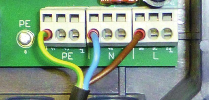
Multi-Channel Controller TOPAX® MC                                                                                                                                        Operating instructions

 Table of Contents
 1 Notes for the Reader...........................................................4                    10 Maintenance.....................................................................35
   1.1 General non-discrimination....................................................... 4                10.1 Maintenance intervals...........................................................35
   1.2 Explanation of the signal words................................................. 4                 10.2 Keeping logfiles....................................................................35
   1.3 Explanation of the warning signs............................................... 4                  10.3 Updating software................................................................35
   1.4 Identification of warnings.......................................................... 4             10.4 Battery.................................................................................35
   1.5 Identification of action instructions............................................ 4                10.5 Replacing the fuse................................................................36
                                                                                                          10.6 Resetting the settings...........................................................36
 2 Safety..................................................................................5              10.7 Finishing maintenance..........................................................37
   2.1 General warnings...................................................................... 5
   2.2 Hazards due to non-compliance with the safety instructions...... 5                              11 Troubleshooting TOPAX® MC............................................38
   2.3 Working in a safety-conscious manner...................................... 5
   2.4 Personnel qualification.............................................................. 5         12 Modbus addresses TOPAX® MC........................................39

 3 Intended use.......................................................................7                13 EU Declaration of Conformity............................................45
   3.1 Notes on product warranty........................................................ 7
   3.2 Intended purpose...................................................................... 7        14 Warranty claim..................................................................46
   3.3 Foreseeable misuse.................................................................. 7
                                                                                                       15 Glossary............................................................................47
 4 Product description............................................................8
   4.1 Scope of delivery...................................................................... 8       16 Index..................................................................................48
   4.2 Design and function.................................................................. 8
   4.3 multi-channel controller TOPAX® MC rating plate....................... 9

 5 Technical data...................................................................10
   5.1 Measuring inputs....................................................................10
   5.2 Output modules......................................................................10

 6 Dimensions.......................................................................11
   6.1 Outside dimensions................................................................11
   6.2 Drillhole dimensions...............................................................11

 7 Installation........................................................................12
   7.1 Principles...............................................................................12
   7.2 Installation on the wall............................................................12
   7.3 Electrical installation...............................................................12
   7.4 Terminal connection................................................................13
   7.5 Connecting sensors................................................................14
   7.6 Connecting the actors.............................................................15
   7.7 Digital inputs..........................................................................17
   7.8 RC protection for relay.............................................................17
   7.9 Connecting Ethernet...............................................................17
   7.10 RS485 interface....................................................................18

 8 Commissioning.................................................................19
   8.1 First steps...............................................................................19
   8.2 Configuration..........................................................................20
   8.3 Password protection...............................................................25
   8.4 Network settings.....................................................................26

 9 Operation...........................................................................27
   9.1 Confirming a message............................................................27
   9.2 Logbook.................................................................................27
   9.3 Configure trend display...........................................................28
   9.4 Manual mode..........................................................................28
   9.5 Calibration..............................................................................28
   9.6 Setpoints and reference sets...................................................32
   9.7 Access via network.................................................................34

© Lutz-Jesco GmbH 2020                                                                      BA-46020-02-V04                                                                Table of Contents
Subject to technical changes.                                                                                                                                                                     3
200123
Multi-Channel Controller TOPAX® MC Operating instructions
1 Notes for the Reader
This operating manual contains information and behaviour rules for the 1.3 Explanation of the warning signs
safe and designated operation of the multi-channel controller TOPAX®
MC. Warning signs represent the type and source of a danger:
Observe the following principles: Warning sign Type of danger
n Read the entire operating manual prior to starting-up the device.
n Ensure that everyone who works with or on the device has read the
General danger
operating manual and follows it.
n Maintain the operating manual throughout the service life of the de-
vice. Danger from electrical voltage
n Pass the operating manual on to any subsequent owner of the device.
1.1 General non-discrimination Danger from poisonous substances
In this operating manual, only the male gender is used where grammar
allows gender allocation. The purpose of this is to make the text easy to
Danger of damage to machine or functional
read. Men and women are always referred to equally. We would like to
influences
ask female readers for understanding of this text simplification.
Tab. 2: Explanation of the warning signs
1.2 Explanation of the signal words
Different signal words in combination with warning signs are used in this 1.4 Identification of warnings
operating manual. Signal words illustrate the gravity of possible injuries if Warnings are intended to help you recognise risks and avoid negative
the risk is ignored: consequences.
Signal word Meaning This is how warnings are identified:
Refers to imminent danger. Ignoring this sign may
DANGER!
lead to death or the most serious injuries. Warning sign SIGNAL WORD
Refers to a potentially hazardous situation. Description of danger.
WARNING! Failure to follow this instruction may lead to death Consequences if ignored.
or severe injuries.
ð The arrow signals a safety precaution to be taken to eliminate the
Refers to a potentially hazardous situation. danger.
CAUTION! Failure to follow this instruction may lead to
minor injury or damage to property.
1.5 Identification of action instructions
Refers to a danger which, if ignored, may lead to
PLEASE NOTE
risk to the machine and its function. This is how pre-conditions for action are identified:
Tab. 1: Explanation of the signal words ü Pre-condition for action which must be met before taking action.
@ A resource such as a tool or auxiliary materials required to perform
the operating instructions.
This is how instructions for action are identified:
è Separate step with no follow-up action.
1. First step in a series of steps.
2. Second step in a series of steps.
4 Result of the above action.
ü Action completed, aim achieved.
Notes for the Reader BA-46020-02-V04 © Lutz-Jesco GmbH 2020
4Multi-Channel Controller TOPAX® MC Operating instructions
2 Safety
2.1 General warnings 2.2 Hazards due to non-compliance with the safety
instructions
The following warnings are intended to help you eliminate the dangers
that can arise while handling the device. Risk prevention measures al- Failure to follow the safety instructions may endanger not only persons,
ways apply regardless of any specific action. but also the environment and the device.
Safety instructions warning against risks arising from specific activities The specific consequences can be:
or situations can be found in the respective sub-chapters.
n Failure of major unit und system functions.
n Failure of required maintenance and repair methods
DANGER!
n Risk to persons when working on the device
n Danger to the environment from overdosing
Mortal danger from electric shock!
Wrongly connected or located cables or damaged ones can injure you. 2.3 Working in a safety-conscious manner
ð Replace damaged cables without delay. Besides the safety instructions specified in this operating manual, further
ð Do not use extension cables. safety rules may apply. Always observe all safety-related regulations and
guidelines applicable at the product's location of use. Note in particular
ð Do not bury cables.
the following items:
ð Secure cables to avoid being damaged by other equipment.
n safety regulations on handling electricity and live components,
n safety regulations on handling hazardous substances,
n accident prevention regulations
n Safety and operating provisions,
WARNING!
n Environmental protection provisions,
n other applicable directives and laws.
Increased risk of accidents due to insufficient qualifica-
tion of personnel!
2.4 Personnel qualification
The device may only be installed, operated and maintained by person-
nel with sufficient qualifications. Insufficient qualification will increase Any personnel who work on the device must have appropriate special
the risk of accidents. knowledge and skills.
ð Ensure that all action is taken only by personnel with sufficient and Anybody who works on the device must meet the conditions below:
corresponding qualifications.
n Attendance at all the training courses offered by the owner,
ð Prevent access to the system for unauthorised persons. n Personal suitability for the respective activity,
n sufficient qualification for the respective activity,
n training in how to handle the device,
n knowledge of safety equipment and the way this equipment functions,
PLEASE NOTE
n knowledge of this operating manual, particularly of safety instructions
and sections relevant for the activity,
Do not dispose of the device in the domestic waste! n Knowledge of fundamental regulations regarding health and safety
and accident prevention.
Do not dispose of electric devices via the domestic waste.
All persons must generally have the following minimum qualification:
ð The device and its packaging must be disposed of in accordance
with locally-valid laws and regulations. n Training as specialists to carry out work on the device unsupervised,
n sufficient training that they can work on the device under the supervi-
ð Dispose of different materials separately and ensure that they are
recycled. sion and guidance of a trained specialist.
2.4.1 Specialist staff
Thanks to their professional training, knowledge, experience and knowl-
edge of the relevant specifications, specialist staff are able to perform the
job allocated to them and recognise and/or eliminate any possible dan-
gers by themselves.
© Lutz-Jesco GmbH 2020 BA-46020-02-V04 Safety
Subject to technical changes. 5
200123Multi-Channel Controller TOPAX® MC Operating instructions
2.4.2 Trained electricians
Due to their professional training, knowledge and experience as well as
knowledge of specific standards and provisions, trained electricians are
able to do the electrical work assigned to them and to recognise and
avoid any potential dangers by themselves.
They are specially trained for their specific working environment and are
familiar with relevant standards and provisions.
They must comply with the legally binding regulations on accident pre-
vention.
2.4.3 Trained persons
Trained persons have received training from the operator about the tasks
they are to perform and about the dangers stemming from improper be-
haviour.
Trained persons have attended all trainings offered by the operator.
2.4.4 Personnel tasks
In the table below, you can check what personnel qualifications are re-
quired for the respective tasks. Only people with appropriate qualifica-
tions are allowed to perform these tasks!
Qualification Activities
Transportation
Mechanical installation
Commissioning
Taking out of operation
Specialist staff
Fault rectification
Maintenance
Repairs
Disposal
Trained electricians Electrical installation
Trained persons Control
Tab. 3: Personnel qualification
Safety BA-46020-02-V04 © Lutz-Jesco GmbH 2020
6Multi-Channel Controller TOPAX® MC Operating instructions
3 Intended use
3.1 Notes on product warranty 3.3.3 Incorrect operation
n Protective equipment not functioning correctly or dismantled
Any non-designated use of the device can impair its function and the pro-
tection provided. This leads to invalidation of any warranty claims! n Unauthorised modification of the controller.
n Ignoring of alarm or error messages.
Please note that liability is on the side of the user in the following cases: n The elimination of alarm or error messages by insufficiently-qualified
n The device is operated in a manner which is not consistent with these personnel.
operating instructions, particularly safety instructions, handling in- n Bridging the external fuse
structions and chapter 3 “Intended use” on page 7. n Difficult operation due to insufficient lighting or poor access to the de-
n Information on usage and environment (section 5 “Technical data” on vice.
page 10) is not adhered to. n Operation not possible due to dirty or illegible display.
n If people operate the device who are not adequately qualified to carry
out their respective activities. 3.3.4 Incorrect maintenance
n Unauthorised changes are made to the device.
n Carrying out maintenance during ongoing operation
n No adequate or regular inspection of correct functioning
3.2 Intended purpose n No replacement of damaged parts or cables.
n No securing against reactivation during maintenance work
The controller monitors the current measured values during water treat-
ment and controls the dosing systems connected for water treatment. In n Use of the wrong spare parts.
this way, the controller ensures constant water parameters in various ap-
plications and can be deployed universally. One of its main applications is
to maintain the quality of water in public swimming pools and in industrial
applications by evaluating the measurements of a range of data including
chlorine value, pH value, Redox value, the total chlorine, conductivity and
the control of chlorinators.
3.3 Foreseeable misuse
The following section provides information regarding the device applica-
tions which are classified as non-intended use. This section is intended to
allow you to detect possible misuse in advance and to avoid it.
Foreseeable misuse is assigned to the individual stages of the product
lifetime:
3.3.1 Incorrect assembly
n Connecting the mains voltage without a protective earth
n Non-fused or non-standard mains voltage.
n Not possible to immediately or easily disconnect the power supply
n Wrong connecting cables for mains voltage
n Sensors and actors connected to the incorrect terminals or incorrectly
configured.
n Protective earth removed.
3.3.2 Incorrect start-up
n Commissioning with damaged or obsolete sensors.
n Commissioning without the establishment of all protective measures,
fastenings etc.
© Lutz-Jesco GmbH 2020 BA-46020-02-V04 Intended use
Subject to technical changes. 7
200123Multi-Channel Controller TOPAX® MC Operating instructions
4 Product description
4.1 Scope of delivery
Please compare the delivery note with the scope of delivery. The follow-
ing items are part of the scope of delivery:
n Multi-channel controller TOPAX® MC
n Operating instructions
n Mounting set
n Sensors (optional)
n Cable connection from the device to the sensors (optional)
4.2 Design and function
4.2.1 Functional diagram of a two-channel controller
Sensors Input modules Control system Output modules Actors
free Current pH / Distur-
Temp Controller 1 bance Module 1
chlorine module variable
Compensation
Disturbance
variable
On/Off Digital 1 Function
(External stop)
Virtual 1
(Effective chlorine)
pH pH Redox Temp Controller 2 Module 2
module
Compensation
Fig. 1: Functional diagram of a two-channel controller
Gap Field Description
1. Free chlorine
1. Measuring the free chlorine
2. Disturbance
Sensors 2. The disturbance variable is a variable flow volume which can be taken into account
variable
3. Measuring the pH value
3. pH value
1. Current module 1. Module for 4 − 20 mA signals and sensors with 24 V voltage supply
2. Digital 1 2. Digital input for the external control of a function (here: external stop)
Input modules
3. Virtual 1 3. Parameter calculated (here effective chlorine)
4. pH Redox module 4. Module for pH and Redox single-rod measuring cells
1. Controller 1 1. Controlling the free chlorine inc. pH/temperature compensation and disturbance variable
Control system
2. Controller 2 2. Controlling the pH value inc. temperature compensation
1. Module 1 1. Module on slot 1 to connect an actor (here: MAGDOS LD)
Output modules
2. Module 2 2. Module on slot 2 to connect an actor (here: MEMDOS LP)
Tab. 4: Explanation of functional diagram of a two-channel controller
Product description BA-46020-02-V04 © Lutz-Jesco GmbH 2020
8Multi-Channel Controller TOPAX® MC Operating instructions
4.2.2 Functions of the device 4.3 multi-channel controller TOPAX® MC rating plate
The stationary device measures the water parameters using sensors. There is information on the product about safety or the product's way of
Controlling actors such as dosing pumps controls the water parameters functioning. The information must stay legible for the duration of the ser-
to the desired setpoint. vice life of the product.
1
4.2.3 Main view
The main menu view will appear upon the start of the device or 5 minutes 2 7
after the last input. The main view shows the current values from up to
four sensors and further information.
1 2 6
4
3 5
3
Fig. 3: Multi-channel controller TOPAX® MC rating plate
Item Description
6
1 Product name
4 5
2 Technical specifications
Fig. 2: Main view with three sensors
Label showing conformity with applicable European
3
Item Function directives
1 Login/password settings 4 WEEE label
2 Date/time 5 Serial number
3 Measured values 6 Part number
4 Main menu 7 Month/year of manufacture
Tab. 6: Position numbers rating plate multi-channel controller TOPAX® MC
5 File Browser
6 Status row for messages
Tab. 5: Position numbers main view with three sensors
© Lutz-Jesco GmbH 2020 BA-46020-02-V04 Product description
Subject to technical changes. 9
200123Multi-Channel Controller TOPAX® MC Operating instructions
5 Technical data
TOPAX® MC
Housing dimensions (W x H x D) mm 302 x 240 x 107
Voltage supply 100 – 240 V AC, 50/60 Hz
Power consumption W max. 20
Analogue outputs for remote transmission 4 x 0/4 – 20 mA, working resistance max. 500 Ω
Disturbance variable input mA 0/4 – 20
Interfaces Ethernet TCP/IP or RS485 Modbus RTU (optional)
Protection class IP65
Ambient temperature °C -5 to +45 (no exposure to direct sunlight)
P, PI, PID or PD behaviour,
Control characteristic control direction selectable with disturbance variable feed forward,
2-side control selectable
Tab. 6: Technical data multi-channel controller TOPAX® MC
5.1 Measuring inputs
All measuring inputs consist of an input for temperature measurement via Pt100 and a second input for the measurement of a further water parameter.
On some measuring inputs, this input will measure a number of different parameters.
Measuring inputs (depending on version)
Number of measuring inputs up to 4
Amperometric 3-electrode measur-
mg/l 0 – 15 (dependant on the measuring cell transconductance)
ing cell with potentiostat (DMZ3.1)
Free chlorine
CS120 excess chlorine measuring cell mg/l 0 – 10 (dependant on the measuring cell transconductance)
Diaphragm-covered measuring cell mg/l 0 – 10 (dependant on the measuring cell)
Amperometric 3-electrode measur-
mg/l 0 – 15 (dependant on the measuring cell transconductance)
ing cell with potentiostat (DMZ3.1)
Chlorine dioxide
CS120 excess chlorine measuring cell mg/l 0 – 10 (dependant on the measuring cell transconductance)
Diaphragm-covered measuring cell mg/l 0 – 2 (dependant on the measuring cell)
Total chlorine Diaphragm-covered measuring cell mg/l 0 – 10 (dependant on the measuring cell)
pH value pH single-rod measuring cell pH 0 – 14 (dependant on the single-rod measuring chain)
Redox value Redox single-rod measuring cell mV 0 – 1000 (dependant on the single-rod measuring chain)
Conductive conductivity measuring cell inc.
Conductivity mS/cm 0 – 2, 0 – 20, 0 – 100
temperature sensor PT100, K = 1
Temperature Pt100 °C -10 to +90
Tab. 7: Multi-channel controller TOPAX® MC measuring inputs
5.2 Output modules
Output modules (depending on version)
2 x 230 V AC, 5 A (ohmic load)
Servomotor relay
kΩ Potentiometer feedback: 1 – 10
Constant 0/4 – 20 mA output
Servomotor 20 mA
Servomotor with 20 mA feedback
Relays 2 x 230 V AC, 5 A (ohmic load)
Optocoupler 2 x 80 V DC, 5 mA
Tab. 8: Multi-channel controller TOPAX® MC output modules
Technical data BA-46020-02-V04 © Lutz-Jesco GmbH 2020
10Multi-Channel Controller TOPAX® MC Operating instructions
6 Dimensions
All dimensions in mm
6.1 Outside dimensions 6.2 Drillhole dimensions
All dimensions in mm All dimensions in mm
302 267
240
171
Fig. 4: Outside dimensions Fig. 5: Drillhole dimensions
© Lutz-Jesco GmbH 2020 BA-46020-02-V04 Dimensions
Subject to technical changes. 11
200123Multi-Channel Controller TOPAX® MC Operating instructions
7 Installation
7.1 Principles
DANGER!
Make sure that the installation location complies with the following re-
quirements:
Mortal danger from electric shock!
n The display is easily accessible and is visible.
Improperly installed or damaged components in the electronics instal-
n Plan to leave min. 20 cm free space for the installation of the cable
lation can cause injury.
underneath the device. You must be able to install the cable without
kinking or damage. ð Ensure that all work on the electrical installation is performed by a
n Various lines (e.g. voltage supply, data cable and sensitive lines for
qualified electrician.
measuring purposes) must be installed separately. The different lines ð Ensure that all work on the electrical installation is performed in a
should only cross at 90° so as to prevent falsifications. de-energised state.
n Electrical, magnetic and electromagnetic fields affect signal transmis- ð Ensure that the power supply is secured with a fault current prote-
sion and can destroy electronic components. ctive circuit.
n Compliance with the permissible ambient temperatures (see section 5
ð Replace damaged cables or components without delay.
“Technical data” on page 10).
7.2 Installation on the wall Perform the following work steps:
Resources required: 1. Fit wire end sleeve to the cable ends if the supply cable does not
have them.
@ Assembly kit
2. Open the device housing.
@ Drill
3. Lead the supply cable through a cable screw connection to the un-
@ Slotted screwdriver derside of the device.
4. Turn the cable screw connection union nut until the line is fixed in the
Perform the following work steps:
screw connection so that the screw connection performs strain relief.
1. Drill the four drillholes for wall mounting. The exact dimensions are Ensure that the feed cable is installed loosely.
stated in section 6 “Dimensions” on page 11. 5. Connect the voltage supply to the clamps 44 − 52. Observe the divi-
2. Unscrew the screw on the right-hand side of the device and pull out sion into protective earth (PE), neutral conductor (N) and the phase (L)
the rod. on the circuit board.
4 You can now open the device.
3. Open the device and use the screws for wall mounting. Ensure that
the device is secured to the wall.
4. Close the device again using the rod.
ü The device is fitted on the wall.
7.3 Electrical installation
The voltage supply to your device can now be performed via a normal
Schuko plug or a control cabinet. Perform the specifications of this sec-
tion for devices without a pre-fitted Schuko plug. Fig. 6: Connected voltage supply
Pre-conditions for actions:
ü Electrically installation
ü The device was installed in accordance with section 7.2 “Installation
on the wall” on page 12. Only 3 of 9 clamps are required for connection of the voltage
ü A voltage supply with 100 − 240 V AC (50/60 Hz) is available. i supply. You can use the free clamps to supply further devices
with voltage.
ü The voltage supply is deactivated before the start and secured
against reactivation. The contact load rating amounts to max. 4A.
ü The housing is open.
Resources required:
@ Schuko plug
@ Wire end sleeves 0.75 − 2.5 mm²
Installation BA-46020-02-V04 © Lutz-Jesco GmbH 2020
12Multi-Channel Controller TOPAX® MC Operating instructions
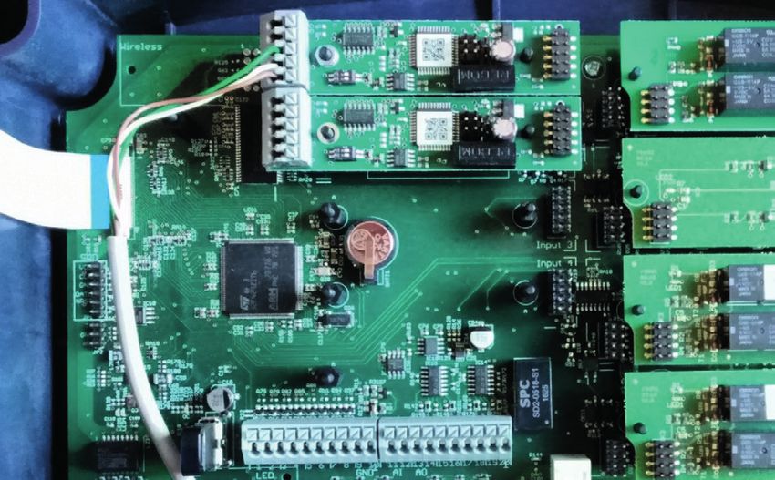
7.4 Terminal connection
Input 1
Output 1
Input 2
Output 2
Input 3
Input 4
Output 3
USB LED outputs 0/4 – 20 mA
1 2 3 4 5 6 7 8 9 10 11121314151617181920 Output 4
Ethernet Digital inputs
37383940 A B 2122232425262728 2930313233343536
Alarm relay
41 42 43 44 45 46 47 48 49 50 51 52
RS485 Voltage
Fig. 7: Overview of terminal connection
Terminal Function Description
1 LED output 1 (red) +
2 LED-output 1 (green) +
3 LED output 2 (red) +
4 LED-output 2 (green) + 5 V with 220 Ω series resistance for LEDs of the water
5 LED output 3 (red) + sampling stations
6 LED-output 3 (green) +
7 LED output 4 (red) +
8 LED-output 4 (green) +
9 − 10 LED output GND - Ground for the LEDs
11 +
Disturbance variable input 0/4 − 20 mA
12 -
13 +
Analogue output 1
14 -
15 +
Analogue output 2
16 -
0/4 – 20 mA, working resistance max. 500 Ω
17 +
Analogue output 3
18 -
19 +
Analogue output 4
20 -
+ (odd numbers)
21 − 36 Digital inputs 1 − 8 Function configurable
- (even numbers)
37 − 40 Ethernet connection
Clamps 41 + 42 normal on
41 − 43 Alarm relay
Clamps 42 + 43 normal off
44 − 46 Protective earth (PE)
47 − 49 Connection supply voltage Neutral line (N)
50 − 52 Phase (L)
Tab. 7: Terminal connection
© Lutz-Jesco GmbH 2020 BA-46020-02-V04 Installation
Subject to technical changes. 13
200123Multi-Channel Controller TOPAX® MC Operating instructions
7.5 Connecting sensors 7.5.1 pH Redox module input circuit board
1
DANGER! 2
3
4
Mortal danger from electric shock!
Fig. 8: pH Redox module input circuit board
Live parts can inflict fatal injuries.
ð Disconnect the external power supply before opening the water Terminal Function Sensors
sampling station or the TOPAX® MC controller.
1 Temperature input Resistance thermometer
ð Secure the station to prevent it from being switched on again!
2 Temperature input TE110/Pt100
Up to four input modules can be connected to the device. A water param-
3 - (wire with Ø 1.5 mm) pH single-rod measuring
eter and the temperature can be measured with every module.
chain PE110/Redox
Pre-conditions for actions: 4 + (wire with Ø 2 mm) single-rod measuring chain
ME110
ü The voltage supply has been disconnected and protected against
Tab. 8: Terminal connection of the pH Redox module input circuit board
re-connection.
ü The housing is open. Ø2
Centre conductor
Resources required: Ø 1,5
Screen
@ Sensors Fig. 9: Connect the cable from the pH or Redox single-rod measuring chain correctly
@ Suction connection
7.5.2 Potentiostat module input circuit board
Perform the following work steps:
1. Lead the cable through one of the cable screw connections on the 1
underside into the interior of the housing. 2
3
2. Connect the wires onto the clamp block of the input modules. Comply 4
with the terminal plans in the following sections. 5
Fig. 10: Potentiostat module input
ü Sensor connection completed.
Terminal Function Sensors
PLEASE NOTE
1 Temperature input Resistance thermometer
Electronic distortion of the measurement results. 2 Temperature input TE110/Pt100
Incorrect installation of the electrical cables can distort the measure- 3 Measuring electrode
ment results. As a result, the control of connected devices can be faulty.
ð Do not route the connecting cable parallel to the mains and control 4 Counter electrode 3 electrode potentiostat
connections, and always with a clearance of at least 15 cm. Lay
5 Reference electrode
connection junctions at an angle of 90°.
Tab. 9: Terminal connection of the potentiostat module input circuit board
Installation BA-46020-02-V04 © Lutz-Jesco GmbH 2020
14Multi-Channel Controller TOPAX® MC Operating instructions
7.5.3 Current module input circuit board 7.6 Connecting the actors
A number of sensors require an operating voltage for their measurement. Depending on the equipment of the device, you have various possibilities
These sensors are connected to the current module and supplied with 24 of actuating actors such as dosing pumps or regulation valves.
V.
7.6.1 Alarm relay
Bild BA1 Eingangsmodul Leitfähigkeit The alarm relay on the main board forwards alarms.
2
3
TOPAX MC Salzgehalt
4
5
79889_1 41 42 43
Fig. 11: Current module input circuit board
Fig. 13: Alarm relay
Terminal Function Sensors
1 Temperature input Terminal Function Description
Resistance thermometer
TE110/Pt100 The relay works on these
2 Temperature input 41 + 42 normal on
clamps as an opener.
3 - - Excess chlorine measuring The relay works on these
42 + 43 normal off
cell CS120/conductivity clamps as a closer.
+ for CS120** measuring cell Tab. 13: Terminal connection of the alarm relay
4
- for 0/4 − 20 mA Total chlorine measuring cell
GCM/diaphragm-covered 7.6.2 Output circuit board with relay
measuring cell Cl 4.1/
5 + 24 V DC output diaphragm-covered 4
measuring cell CD 4 MA* 3
Tab. 10: Terminal connection of the current module input circuit board 2
1
* Requires 24 V supply module
Fig. 14: Output circuit board with relay
**red: +; blue, purple: -
7.5.4 Conductivity module (conductive) input circuit board Terminal Function Description
1
4 Relay X.2 Second digital output
3 2
2
1 3
Relay X.1 First digital output
4
Fig. 12: Conductivity module (conductive) input circuit board
Tab. 14: Clamp connection of the output circuit board with relay
Termi- Function Sensors Wire colour M12
nal connection cable Actors Configuration
1 Temperature input black (BK) MAGDOS dosing pumps On/Off
2 Temperature input Conductivity blue (BU)
MEMDOS dosing pumps On/Off
3 Conductivity measuring brown (BN)
measurement input (conductive), MEMDOS SMART dosing pumps On/Off
k=1
4 Conductivity white (WH) MIDIDOS/MINIDOS dosing pumps On/Off
measurement input
Peristaltic pumps Pulse length
Tab. 11: Clamp connection conductivity module (conductive) input circuit board
Tab. 15: Actors and relay configuration
DIP switch 0 – 2000 μS/cm 0 – 20 mS/cm 0 – 100 mS/cm
1 OFF ON ON
2 OFF ON ON
3 OFF OFF ON
4 OFF OFF ON
Tab. 12: Selecting the measuring range
© Lutz-Jesco GmbH 2020 BA-46020-02-V04 Installation
Subject to technical changes. 15
200123Multi-Channel Controller TOPAX® MC Operating instructions
7.6.3 Output circuit board (optocoupler) 7.6.5 Output circuit board with servomotor 20 mA
The output connects a servomotor with or without feedback.
4
3
2
1 3
2
1
Fig. 15: Output circuit board with optocoupler
Terminal Function Description Fig. 17: Output circuit board with servomotor 20 mA
1 +
Optocoupler x 2 Second digital output Terminal Function Description
2 -
1 - GND
3 +
Optocoupler x 1 First digital output 2 Input (feedback) 4 − 20 mA
4 -
3 Output 4 − 20 mA
Tab. 16: Clamp connection of the output circuit board with optocoupler
Tab. 20: Clamp connection of the output circuit board with servomotor 20mA
Actors Configuration
Actors Configuration
MAGDOS dosing pumps
Servomotor with 20 mA/
MEMDOS dosing pumps Pulse frequency Chlorine gas control valve C 7700
continuous output (20 mA)
MEMDOS SMART dosing pumps EASYZON chlorine dioxide system
Tab. 17: Actors and configuration optocoupler
MAGDOS dosing pumps
Continuous output (20 mA)
7.6.4 Servomotor relay output circuit board MEMDOS dosing pumps
This output is suitable for connecting a servomotor with or without feed- MEMDOS SMART dosing pumps
back via a potentiometer from 1 – 10 kΩ. Tab. 21: Actors and configuration servomotor 20 mA
7.6.6 Testing the outputs
6 3 You can use manual mode to test the correct connection of an actor.
5 2 Take the alarm chain into account before conducting the test and inform
4 1 any connection points or interrupt the alarm chain for the period of the
test.
Test the connected actors
Fig. 16: Servomotor relay output circuit board
Pre-conditions for actions:
Terminal Function Description ü The actors have been connected in accordance with section 7.6
“Connecting the actors” on page 15.
Opening the regulation
1−2 Relay output ü The device housing cover is closed.
valve
2−3 Closing the regulation valve Relay output
ü The voltage supply has been established and the device has been
switched on.
0%
4
Perform the following work steps:
5 Feedback via potentiometer
1. Working in the main menu, navigate to “Manual mode” (see section
6 100% 9.4 “Manual mode” on page 28).
Tab. 18: Clamp connection of the output circuit board with servomotor relay 4 You will now see all the outputs.
2. Select the output to which you have connected the actor and which
Actors Configuration you wish to test.
Servomotor with potentiometer/ 3. Enter a value between 0 and 100 % and check whether the actor re-
Chlorine gas control valve C 7700 acts as desired.
servomotor without potentiometer
ü Actor has been tested.
Tab. 19: Actors and configuration servomotor relay
Installation BA-46020-02-V04 © Lutz-Jesco GmbH 2020
16Multi-Channel Controller TOPAX® MC Operating instructions
Testing the analogue outputs 7.9 Connecting Ethernet
You can also test the connection of terminals 13 to 20. You can use the Ethernet connection for the following actions:
n Reading/writing via Modbus TCP/IP protocol (PLC or Computer)
Pre-conditions for actions:
n Access via web browser
ü The device housing cover is closed.
n Access via TFTP server
ü The voltage supply has been established and the device has been The device is fitted with a network input in the form or a 4-pole and
switched on. D-coded M12x1 socket. Lutz-Jesco GmbH offers different lengths of spe-
cial twisted-pair network cables to make the typical Ethernet RJ-45 plug
Perform the following work steps: connection. If you use third-party cables, choose a Category 5 cable with
1. Working in the main menu, navigate to System > Outputs > Ana- an impedance of 100 Ω or above.
logue.
4 You will now see all analogue outputs (terminals 13 − 20). Pin Assignments Wire colours
2. Press “Test signal”. 1 TX- yellow
3. Set the mA value. 2 TX+ orange
4. Press "Start”.
3 RX- white
ü Analogue outputs tested.
4 RX+ blue
- Screen -
7.7 Digital inputs Tab. 22: Ethernet connection socket
You can use up to 8 digital inputs to evaluate switching statuses and to
detect them as alarm message which are to be documented in the log-
book.
Further information about the settings of the digital inputs can be found in
section 8.2.1.6 “Digital inputs” on page 22.
7.8 RC protection for relay
Fig. 18: Ethernet connection
When connecting to the relays, note that inductive loads must be sup-
pressed. If this is not possible, the relay contact on the device terminal Installing a wired network
must be protected by an RC protective circuit / interference suppression
During installation, comply with the following points:
element.
n The Ethernet is cabled in a star topology. The maximum cable length
If devices with inductive loads from a nominal current of 1 A are connect- is 100 m
ed to a relay, the contacts in the relay may become bonded. Thus, the de- n Only use screened cables and connectors
vice will operate in an uncontrolled manner. To prevent bonding if the load n Only use CAT5 cables or better
circuit suffers a short-circuit, the relays must be protected separately on
the maximum relay switching current.
Pre-conditions for actions:
ü You would like to connect an inductive load to the relay.
Perform the following work steps:
1. Switch off the device.
2. Clamp the interference suppression element parallel to the inductive
load.
3. Should it prove impossible to perform point 2, clamp the interference
suppression element parallel to the relay output.
ü RC protection for relay connected.
© Lutz-Jesco GmbH 2020 BA-46020-02-V04 Installation
Subject to technical changes. 17
200123Multi-Channel Controller TOPAX® MC Operating instructions
7.10 RS485 interface
ON OFF
A B A B
Fig. 19: Jumper position on RS485
When using multiple devices on a data line you, must activate
i a 120 Ω resistance on the last device. You can activate the re-
sistance by setting the jumper to “ON” as shown in Fig. 19
“Jumper position on RS485” on page 18.
Your device can have an optional RS485 interface. Using a second data
cable you can connect up to 14 devices with a PC or a PLC. Modbus RTU
protocol serves as a protocol for data transfer. You can use the addresses
1 to 14. The addresses 0 and 15 are reserved for internal purposes and
are not supported.
RS485 Modbus settings:
n Baud rate: 9600
n Word length: 8 Bit
n Stop bit: 1 Bit
n Parity: None
n You can read out a maximum of 40 addresses at once.
The list of Modbus commands can be found in section 12 “Modbus ad-
dresses TOPAX® MC” on page 39.
Perform the following work steps:
1. Open the device housing.
2. Connect a two-wire cable to terminals A and B of the RS485 module.
3. Connect the device with your network.
ü Device connected with network.
Installation BA-46020-02-V04 © Lutz-Jesco GmbH 2020
18Multi-Channel Controller TOPAX® MC Operating instructions
8 Commissioning
Outputs
Optocoupler
Servomotor
Servomotor Controller functions Behaviour
Relays
20 mA
relay
n The output switches if a value is exceeded.
x On/Off
n Hysteresis can be set from 0,1 – 50 %
n Relay: 10 – 100 pulses per minute
n Optocoupler: 10 – 350 pulses per minute
Pulse frequency n The pulse frequency is dependant on the control deviation and the set control
x x
2-sides pulse frequency parameters.
n With a control output power of Y = 25 % and a maximum pulse frequency of 100
pulses/min., the controller would output 25 pulses/min.
n 0 – 3600 seconds cycle duration
n Relay output (e. g. for solenoid valve)
Pulse length n Depending on the control deviation and the defined control parameters, the relay
x
2-sides pulse length pulls in or drops out for the set cycle duration. If the cycle lasts 30 seconds and the
controller output power is 40 % the relay applies for example for 12 seconds,
followed by 18 seconds of non-application.
n A feedback potentiometer can be connected (1 – 10 kΩ) for servomotors with
Servomotor with a position feedback.
x
feedback potentiometer n Compensate the feedback potentiometer. During compensation, the servomotor is
first started and then stopped automatically.
Servomotor without a n For servomotors without feedback.
x
feedback potentiometer n Measure and set the runtime of the servomotor.
x Continuous output n Continuous control output from 0/4 – 20 mA for the actuation of constant actors.
Servomotor with 20 mA n Servomotors which are controlled via 0/4 – 20 mA and have a 0/4 – 20 mA
x
feedback position feedback.
Tab. 23: Functions of the individual controllers
8.1 First steps Pre-conditions for actions:
ü The device has been installed in accordance with section 7 “Installa-
tion” on page 12.
PLEASE NOTE
Configuration assistant
Distorting the measurement results
With initial commissioning, a configuration wizard will lead you through
The measurement results of high-impedance sensor inputs may be the basic settings: Your preferred language, the measured values, control-
distorted in the first 24 hours due to the heat development inside the ler assignments and switch outputs. With the exception of the language,
housing of the TOPAX® MC controller. the values configured here can only be set in the configuration assistant.
ð Activate the TOPAX® MC controller 24 hours before start-up. The finer settings are made in the sub-menus.
ð Factor in the distortion caused by the heat development and only Working in the configuration assistant, determine the tasks of the in-
perform the calibration for the measurement results 24 hours after stalled modules, the controller and the output modules.
activating the TOPAX® MC controller.
The finer settings such as the behaviour of these modules are made later,
e. g in the “Outputs” menu item.
You need to make a number of basic settings before operating the device. Perform the following work steps:
This section leads you through initial commissioning.
1. Set the preferred language and press on the arrow.
2. Measured values: Determine the desired measured value for the in-
stalled input modules. Press the right-hand arrow.
© Lutz-Jesco GmbH 2020 BA-46020-02-V04 Commissioning
Subject to technical changes. 19
200123Multi-Channel Controller TOPAX® MC Operating instructions
3. Controller: You can assign inputs for up to four controllers in this tab. 8.2.1.2 Temperature inputs
Select a sensor, a virtual input or a timer. Set the centre row of the
control function (Tab. 23 “Functions of the individual controllers” on You can connect up to four temperature sensors (depending on the ver-
page 19) and press the right-hand arrow. Controllers 1 to 4 must sion) to the device. This enables you to measure the temperatures at vari-
be assigned to the output modules 1 to 4 in a fixed fashion. ous positions.
4. Digital outputs: You can assign a function to output modules in this
Perform the following work steps:
tab. Only the output modules which are still free are displayed. Press
the right-hand arrow. 1. In the main menu under System > Inputs, navigate to the “Tempera-
5. Confirm the security query with “Yes” to save the configuration. ture” tab.
The configuration assistant has been ended. 2. In the “Temperature” tab, configure every connected temperature
ü sensor and state the following information.
Start the configuration assistant manually in System > Set-
i tings > Configuration > “Configuration assistant”.
3. Measurement: Chose between “On” and “Off”.
4. Min-alarm: Activate or deactivate the minimum alarm and state a
temperature under which the alarm will be triggered.
5. Max-alarm: Activate or deactivate the maximum alarm and state a
8.2 Configuration temperature over which the alarm will be triggered.
The device is set up variably and can be individually adapted to meet your ü Configuration of the temperature sensors completed.
requirements. As such, it is necessary to adjust the configuration of the
inputs and outputs to the sensors and actors used.
8.2.1.3 Compensation of cross sensitivities
The following section leads you through the device configuration.
The water parameters which you measure with the device can be falsi-
8.2.1 Inputs fied by interference (e. g. with temperature or pH value).
The device can compensate these interferences automatically.
You can connect up to four sensors (depending on model) for various wa-
ter parameters and the temperature to the device. You can also use up to Perform the following work steps:
eight digital inputs (depending on the version).
1. Working in the main menu under System > Inputs, navigate to the
8.2.1.1 Sensor inputs “Compensation” tab.
2. Working in the “Compensation” tab, configure every sensor connect-
The sensors in the device must be configured individually to enable pre- ed for which the measured value is to be compensated and state the
cise and error-free measurement of the water parameters. You can per- following information
form various settings. 3. Temperature: If it is possible to compensate for the influence of the
temperature, you can select a fixed reference value or one of the four
Perform the following work steps:
temperature inputs.
1. In the main menu, navigate from System > Inputs to the “Sensors” 4. pH value: If it is possible to compensate for the pH value error, you
tab. can select a fixed reference value or a sensor input.
2. In the “Sensors” tab, configure every connected sensor and state the
ü Configuration of the compensation completed.
following information.
3. Input: Select the input module of the sensor which you wish to con-
figure.
4. Signal: Enter the type of the sensor signal. Depending on the input
module, the signal type has been specified or you can select a signal
type.
5. Measurement: Here, you can check which water parameters are
measured. This setting can only be changed in the configuration as-
sistant.
6. Unit: Select the appropriate unit.
7. Measuring range: If an input field is available, enter the measuring
range of the sensor.
8. Min-alarm: Activate or deactivate the minimum alarm and state a
value under which the alarm will be triggered.
9. Max-alarm: Activate or deactivate the maximum alarm and state a
value over which the alarm will be triggered.
10. Delay: Set a time delay for the “minimum and maximum alarm”.
ü Configuration of the sensors completed.
Commissioning BA-46020-02-V04 © Lutz-Jesco GmbH 2020
20Multi-Channel Controller TOPAX® MC Operating instructions
8.2.1.4 Disturbance variable Combined chlorine
You can connect the measurement of a disturbance variable (e.g. a flow Bound chlorine is calculated from the difference between the total chlo-
volume) to an analogue 4 – 20 mA input. The disturbance variable can rine and the free chlorine:
then be taken into account with a factor (0.1 to 10) during the calculation
of the control variable Y. The control variable Y will be multiplied with the Bound chlorine = total chlorine – free chlorine
disturbance variable during the calculation.
At least one total chlorine measurement is required to calculate bound
Example: If the factor = 2 and the disturbance variable amounts to 42 %, chlorine. The chlorine value can be entered manually as a single refer-
the controller can be set to a maximum of the control variable Y = 84 %. If ence value or a corresponding sensor input is selected.
the factor = 0.5 and the disturbance variable amounts to 42 %, the con-
troller can be set to a maximum of the control variable Y = 21 %. Perform the following work steps:
Perform the following work steps: 1. Working in the main menu under System > Inputs, navigate to the
“Virtual” tab.
1. Working in the main menu under System > Controller, navigate to the 2. Working in the “Virtual” tab, configure the desired calculation of the
“Disturbance variable” tab and state the following information. bound chlorine and state the following information.
2. Disturbance variable: Set the disturbance variable to an input signal 3. Calculation: Select “bound chlorine” to calculate the bound chlorine.
of 4 – 20 mA or 0 – 20 mA. You can also deactivate the disturbance
4. Total chlorine: Select the sensor which measures the total chlorine.
variable.
5. Free chlorine: Select the sensor which measures the free chlorine. If
3. Unit: As a rule, the disturbance variable is the measurement of a
no sensor is present, you can enter a reference value measured once
flow. Select the desired unit.
which can be used for the calculation.
ü Configuration of the disturbance variable input completed. 6. Min-alarm: Activate or deactivate the minimum alarm and state a
value under which the alarm will be triggered.
8.2.1.5 Virtual inputs 7. Max-alarm: Activate or deactivate the maximum alarm and state a
value over which the alarm will be triggered.
You can calculate a new value from multiple measurements or reference 8. Delay: Set a time delay for the minimum and maximum alarm.
values using a virtual input. You can assign the new virtual value to a con-
troller in the configuration assistant. ü Configuration of the bound chlorine completed.
In this way, you can calculate the difference between the bound chlorine Effective chlorine
and the effective chlorine and use it as the basis for controlling your ac-
tors. The disinfectant effect of the free chlorine is highly dependant on the pH
value of the process water. The pH value influences the reactivity of the
Difference Chlorine ions. This relationship is underscored by the dissociation curve
(Fig. 20 “Dissociation curve of the effective chlorine” on page 22) of
You can calculate the difference between two measured values or the dif- the chlorine.
ference between a measured value and a fixed reference value.
The actual disinfectant effect of the chlorine is generated by the hy-
Perform the following work steps: pochlorous acid (HClO). The figure shows that the proportion of the HClO
1. Working in the main menu under System > Inputs, navigate to the is largest between pH 2 and pH 7.5. The disinfectant effect is very low
“Virtual” tab. outside this pH value.
2. State the following information. For photometric measurements the pH value of the sample is buffered to
3. Calculation: Select “difference”. approx. pH 6.5. As a result the measurement has a higher effective chlo-
rine content than is actually in the process water. For high pH-values sig-
4. Select a sensor. nificant differences will therefore occur between the expected and actual
5. Select a second sensor or a reference value. The second sensor must disinfection if assessed by photometric analysis. The calculation of the ef-
output the same measured value as the first. You will need to enter fective chlorine can be used to display the proportion of the hypochlorous
the reference value manually. acid (HCIO), i.e. the proportion which contributes to the disinfectant effect.
6. Min-alarm: Activate or deactivate the minimum alarm and state a
difference value under which the alarm will be triggered.
7. Max-alarm: Activate or deactivate the maximum alarm and state a
difference value over which the alarm will be triggered.
8. Delay: Set a time delay for the minimum and maximum alarm.
ü Configuration of the difference completed.
© Lutz-Jesco GmbH 2020 BA-46020-02-V04 Commissioning
Subject to technical changes. 21
200123Multi-Channel Controller TOPAX® MC Operating instructions
8.2.1.6 Digital inputs
100 % -..
'" .,,.. -----
HCIO
..... ' -..
CIO-
-· You can use up to 8 digital inputs to evaluate switching statuses and to
X
/
/
' \// / detect them as alarm message which are to be documented in the log-
book.
50 I \ �
I \ I \
I \ I \ Perform the following work steps:
I 1 I \
1
I
I 1
I \
\
1. In the main menu under System > Inputs, navigate to the “Digital”
I
I 1 I \ tab.
10 1 1
I 1
I 1 I \ 2. In the “Digital” tab, configure the inputs and state the following infor-
I 1 I \
5 1 \ mation.
I I
1
3. Action: Choose between “OK = open” (N.O., working contact) or “OK
I I \
I 1 I \
I 1 I \ = contact” (N.C., break contact).
I 1 I \
I 1 I \ 4. Function: Select a function from Tab. 23 “Functions of the individual
I 1 I \
1 1
1 1
controllers” on page 19 depending on the desired reaction of the
I 1 I \ device to the input.
I 1 I \
0,5 I
Configuration of the digital inputs completed.
I 1 1
I 1
1
I \
\
ü
I I
1 I \
I \
I 1 I
I 1 I \
\
Function Reaction
0,1 1 1 I
0 2 4 6 8 10 12 14 The switching of the contact has no influence
(pH) Off
on the measurement or control.
pH > 1,7 : Cl2 + H2O � HCIO + HCI
pH > 7,5 : HCIO � H + + CIO- You can use the contact to switch between
Setpoint changeover
Fig. 20: Dissociation curve of the effective chlorine reference sets.
Measuring water
Perform the following work steps: All controller outputs will be switched off.
shortage
1. Working in the main menu under System > Inputs, navigate to the External stop All controller outputs will be switched off.
“Virtual” tab.
2. Working in the “Virtual” tab, configure the desired calculation of the Pre-alarm 1 – 4
Only display as an alarm message. Nothing is
effective chlorine and state the following information. switched off.
3. Calculation: Select “effective chlorine” to calculate the effective The appendant controller output is switched
Main alarm 1 – 4
chlorine. off. The other outputs remain unaffected.
4. Free chlorine: Select the sensor which measures the free chlorine. You can assign an individual name to this
5. pH value: Select the sensor which measures the pH value. If no sen- digital input. The name is displayed in the
sor is present, you can enter a reference value measured once which Others
alarm messages during switching the
can be used for the calculation. contacts.
6. Temperature: A temperature value is required to calculate the effec- Tab. 24: Functions digital inputs
tive chlorine. Select the temperature input which can be used for the
calculation. If no temperature sensor is present, you can set a refer-
ence value measured once which can be used for the calculation.
8.2.2 Outputs
7. Min-alarm: Activate or deactivate the minimum alarm and state a Depending on the equipment, you can connect a range of actors to the
value under which the alarm will be triggered. device and actuate them. Make sure that you actuate the actor with the
8. Max-alarm: Activate or deactivate the maximum alarm and state a correct signal type and select an appropriate output module with the con-
value over which the alarm will be triggered. figuration. An alarm relay, four analogue outputs and the possibility of
9. Delay: Set a time delay for the “minimum and maximum alarm”. connecting external LEDs (e.g. for water sampling stations) are always
available.
ü Configuration of the calculation of the effective chlorine
completed. 8.2.2.1 Controller outputs
You can configure and use up to four controllers.
Pre-conditions for actions:
ü You have used the configuration assistant to assign an input and a
control function to a controller (see section “Configuration assistant”
on page 19).
Commissioning BA-46020-02-V04 © Lutz-Jesco GmbH 2020
22Multi-Channel Controller TOPAX® MC Operating instructions
Perform the following work steps: 2. Working in the “Parameter” tab, configure every control channel and
state the following information.
1. Working in the main menu under System > Outputs, navigate to the
3. Control direction: Configure the direction of control. If a switch is to
“Controller” tab.
be made between a 1- and a 2-side control, this must be set in the
2. Working in the “Controller” tab, configure the controller output and configuration assistant.
state the following information.
4. Function: Set the desired controller function. Possible: P-, PI-, PD-
3. Y-alarm: Activate the Y alarm. The Y alarm is a safety cut-out. If the and PID-controller.
controller output power amounts to more than 95 % (e.g. through a
5. Xp, Tn, and Tv: You can configure these parameters depending on
malfunction) over the set time, the Y alarm will be triggered and the
the control function that has been set.
corresponding controller output will be set to 0 %. You can set a time
between 0 and 200 minutes. 6. Disturbance variable and factor disturbance variable: If you have
activated a disturbance variable (see chapter 8.2.1.4 “Disturbance
4. Basic load: Depending on the controller function, you can set a base
variable” on page 21), you can configure the influence of this dis-
load which is always active independently of the control variable.
turbance variable on the selected controller channel. You can switch
With a base load of 10 %, the actor is always actuated with a mini-
the influence on or off and set a factor between 0.1 and 10.
mum of 10 %.
5. Limit: Depending on the controller function, you can set a limit of be- ü Configuration of the controller parameters completed.
tween 5 – 100 %. State the value at which the actor should be actu-
ated as maximum.
8.2.2.4 Digital output signals
6. Further settings are dependant on the function of the controller. Fur-
ther information is available in Tab. 23 “Functions of the individual You can use digital output signals via the outputs of the alarm relay, an
controllers” on page 19. optocoupler circuit board or a relay circuit board. The following sections
describe the configurations that you can perform.
ü Configuration of the controller outputs completed.
Alarm relay as an alarm output.
8.2.2.2 Actuation via a timer You can use the alarm relay (terminals 41 – 43) on the main board as an
output for alarm messages.
The output can be used for direct actuation via a timer. This is required
e.g. to run the flocculant pump or the peristaltic pumps over a certain Perform the following work steps:
time.
1. In the main menu under System > Outputs, navigate to the “Digital”
Pre-conditions for actions: tab.
2. Working under “Digital output”, select the “alarm relay” output.
ü You have assigned the "Timer switch" input to a controller using the
configuration wizard as described in the chapter 8.1 “First steps” on 3. Configure the alarm relay by entering the following data.
page 19. 4. Action: Choose between “normal opened” (N.O., make contact) or
“normal closed” (N.C., break contact).
Perform the following work steps:
5. Latching: “On “= the alarm relay is active until all alarms have been
1. Working in the System menu, navigate to > Outputs and configure manually confirmed. “Off” = the relay is automatically deactivated if
the output (see section 8.2.2 “Outputs” on page 22). the active alarms are no longer pending.
2. Navigate to the menu > setpoints. Here, you can set the desired set 6. Output triggers upon: Select which alarms should trigger the alarm
control output directly from 0 to 100 %. relay. The relay switches as soon as one of the selected alarms is ac-
tive.
3. Reference set: Here, you can set various control outputs and via the
timers in the “Switching” tab, you can determine when the control 7. Alarm delay: Determine the earliest point (in seconds) at which the
output should be changed. The checkmark must be set against relay should switch after activation of the alarm.
“Switch setpoints automatically”. Further information pertaining to
ü Configuration of the alarm relay completed.
switching is found in section 9.6 “Setpoints and reference sets” on
page 32.
Further alarm outputs
ü Actuation configured via a timer.
In addition to the alarm relay, you can use the unused outputs of the opto-
coupler circuit board or relay circuit boards for further alarm messages.
8.2.2.3 Controller parameters
Pre-conditions for actions:
You can configure the behaviour of the individual controller channels. Ex-
planations of the various functions can be found in Tab. 23 “Functions of
ü You have used the configuration assistant to assign the “alarm out-
put” function to a free output (see section “Configuration assistant”
the individual controllers” on page 19 and in section 15 “Glossary” on on page 19).
page 47.
Perform the following work steps:
Perform the following work steps:
1. In the main menu under System > Outputs, navigate to the “Digital”
1. Working in the main menu under System > Controller, navigate to the
tab.
“parameter” tab.
© Lutz-Jesco GmbH 2020 BA-46020-02-V04 Commissioning
Subject to technical changes. 23
200123You can also read