Power Installation Guide - Power Module Frame 12 Universal Variable Speed AC Drive for induction and servo motors - Nidec ...
←
→
Page content transcription
If your browser does not render page correctly, please read the page content below
Power Installation Guide
Power Module Frame 12

Universal Variable Speed AC Drive
for induction and servo motors

Part Number: 0478-0613-03
Issue: 3
Compliance Information

Manufacturer: Nidec Control Techniques Limited ("we", "our")
Registered office: The Gro, Newtown, Powys, SY16 3BE United Kingdom
Registered in: England and Wales, company registration number 01236886
Manufacturer's EU Authorised Representative: Nidec Netherlands B.V., Kubus 155, 3364 DG Sliedrecht, the Netherlands, registered at the Dutch
Trade Register under number 33213151; Tel. +31 (0)184 420 555, info.nl@mail.nidec.com
Original instructions
With reference to the UK Supply of Machinery (Safety) Regulations 2008 and the EU Machinery Directive 2006/42/EC, the English version of this
Manual constitutes the original instructions. Manuals published in other languages are translations of the original instructions and the English language
version of this Manual prevails over any other language version in the event of inconsistency.
Documentation and user software tools
Manuals, datasheets and software that we make available to users of our products can be downloaded from: http://www.drive-setup.com
MARSHAL (Mobile App): This application is available for download from the Google Play Store and the Apple App Store.
Warranty and liability
The contents of this Manual are presented for information purposes only, and while every effort has been made to ensure their accuracy, they are not
to be construed as warranties or guarantees, express or implied, regarding the products or services described herein or their use or applicability. All
sales are governed by our terms and conditions, which are available on request. We reserve the right to modify or improve the designs, specifications
or performance of our products at any time without notice. For full details of the warranty terms applicable to the product, contact the supplier of the
product.
In no event and under no circumstances shall we be liable for damages and failures due to misuse, abuse, improper installation, or abnormal conditions
of temperature, dust, or corrosion, or failures due to operation outside the published ratings for the product, nor shall we be liable for consequential
and incidental damages of any kind.
Environmental management
We operate an Environmental Management System which complies with the requirements of ISO 14001:2015. Further information on our
Environmental Statement can be found at: http://www.drive-setup.com/environment.
Restriction and control of hazardous substances
The products covered by this Manual comply with the following legislation and regulations on the restriction and control of hazardous substances:
UK Restriction of the Use of Certain Hazardous Substances in Electrical and Electronic Equipment Regulations 2012
UK REACH etc. (Amendment etc.) (EU Exit) Regulations 2020, European Union REACH Regulation EC 1907/2006
EU restriction of the Use of certain Hazardous Substances in Electrical and Electronic Equipment (RoHS) - Directive 2011/65/EU
EC Regulation 1907/2006 on the Registration, Evaluation, authorisation, and restriction of Chemicals (REACH)
Chinese Administrative Measures for Restriction of Hazardous Substances in Electrical and Electronic Products 2016/07/01
U.S. Environmental Protection Agency ("EPA") regulations under the Toxic Substances Control Act ("TSCA")
MEPC 68/21 / Add.1, Annex 17, Resolution MEPC.269(68) 2015 Guidelines for the development of the inventory of hazardous materials
The products covered by this Manual do not contain asbestos.
Further information on REACH and RoHS can be found at: http://www.drive-setup.com/environment.
Conflict minerals
With reference to the Conflict Minerals (Compliance) (Northern Ireland) (EU Exit) Regulations 2020, the U.S. Dodd-Frank Wall Street Reform and
Consumer Protection Act and Regulation (EU) 2017/821 of the European Parliament and of the European Council:
We have implemented due diligence measures for responsible sourcing, we conduct conflict minerals surveys of relevant suppliers, we continually
review due diligence information received from suppliers against company expectations and our review process includes corrective action
management. We are not required to file an annual conflict minerals disclosure. Nidec Control Techniques Limited is not an issuer as defined by the
U.S. SEC.
Disposal and recycling (WEEE)

              The products covered by this Manual fall within the scope of the UK Waste Electrical and Electronic Equipment Regulations 2013, EU
              Directive 2012/19/EU amended by EU Directive 2018/849 (EU) on Waste Electrical and Electronic Equipment (WEEE).

              When electronic products reach the end of their useful life, they must not be disposed of along with domestic waste but should be
              recycled by a specialist recycler of electronic equipment. Our products are designed to be easily dismantled into their major component
              parts for efficient recycling. Most materials used in our products are suitable for recycling.

              Our product packaging is of good quality and can be re-used. Smaller products are packaged in strong cardboard cartons which have a
              high recycled fibre content. Cartons can be re-used and recycled. Polythene, used in protective film and bags for the ground screws, can
              be recycled. When preparing to recycle or dispose of any product or packaging, please observe local legislation and best practice.

Copyright and trade marks
Copyright © 2 August 2021 Nidec Control Techniques Limited. All rights reserved.
No part of this Manual may be reproduced or transmitted in any form or by any means including by photocopying, recording or by an information storage
or retrieval system, without our permission in writing.

The Nidec logo is a trade mark of Nidec Corporation. The Control Techniques logo is a trade mark owned by Nidec Control Techniques Limited. All
other marks are property of their respective owners.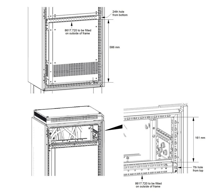
How to use this guide
This user guide provides complete information for installing the drive.
The information is in logical order, taking the reader from receiving the drive through to installation.
NOTE

There are specific safety warnings throughout this guide, located in the relevant sections. In addition, Chapter 1 Safety
information contains general safety information. It is essential that the warnings are observed and the information
considered when working with or designing a system using the drive.
This map of the user guide helps to find the right sections for the task you wish to complete, but for specific information,
refer to the table of contents overleaf.

                                                                                         Programming
                                 Quick Start /                                               and
                                                   Familiarisation    System design                        Troubleshooting
                                 bench testing                                          commissionaing

   1   Safety information

   2   Product information

   3   Mechanical installation

   4   Electrical installation

   5   Technical data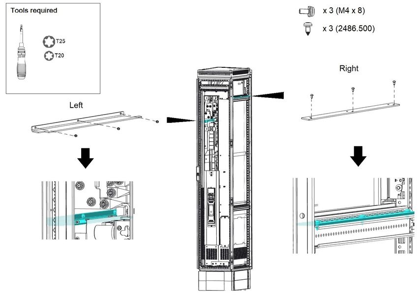
Contents
1      Safety information .................................6                          5     Technical data ..................................... 65
1.1    Warnings, Cautions and Notes .............................6                    5.1   Drive technical data ............................................ 65
1.2    General information ...............................................6           5.2   Optional external EMC filters ............................. 71
1.3    Responsibility ........................................................6
1.4    Compliance with regulations .................................6
1.5    Electrical hazards ..................................................6
1.6    Stored electrical charge ........................................6
1.7    Mechanical hazards ..............................................6
1.8    Access to equipment .............................................6
1.9    Environmental limits ..............................................6
1.10   Hazardous environments ......................................6
1.11   Motor .....................................................................7
1.12   Mechanical brake control ......................................7
1.13   Adjusting parameters ............................................7
1.14   Electromagnetic compatibility (EMC) ....................7

2      Product information ..............................8
2.1    Drive software version ...........................................8
2.2    Model number .......................................................8
2.3    Nameplate description ..........................................9
2.4    Ratings ................................................................10
2.5    Product features ..................................................12
2.6    Power module accessories .................................14

3      Mechanical installation .......................17
3.1    Safety information ...............................................17
3.2    Lifting the Power Module .....................................18
3.3    Planning the installation ......................................18
3.4    Input and output wiring kits .................................20
3.5    Tools required for installation ..............................21
3.6    Cubicle roof plate (VX25) ....................................22
3.7    Installation of power module into cubicle ............24
3.8    Terminal cover removal .......................................38
3.9    Dimensions .........................................................39
3.10   External EMC filter ..............................................40
3.11   Electrical terminals ..............................................42
3.12   Terminal sizes and torque settings .....................46
3.13   Routine maintenance ..........................................46
3.14   Replacement of serviceable parts .......................46

4      Electrical Installation ...........................47
4.1    Power connections ..............................................48
4.2    Output short circuit protection .............................48
4.3    Motor overload protection ...................................48
4.4    Use of a residual current device (RCD) ..............49
4.5    Supply requirements ...........................................50
4.6    Low voltage operation .........................................52
4.7    Ratings ................................................................53
4.8    Output circuit and motor protection .....................55
4.9    Braking ................................................................56
4.10   Ground leakage ...................................................58
4.11   EMC (Electromagnetic compatibility) ..................59

4                                                                                                           Power Module Frame 12 Installation Guide
EU Declaration of Conformity
1. Product model
Unidrive-M Variable Speed Motor Drives.
2. Name and address of the manufacturer
Nidec Control Techniques Ltd
The Gro
Newtown
Powys
SY16 3BE
UK

Registered in England and Wales. Company Reg. No. 01236886
Telephone: 00 44 1686 612300
E-mail: marketing.control techniques@mail.nidec.com
Web: www.controltechniques.com
3. This declaration is issued under the sole responsibility of the manufacturer.
4. Object of the declaration
     Model No.           Interpretation                                    Nomenclature aaaa - bbc ddddde
aaaa                   Basic series           M000 (configurable to M600, M700, M701, M702, F300, F600, H300)
bb                     Frame Size             12
c                      Voltage Rating         4 = 400 V, 5 = 575 V, 6 = 690 V
ddddd                  Current Rating         Example 01000 = 100 A
e                      Drive Format           D = Inverter, T = 12P Rectifier + Inverter (can be operated in 6 and 12 pulse)
The model number may be followed by additional characters that do not affect the ratings.
5. The object of the declaration is in conformity with the relevant European Union harmonisation legislation.
Restriction of Hazardous Substances Directive (2011/65/EU)
Low Voltage Directive (2014/35/EU)
Electromagnetic Compatibility Directive (2014/30/EU).
6. References to the relevant harmonised standards used
The variable speed drive products listed above have been designed and manufactured in accordance with the following European harmonised
standards:
                                              Adjustable speed electrical power drive systems - Part 5-1: Safety requirements - Electrical,
EN 61800-5-1:2007+ A1:2017
                                              thermal and energy
                                              Adjustable speed electrical power drive systems - Part 3: EMC requirements and specific test
EN 61800-3: 2018
                                              methods
                                              Electromagnetic compatibility (EMC) - Part 6-2: Generic standards - Immunity for industrial
EN 61000-6-2: 2005
                                              environments
                                              Electromagnetic compatibility (EMC) - Part 6-4: Generic standards - Emission standard for
EN 61000-6-4: 2007+ A1:2011
                                              industrial environments
                                              Electromagnetic compatibility (EMC) - Part 3-2: Limits for harmonic current emissions
EN 61000-3-2:2014
                                              (equipment input current ≤ 16 A per phase)
                                              Electromagnetic compatibility (EMC) - Part 3-3: Limitation of voltage changes, voltage
EN 61000-3-3:2013                             fluctuations and flicker in public, low voltage supply systems, for equipment with rated current
                                              ≤ 16 A per phase and not subject to conditional connection

EN 61000-3-2: 2014 Applicable where input current < 16 A. No limits apply for professional equipment where input power ≥ 1 kW.
7. Signed for and behalf of:
                               Jon Holman-White
                               Vice President of Research and Development
                               Nidec Control Techniques Ltd
                               Date: 27th June 2019
                               Newtown, Powys, UK.

These electronic drive products are intended to be used with appropriate motors, controllers, electrical protection components and other
equipment to form complete end products or systems. Compliance with safety and EMC regulations depends upon installing and
configuring drives correctly, including using the specified input filters.
The drives must be installed only by professional installers who are familiar with requirements for safety and EMC. Refer to the Product
Documentation. An EMC data sheet is available giving detailed information. The assembler is responsible for ensuring that the end product
or system complies with all the relevant laws in the country where it is to be used.

Power Module Frame 12 Installation Guide                                                                                                         5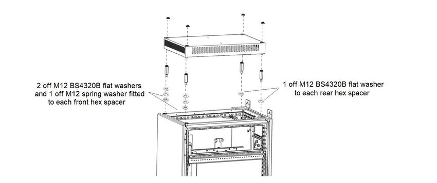
Safety information             Product information           Mechanical installation          Electrical Installation          Technical data

1             Safety information                                                 1.5          Electrical hazards
                                                                                 The voltages used in the drive can cause severe electrical shock and/or
1.1           Warnings, Cautions and Notes                                       burns and could be lethal. Extreme care is necessary at all times when
                                                                                 working with or adjacent to the drive. Hazardous voltage may be present
                                                                                 in any of the following locations:
              A Warning contains information which is essential for
                                                                                 •    AC and DC supply cables and connections
              avoiding a safety hazard.
                                                                                 •    Output cables and connections
    WARNING
                                                                                 •    Many internal parts of the drive, and external option units
                                                                                 Unless otherwise indicated, control terminals are single insulated and
                                                                                 must not be touched.
              A Caution contains information which is necessary for
              avoiding a risk of damage to the product or other equipment.       The supply must be disconnected by an approved electrical isolation
    CAUTION
                                                                                 device before gaining access to the electrical connections.
                                                                                 The STOP function of the drive does not isolate dangerous voltages
                                                                                 from the output of the drive or from any external option unit.
NOTE
A Note contains information which helps to ensure correct operation of           The drive must be installed in accordance with the instructions given in
the product.                                                                     this guide. Failure to observe the instructions could result in a fire
                                                                                 hazard.
1.2           General information
                                                                                 1.6          Stored electrical charge
This guide applies to products which control electric motors either
directly (drives) or indirectly (controllers, option modules and other           The drive contains capacitors that remain charged to a potentially lethal
auxiliary equipment and accessories). In all cases the hazards                   voltage after the AC supply has been disconnected. If the drive has been
associated with powerful electrical drives are present, and all safety           energized, the AC supply must be isolated at least ten minutes before
information relating to drives and associated equipment must be                  work may continue.
observed.
                                                                                 1.7          Mechanical hazards
Specific warnings are given at the relevant places in this guide.
                                                                                 Careful consideration must be given to the functions of the drive or
Drives and controllers are intended as components for professional
                                                                                 controller which might result in a hazard, either through their intended
incorporation into complete systems. If installed incorrectly they may
                                                                                 behaviour or through incorrect operation due to a fault. In any application
present a safety hazard. The drive uses high voltages and currents,
                                                                                 where a malfunction of the drive or its control system could lead to
carries a high level of stored electrical energy, and is used to control
                                                                                 or allow damage, loss or injury, a risk analysis must be carried out,
equipment which can cause injury. Close attention is required to the
                                                                                 and where necessary, further measures taken to reduce the risk -
electrical installation and the system design to avoid hazards either in
                                                                                 for example, an over-speed protection device in case of failure of the
normal operation or in the event of equipment malfunction. System
                                                                                 speed control, or a fail-safe mechanical brake in case of loss of motor
design, installation, commissioning/start-up and maintenance must be
                                                                                 braking.
carried out by personnel who have the necessary training and
competence. They must read this safety information and this guide                The system designer is responsible for ensuring that the complete
carefully.                                                                       system is safe and designed correctly according to the relevant safety
                                                                                 standards.
1.3           Responsibility                                                     The design of safety-related control systems must only be done by
It is the responsibility of the installer to ensure that the equipment is        personnel with the required training and experience. The system must
installed correctly with regard to all instructions given in this guide.         be subject to a risk assessment to confirm that the residual risk of an
They must give due consideration to the safety of the complete system,           unsafe event is at an acceptable level for the application.
so as to avoid the risk of injury both in normal operation and in the event
of a fault or of reasonably foreseeable misuse.                                  1.8          Access to equipment
The manufacturer accepts no liability for any consequences resulting             Access must be restricted to authorized personnel only. Safety
from inappropriate, negligent or incorrect installation of the equipment.        regulations which apply at the place of use must be complied with.

1.4           Compliance with regulations                                        1.9          Environmental limits
The installer is responsible for complying with all relevant regulations,        Instructions in this guide regarding transport, storage, installation and
such as national wiring regulations, accident prevention regulations and         use of the equipment must be complied with, including the specified
electromagnetic compatibility (EMC) regulations. Particular attention            environmental limits. This includes temperature, humidity,
must be given to the cross-sectional areas of conductors, the selection          contamination, shock and vibration. Drives must not be subjected to
of fuses or other protection, and protective ground (earth) connections.         excessive physical force.
This guide contains instructions for achieving compliance with specific
EMC standards.
                                                                                 1.10          Hazardous environments
                                                                                 The equipment must not be installed in a hazardous environment
All machinery to be supplied within the European Union in which this
                                                                                 (i.e. a potentially explosive environment).
product is used must comply with the following directives:
2006/42/EC Safety of machinery. 2014/30/EU: Electromagnetic
Compatibility.

6                                                                                                          Power Module Frame 12 Installation Guide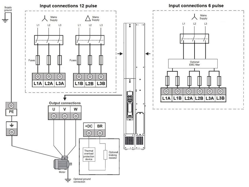
Safety information              Product information            Mechanical installation   Electrical Installation   Technical data

1.11        Motor
The safety of the motor under variable speed conditions must be
ensured.
To avoid the risk of physical injury, do not exceed the maximum specified
speed of the motor.
Low speeds may cause the motor to overheat because the cooling fan
becomes less effective, causing a fire hazard. The motor should be
installed with a protection thermistor. If necessary, an electric forced vent
fan should be used.
The values of the motor parameters set in the drive affect the protection
of the motor. The default values in the drive must not be relied upon. It is
essential that the correct value is entered in the Motor Rated Current
parameter.

1.12         Mechanical brake control
Any brake control functions are provided to allow well co-ordinated
operation of an external brake with the drive. While both hardware and
software are designed to high standards of quality and robustness, they
are not intended for use as safety functions, i.e. where a fault or failure
would result in a risk of injury. In any application where the incorrect
operation of the brake release mechanism could result in injury,
independent protection devices of proven integrity must also be
incorporated.

1.13         Adjusting parameters
Some parameters have a profound effect on the operation of the drive.
They must not be altered without careful consideration of the impact on
the controlled system. Measures must be taken to prevent unwanted
changes due to error or tampering.

1.14         Electromagnetic compatibility (EMC)
Installation instructions for a range of EMC environments are provided
in the relevant Power Installation Guide. If the installation is poorly
designed or other equipment does not comply with suitable standards
for EMC, the product might cause or suffer from disturbance due to
electromagnetic interaction with other equipment. It is the responsibility
of the installer to ensure that the equipment or system into which the
product is incorporated complies with the relevant EMC legislation in the
place of use.

Power Module Frame 12 Installation Guide                                                                                                  7
Safety information                          Product information             Mechanical installation         Electrical Installation                 Technical data

2               Product information
This guide provides the information necessary to install and commission the Power Module Frame 12.
The power module is intended to be installed into the cubicle by the system integrator using the standard engineering accessories (SEA’s). The SEA's
are listed in Table 2-6 on page 14.
The power module is constructed from a kit of the following sub-assemblies which can be ordered individually. See Table 2-8 on page 15.
•      Inverter
•      Rectifier
•      Power Control PCB
•      SMPS assembly
•      Fan assembly

2.1             Drive software version
This product is supplied with the latest software version. If this drive is to be connected to an existing system or machine, all drive software versions
should be verified to confirm the same functionality as drives of the same model already present. This may also apply to drives returned from a
Control Techniques Service Centre or Repair Centre. If there is any doubt, please contact the supplier of the product. The software version of the
drive can be checked by looking at Pr 11.029 and Pr 11.034. This takes the form of xx.yy.zz where Pr 11.29 displays xx.yy and Pr 11.34 displays zz.
(e.g. for software version 01.01.00, Pr 11.029 = 1.01 and Pr 11.034 displays 0).

2.2             Model number
The way in which the model numbers for the Unidrive M/ Pump drive range are formed is illustrated below.

Figure 2-1            Model numbers

                          Identification Label
         Derivative          Electrical Specifications        Power    Configuration                Documentation Customer Code             Optional Build
                                                                                        Reserved
                                                              Format

        M600 -              12        4       07200             T            1              0             1           01            A      B      1     0       0

    Product Line                                                                                                                                             Reserved:
    Unidrive M600
    Unidrive M700
    Unidrive M701                                                                                                                                            Conformal Coating:
    Unidrive M702                                                                                                                                            0 = Standard
    Powerdrive F300
    Pump Drive F600                                                                                                                                          IP / NEMA Rating:
    HVAC drive H300
                                                                                                                                                             1 = IP 00/ NEMA (Open type)

    Frame Size:                                                                                                                                              Brake Transistor:
                                                                                                                                                             B = Brake
    Voltage Rating:
    4 - 400 V (380 - 480 ± 10 %)
    5 - 575 V (500 - 675 ± 10 %)                                                                                                                             Cooling:
    6 - 690 V (500 - 690 ± 10 %)                                                                                                                             A = Air
    Current Rating:
    Heavy Duty current rating x 10
                                                                                                                                                             Customer Code:
                                                                                                                                                             00 = 50 Hz
                                                                                                                                                             01 = 60 Hz
    Power Format:
    T - AC in AC out (6/12P rectifier plus inverter)
                                                                                                                                                               Documentation:
    D - DC in AC out (Inverter only)                                                                                                                           1 - English

    Configuration:
    1 - Standard
    U - No Control

8                                                                                                                            Power Module Frame 12 Installation Guide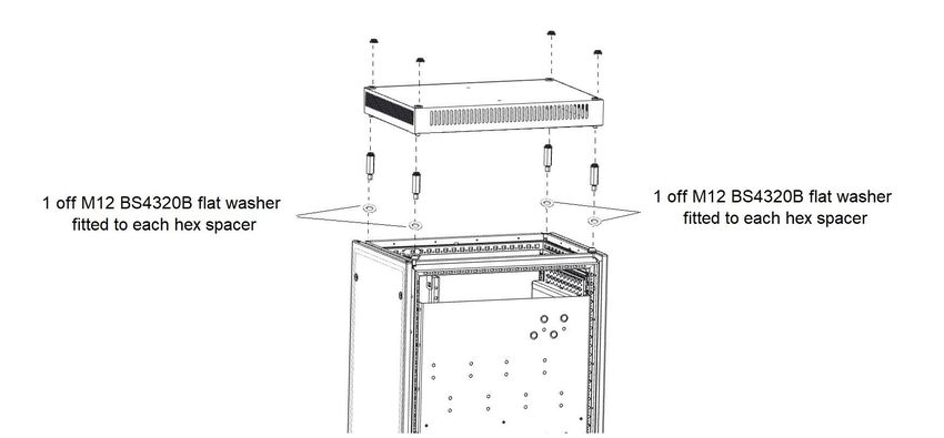
Safety information          Product information          Mechanical installation           Electrical Installation             Technical data

2.3        Nameplate description
Figure 2-2     Typical drive rating labels

                            Key to approvals

                                 CE approval                    Europe

                              WEEE Approved                     Europe

                                                                                          NOTE
                                 China RoHS                      China
                                                                                      Conformity approvals on labels are variable
                                                                                      and subject to change to include others from
                                                                                      within this list.
                               UKCA approval                       UK
                                                                                      See current label on physical product for up to
                                                                                      date approvals.
                         Regulatory Compliance Mark
                                                              Australia
                                    (RCM)

                            Eurasian conformity                 Eurasia

                             Korean conformity                   Korea

                                                           Input frequency

         Approvals                                                                                                     Date code

                                   M000-124 05660 TU0           315/355 kW                 2020
         Input voltage               I/P 380-480V 50-60Hz     2x3ph                        777A                             Input phases & input current
       Output voltage                0/P 0-480V    0-599Hz     3ph                     566/660A                             Output phases & Heavy
                                     S/N: 300005001      IP20                         IE2.VSD 98%                           Duty /Normal Duty rating

         Serial number               Control Techniques, The Gro, Newtown, Powys,
                                     United Kingdom, SY16 3BE
                                     Made in U.K.                    Patents: www.ctpatents.info
                                                                     Manuals: www.ctmanuals.info

NOTE
Date code format
The date code is four numbers. The first two numbers indicate the year and the remaining numbers indicate the week of the year in which the drive
was built.
Example:
A date code of 1910 would correspond to week 10 of year 2019.

Power Module Frame 12 Installation Guide                                                                                                                   9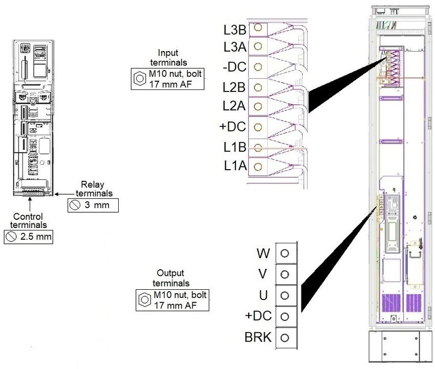
Safety information            Product information             Mechanical installation          Electrical Installation              Technical data

2.4          Ratings
The continuous current ratings given are for maximum 40 °C (104 °F),1000 m altitude and 2 kHz switching frequency. Derating is required for higher switching
frequencies, higher ambient temperatures and high altitude. For further information, refer to section 5 Technical data, Power and current ratings (Derating for
switching frequency and temperature).

NOTE
With regard to Table 2-1 to Table 2-4, derating is applied to all drives at low output frequencies. Please contact the supplier of the drive for more
information if the application requires significant torque, at or close to zero speed for extended periods of time or if prolonged periods of overload
(> 100 %) are required.

Table 2-1      400 V drive ratings at 40 °C (104 °F) 12 pulse (380 V to 480 V ±10 %)
                              No overload                                   Normal Duty                                           Heavy Duty

                                                                                                               Maximum
                 Maximum        Nominal      Nominal        Maximum                  Nominal    Nominal                                   Nominal     Nominal
                                                                       Peak                                   continuous         Peak
     Model      continuous      power at     power at      continuous                power at   power at                                  power at    power at
                                                                      current                                   output          current
                  current        400 V        460 V          current                  400 V      460 V                                     400 V       460 V
                                                                                                                current

                      A            kW            hp             A            A          kW         hp               A             A         kW              hp

 12404800T           635          315           500            608          668         315        500             480           672        250             400
 12405660T           689          355           550            660          726         355        550             566           792        315             450
 12406600T           788          450           650            755          831         400        650             660           924        355             550
 12407200T           903          500           700            865          952         500        700             720           1008       400             600

Table 2-2      575 V drive ratings at 40 °C (104 °F) 12 pulse (500 V to 575 V ±10 %)
                              No overload                                   Normal Duty                                           Heavy Duty

                                                                                                               Maximum
                 Maximum        Nominal      Nominal        Maximum                  Nominal    Nominal                                   Nominal     Nominal
                                                                       Peak                                   continuous         Peak
     Model      continuous      power at     power at      continuous                power at   power at                                  power at    power at
                                                                      current                                   output          current
                  current        575 V        575 V          current                  575 V      575 V                                     575 V       575 V
                                                                                                                current

                      A            kW            hp             A            A          kW         hp               A             A         kW              hp

 12503150T           375          250           350            360          396         250        350             315           441        250             350
 12503600T           426          300           400            410          451         300        400             360           504        250             350
 12504100T           479          330           450            460          506         330        450             410           574        300             400
 12504600T           530          370           500            510          561         370        500             460           644        330             450

Table 2-3      690 V drive ratings at 40 °C (104 °F) 12 pulse (500 V to 690 V ±10 %)
                              No overload                                   Normal Duty                                           Heavy Duty

                                                                                                               Maximum
                 Maximum        Nominal      Nominal        Maximum                  Nominal    Nominal                                   Nominal     Nominal
                                                                       Peak                                   continuous         Peak
     Model      continuous      power at     power at      continuous                power at   power at                                  power at    power at
                                                                      current                                   output          current
                  current        690 V        690 V          current                  690 V      690 V                                     690 V       690 V
                                                                                                                current

                      A            kW            hp             A            A          kW         hp               A             A         kW              hp

 12603150T           375          355           450            360          396         355        450             315           441        280             400
 12603600T           426          400           500            410          451         400        500             360           504        355             450
 12604100T           479          450           600            460          506         450        600             410           574        400             500
 12604600T           530          500           650            510          561         500        650             460           644        450             600

NOTE
No overload is with zero overload. ND includes 10 % overload and HD includes 140 % overload.

10                                                                                                          Power Module Frame 12 Installation Guide
Safety information Product information Mechanical installation Electrical Installation Technical data
2.4.1 Typical short-term overload limits
The maximum percentage overload limit changes depending on the selected motor. Variations in motor rated current, motor power factor and motor
leakage inductance all result in changes in the maximum possible overload.
Typical values are shown in the table below for RFC and open loop (OL) modes:
Table 2-4 Typical overload limits
Operating mode RFC from cold RFC from 100 % Open loop from cold Open loop from 100 %
Normal Duty overload with motor rated current =
110 % for 180 s 110 % for 10 s* 110 % for 180 s 110 % for 10 s*
drive rated current
Heavy Duty overload with motor rated current =
140 % for 60 s 140 % for 10 s 140 % for 60 s 140 % for 10 s
drive rated current
* 1240720T rating provides 110 % for 3 s from rated normal duty current. 110 % is available for 10 s when limited to 850 A continuous.
12406600T and 12405660T support 110 % for 10 s.
Generally, the drive rated current is higher than the matching motor rated current allowing a higher level of overload than the default setting. The time
allowed in the overload region is proportionally reduced at very low output frequency on some drive ratings.
NOTE
The maximum overload level which can be attained is independent of the speed.
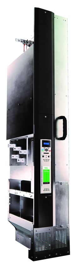
Power Module Frame 12 Installation Guide 11Safety information Product information Mechanical installation Electrical Installation Technical data 2.5 Product features The power module is to be installed into a cubicle. It can be transported using the lifting trolley or can be wheeled using the castors. Figure 2-3 Features of the power module (with control pod fitted) 12 Power Module Frame 12 Installation Guide
Safety information          Product information           Mechanical installation        Electrical Installation          Technical data

NOTE
The power module is supplied without a control pod. The drive derivative, e.g. M700, is achieved by fitting the appropriate control pod.

Figure 2-4     Features of the drive cubicle (with control pod fitted)

Power Module Frame 12 Installation Guide                                                                                                          13
Safety information            Product information                  Mechanical installation          Electrical Installation             Technical data

2.6         Power module accessories
The following items in Table 2-5 will be provided with the control pod. The part number of the kit box is 3470-0082.

Table 2-5       Parts supplied with the control pod
   Part                                                     Part                         Part                                                     Part
                             Description                                 Quantity                                Description                                 Quantity
  number                                                  supplied                      number                                                  supplied

 6541-0110              EMC frame (control)                                  1         3438-2011     11-way terminal block (marked 1-11)                         1

 3438-3813              13-way terminal plug                                 1         3438-3011     11-way terminal block (marked 21-31)                        1

                                                                                                             2-way terminal block
 3438-2002          2-way terminal plug (relay)                              1         3438-4202                                                                 1
                                                                                                               (24 Vdc back-up)

2.6.1        Standard Engineering Accessories
To facilitate the installation of the power module into a cubicle, one, or more of the following kits are required.

Table 2-6       Standard Engineering Accessories
             Part number                               Description                                                      Availability

             6772-0006-01                      VX25/TS8 input wiring kit                                    Available from Control Techniques
             6772-0007-01                      VX25/TS8 output wiring kit                                   Available from Control Techniques
             6772-0008-01                           VX25/TS8 earth kit                                      Available from Control Techniques
             6772-0014-00                  Output busbar pass-through kit                                   Available from Control Techniques
             6772-0016-00                         DC only input wiring kit                                  Available from Control Techniques
             6772-0012-00                          DC input busbar kit                                      Available from Control Techniques
             6772-0009-01                             VX25 fitting kit                                      Available from Control Techniques
                  N/A                                  TS8 fitting kit                          To be sourced locally. Drawings available on Support Suite
             4200-6326-00                                AFE filter                                         Available from Control Techniques
             6772-0015-00                          VX25 AFE fitting kit                                     Available from Control Techniques
                  N/A                                   TS8 ramp                                To be sourced locally. Drawings available on Support Suite
             6500-0158-00                               VX25 ramp                                           Available from Control Techniques
             6500-0159-00                           VX25/TS8 lifting kit                                    Available from Control Techniques
            GTBU580F-07                         External brake chopper                                              Available from NIS
               9681.846                              VX25 roof plate                                               Available from Rittal
               4595.000                                Wall bracket                                                Available from Rittal
               3423.200                        TS8 Outlet filter with mat                                          Available from Rittal
               3420.200                    VX 25 Outlet filter with filter mat                                     Available from Rittal

NOTE
To ensure that installation accessories are available together, Table 2-6 must be considered and the required parts ordered when raising an order for
the Power Module Frame 12.
NOTE
The following instructions are available on line. Some of these require additional components to be ordered, details of which are in the respective
instruction.
VX25/TS8 fitting kit
VX25/TS8 Output pass-through busbar kit
VX25/TS8 lifting kit

14                                                                                                                Power Module Frame 12 Installation Guide
Safety information Product information Mechanical installation Electrical Installation Technical data
2.6.2 Power module and sub assembly part numbers
Table 2-7 Power module part numbers
Voltage rating Part number Description
M000-12404800TU0100AB100 12404800T
M000-12405660TU0100AB100 12405660T
400 V
M000-12406600TU0100AB100 12406600T
M000-12407200TU0100AB100 12407200T
M000-12503150TU0100AB100 12503150T
M000-12503600TU0100AB100 12503600T
575 V
M000-12504100TU0100AB100 12504100T
M000-12504600TU0100AB100 12504600T
M000-12603150TU0100AB100 12603150T
M000-12603600TU0100AB100 12603600T
690 V
M000-12604100TU0100AB100 12604100T
M000-12604600TU0100AB100 12604600T
Table 2-8 Sub assembly part numbers
Voltage rating Part number Description
M000-12XSMPS000000000000 400 V SMPS
All
M000-12XFANBOX0000000000 Fan Assembly
M000-124INVERTER00000000 400 V Inverter
400 V M000-124RECTIFIER0000000 400 V Rectifier
M000-124INVCONTROL000000 UF25K Power control PCB
M000-125INVERTER00000000 575 V Inverter
575 V M000-125RECTIFIER0000000 575 V Rectifier
M000-125INVCONTROL000000 UF25K Power control PCB
M000-126INVERTER00000000 690 V Inverter
690 V M000-126RECTIFIER0000000 690 V Rectifier
M000-126INVCONTROL000000 UF25K Power control PCB
2.6.3 Lifting kit
To aid the installation of the power module into the cubicle there are two types of accessory.
1. Lifting kit - This includes a transport cradle for transporting the power module using a pallet truck. Part number 6500-0159.
Figure 2-5 Lifting kit
Power Module Frame 12 Installation Guide 15Safety information Product information Mechanical installation Electrical Installation Technical data 2. VX25 Ramp - The ramp attaches directly to the cubicle allowing the power module to be pushed into the cubicle. Part number 6500-0158 Figure 2-6 VX25 ramp 16 Power Module Frame 12 Installation Guide
Safety information              Product information           Mechanical installation         Electrical Installation         Technical data

3           Mechanical installation
This chapter describes how to use all mechanical details to install the power module. Key features of this chapter include cubicle installation, terminal
location and torque settings.

3.1         Safety information
             Follow the instructions                                                           Isolation device
             The mechanical and electrical installation instructions must                      The AC supply must be disconnected from the drive using an
             be adhered to. Any questions or doubt should be referred to                       approved isolation device before any cover is removed from
             the supplier of the equipment. It is the responsibility of the        WARNING     the drive or before any servicing work is performed.
 WARNING     owner or user to ensure that the installation of the drive and
             any external option unit, and the way in which they are
             operated and maintained, comply with the requirements of
             the Health and Safety at Work Act in the United Kingdom or
             applicable legislation and regulations and codes of practice                      The weight of the product is: 130 kg (287 lb)
             in the country in which the equipment is used.
                                                                                    CAUTION

             Hazardous areas
             The drive must not be installed in a classified hazardous
             area unless it is installed in an approved enclosure and the
  WARNING
             installation is certified.

             Stored charge
             The drive contains capacitors that remain charged to a
             potentially lethal voltage after the AC supply has been
             disconnected. If the drive has been energized, the AC supply
 WARNING
             must be isolated for at least ten minutes before work may
             continue.
             Normally, the capacitors are discharged by an internal
             resistor. Under certain, unusual fault conditions, it is possible
             that the capacitors may fail to discharge or be prevented
             from being discharged by a voltage applied to the output
             terminals. If the drive has failed in a manner that causes the
             display to go blank immediately, it is possible the capacitors
             will not be discharged. In this case, consult Control
             Techniques or their authorized distributor.

             Protection of equipment prior to installation
             If the equipment is not to be installed immediately, it must be
             protected from moisture and dust. It is recommended that
             the equipment remains in its packaging prior to installation to
  CAUTION    protect it from mechanical damage, moisture and dust.

Power Module Frame 12 Installation Guide                                                                                                              17
Safety information Product information Mechanical installation Electrical Installation Technical data
3.2 Lifting the Power Module 3.3.5 Fire protection
The drive enclosure is not classified as a fire enclosure. A separate fire
enclosure must be provided.
Lifting and handling
Always lift the drive by the lifting points. Care must be taken For installation in the USA, a NEMA 12 enclosure is suitable.
when lifting as the Power Module could overbalance if not For installation outside the USA, the following (based on IEC 62109-1,
WARNING lifted correctly. Wear safety shoes. standard for PV inverters) is recommended.
Enclosure can be metal and/or polymeric, polymer must meet
When removing the Power Module from the packaging, connect bow requirements which can be summarized for larger enclosures as using
shackles rated to 500 kg (1102 lbs) to the two lifting points, which materials meeting at least UL 94 class 5VB at the point of minimum
measure 17.5 mm diameter, shown in Figure 3-1, and slowly raise into a thickness.
vertical position.
Air filter assemblies to be at least class V-2.
Figure 3-1 Lifting the Power Module The location and size of the bottom shall cover the area shown in
Figure 3-2. Any part of the side which is within the area traced out by the
5° angle is also considered to be part of the bottom of the fire enclosure.
Lifting points Figure 3-2 Fire enclosure bottom layout
Drive
o
5
o
5
3.3 Planning the installation
The following considerations must be made when planning the
installation:
The bottom, including the part of the side considered to be part of the
3.3.1 Access bottom, must be designed to prevent escape of burning material - either
Access must be restricted to authorized personnel only. by having no openings or by having a baffle construction. This means
Safety regulations which apply at the place of use must be complied that openings for cables etc. must be sealed with materials meeting the
with. 5VB requirement, or else have a baffle above.
See Figure 3-3 for acceptable baffle construction. This does not apply
3.3.2 Environmental protection for mounting in an enclosed electrical operating area (restricted access)
The drive must be protected from: with concrete floor.
• Moisture, including dripping water or spraying water and
Figure 3-3 Fire enclosure baffle construction
condensation.
Not less
• Contamination with electrically conductive material than 2
• Contamination with any form of dust which may restrict the fan, or times ‘X’
N o t le s s
th a n 2 X
Baffle plates (may be above or
B a f f le p la t e s ( m a y b e
below bottom of enclosure)
a b o v e o r b e lo w b o t t o m
impair airflow over various components o f e n c lo s u r e )
• Temperature beyond the specified operating and storage ranges XX
• Corrosive gasses B o t t o m o f f ir e
Bottom of fire enclosure
e n c lo s u r e
3.3.3 Cooling
The inlet and outlet vents on the drive must not be restricted or covered.
3.3.6 Electromagnetic compatibility
The ambient temperature must not exceed the specified operating Variable speed drives are powerful electronic circuits which can cause
temperature of the drive. electromagnetic interference if not installed correctly with careful
attention to the layout of the wiring.
3.3.4 Electrical safety
Some simple routine precautions can prevent disturbance to typical
The installation must be safe under normal and fault conditions. industrial control equipment.
Electrical installation instructions are given in Chapter 4 Electrical
If it is necessary to meet strict emission limits, or if it is known that
Installation on page 47.
electromagnetically sensitive equipment is located nearby, then full
precautions must be observed. In-built into the drive, is an internal
EMC filter, which reduces emissions under certain conditions. If these
conditions are exceeded, then the use of an external EMC filter may be
required at the drive inputs, which must be located as close to the drive
as possible.
18 Power Module Frame 12 Installation GuideSafety information Product information Mechanical installation Electrical Installation Technical data
3.3.7 Hazardous areas
The drive must not be located in a classified hazardous area.
Hot surfaces
Care must be taken when opening the cubicle door as some
components may be hot to the touch even after the
WARNING
10 minutes discharge time.
Component IP ratings
The Power Module is rated to IP00. This must be taken into
consideration when the cubicle doors are open.
WARNING
Power Module Frame 12 Installation Guide 19Safety information Product information Mechanical installation Electrical Installation Technical data
3.4 Input and output wiring kits
The input and output wiring kits and earthing plate kit are supplied as separate parts.
Figure 3-4 Input, output wiring kit and earthing plate kits
Input wiring kit
Earthing plate kit (6772-0006-00)
(6772-0008-00)
Output wiring kit
(6772-0007-00)
NOTE
The input wiring kit is supplied without +/- DC terminals. If these are required they must be ordered separately and fitted to the wiring kit prior to
installation. See Table 2-6 for more information.
Figure 3-5 Output busbar pass through kit
An output busbar pass through kit is available (See Table 2-6 for details) which allows the motor cables to be connected from the incomer cubicle as
oppose to the drive cubicle. This kit is intended to improve cable routing and simplify installation.
An installation guide detailing parts required and fitting instructions is available on Support Suite and the CT website.
20 Power Module Frame 12 Installation GuideSafety information Product information Mechanical installation Electrical Installation Technical data
3.5 Tools required for installation
The tools required for installing the power module into the cubicle are
shown in Figure 3-6.
Figure 3-6 Tools required for installation
Torque wrench Socket size
17 mm 13 mm 10 mm
Socket extension bar Length
500 mm
Torque driver Torx bit size
3.5.1 Torx driver sizes by fastener
Table 3-1 Torx driver bit sizes by fastener
Description Torx driver size
M5 x 12 double SEM torx screw T25
M6 x 16 double SEM torx screw T30
M6 x 20 double SEM torx screw T30
M8 x 16 double SEM torx screw T40
Multi-tooth screw 5.5 x 13 mm (Rittal screw) T25
Power Module Frame 12 Installation Guide 21Safety information Product information Mechanical installation Electrical Installation Technical data 3.6 Cubicle roof plate (VX25) 3.6.1 Stand-alone applications To allow sufficient air flow, the VX25 roof plate (9681.846) must be fitted to the top of the cubicle. For stand-alone applications where attaching the cubicle to a fixed surface is not required the roof plate can be fitted as supplied. Remove the standard top plate and fit the roof plate fittings as shown in Figure 3-7. Tighten 4 off M12 hex spacers to 20 Nm (177 lb in). NOTE The VX25 roof plate is rated to IP21 Figure 3-7 Fitting the VX25 roof plate 3.6.2 Fastening the cubicle to a fixed surface It may be a requirement to fasten the cubicle to a fixed surface for applications where shock and vibration may be present. This requires a modification of the VX25 roof plate to allow the Rittal wall brackets (4595.000) to be fitted. Figure 3-8 shows a modified VX25 roof plate. Figure 3-8 Modification details of VX25 roof plate to allow fitting of wall brackets 22 Power Module Frame 12 Installation Guide
Safety information           Product information         Mechanical installation         Electrical Installation           Technical data

3.6.3        Fitting wall brackets to fixed surface
With the cubicle in the desired position mark the holes, drill the holes and fasten the wall brackets to the fixed surface as shown in Figure 3-9

Figure 3-9      Fitting the wall brackets

3.6.4        Fit washers as shown in Figure 3-12
Fit 6 off M12 BS4320B flat washers and 2 off M12 spring washers as shown in Figure 3-12. Tighten 4 off M12 hex spacers to 60 Nm (531 lb in).

Figure 3-10 Preparing to fit the roof plate

Power Module Frame 12 Installation Guide                                                                                                            23
Safety information         Product information         Mechanical installation        Electrical Installation         Technical data

3.7        Installation of power module into cubicle
The following steps should be followed when installing a power module into a cubicle. The required parts are available as part of the power module
installation kit.
3.7.1        Fit braces to the cubicle for support
Figure 3-11 Fit the support braces to the upper and lower ends of the right side of the cubicle

24                                                                                                  Power Module Frame 12 Installation Guide
Safety information Product information Mechanical installation Electrical Installation Technical data
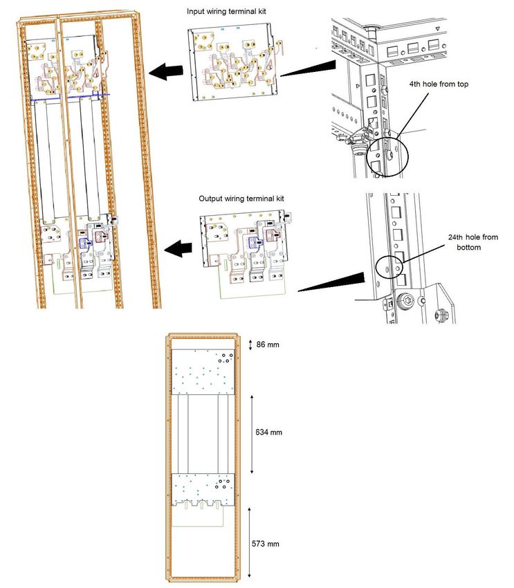
3.7.2 Install input and output wiring terminal kits to the cubicle as defined in the specified dimensions
below.
Figure 3-12 Installation of input and output wiring kits
Power Module Frame 12 Installation Guide 25Safety information Product information Mechanical installation Electrical Installation Technical data
3.7.3 Install earthing plates between the wiring kits. Fasten using 8 off M6 nuts and tighten to 6 Nm (531 lb
in).
Figure 3-13 Installation of earthing plates
26 Power Module Frame 12 Installation GuideSafety information Product information Mechanical installation Electrical Installation Technical data 3.7.4 Connect input, output and earth cables to wiring terminal kits. NOTE To aid cable installation, the input phase busbars are supplied loose on the input wiring kit. • Position L3B busbar to the position furthest back on the wiring plate • Tighten 2 off M8 screws to 12 Nm (53.1 lb in) • Attach the L3B supply cables using suitably sized ring tongue terminals with M10 nuts • Tighten the M10 nuts to 30 Nm (265.5 lb in) • Repeat for each input busbar in turn in order L3A, *(DC-), L2B, L2A, *(DC+), L1B, L1A. * If the DC +/- busbars are required then the above process should be followed. Figure 3-14 Connection of input output and ground cables NOTE Wiring configurations marked on terminal kit busbars to aid installation. NOTE Selected roof, glands and associated parts to be fitted at this stage. Power Module Frame 12 Installation Guide 27
Safety information Product information Mechanical installation Electrical Installation Technical data
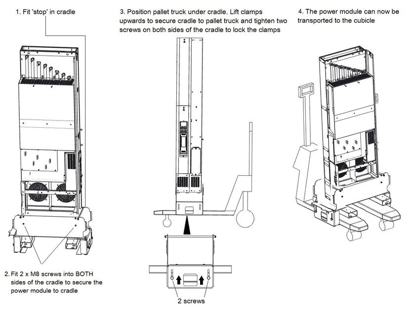
3.7.5 If the power module requires transporting to the cubicle, fit the power module into the cradle. If the
power module does not require transportation the ramp can be connected directly to the cubicle.
See section 3.7.9 for details.
Figure 3-15 Mounting the drive on the pallet truck lifting kit
Push power module slowly up the ramp. Ensure that it is held firmly at all times. The use of gloves is recommended.
WARNING
Wear safety shoes when transporting the power module.
WARNING
28 Power Module Frame 12 Installation GuideSafety information Product information Mechanical installation Electrical Installation Technical data
3.7.6 Wheel the power module into the cubicle, ensuring alignment of all busbar threaded connections
during the final part of movement.
Figure 3-16 Transporting the power module on the pallet truck lifting kit
NOTE
The pallet truck forks are intended to fit underneath the fork supports as shown in part 4 of Figure 3-16.
Check that ‘stop’ is firmly located at both ends. Failure to correctly fit the ‘stop’ could cause the power module to fall from the cradle.
WARNING
Ensure that the screws are fitted through the cradle into the power module on both sides and the screws are fitted to the cradle to lock it
against the pallet truck forks.
WARNING
Power Module Frame 12 Installation Guide 29Safety information Product information Mechanical installation Electrical Installation Technical data 3.7.7 Attach the bridge between the cradle and the cubicle. Figure 3-17 Bridge attachment and removal of stop 30 Power Module Frame 12 Installation Guide
Safety information           Product information         Mechanical installation    Electrical Installation   Technical data

3.7.8        Fit the power module into the cubicle. Ensure terminal busbar alignment is correct.
Figure 3-18 Installing the power module into the cubicle

             Keep fingers clear of front of cubicle when sliding power module.

 WARNING

             Ensure correct alignment of busbars when locating power module to prevent damage to threads.

 CAUTION

Power Module Frame 12 Installation Guide                                                                                               31
Safety information Product information Mechanical installation Electrical Installation Technical data
3.7.9 Installing the cubicle using the ramp only. Ensure terminal busbar alignment is correct.
Figure 3-19 Using the ramp to install the power module
Push power module slowly up the ramp. Ensure that it is held firmly at all times. The use of gloves is recommended.
WARNING
Wear safety shoes when transporting the power module.
WARNING
Keep fingers clear of front of cubicle when sliding power module.
WARNING
Ensure correct alignment of busbars when locating power module to prevent damage to threads.
CAUTION
32 Power Module Frame 12 Installation GuideSafety information Product information Mechanical installation Electrical Installation Technical data
3.7.10 Fit 15 x M10 nuts to the main input and output power terminals and ground connections.
See section 3.11.5 for location of ground connections.
Tighten loosely to ensure that alignment of terminals is achieved.
Figure 3-20 Fitting the nuts to the power terminals
Care must be taken to prevent the fasteners from falling into the cubicle.
CAUTION
Power Module Frame 12 Installation Guide 33Safety information Product information Mechanical installation Electrical Installation Technical data
3.7.11 With the power module in the cubicle, fit M8 nut over ground stud and tighten to 2 Nm (17.7 lb in). This
connects the chassis of the power module to ground.
Figure 3-21 Grounding the power module to the cubicle
34 Power Module Frame 12 Installation GuideSafety information Product information Mechanical installation Electrical Installation Technical data
3.7.12 Install recirculation baffles to upper right and upper left sides. Insert 3 off M4 x 8 screws into left baffle
and tighten to 2 Nm (17.7 lb in). Insert 3 of Rittal multi-tooth 2486.500 screws in right baffle and tighten
to 6 Nm (53.1 lb in).
Figure 3-22 Installation of recirculation baffles
Care must be taken to prevent the fasteners from falling into the cubicle.
CAUTION
Power Module Frame 12 Installation Guide 35Safety information Product information Mechanical installation Electrical Installation Technical data 3.7.13 Attach control pod terminal cover and gland plate. Tighten M4 x 12 screw to 2 Nm (17.7 lb in). Figure 3-23 Attaching control pod terminal cover and gland plate 36 Power Module Frame 12 Installation Guide
Safety information Product information Mechanical installation Electrical Installation Technical data
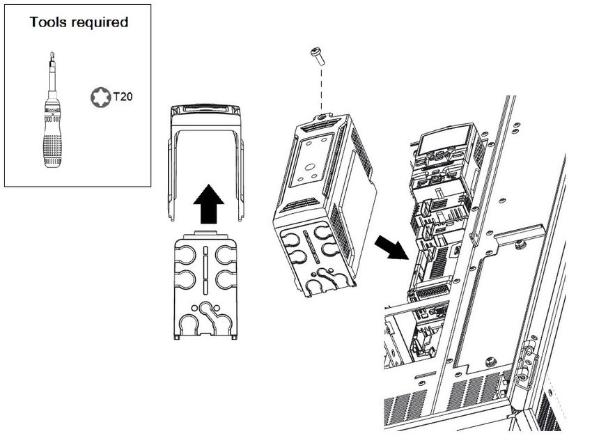
3.7.14 Attach terminal covers and fit 2 off M5 x 12 screws. Tighten to 4 Nm (35.4 lb in). Insert the control pod
panel and fit one M4 x 8 screw. Tighten to 2 Nm (17.7 lb in).
Figure 3-24 Attach terminal covers
Power Module Frame 12 Installation Guide 37Safety information Product information Mechanical installation Electrical Installation Technical data
3.8 Terminal cover removal
Isolation of the cubicle
The AC supply must be disconnected from the drive using the supply isolator before any cover is removed from the drive or before any
servicing work is performed.
WARNING
Stored charge
The drive contains capacitors that remain charged to a potentially lethal voltage after the AC supply has been disconnected. If the drive
has been energized, the AC supply must be isolated at least ten minutes before work may commence.
Normally, the capacitors are discharged by an internal resistor. Under certain, unusual fault conditions, it is possible that the capacitors
WARNING
may fail to discharge or be prevented from being discharged by a voltage applied to the output terminals. If the drive has failed in a manner
that causes the display to go blank immediately, it is possible the capacitors will not be discharged. In this case, consult Control Techniques
or their authorized distributor.
3.8.1 Removing the drive control terminal covers
The power module control terminals are fitted with terminal covers. The terminal covers must be removed to gain access to the control terminals.
NOTE
Refer to the relevant control user guide for details on the control terminal layout, functionality and option modules.
Figure 3-25 Location and identification of terminal covers for power module
38 Power Module Frame 12 Installation GuideSafety information Product information Mechanical installation Electrical Installation Technical data 3.9 Dimensions Figure 3-26 Power Module dimensions (shown in mm) Power Module Frame 12 Installation Guide 39
Safety information            Product information               Mechanical installation   Electrical Installation             Technical data

3.10       External EMC filter
To provide customers with a degree of flexibility, external EMC filters have been sourced from two manufacturers: Schaffner and Block. Filter details
for each drive rating are provided in the tables below.

NOTE
If an external EMC filter is to be installed, it must be installed in an incomer cabinet.

Table 3-2       External EMC filter details
                                                            Schaffner                                                       Block
             Drive
                                       Part number                            Weight                Part number                         Weight

400 V
          12404800T
          12405660T
                                FN 3311-1000-99-C16-R55                   5.5 kg (12.1 lb)        HLD 103-500/1000                  22.5 kg (49.6 lb)
          12406600T
          12407200T
575 V
          12503150T
          12503600T
                               FN3311HV-1000-99-C18-R55                   6.1 kg (13.4 lb)        NO 690 V OFFER                    NO 690 V OFFER
          12504100T
          12504600T
690 V
          12603150T
          12603600T
                               FN3311HV-1000-99-C18-R55                   6.1 kg (13.4 lb)        NO 690 V OFFER                    NO 690 V OFFER
          12604100T
          12604600T

Figure 3-27 Schaffner external EMC filter

40                                                                                                      Power Module Frame 12 Installation Guide
Safety information Product information Mechanical installation Electrical Installation Technical data
Table 3-3 Schaffner External EMC filter dimensions
Drive
Part number voltage A B C D E F1 F2 G H J K L O P U V W X Y Z
rating
FN 3311-1000-99-
400 V 190 220 140 305 220 180 185 Ø9 2.5 M8 225 ±1 245 30 59 ±0.5 53 40 8 20 58 Ø 13.5
C16-R55
FN3311HV-1000-99-
575 / 690 V 190 290 140 305 220 250 255 Ø9 2.5 M8 225 ±1 245 29.5 59 ±0.5 53 40 8 20 57.5 Ø 13.5
C18-R55
Figure 3-28 Block external EMC filter
Table 3-4 Block external EMC filter dimensions
Part number A B C D E F G H I J K L M N Q
HLD 103-500/1000 460 280 130 350 230 255 145 60 8 M8 40 55 20 20 Ø 14
Power Module Frame 12 Installation Guide 41Safety information Product information Mechanical installation Electrical Installation Technical data 3.11 Electrical terminals 3.11.1 Power module terminals Figure 3-29 Power module terminal position 42 Power Module Frame 12 Installation Guide
Safety information        Product information   Mechanical installation   Electrical Installation   Technical data

3.11.2     Location of the power and control terminals
Figure 3-30 Location of power and control terminals

Power Module Frame 12 Installation Guide                                                                                   43
Safety information          Product information        Mechanical installation       Electrical Installation     Technical data

3.11.3      Input wiring kit terminal identification for 6 and 12 pulse configurations
Figure 3-31 Terminal identification for input wiring kit.

NOTE

The +DC and -DC input busbars are supplied separately. See Table 2-6 for further details.
3.11.4      Output wiring kit terminal identification
Figure 3-32 Terminal identification for output wiring kit

44                                                                                                Power Module Frame 12 Installation Guide
Safety information            Product information         Mechanical installation           Electrical Installation          Technical data

3.11.5      Location of ground terminals
Figure 3-33 Location of ground terminals

            Ground connections
            The equipment must be grounded (earthed). The wiring must conform to local regulations and codes of practice. This is the responsibility
            of the installer.
            The ground loop impedance must conform to the requirements of local safety regulations. The grounded connection must be capable of
 WARNING
            carrying the prospective fault current until the protective device (fuse, etc.) disconnects the AC supply. The cross-sectional area of the
            Ground (Earth) conductor must be not less than half the cross-sectional area of the input phase conductors.
            The ground connections must be inspected and tested at appropriate intervals.

            Electrochemical corrosion of grounding terminals
            Ensure that grounding terminals are protected against contamination, for example, caused by condensation.
 WARNING

Table 3-5     Protective ground cable ratings

     Input phase conductor size                                                Minimum ground conductor size

               > 35 mm²                                            Half of the cross-sectional area of the input phase conductor

Power Module Frame 12 Installation Guide                                                                                                            45
You can also read