WEIGHTRAC 31 Four-wire 4 20 mA/HART - Operating Instructions - VEGA
←
→
Page content transcription
If your browser does not render page correctly, please read the page content below
Operating Instructions
Radiometric sensor for mass flow
detection

WEIGHTRAC 31
Four-wire 4 … 20 mA/HART

Document ID: 42374

Contents

Contents
1   About this document................................................................................................................ 4
    1.1 Function............................................................................................................................ 4
    1.2 Target group...................................................................................................................... 4
    1.3 Symbols used................................................................................................................... 4
2   For your safety.......................................................................................................................... 5
    2.1 Authorised personnel........................................................................................................ 5
    2.2 Appropriate use................................................................................................................. 5
    2.3 Warning about incorrect use.............................................................................................. 5
    2.4 General safety instructions................................................................................................ 5
    2.5 EU conformity.................................................................................................................... 6
    2.6 NAMUR recommendations............................................................................................... 6
    2.7 Installation and operation in the USA and Canada............................................................ 6
    2.8 Environmental instructions................................................................................................ 6
3   Product description.................................................................................................................. 7
    3.1 Configuration..................................................................................................................... 7
    3.2 Principle of operation........................................................................................................ 9
    3.3 Packaging, transport and storage...................................................................................... 9
    3.4 Accessories.................................................................................................................... 10
    3.5 Corresponding source container..................................................................................... 11
4   Mounting.................................................................................................................................. 13
    4.1 General instructions........................................................................................................ 13
    4.2 Mounting instructions...................................................................................................... 14
5   Connecting to power supply.................................................................................................. 24
    5.1 Preparing the connection................................................................................................ 24
    5.2 Connection - Mass flow determination............................................................................ 27
    5.3 Connection - Summation................................................................................................. 29
    5.4 Connection - Tachometer................................................................................................ 31
6   Adjustment with the display and adjustment module......................................................... 34
    6.1 Insert display and adjustment module............................................................................. 34
    6.2 Adjustment system.......................................................................................................... 35
    6.3 Display and adjustment module - Indication of system parameters................................. 36
    6.4 Saving the parameterisation data.................................................................................... 41
7   Setup with PACTware.............................................................................................................. 42
    7.1 Connect the PC............................................................................................................... 42
    7.2 Parameter adjustment with PACTware............................................................................. 43
    7.3 Parameter adjustment - Mass flow detection................................................................... 43
    7.4 Saving the parameterisation data.................................................................................... 59
    7.5 Real value correction....................................................................................................... 59
8   Diagnostics and servicing..................................................................................................... 61
    8.1 Maintenance................................................................................................................... 61
                                                                                                                                                    42374-EN-210311

    8.2 Status messages............................................................................................................. 61
    8.3 Rectify faults.................................................................................................................... 64
    8.4 Exchanging the electronics module................................................................................. 65
    8.5 Software update.............................................................................................................. 66
    8.6 How to proceed if a repair is necessary........................................................................... 66

2                                                                                  WEIGHTRAC 31 • Four-wire 4 … 20 mA/HART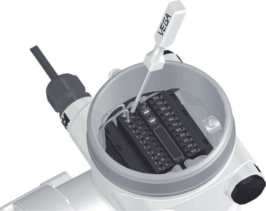
Contents

                  9    Dismount................................................................................................................................. 68
                       9.1 Dismounting steps.......................................................................................................... 68
                       9.2 Disposal.......................................................................................................................... 68
                  10 Supplement............................................................................................................................. 69
                     10.1 Technical data................................................................................................................. 69
                     10.2 Dimensions..................................................................................................................... 74
                     10.3 Industrial property rights.................................................................................................. 79
                     10.4 Trademark....................................................................................................................... 79
42374-EN-210311

                                                            Safety instructions for Ex areas
                                                            Take note of the Ex specific safety instructions for Ex applications.
                                                            These instructions are attached as documents to each instrument
                                                            with Ex approval and are part of the operating instructions.
                                                            Editing status: 2021-03-04

                  WEIGHTRAC 31 • Four-wire 4 … 20 mA/HART                                                                                                       3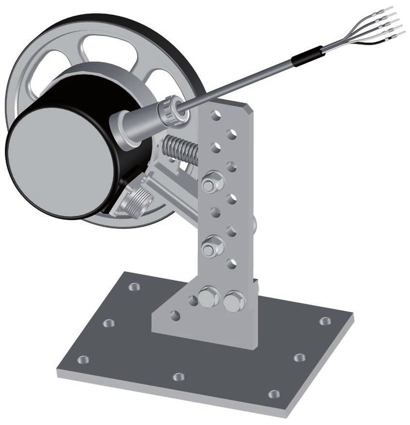
1 About this document

                            1     About this document
                            1.1    Function
                            This instruction provides all the information you need for mounting,
                            connection and setup as well as important instructions for mainte-
                            nance, fault rectification, the exchange of parts and the safety of the
                            user. Please read this information before putting the instrument into
                            operation and keep this manual accessible in the immediate vicinity
                            of the device.

                            1.2    Target group
                            This operating instructions manual is directed to trained personnel.
                            The contents of this manual must be made available to the qualified
                            personnel and implemented.

                            1.3    Symbols used
                            Document ID
                            This symbol on the front page of this instruction refers to the Docu-
                            ment ID. By entering the Document ID on www.vega.com you will
                            reach the document download.
                            Information, note, tip: This symbol indicates helpful additional infor-
                            mation and tips for successful work.
                            Note: This symbol indicates notes to prevent failures, malfunctions,
                            damage to devices or plants.
                            Caution: Non-observance of the information marked with this symbol
                            may result in personal injury.
                            Warning: Non-observance of the information marked with this symbol
                            may result in serious or fatal personal injury.
                            Danger: Non-observance of the information marked with this symbol
                            results in serious or fatal personal injury.
                            Ex applications
                            This symbol indicates special instructions for Ex applications.
                        •   List
                            The dot set in front indicates a list with no implied sequence.
                        1   Sequence of actions
                            Numbers set in front indicate successive steps in a procedure.
                            Battery disposal
                            This symbol indicates special information about the disposal of bat-
                            teries and accumulators.
                                                                                                      42374-EN-210311

4                                                        WEIGHTRAC 31 • Four-wire 4 … 20 mA/HART
2 For your safety

                                              2     For your safety
                                              2.1    Authorised personnel
                                              All operations described in this documentation must be carried out
                                              only by trained, qualified personnel authorised by the plant operator.
                                              During work on and with the device, the required personal protective
                                              equipment must always be worn.

                                              2.2    Appropriate use
                                              WEIGHTRAC 31 is a sensor for continuous mass flow detection on
                                              conveyor belts as well as screw or chain conveyors.
                                              You can find detailed information about the area of application in
                                              chapter "Product description".
                                              Operational reliability is ensured only if the instrument is properly
                                              used according to the specifications in the operating instructions
                                              manual as well as possible supplementary instructions.

                                              2.3    Warning about incorrect use
                                              Inappropriate or incorrect use of this product can give rise to applica-
                                              tion-specific hazards, e.g. vessel overfill through incorrect mounting
                                              or adjustment. Damage to property and persons or environmental
                                              contamination can result. Also, the protective characteristics of the
                                              instrument can be impaired.

                                              2.4    General safety instructions
                                              This is a state-of-the-art instrument complying with all prevailing
                                              regulations and directives. The instrument must only be operated in a
                                              technically flawless and reliable condition. The operator is responsi-
                                              ble for the trouble-free operation of the instrument. When measuring
                                              aggressive or corrosive media that can cause a dangerous situation
                                              if the instrument malfunctions, the operator has to implement suitable
                                              measures to make sure the instrument is functioning properly.
                                              The safety instructions in this operating instructions manual, the na-
                                              tional installation standards as well as the valid safety regulations and
                                              accident prevention rules must be observed by the user.
                                              For safety and warranty reasons, any invasive work on the device
                                              beyond that described in the operating instructions manual may be
                                              carried out only by personnel authorised by the manufacturer. Arbi-
                                              trary conversions or modifications are explicitly forbidden. For safety
                                              reasons, only the accessory specified by the manufacturer must be
                                              used.
                                              To avoid any danger, the safety approval markings and safety tips on
                                              the device must also be observed.
42374-EN-210311

                                              This measuring system uses gamma rays. Therefore take note of the
                                              instructions for radiation protection in chapter "Product description".
                                              Any work on the source container may only be carried out under the
                                              supervision of a qualified radiation protection officer.

                  WEIGHTRAC 31 • Four-wire 4 … 20 mA/HART                                                               5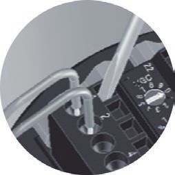
2 For your safety

                    2.5     EU conformity
                    The device fulfils the legal requirements of the applicable EU direc-
                    tives. By affixing the CE marking, we confirm the conformity of the
                    instrument with these directives.
                    The EU conformity declaration can be found on our homepage.

                    Electromagnetic compatibility
                    Instruments in four-wire or Ex-d-ia version are designed for use in an
                    industrial environment. Nevertheless, electromagnetic interference
                    from electrical conductors and radiated emissions must be taken into
                    account, as is usual with class A instruments according to EN 61326-
                    1. If the instrument is used in a different environment, the electromag-
                    netic compatibility to other instruments must be ensured by suitable
                    measures.

                    2.6     NAMUR recommendations
                    NAMUR is the automation technology user association in the process
                    industry in Germany. The published NAMUR recommendations are
                    accepted as the standard in field instrumentation.
                    The device fulfils the requirements of the following NAMUR recom-
                    mendations:
                    •   NE 21 – Electromagnetic compatibility of equipment
                    •   NE 43 – Signal level for fault information from measuring transduc-
                        ers
                    •   NE 53 – Compatibility of field devices and display/adjustment
                        components
                    •   NE 107 – Self-monitoring and diagnosis of field devices
                    For further information see www.namur.de.

                    2.7     Installation and operation in the USA and
                            Canada
                    This information is only valid for USA and Canada. Hence the follow-
                    ing text is only available in the English language.
                    Installations in the US shall comply with the relevant requirements of
                    the National Electrical Code (ANSI/NFPA 70).
                    Installations in Canada shall comply with the relevant requirements of
                    the Canadian Electrical Code.

                    2.8     Environmental instructions
                    Protection of the environment is one of our most important duties.
                    That is why we have introduced an environment management system
                    with the goal of continuously improving company environmental pro-
                    tection. The environment management system is certified according
                    to DIN EN ISO 14001.
                                                                                               42374-EN-210311

                    Please help us fulfil this obligation by observing the environmental
                    instructions in this manual:
                    •   Chapter " Packaging, transport and storage"
                    •   Chapter " Disposal"

6                                                WEIGHTRAC 31 • Four-wire 4 … 20 mA/HART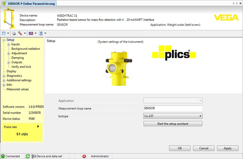
3 Product description

                                              3        Product description
                                              3.1       Configuration
                  Type label                 The type label contains the most important data for identification and
                                             use of the instrument:

                                                   1
                                                   2

                                                   3                                                             9
                                                                                                                 10
                                                   4
                                                   5
                                                   6                                                             9

                                                   7
                                                   8
                                              Fig. 1: Layout of the type label (example)
                                              1    Instrument type
                                              2    Product code
                                              3    Electronics
                                              4    Protection rating
                                              5    Ambient temperature
                                              6    Measurement width
                                              7    Hardware and software version
                                              8    Order number
                                              9    Serial number of the instrument
                                              10   ID numbers, instrument documentation

                  Serial number - Instru-    The type label contains the serial number of the instrument. With it
                  ment search                you can find the following instrument data on our homepage:
                                              •    Product code (HTML)
                                              •    Delivery date (HTML)
                                              •    Order-specific instrument features (HTML)
                                              •    Operating instructions and quick setup guide at the time of ship-
                                                   ment (PDF)
                                              •    Order-specific sensor data for an electronics exchange (XML)
                                              •    Test certificate (PDF) - optional
                                              Move to " www.vega.com" and enter in the search field the serial
                                              number of your instrument.
                                              Alternatively, you can access the data via your smartphone:
                                              •    Download the VEGA Tools app from the " Apple App Store" or the
                                                   " Google Play Store"
                                              •    Scan the DataMatrix code on the type label of the instrument or
                                              •    Enter the serial number manually in the app
42374-EN-210311

                  Scope of this operating    This operating instructions manual applies to the following instrument
                  instructions               versions:
                                              •    Hardware from 1.0.6

                  WEIGHTRAC 31 • Four-wire 4 … 20 mA/HART                                                              7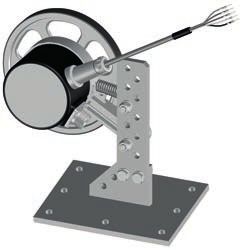
3 Product description

                        •    Software from 2.1.0 1)

                        •    Hardware from 2.0.0
                        •    Software from 3.0.0

Electronics versions    The instrument is available in different electronics versions. Each ver-
                        sion can be identified via the product code on the type label:
                        •    Standard electronics type PROTRACH.-XX

Scope of delivery       The scope of delivery encompasses:
                        •    Radiometric sensor
                        •    Measuring frame (optional)
                        •    Mounting accessories
                        •    Documentation
                        •    Bluetooth module (optional)
                             –– This operating instructions manual
                             –– Ex-specific "Safety instructions" (with Ex versions)
                             –– If necessary, further certificates

                                               4
                                                                                1

                               3

                                                                                                          3

                                                        5

                              2                        5

                        Fig. 2: WEIGHTRAC 31
                        1    Source container (e.g. SHLD-1)
                        2    WEIGHTRAC 31
                        3    Support stand
                        4    Crossbeam
                        5    Clamp collars

                        Note:
                                                                                                                42374-EN-210311

                        The appropriate source container (e.g. SHLD-1) must be ordered
                        separately.

                        1)
                             It is not possible to update the software to 3.0.0. In this case the electronics
                             module must be exchanged.

8                                                           WEIGHTRAC 31 • Four-wire 4 … 20 mA/HART
3 Product description

                                              3.2    Principle of operation
                  Application area           The instrument is suitable for bulk solid applications on conveyor belts
                                             and screw conveyors. There are application possibilities in nearly all
                                             areas of industry.

                  Functional principle        In radiometric measurement, a Caesium-137 or Cobalt-60 isotope
                                              emits focussed gamma rays that are attenuated when penetrating
                                              the conveyor belt and the medium. The PVT detector on the lower
                                              side of the conveyor belt receives the radiation, whose strength is
                                              proportional to the density. The measuring principle has proven to be
                                              very reliable in conjunction with extreme process conditions because
                                              it measures contactlessly from outside through the conveyor belt. The
                                              measuring system ensures maximum safety, reliability and plant avail-
                                              ability, independently of the medium and its properties.

                                              3.3    Packaging, transport and storage
                  Packaging                  Your instrument was protected by packaging during transport. Its
                                             capacity to handle normal loads during transport is assured by a test
                                             based on ISO 4180.
                                              The packaging consists of environment-friendly, recyclable card-
                                              board. For special versions, PE foam or PE foil is also used. Dispose
                                              of the packaging material via specialised recycling companies.

                  Transport                  Transport must be carried out in due consideration of the notes on the
                                             transport packaging. Nonobservance of these instructions can cause
                                             damage to the device.

                  Transport inspection       The delivery must be checked for completeness and possible transit
                                             damage immediately at receipt. Ascertained transit damage or con-
                                             cealed defects must be appropriately dealt with.

                  Storage                     Up to the time of installation, the packages must be left closed and
                                              stored according to the orientation and storage markings on the
                                              outside.
                                              Unless otherwise indicated, the packages must be stored only under
                                              the following conditions:
                                              •   Not in the open
                                              •   Dry and dust free
                                              •   Not exposed to corrosive media
                                              •   Protected against solar radiation
                                              •   Avoiding mechanical shock and vibration
                  Storage and transport       •   Storage and transport temperature see chapter " Supplement -
                  temperature                     Technical data - Ambient conditions"
                                              •   Relative humidity 20 … 85 %
42374-EN-210311

                  Lifting and carrying       With instrument weights of more than 18 kg (39.68 lbs) suitable and
                                             approved equipment must be used for lifting and carrying.

                  WEIGHTRAC 31 • Four-wire 4 … 20 mA/HART                                                             9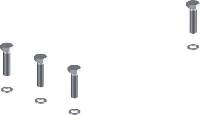
3 Product description

                          3.4    Accessories
PLICSCOM                  The display and adjustment module is used for measured value indi-
                          cation, adjustment and diagnosis.
                          The integrated Bluetooth module (optional) enables wireless adjust-
                          ment via standard adjustment devices.

VEGACONNECT               The interface adapter VEGACONNECT enables the connection of
                          communication-capable instruments to the USB interface of a PC.

VEGADIS 81                The VEGADIS 81 is an external display and adjustment unit for VEGA
                          plics® sensors.

VEGADIS 82                VEGADIS 82 is suitable for measured value indication and adjustment
                          of sensors with HART protocol. It is looped into the 4 … 20 mA/HART
                          signal cable.

Electronics module -      The electronics module PT30… is a replacement part for radiometric
PT30                      sensors WEIGHTRAC 31.
                          It is located in the large electronics and connection compartment.
                          The electronics module can only be exchanged by VEGA service
                          technician.

Supplementary electron-   The supplementary electronics module PROTRAC.ZE… is a replace-
ics module - PROTRAC.     ment part for radiometric sensors WEIGHTRAC 31.
ZE
                          It is located in the lateral adjustment and connection compartment.

Basic mounting set        If you have ordered WEIGHTRAC 31 without a measuring frame, a
                          basic mounting set is enclosed with the instrument. It includes every-
                          thing needed to fasten the measuring tube reliably.

Measuring frame for       The corresponding measuring frame and mounting accessories can
mounting                  be ordered optionally.

Tachometer                Use a tachometer for detection of the belt speed. The tachometer can
                          be connected to the input of the WEIGHTRAC 31.

Reference absorber        The reference absorber is a test facility for the WEIGHTRAC 31. It
                          is suitable for reference measurement on conveyor belts and screw
                          conveyors. A certain measured value can be exactly reproduced for
                          test purposes when a conveying system is empty.

Gamma modulator           In order to exclude external interference radiation, you can mount a
                          gamma modulator in front of the source holder. This allows reliable
                          measurement even when interference radiation occurs.
                                                                                                   42374-EN-210311

10                                                    WEIGHTRAC 31 • Four-wire 4 … 20 mA/HART
3 Product description
Fig. 3: Gamma modulator (optional) for uninterrupted measurement even with
interference radiation
1 Gamma modulator (mounted on the source holder)
For ambient temperatures up to 120 °C (248 °C) the gamma modula-
tor is optionally available with water cooling.
Any number of devices can be synchronized. To synchronize several
gamma modulators, you need a controller.
3.5 Corresponding source container
An isotope in a suitable source container (e.g. SHLD-1) is the prereq-
uisite for a radiometric measurement setup.
The handling of radioactive substances is regulated by law. The radia-
tion protection rules of the country in which the system is operated
apply first and foremost.
In Germany, for example, the current radiation protection ordinance
(StrlSchV) based on the Atomic Energy Law (AtG) applies.
The following points are important for measurement with radiometric
methods:
Handling permit A handling permit is required for operation of a system using gamma
42374-EN-210311
rays. This permit is issued by the respective government office or the
responsible authority (in Germany, for example, offices for environ-
mental protection, trade supervisory boards, etc.)
You can find further instructions in the operating instructions manual
of the source container.
WEIGHTRAC 31 • Four-wire 4 … 20 mA/HART 113 Product description
General instructions for When handling radioactive substances, unnecessary radiation
radiation protection exposure must be avoided. An unavoidable radiation exposure must
be kept as low as possible. Take note of the following three important
measures:
1 2 3
Fig. 4: Measures for protection against radioactive radiation
1 Shielding
2 Time
3 Distance
Shielding: Provide good shielding between the source and yourself
as well as all other persons. Special source containers (e.g. SHLD-1)
as well as all materials with high density (e.g. lead, iron, concrete,
etc.) provide effective shielding.
Time: Stay as short a time as possible in radiation exposed areas.
Distance: Your distance to the source should be as large as possible.
The local dose rate of the radiation decreases in proportion to the
square of the distance to the radiation source.
Radiation safety officer The plant operator must appoint a radiation safety officer with the
necessary expert knowledge. He is responsible for ensuring that the
radiation protection ordinance is complied with and for implementing
all radiation protection measures.
Control area Control areas are areas in which the local dose rate exceeds a certain
value. Only persons who undergo official dose monitoring are allowed
into these control areas. You can find the respectively valid limit values
for control areas in the guideline of the respective authority (in Ger-
many, for example, the radiation protection ordinance).
We are at your disposal for further information concerning radiation
protection and regulations in other countries.
42374-EN-210311
12 WEIGHTRAC 31 • Four-wire 4 … 20 mA/HART4 Mounting
4 Mounting
4.1 General instructions
Switch off source The source container is part of the measuring system. In case the
source container is already equipped with an active isotope, the
source container must be locked before mounting.
Danger:
Before mounting; make sure that the source is securely closed. Use
a padlock to secure the source container in the closed condition and
prevent it from being inadvertently opened.
Protection against mois- Protect your instrument against moisture ingress through the following
ture measures:
• Use a suitable connection cable (see chapter " Connecting to
power supply")
• Tighten the cable gland or plug connector
• Lead the connection cable downward in front of the cable entry or
plug connector
This applies mainly to outdoor installations, in areas where high
humidity is expected (e.g. through cleaning processes) and on cooled
or heated vessels.
Note:
Make sure that during installation or maintenance no moisture or dirt
can get inside the instrument.
To maintain the housing protection, make sure that the housing lid is
closed during operation and locked, if necessary.
Process conditions Note:
For safety reasons, the instrument must only be operated within the
permissible process conditions. You can find detailed information on
the process conditions in chapter " Technical data" of the operating
instructions or on the type label.
Hence make sure before mounting that all parts of the instrument ex-
posed to the process are suitable for the existing process conditions.
These are mainly:
• Active measuring component
• Process fitting
• Process seal
Process conditions in particular are:
• Process pressure
• Process temperature
• Chemical properties of the medium
•
42374-EN-210311
Abrasion and mechanical influences
WEIGHTRAC 31 • Four-wire 4 … 20 mA/HART 134 Mounting
Cable glands Metric threads
In the case of instrument housings with metric thread, the cable
glands are screwed in at the factory. They are sealed with plastic
plugs as transport protection.
You have to remove these plugs before electrical connection.
NPT thread
In the case of instrument housings with self-sealing NPT threads, it is
not possible to have the cable entries screwed in at the factory. The
free openings for the cable glands are therefore covered with red dust
protection caps as transport protection.
Prior to setup you have to replace these protective caps with ap-
proved cable glands or close the openings with suitable blind plugs.
The suitable cable glands and blind plugs come with the instrument.
4.2 Mounting instructions
Installation position Note:
During the planning, our specialists will analyse the conditions of the
measurement loop to dimension the isotope accordingly.
You get a "Source Sizing" document specifying the required source
activity and containing all relevant mounting information for your
measuring point.
You must follow the instructions in this "Source Sizing" document in
addition to the following mounting instructions.
The following mounting information is applicable as long as there is
nothing else specified in the "Source Sizing" document.
You can position and mount WEIGHTRAC 31 in the measuring frame
from both sides.
Direct the exit angle of the source container to the WEIGHTRAC 31.
Mount the source container at the specified distance to the conveyor
belt. Secure the area with a safety fence and protective grating so that
no one can reach into the dangerous area.
You can find information on protective barriers and the mounting
of the corresponding source container in the operating instructions
manual of the source container.
Basic mounting set If you have ordered WEIGHTRAC 31 without measuring frame, a
basic mounting set is enclosed with the instrument.
Determine the mounting position of the sensor in advance.
1. Fasten the mounting bracket (6) to your conveyor belt.
You can either weld the mounting bracket (6) to your system or
fasten it with screws through the two ø9 mm (0.35 in) holes.
2. Place two clamp collars (4) onto the premounted mounting brack-
42374-EN-210311
ets (6).
14 WEIGHTRAC 31 • Four-wire 4 … 20 mA/HART4 Mounting
1
2
3
4
5
4
6
2
7
Fig. 5: Mounting of the sensor with the basic mounting set
1 Screws M6 x 120 (4 pieces)
2 Wedge lock washer M6 Nordlock (8 pieces)
3 Cover plate (2 pieces)
4 Clamp collar (4 pieces) PA
5 Sensor
6 Mounting bracket
7 Nut M6 (4 pieces)
Note:
Mount the instrument housing of the sensor on an easily accessible
side of the conveyor belt so that the instrument is easily accessible for
operation and service.
3. Move the sensor (5) laterally beneath the conveyor belt and place
the sensor in the two clamp collars (4).
Position the measuring width of the sensor below the conveyor
belt as close as possible to the center. Make sure that there is
sufficient distance between sensor and conveyor belt when the
belt is loaded.
42374-EN-210311
4. Place the other two clamp collars (4) according to the illustration
above the clamp collars that are already in place (4).
5. Place a metallic cover plate (3) according to the illustration on
each upper clamp collar (4).
WEIGHTRAC 31 • Four-wire 4 … 20 mA/HART 154 Mounting
6. Insert the screws (1), each with one wedge lock washer (2),
through the clamp collars (4).
7. Place a wedge lock washer (2) from below on each screw (1) and
screw one nut (7) onto each screw.
8. Align the clamp collars (4) and tighten the nuts (7) evenly with
8 Nm (5.9 lb ft).
9. Check if the sensor (5) is fastened correctly.
Measuring frame (op- - Conveyor belts
tional) Mount the measuring frame in such a way that the measurement tube
of WEIGHTRAC 31 is below the conveyor belt (tight span).
Keep a distance of at least 10 mm (0.4 in) between the conveyor belt
and the measurement tube of WEIGHTRAC 31.
- Screw conveyors
Mount the measuring frame at a position on the spiral conveyor where
the product is transported steadily. Avoid places where the product
accumulates or falls back over the worm shaft.
- Chain conveyors
When mounting the WEIGHTRAC 31 on a chain conveyor, the instal-
lation angle is very important for optimal irradiation.
Follow the instructions in the "Source Sizing" document.
Mounting of the measuring frame (optional)
The measuring frame with mounting accessories can be selected as
an option. If you have ordered WEIGHTRAC 31 with measuring frame,
then proceed as follows.
Mounting - Crossbeam
Before fastening the support stands, we recommend premounting the
measuring frame. By doing this you can easily lay out the holes for
fastening the unit to the conveyor belt.
To mount the measuring frame you need a torque wrench (45 Nm or
8 Nm) and two socket wrenches of size 16 and 10.
1. Place the crossbeam (4) on the upper holding fixtures of the two
support stands (6).
Make sure that the crossbeam (4) has an excess length of ap-
prox. 30 mm on both sides.
42374-EN-210311
16 WEIGHTRAC 31 • Four-wire 4 … 20 mA/HART4 Mounting
1
2
3
4
2
5
6
Fig. 6: Mounting the crossbeam
1 Screws M10 x 40 (12 pcs.)
2 Wedge lock washer M10 Nordlock (24 pieces)
3 Crossbeam (1 piece)
4 Toe clamps (4 pieces)
5 Nut M10 (12 pieces)
6 Support stand (2 pieces)
2. Place the four clamping claws (4) with the corrugation downwards
into the crossbeam (3).
3. Insert the screws (1) with one wedge lock washer (2) through the
clamping claws (4).
4. Place a wedge lock washer (2) from below on each screw (1) and
screw one nut (5) onto each screw.
5. Align the crossbeam (3) with the upper holding fixtures of the
support stands (6) and tighten the nuts (5) evenly with 45 Nm
(33.2 lb ft).
Mounting - Support stand
1. Place the premounted measuring frame above the conveyor belt
and determine a suitable position for mounting the support stands
(6).
42374-EN-210311
Mount the measuring frame as well centered as possible and
at an angle of 90° above the conveyor belt. Keep enough lateral
distance to the conveyor belt.
WEIGHTRAC 31 • Four-wire 4 … 20 mA/HART 174 Mounting
2. Drill the through-holes for the support stands (6) according to the
following drilling plan.
The through-holes in the support stands (6 in each) are suitable
for screws of size M10.
The screws (14) and the washers (15) for fastening on the con-
veyor belt are not included in the scope of delivery.
120 mm
(4.72")
ø1 15 mm
2 (0.59")
(0. mm
47
")
270 mm
300 mm
(10.63")
(11.81")
150 mm
15 mm
(0.59")
(5.91")
Fig. 7: Drilling plan for support stands
3. Use suitable washers (15) for mounting the support stands (6).
14
15
42374-EN-210311
Fig. 8: Mounting the support stands
14 Screw M10 (24 pieces) - provided by the customer
15 Washer M10 (24 pieces) - provided by the customer
4. Tighten the screws (14) evenly with 45 Nm (33.2 lb ft).
18 WEIGHTRAC 31 • Four-wire 4 … 20 mA/HART4 Mounting
Mounting - Sensor
1. Place two of the clamp collars (11) on the fastening brackets of
the support stands (6).
8
9
10
11
13
11
9
12
Fig. 9: Mounting the sensor in the measuring frame
8 Screws M6 x 120 (4 pieces)
9 Wedge lock washer M6 Nordlock (8 pieces)
10 Cover plate (2 pieces)
11 Clamp collar (4 pieces)
12 Nut M6 (4 pieces)
13 Sensor
Note:
Mount the instrument housing of the sensor on an easily accessible
side of the conveyor belt so that the instrument is easily accessible for
operation and service.
2. Insert the sensor (13) laterally into the measuring frame beneath
42374-EN-210311
the conveyor belt and place the sensor in the two clamp collars
(11).
Position the measuring width of the sensor below the conveyor
belt as close as possible to the center. Make sure that there is
WEIGHTRAC 31 • Four-wire 4 … 20 mA/HART 194 Mounting
sufficient distance between sensor and conveyor belt when the
belt is loaded.
3. Place the other two clamp collars (11) according to the illustration
above the clamp collars that are already in place (11).
4. Place a metallic cover plate (10) according to the illustration on
each upper clamp collar (11).
5. Insert the screws (8), each with one wedge lock washer (9),
through the clamp collars (11).
6. Place a wedge lock washer (9) from below on each screw (8) and
screw one nut (12) on each of the screws.
7. Align the clamp collars (11) and tighten the nuts (12) evenly with
8 Nm (5.9 lb ft).
8. Check if the sensor (13) is fastened correctly.
Mounting - Source container
7
1
2
5
Fig. 10: Mounting the source container on the measuring frame
1 Screw M10 x 65 (4 pieces)
2 Wedge lock washer M10 Nordlock (8 pieces)
5 Nut M10 (4 pieces)
7 Source holder (SHLD-1)
1. Place the closed and locked source container (7) from above onto
the measuring frame.
The source container is very heavy. Therefore use a suitable lifting
device. For this purpose the source container is equipped with a
42374-EN-210311
suitable eye-bolt for a lifting hook, etc.
Note:
Select the alignment of the source holder so that the rotary mecha-
nism of the source holder is located on the easily accessible side of
the conveyor belt. This makes the rotary mechanism easily accessible
20 WEIGHTRAC 31 • Four-wire 4 … 20 mA/HART4 Mounting
for operation and service at all times. This only applies to source hold-
ers with symmetrical beam exit angle.
2. Align the source container (7) with the holes.
Make sure that the source container is placed in the correct direc-
tion on the crossbeam.
3. Insert the screws (1) with one wedge lock washer (2) through the
flange of the source container (7).
4. Place a wedge lock washer (2) from below on each screw (1) and
screw one nut (5) onto each screw.
5. Align the source container (7) and tighten the nuts (5) evenly with
45 Nm (33.2 lb ft).
The mounting of the measuring frame is finished.
Strain the measuring frame
Large measuring frames can deflect when subjected to strong vibra-
tion or strong winds.
Therefore, measuring frames used on conveyor belts with widths over
1600 mm (63 in) should be strained with steel cables.
For this there are two fastening straps on the side of the support stand
of the measuring frame.
Determine the fastening points on your conveyor belt according to the
local conditions.
Provide the straining screws (1) for each cable to ensure reliable
straining of the measuring frame.
Make sure that the measuring frame is perfectly vertical after strain-
ing.
1
42374-EN-210311
Fig. 11: Straining the measuring frame
1 Straining screw
WEIGHTRAC 31 • Four-wire 4 … 20 mA/HART 214 Mounting
Protection against heat If the max. ambient temperature is exceeded, you must take suitable
measures to protect the instrument against overheating.
You can protect the instrument by providing a suitable insulation
against the heat or mounting the instrument further away from the
heat source.
Make sure these measures are taken into account already in the plan-
ning stage. If you want to carry out such measures later on, contact
our specialists to ensure that the accuracy of the application is not
impaired.
If these measures are not sufficient to maintain the max. ambient
temperature, you could consider using the water or air cooling system
we offer for WEIGHTRAC 31.
The cooling system must also be included in the calculations for the
measuring point. Contact our specialists regarding the dimensioning
of the cooling.
Mounting of the tachom- The speed value of the conveyor belt, the conveyor belt is absolutely
eter necessary for mass flow determination.
Apart from other possibilities, a tachometer can be used.
Positioning of the tachometer
Load applied only to one side can cause damage of the tachometer.
To avoid this, you should select a position underneath the conveyor
belt where the impeller is nearly vertical to the conveyor belt.
The holder of the tachometer is thus premounted to carrier plate with
an angle of 115°
1
10
5°
Fig. 12: Impeller of the tachometer, vertically to the conveyor belt
1 Conveyor belt
Direction of rotation
Mount the tachometer according to the following illustration. The cor-
rect orientation of the impeller is important. In case of fluctuations, e.g.
by alternating load, the impeller can draw aside.
42374-EN-210311
If possible, mount the tachometer close to a support wheel because
in these positions the conveyor belt runs evenly.
For height adjustment, the angle bracket of the tachometer is pro-
vided with several holes.
22 WEIGHTRAC 31 • Four-wire 4 … 20 mA/HART4 Mounting
Select the height adjustment so that the spring of the impeller is
slightly pre-loaded with empty conveyor belt.
1
2
3
Fig. 13: Direction of rotation of the tachometer
1 Conveyor belt
2 Support wheel of the conveyor belt
3 Spring for pre-loading the impeller
42374-EN-210311
WEIGHTRAC 31 • Four-wire 4 … 20 mA/HART 235 Connecting to power supply
5 Connecting to power supply
5.1 Preparing the connection
Safety instructions Always keep in mind the following safety instructions:
• The electrical connection must only be carried out by trained,
qualified personnel authorised by the plant operator.
• If overvoltage surges are expected, overvoltage arresters should
be installed.
Warning:
Only connect or disconnect in de-energized state.
Voltage supply via mains In this case, the instrument is designed in protection class I. To main-
voltage tain this protection class, it is absolutely necessary that the ground
conductor be connected to the internal ground terminal. Take note of
the national installation regulations.
Supply voltage and current output are carried on separate connection
cables if reliable separation is required. The supply voltage range can
differ depending on the instrument version.
The data for power supply are specified in chapter " Technical data".
Select connection cable General requirements
• Make sure that the cable used has the required temperature resist-
ance and fire safety for max. occurring ambient temperature
• Use cable with round cross section for instruments with housing
and cable gland. To ensure the seal effect of the cable gland (IP
protection rating), find out which cable outer diameter the cable
gland is suitable for.
• Use a cable gland fitting the cable diameter.
• Unused cable glands do not offer sufficient protection against
moisture and must be replaced by blind plugs.
Voltage supply
For power supply, an approved, three-wire installation cable with PE
conductor is required.
Signal cable
The 4 … 20 mA current output is connected with standard two-wire
cable without shielding. If electromagnetic interference is expected
which is above the test values of EN 61326-1 for industrial areas,
shielded cable should be used.
Cable glands Metric threads
In the case of instrument housings with metric thread, the cable
glands are screwed in at the factory. They are sealed with plastic
plugs as transport protection.
42374-EN-210311
You have to remove these plugs before electrical connection.
NPT thread
In the case of instrument housings with self-sealing NPT threads, it is
not possible to have the cable entries screwed in at the factory. The
24 WEIGHTRAC 31 • Four-wire 4 … 20 mA/HART5 Connecting to power supply
free openings for the cable glands are therefore covered with red dust
protection caps as transport protection.
Before setup you have to replace these protective caps with approved
cable glands or close the openings with suitable blind plugs. Unused
cable glands do not provide sufficient protection against moisture and
must be replaced with blind plugs.
The suitable cable glands and blind plugs come with the instrument.
Cable screening and If shielded cable is required, connect the cable screen on both ends
grounding to ground potential. In the sensor, the screen must be connected
directly to the internal ground terminal. The ground terminal on the
outside of the housing must be connected to the potential equalisa-
tion (low impedance).
If potential equalisation currents are expected, the connection on the
processing side must be made via a ceramic capacitor (e. g. 1 nF,
1500 V). The low-frequency potential equalisation currents are thus
suppressed, but the protective effect against high frequency interfer-
ence signals remains.
Warning:
Significant potential differences exist inside galvanization plants as
well as on vessels with cathodic corrosion protection. Considerable
equalisation currents can flow over the cable screen if the screen is
grounded on both ends.
To avoid this, the cable screen in such applications must be con-
nected only on one end to ground potential in the switching cabinet.
The cable screen must not be connected to the inner ground terminal
in the sensor and the outer ground terminal on the housing must not
be connected to potential equalization!
Information:
The metal parts of the instrument are conductively connected with
the inner and outer ground terminal on the housing. This connection
is either a direct metallic connection or, in case of instruments with
external electronics, a connection via the screen of the special con-
nection cable.
You can find specifications on the potential connections inside the
instrument in chapter "Technical data".
Connection technology The voltage supply and signal output are connected via the spring-
loaded terminals in the housing.
Connection to the display and adjustment module or to the interface
adapter is carried out via contact pins in the housing.
Connection procedure Proceed as follows:
The procedure applies to instruments without explosion protection.
42374-EN-210311
1. Unscrew the big housing cover
2. Loosen compression nut of the cable gland and remove blind
plug
WEIGHTRAC 31 • Four-wire 4 … 20 mA/HART 255 Connecting to power supply
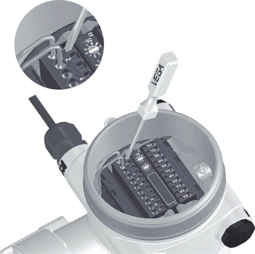
3. Remove approx. 10 cm (4 in) of the cable mantle, strip approx.
1 cm (0.4 in) of insulation from the ends of the individual wires
4. Insert the cable into the sensor through the cable entry
1
Fig. 14: Connection steps 4 and 5
1 Locking of the terminal blocks
5. Insert a small slotted screwdriver firmly into the rectangular lock
openings of the respective connection terminal
6. Insert the wire ends into the round openings of the terminals ac-
cording to the wiring plan
Information:
Solid cores as well as flexible cores with cable end sleeves are
inserted directly into the terminal openings. In case of flexible cores
without end sleeves, press the rectangular lock opening with a small
screwdriver; the terminal opening is freed. When the screwdriver is
released, the terminal opening closes again.
7. Check the hold of the wires in the terminals by lightly pulling on
them
To loosen a line, insert a small slotted screwdriver firmly into the
rectangular lock opening according to the illustration
8. Connect the shielding to the internal ground terminal, connect the
external ground terminal to potential equalisation
9. Tighten the compression nut of the cable entry gland. The seal
ring must completely encircle the cable
10. Screw the housing lid back on
42374-EN-210311
The electrical connection is finished.
Information:
The terminal blocks are pluggable and can be detached from the
electronics. To do this, loosen the two lateral locking levers of the
terminal block with a small screwdriver. When loosening the locking,
26 WEIGHTRAC 31 • Four-wire 4 … 20 mA/HART5 Connecting to power supply
the terminal block is automatically squeezed out. It must snap in place
when re-inserted.
5.2 Connection - Mass flow determination
Non-Ex instruments and instruments with non-intrinsically safe
current output
Electronics and con-
nection compartment 10
- Non-Ex instruments and
instruments with non-
22
/L
1
22 21 20 19 18 17 16 15 14 13 12
1
intrinsically safe current 1
/N
2
output 9
PE
4
2
5
8
6
6
7
9
3
10 11
4 5
11
12
Fig. 15: Electronics and connection compartment with non-Ex instruments and
instruments with non-intrinsically safe current output
1 Voltage supply
2 Relay output
3 Signal output 4 … 20 mA/HART active
4 Signal output 4 … 20 mA/HART passive
5 Signal input 4 … 20 mA
6 Switching input for NPN transistor
7 Switching input floating
8 Transistor output
9 Interface for sensor-sensor communication (MGC)
10 Setting the bus address for sensor-sensor communication (MGC)2)
Adjustment and con-
nection compartment 2
- Non-Ex instruments and
instruments with non-
intrinsically safe current
output
5 6 7 8 1
Fig. 16: Adjustment and connection compartment with non-Ex instruments and
instruments with non-intrinsically safe current output
42374-EN-210311
1 Terminals for the external display and adjustment unit
2 Contact pins for the display and adjustment module or interface adapter
2)
MGC = Multi Gauge Communication
WEIGHTRAC 31 • Four-wire 4 … 20 mA/HART 275 Connecting to power supply
Instruments with intrinsically safe current output
You can find detailed information on the explosion-protected versions
(Ex-ia, Ex-d) in the Ex-specific safety instructions. These safety
instructions are part of the scope of delivery and come with the Ex-
approved instruments.
Electronics and connec-
tion compartment - In- 8
struments with intrinsi-
cally safe current output
22
/L
1
22 21 20 19 18 17 16 15 14 13 12
1
1
/N
2
7
PE
4
2
5
6
6
4
5
3
11
12
Fig. 17: Electronics and connection compartment (Ex-d) with instruments with
intrinsically safe current output
1 Voltage supply
2 Relay output
3 Signal input 4 … 20 mA
4 Switching input for NPN transistor
5 Switching input floating
6 Transistor output
7 Interface for sensor-sensor communication (MGC)
8 Setting the bus address for sensor-sensor communication (MGC)3)
Adjustment and connec-
tion compartment - In- 2
struments with intrinsi-
cally safe current output
3
(+)1 2(-) 5 6 7 8
1 4
Fig. 18: Adjustment and connection compartment (Ex-ia) with instruments with
intrinsically safe current output
42374-EN-210311
1 Terminals for intrinsically safe signal output 4 … 20 mA/HART (active)
2 Contact pins for the display and adjustment module or interface adapter
3 Terminals for the external display and adjustment unit
4 Ground terminal
3)
MGC = Multi Gauge Communication
28 WEIGHTRAC 31 • Four-wire 4 … 20 mA/HART5 Connecting to power supply
5.3 Connection - Summation
Electronics and connec- Several instruments can be cascaded to measure also broad con-
tion compartment - sum- veyor belts. The measuring ranges of the instruments must overlap.
mation
Cascading means that two or several instruments are connected
which can together cover a longer measuring range.
The instrument acts as Primary instrument and all other instruments
operate as Secondary instruments.
The pulse rates of all instruments are summed in the Primary instru-
ment and converted into a common signal.
The Primary instrument must have the function "Mass flow detection".
For this purpose, select under the menu item " Setup - Application"
the function "Mass flow detection".
Set the address setting (MGC) on the Primary instrument to "99".
For this, the Secondary instruments must be defined as "Summation
Secondary". Select under the menu item " Setup - Application" the
function "Summation Secondary".
The address setting (MGC) on the Secondary instruments can be
freely selected. Only the address "99" is reserved for the Primary
instrument.
Connect the instruments according to the following wiring plan:
42374-EN-210311
WEIGHTRAC 31 • Four-wire 4 … 20 mA/HART 295 Connecting to power supply
1
M
S
S
22
1
22 21 20 19 18 17 16 15 14 13 12
1
bus
2
bus
4
22
5
1
22 21 20 19 18 17 16 15 14 13 12
1
bus
6
2
bus
4
9
5
10 11
22
1
22 21 20 19 18 17 16 15 14 13 12
1
6
bus
11
12
2
M
bus
4
9
10 11
5
6
11
12
S
9
10 11
11
12
S
Fig. 19: Electronics and connection compartment with cascading of several
instruments.
1 Conveyor belt
M Primary instrument
S Secondary instrument
Information:
42374-EN-210311
For example, a radial connection would be also possible as an alter-
native. Take note of the polarity.
The selection of the two terminal pairs is individual.
30 WEIGHTRAC 31 • Four-wire 4 … 20 mA/HART5 Connecting to power supply
5.4 Connection - Tachometer
The speed of the conveyor belt, the chain conveyor or the feed screw
are absolutely necessary for mass flow determination.
There are three different possibilities:
• Entering a constant speed
• Accepting a speed value from the plant control system (e.g. PLC)
• Connection of a tachometer (digital)
Constant belt speed If a constant speed is entered, fluctuations in the speed are not taken
into account. This can cause measurement errors. We recommend
using a real value from the plant control system or the optional
tachometer.
See "Parameter adjustment - Mass flow detection".
If you have entered a constant belt speed, we recommend using a
belt stop signal.
If the belt stops, measurement is also halted for this period. Without
a belt stop signal, WEIGHTRAC 31 would continue summing the
delivery rate.
You can implement the belt stop signal with a switching relay or a
signal from the plant control system (PLC).
Connect a switching relay to terminals 14 and 16.
Connect the digital output signal (open collector) from the plant con-
trol system (PLC) to terminals 14 and 15.
Tachometer (digital) Digital tachometers enable reliable measurement results through
exact detection of the belt speed.
42374-EN-210311
WEIGHTRAC 31 • Four-wire 4 … 20 mA/HART 315 Connecting to power supply
Fig. 20: Digital tachometer
The digital tachometer can be powered by WEIGHTRAC 31. This is
only possible if you power WEIGHTRAC 31 with max. 24 V.
Output digital tachometer: Open Collector or HTL output (Push-Pull)
The following cable colours are valid for the fix connected cable.
42374-EN-210311
32 WEIGHTRAC 31 • Four-wire 4 … 20 mA/HART5 Connecting to power supply
A
2
Z
1
16
22
1
22 21 20 19 18 17 16 15 14 13 12
1
X 15
2
4
5
6
9
10 11
11
12
Fig. 21: Belt speed - plant control system (PLC) or tachometer (digital)
A Tachometer (digital)
x Electrical connection - Sensor
z Electrical connection - Tachometer (5 … 26 V DC)
1 Voltage supply - cable colour brown
2 Voltage supply - cable colour white
15 Digital input - cable colour green
16 Digital input - cable colour yellow
- Shielding - Cable colour black - connect to the ground terminal in the hous-
ing
42374-EN-210311
WEIGHTRAC 31 • Four-wire 4 … 20 mA/HART 336 Adjustment with the display and adjustment module
6 Adjustment with the display and
adjustment module
6.1 Insert display and adjustment module
Mount/dismount display The display and adjustment module can be inserted into the sensor
and adjustment module and removed again at any time. It is not necessary to interrupt the
voltage supply.
Proceed as follows:
1. Unscrew the small housing cover
2. Place the display and adjustment module in the desired position
on the electronics (you can choose any one of four different posi-
tions - each displaced by 90°)
3. Press the display and adjustment module onto the electronics
and turn it to the right until it snaps in
4. Screw housing lid with inspection window tightly back on
Disassembly is carried out in reverse order.
The display and adjustment module is powered by the sensor, an ad-
ditional connection is not necessary.
1
2
Fig. 22: Insert display and adjustment module
Note:
If you intend to retrofit the instrument with a display and adjustment
module for continuous measured value indication, a higher lid with an
inspection glass is required.
42374-EN-210311
34 WEIGHTRAC 31 • Four-wire 4 … 20 mA/HART6 Adjustment with the display and adjustment module
6.2 Adjustment system
1
2
Fig. 23: Display and adjustment elements
1 LC display
2 Adjustment keys
Key functions • [OK] key:
–– Move to the menu overview
–– Confirm selected menu
–– Edit parameter
–– Save value
• [->] key:
–– Change measured value presentation
–– Select list entry
–– Select menu items
–– Select editing position
• [+] key:
–– Change value of the parameter
• [ESC] key:
–– Interrupt input
–– Jump to next higher menu
Operating system - Keys The instrument is operated via the four keys of the display and
direct adjustment module. The individual menu items are shown on the LC
display. You can find the function of the individual keys in the previous
illustration.
Adjustment system - keys With the Bluetooth version of the display and adjustment module you
via magnetic pen can also adjust the instrument with the magnetic pen. The pen oper-
ates the four keys of the display and adjustment module right through
the closed lid (with inspection window) of the sensor housing.
42374-EN-210311
WEIGHTRAC 31 • Four-wire 4 … 20 mA/HART 356 Adjustment with the display and adjustment module
1
2
4 3
Fig. 24: Display and adjustment elements - with adjustment via magnetic pen
1 LC display
2 Magnetic pen
3 Adjustment keys
4 Lid with inspection window
Time functions When the [+] and [->] keys are pressed quickly, the edited value,
or the cursor, changes one value or position at a time. If the key is
pressed longer than 1 s, the value or position changes continuously.
When the [OK] and [ESC] keys are pressed simultaneously for more
than 5 s, the display returns to the main menu. The menu language is
then switched over to " English".
Approx. 60 minutes after the last pressing of a key, an automatic reset
to measured value indication is triggered. Any values not confirmed
with [OK] will not be saved.
6.3 Display and adjustment module - Indication
of system parameters
Instrument start Note:
During the first setup or after an instrument reset the instrument starts
with an error message (F025 - Invalid linearization table). This is quite
mormal because the sensor doesn't yet have any reference points
for correct operation. Push the button "OK" to acknowledge the error
message. Carry out the adjustment with PACTware.
With the display and adjustment module you can only read out the pa-
rameters of the WEIGHTRAC 31. Carry out the parameter adjustment
of the instrument with the adjustment software PACTware.
You can find the parameter adjustment in the next chapter.
6.3.1 Setup
Application In this menu item you can read out the set application.
The application can only be selected in PACTware.
42374-EN-210311
36 WEIGHTRAC 31 • Four-wire 4 … 20 mA/HARTYou can also read